
 Submit a Paper
 Propose a Special lssue
 Open Access
ARTICLE

The Effects of the Geometry of a Current Collector with an Equal Open Ratio on Output Power of a Direct Methanol Fuel Cell
1 Tianjin Key Laboratory of Integrated Design and On-line Monitoring for Light Industry & Food Machinery and Equipment, School of Mechanical Engineering, Tianjin University of Science & Technology, Tianjin, 300222, China
2 Tianjin College, University of Science and Technology Beijing, Tianjin, 301830, China
3 Jiangsu Key Laboratory of Precision and Micro-Manufacturing Technology, College of Mechanical and Electrical Engineering, Nanjing University of Aeronautics and Astronautics, Nanjing, 210016, China
* Corresponding Author: Yingli Zhu. Email:
Energy Engineering 2024, 121(5), 1161-1172. https://doi.org/10.32604/ee.2024.041205
Received 14 April 2023; Accepted 08 October 2023; Issue published 30 April 2024
 View Full Text
 Download PDF
Abstract
The open ratio of a current collector has a great impact on direct methanol fuel cell (DMFC) performance. Although a number of studies have investigated the influence of the open ratio of DMFC current collectors, far too little attention has been given to how geometry (including the shape and feature size of the flow field) affects a current collector with an equal open ratio. In this paper, perforated and parallel current collectors with an equal open ratio of 50% and different feature sizes are designed, and the corresponding experimental results are shown to explain the geometry effects on the output power of the DMFC. The results indicate that the optimal feature sizes are between 2 and 2.5 mm for both perforated and parallel flow field in the current collectors with an equal open ratio of 50%. This means that for passive methanol fuel cells, to achieve the highest output power, the optimal feature size of the flow field in both anode and cathode current collectors is between 2 and 2.5 mm under the operating mode of this experiment. The effects of rib and channel position are also investigated, and the results indicate that the optimum pattern depends on the feature sizes of the flow field.Keywords
Both hydrogen fuel cell and direct methanol fuel cell (DMFC) belong to proton exchange membrane fuel cells (PEMFC). Compared with hydrogen, there are fewer risks in the storage and transportation of methanol. Moreover, the power generation system of DMFC is simpler and is a reliable source of small electronic equipment.
The current collector is a crucial component of a direct methanol fuel cell (DMFC) that facilitates the conduction of electrons and the transportation of fuel and by-products. The open ratio, defined as the ratio of the open area (total area of channels or holes) of the current collector to the total active area of the membrane electrode assembly (MEA), is an important parameter of the current collector. To enhance the efficiency of electron conduction, the current collector must possess a lower open ratio. However, the current collector must have a higher open ratio to ensure the smooth flow of fuel and by-products. Hence, the open ratio of the current collector plays a vital role in determining the performance of the fuel cell system. It has been found that an open ratio of approximately 45%–55% would contribute to the best performance of fuel cells [1–3]. When the open ratio is more than 50%, the large channel area is beneficial to mass transfer. However, if the open ratio is too large, the contact area between the current collector and gas diffusion layer (GDL) will decrease, which will lead to the increase of contact resistance. When the open ratio is less than 50%, there will be a larger contact area between the current collector and GDL, which can reduce the contact resistance. But too small open ratio will hinder mass transfer and increase the mass transfer resistance. Therefore, an open ratio of approximately 45%–55% is considered to balance the mass transfer resistance and contact resistance. Under specific working conditions and structures, a lower open ratio or higher open ratio can also have better performance [4–8].
The performance of the DMFC is also affected by the geometry of the current collector. Yang et al. [2] and Kianimimanesh et al. [9] observed the change in fuel cell performance by changing the channel length and width of the flow field, while Park et al. [10] studied the influence of the length-width ratio of the channel on fuel cell performance. The results show that the longer and narrower the channel is, the better the performance output. A current collector with a nonuniform parallel flow field was proposed by Gholami et al. [11,12], and the influence on passive DMFC performance was investigated. It was found that due to the slope of the channel, the placement method would have different effects on the fuel transfer. The performance of the parallel flow field designed by Sameer et al. [13] is also better than that of the traditional flow field due to the optimization of anode mass transfer. For a new serpentine channel, Hu et al. [14] systematically studied the performance of a serpentine channel with a nonuniform cross section. The performance of the new current collector is improved by 12%, especially at high temperature and high current density. Some literatures [15–19] reported baffles in the traditional flow field. CFD simulation shows that baffles can effectively optimize the diffusion of reactants, and experiments show that baffles can improve the performance of the cells.
In recent years, three-dimensional and bionic flow field current collectors have been designed. Ouellette et al. [18] designed bionic flow field based on leaf vein and studied different combinations of cathode and anode through simulation and experiment. Ozden et al. [20] designed bionic flow field based on leaf vein and lung and carried out seven combinations of cathode and anode. Ramasamy et al. [21] proposed zigzag and pin channels and the numerical simulation showed that the combination of serpentine anode and the innovative cathode flow field can achieve the best cell performance. Li et al. [22] adopted a new two-stage structure with lateral narrowing to realize a more comprehensive three-dimensional convection. Marco et al. [23] designed an innovative tree-like flow field and He et al. [24] designed S-shaped flow fields with different radii and lengths. These studies showed that the channel parameters had great effect on cell performance.
However, most of the above studies on geometry do not mention the open ratio of the collector plate, and the influence of the geometry of the current collector with an equal open ratio on the performance of DMFCs has not been studied in detail. Generally, the most common geometries for current collectors in DMFCs are circle perforated and parallel perforated. Therefore, the aim of this research is to investigate the effect of the current collector geometry on the performance of DMFCs. Specifically, circle perforated and parallel perforated current collectors with different geometric parameters and an equal open ratio of 50% are investigated. The output performance of the DMFCs with the specially designed anode and cathode current collectors was tested and analyzed.
The active area of the MEA was 15 mm2 × 15 mm2. Toray carbon paper (TGP-090) was used as the diffusion layer, and Nafion 115 was used as the membrane. The catalyst loading on the anode was 4.5 mg·cm−2 of Pt/Ru black and that on the cathode was 2.4 mg·cm−2 of Pt black. Circle perforated current collectors and parallel perforated current collectors with an equal open ratio of 50% were made from a stainless steel (316 L) sheet. Various flow field shapes and feature sizes of the current collectors are shown in Table 1, and some dimensioned drawings and photos are shown in Fig. 1. The active area of the fuel cell is within the red dashed line in the dimensioned drawings. An array of circular and channel openings was photochemically etched as fuel and air feed paths. All the current collectors were plated with Titanium Nitride film to prevent corrosion.
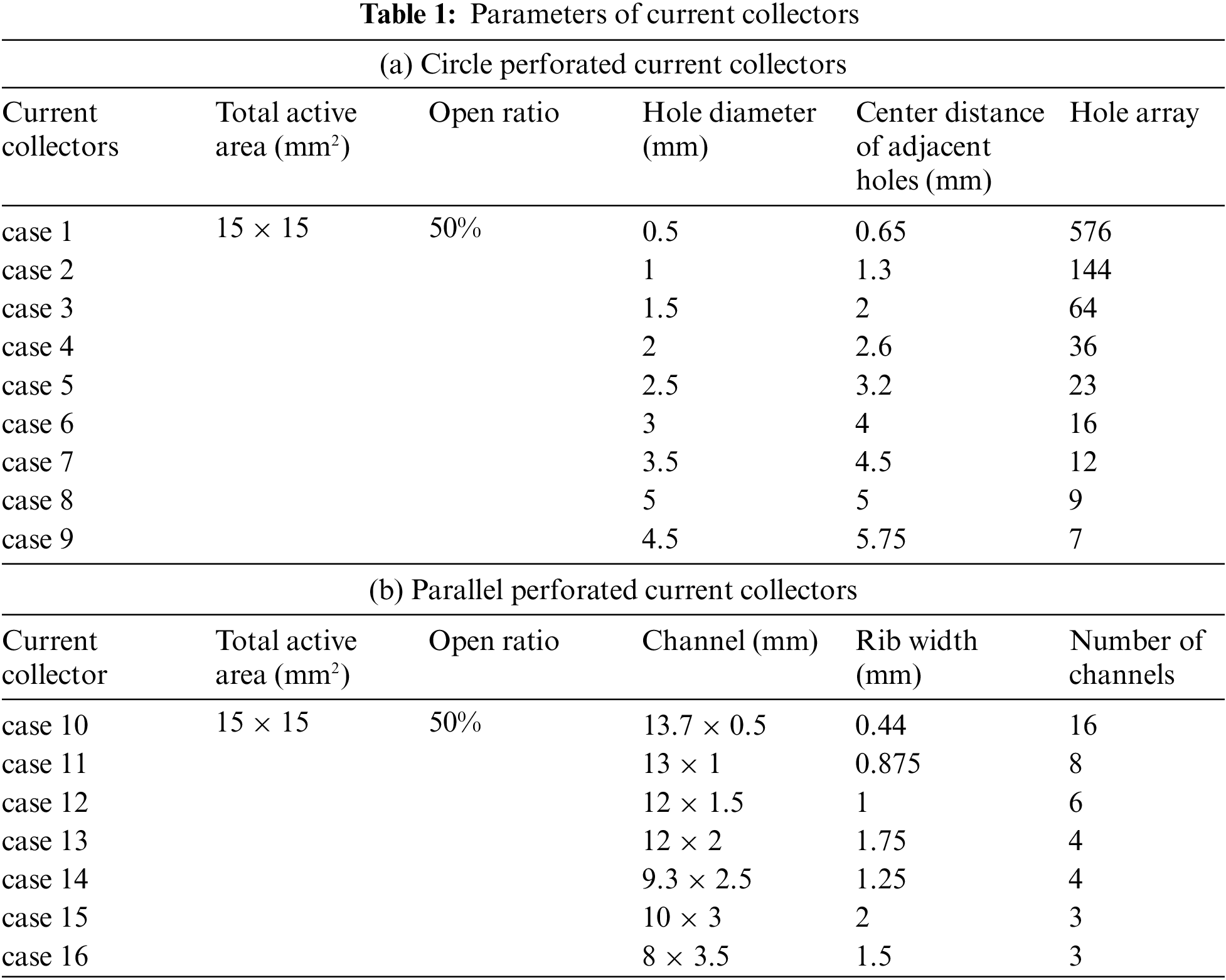
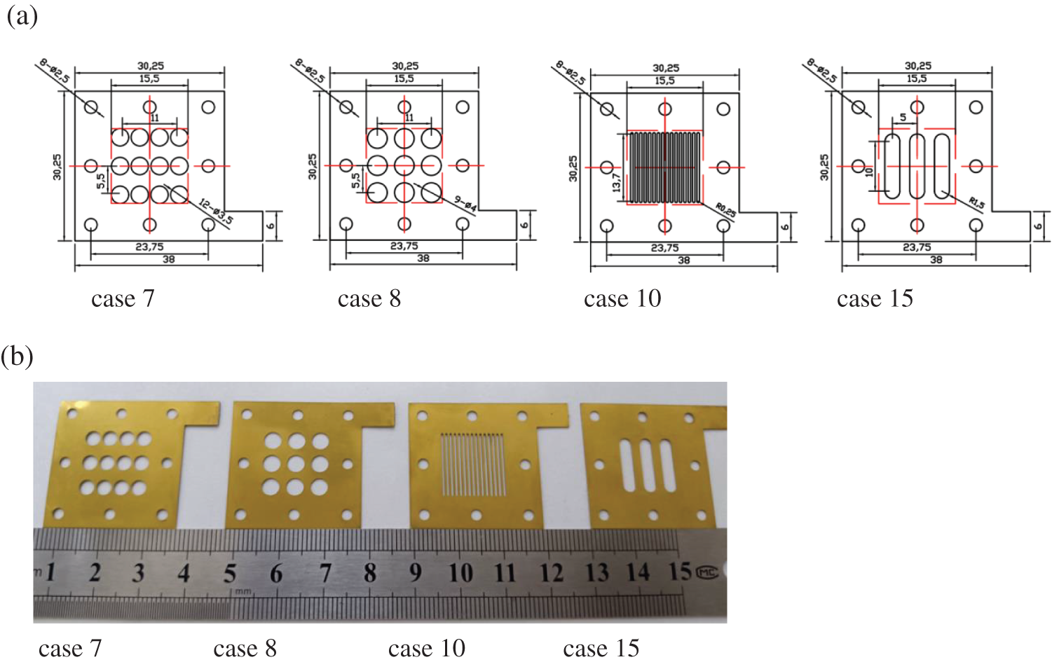
Figure 1: Configuration of perforated and parallel current collectors. (a) Some dimensioned drawings. The active area of the fuel cell is within the red dashed line. (b) Some picture of the current collectors
The experimental setup is shown in Fig. 2. The structure of the DMFC is designed as shown in Fig. 3 to facilitate the self-breathing of the fuel cell. For each test, the following conditions were consistent. For the reaction materials of the cathode and anode, 1 M aqueous methanol solution and oxygen were passively supplied from the methanol chamber and air, respectively. The performance of the cell was analyzed by polarization curves. In general, a thermal management system is necessary for the fuel cell system to keep a suitable working temperature. In this paper, the single cell experiment was carried out in a constant temperature. The temperature was maintained at 50°C, and the packing pressure of the fuel cell was 0.5 MPa. The heat generated by chemical reaction is not enough to change the temperature of the fuel cell because the active area is rather small. Therefore, the generated heat is ignored in this work.
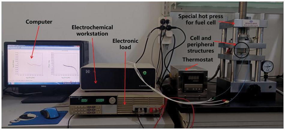
Figure 2: Experimental setup
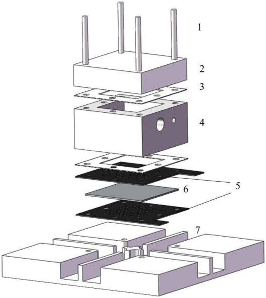
Figure 3: The structure of the DMFC. (1 Pin, 2 Anode End Plate, 3 Gasket, 4 Methanol Chamber, 5 Anode and Cathode Current Collector, 6 MEA, 7 Cathode End Plate)
3.1 Geometry Effects of the Anode Side
In this test, the cathode current collector is made of stainless steel mesh coated with titanium nitride. The polarization curves of the DMFC are shown in Fig. 4a to describe the performance of perforated current collectors with different hole diameters. When the hole diameter is taken as 0.5 mm, the corresponding peak power is 22.5 mW. With an increase in the hole diameter, the peak power first reaches the maximum value of 25.5 mW. Then, the power decreases continuously to 21.6 mW when the hole diameter of the current collector increases to 4.5 mm. The cell achieved its best performance of 25.5 mW with the anode current collector at a hole diameter of 2.5 mm. The peak power was increased by 18% compared with the lowest peak power. The change in the current collector structure has slight effects on the ohmic resistance because the open ratio and pressure of the current collector are basically the same in each experiment. The peak power increases with increasing hole diameter, which shows that the decrease in mass transfer resistance effectively promotes the electrochemical reaction, accelerates the emission of CO2 bubbles and promotes fuel transfer. This is because too small a hole diameter would prevent the discharge of CO2 bubbles. When the hole diameter is larger than 2.5 mm, the peak power decreases gradually, which shows that the mass transfer resistance increases gradually. This is because the width of the land is larger than 1 mm in the case of hole diameters larger than 2.5 mm. Because the width of the land is too large, the bubbles in the diffusion layer cannot be discharged from the flow field in time and effectively through the hole, and the mass transfer resistance increases with increasing width of the land. But the change in ohmic resistance is very slight relative to the change in mass transfer resistance, which has little effect on the electrochemical reaction of the fuel cell.
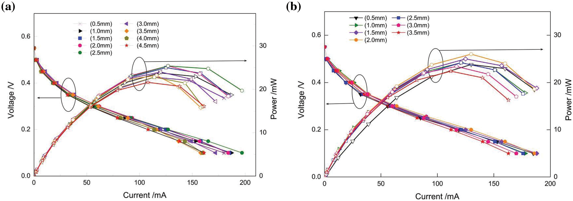
Figure 4: Performance of the DMFC with different Anode Current Collectors. (a) Perforated flow field, (b) Parallel flow field
Fig. 4b shows the performance of the DMFC with an anode parallel current collector at different width channels. Similar to the case of the perforated current collectors, the output power of the DMFC increased first and then decreased as the channel width increased. The maximum power was 26 mW when the channel width was 2 mm. When the channel width was less than 2 mm, the performance differences were not very significant. However, when the width exceeded 2 mm, an obvious performance decline trend could be found. Similar to the perforated collector plate, the structure of the current collector has little effect on ohmic resistance because of the same open ratio and pressure. When the channel width of the parallel current collector is small, the performance of the fuel cell is affected because the large bubbles cannot be eliminated. However, the longer channel has little effect on the blocking of the large bubbles because the parallel flow field is different from the small hole area of the perforated flow field. When the channel width is greater than 2 mm, the increase in the channel width leads to obvious performance degradation, which may be due to the shorter total hole perimeter [25].
3.2 Geometry Effects of the Cathode Side
A stainless steel mesh coated with TiN was used as the anode current collector in this test. The polarization curves of DMFC are shown in Fig. 5a to describe the performance of perforated current collectors as a function of hole diameters. As shown in Fig. 4a, the peak power gradually increases to the maximum value of 13.2 mW when the hole diameter of the cathode current collector increases from 0.5 to 2.5 mm. The power decreases gradually as the hole diameter increases from 2.5 to 4.5 mm. This was similar to the conclusions obtained from the previous anode experiment. Small water droplets undergo a process of condensing into large droplets, and too small a hole blocks the discharge of large droplets on the cathode side. On the other hand, the larger holes result in a larger land width, which leads to the H2O droplets in the diffusion layer not being discharged from the flow field. At the same time, these larger holes lead to the larger mass transfer resistance of O2.
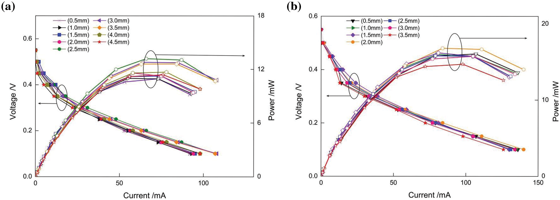
Figure 5: Performance of the DMFC with different Cathode Current Collectors. (a) Perforated flow field, (b) parallel flow field
Fig. 5b illustrates the performance of the DMFC with a cathode parallel current collector at different width channels. Similar to the case of the anode experiment, the output power of the DMFC increased first and then decreased as the channel width increased, and the optimal channel width was 2 mm. This shows that the CO2 bubbles and H2O droplets that formed in the diffusion layer need an appropriate size to promote their maximum discharge during growth and discharge and that an improper hole diameter or channel width will inhibit this process.
The cell performance of this section is lower than that of Section 3.1. The reason may be that stainless steel mesh was used as the cathode current collector in Section 3.1 and as the anode current collector in this section. Small holes in the tight mesh would increase the mass transfer resistance of carbon dioxide bubbles on the anode side. When the stainless steel mesh is used as the cathode current collector in Section 3.1, the cathode is open to the air and the oxygen supply is relatively smooth. However, when the stainless steel mesh is used as the anode current collector in Section 3.2, the generated CO2 bubbles will adhere to the mesh because of the surface tension, and thus the mass transfer resistance will increase.
3.3 Geometry Effects of Both Anode and Cathode Sides
Fig. 6a shows the polarization curve of the DMFC with identical perforated anode and cathode current collectors. As the diameter of the current collector increased, the maximum power of the cell increased and then decreased. The peak power of 19.6 and 18.8 mW could be obtained when the diameter was 1.5 and 2 mm, respectively. The optimal diameter in this experiment is slightly smaller than that in the above sections (2.5 mm). The reason may be the mesh effect on the other side. Fig. 6b shows the performance of the DMFC with identical parallel anode and cathode current collectors. The performance of the cell still first increased and then decreased as the channel width increased. In this case, the channel width of 2 mm reached a maximum power of 25.8 mW. This is similar to the maximum power values described in Sections 3.1 and 3.2.
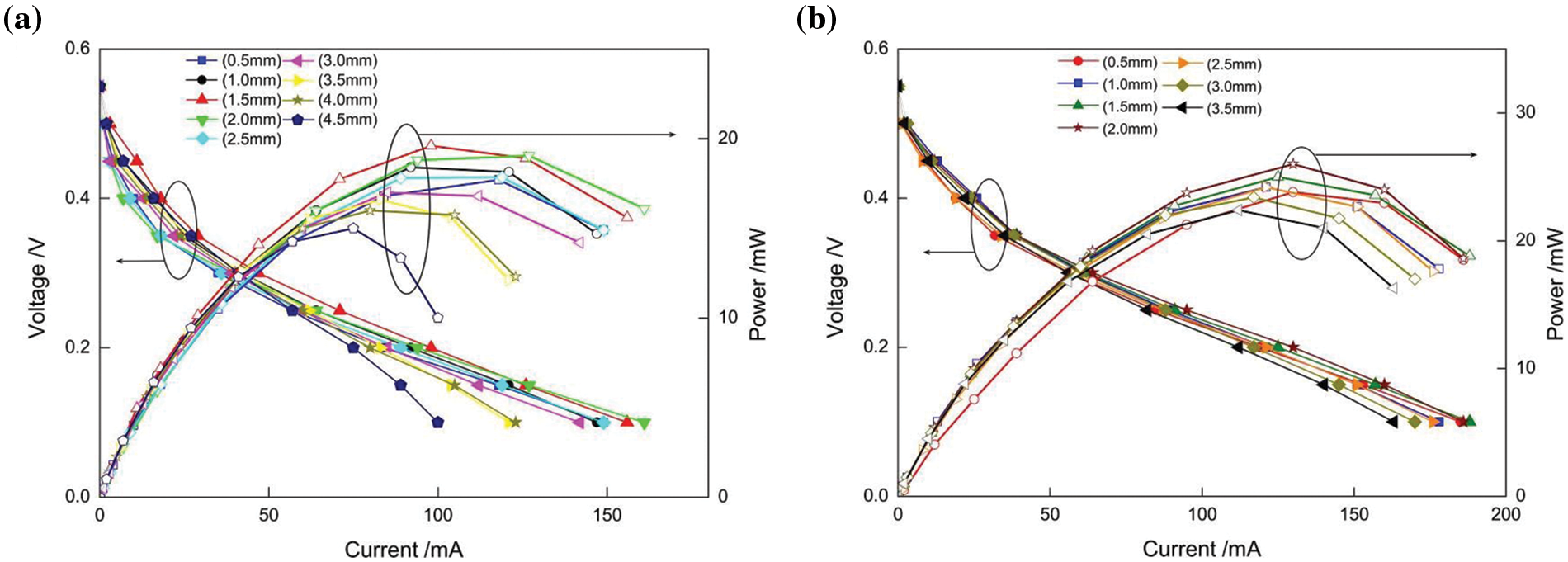
Figure 6: Performance of the DMFC with a pair of Current Collectors. (a) Perforated flow field, (b) parallel flow field
Fig. 7 shows the peak power of the cell with different current collector combinations under different feature sizes, as discussed in the above sections. The maximum peak power can be achieved when the feature diameter of the anode current collector is 2.5 mm for the perforated flow field. The reason may be that the stainless steel mesh is more beneficial for the uniform transmission of oxygen than the perforated flow field at the cathode side. For a parallel flow field, the stainless steel mesh at the anode side may block the transmission of the CO2 bubble, which leads to a lower peak power, as shown in Fig. 7. The peak power is 26 mW and the active area of the cell is 2.25 cm2, thus the peak power density of 11.6 mW·cm−2 can be obtained. Compared to literature [3] and [5], which have similar working conditions, the peak power density of this work is 8.4% higher than [5] and 20% lower than [3]. This shows that the optimal open ratio may depend on the structures of current collectors.
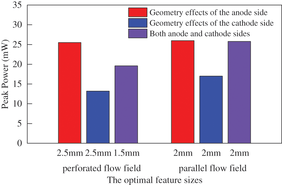
Figure 7: Peak power of the cell with different current collector combinations
3.4 The Effects of Rib and Channel Position
To investigate the position effect of the parallel anode and cathode current collectors, three patterns were considered: aligned, alternating and vertical (shown in Fig. 8). The former two cases were also simulated by Lu et al. [26] and Liu et al. [27], and they found that the influence differed with several factors. The open ratio of the parallel anode and cathode current collectors was also 50%. The channel widths were 0.5 and 1 mm. From the performance of the DMFC in Fig. 9, it can be seen that the peak power of the DMFC with the 0.5 mm channel was 18.8, 17.8, and 16.8 mW, while that with the 1 mm channel was 17.4, 18.4, and 19.4 mW. It is interesting to note that the performance trends of the 0.5 and 1 mm DMFCs were completely opposite. In the case of the 0.5 mm channel, the aligned fuel cell showed the best performance. However, for the 1 mm channel case, the vertical fuel cell performance was the best. It is well known that mass transport resistance impacts cell performance most greatly. When the channel was too narrow (0.5 mm), the mass transfer resistance of methanol and oxygen became very high. The extended transmission path would further increase the mass transfer resistance if the channel was not aligned. When the channel width was large (1 mm), the alternating and vertical cell produced a more uniform stress distribution and may result in lower internal resistance [27]. As shown in Fig. 10, when the channel width is 0.5 mm, the rib is relatively narrow, and consequently the relative position has little effect on the stress distribution. For the case of 1 mm, the relatively wider rib may result in uneven stress distribution for the aligned pattern.
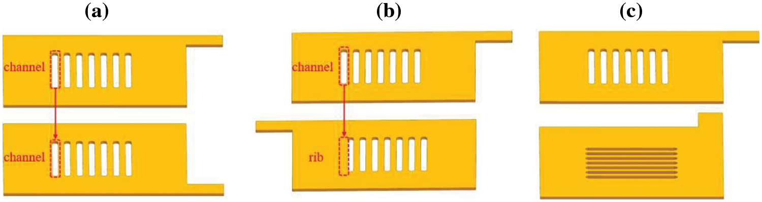
Figure 8: Three patterns of the relative position of the parallel Anode and Cathode Current Collectors. (a) Aligned, (b) alternating, (c) vertical
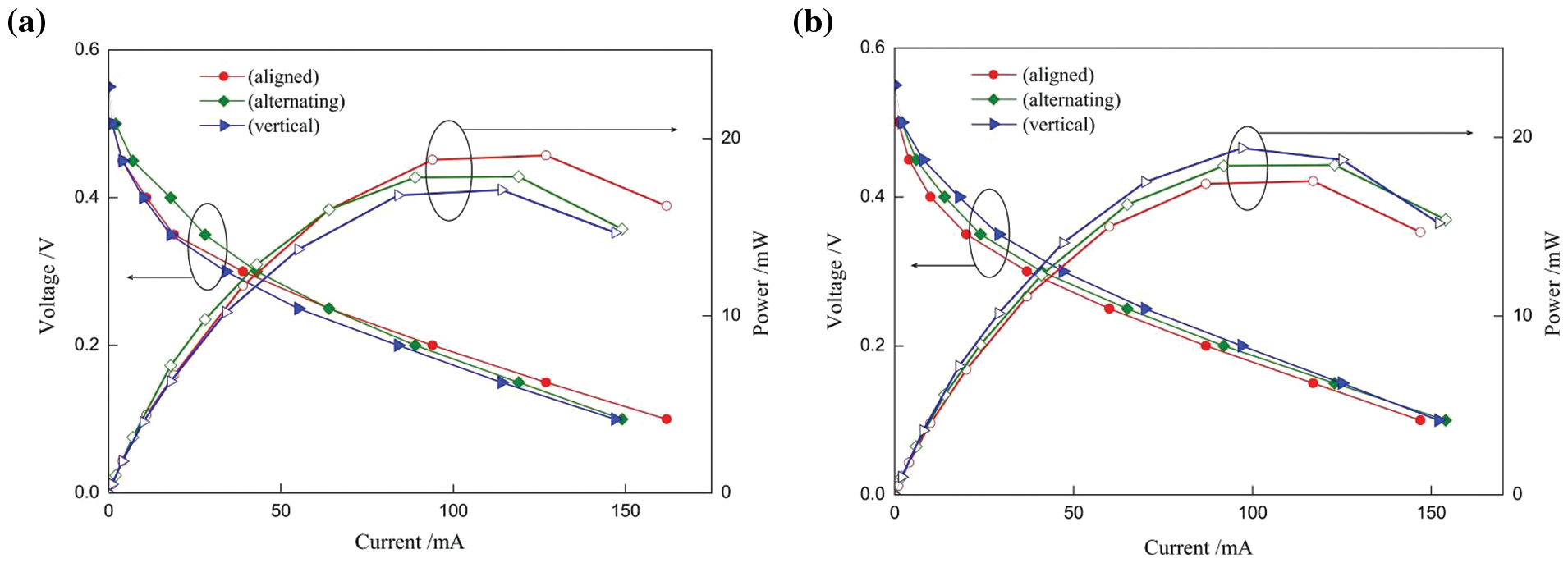
Figure 9: The performance of DMFCs with different positions of a pair of parallel Current Collectors. (a) With the channel width of 0.5 mm, (b) with the channel width of 1 mm
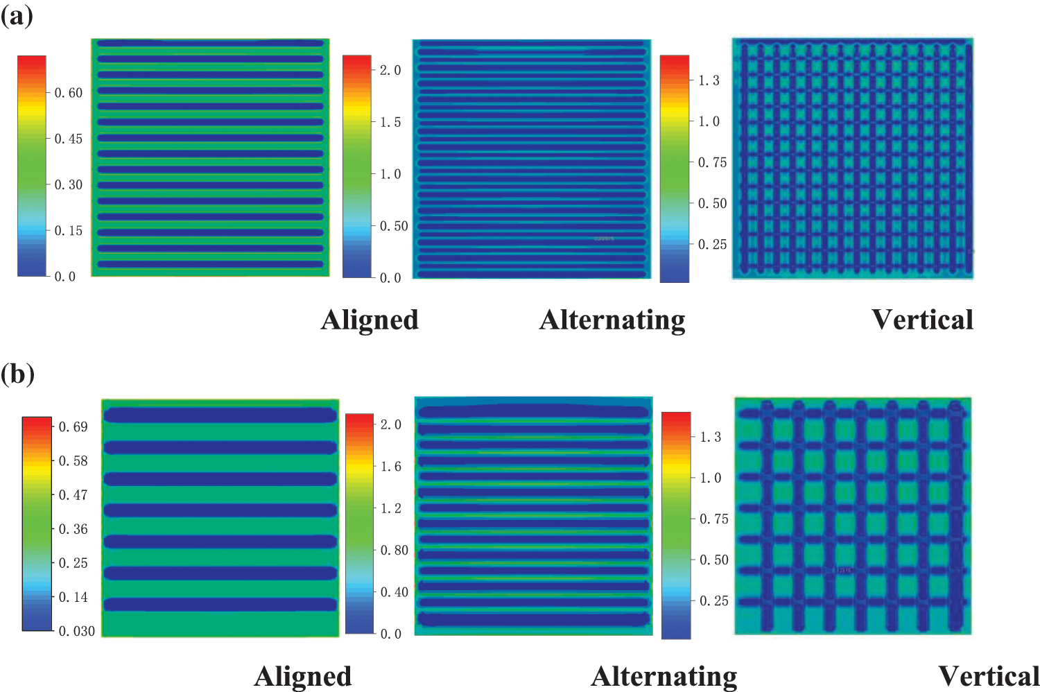
Figure 10: Stress distribution (MPa). (a) With the channel width of 0.5 mm, (b) with the channel width of 1 mm
When the cathode or anode current collector of a DMFC adopts different geometric structures, it is usually difficult to maintain a consistent open ratio. The structural design of parallel and perforated current collectors was carried out in this study to maintain an open ratio of 50%, which was considered the optimal open ratio in many previous studies. The optimal diameter of perforated holes was 2.5 mm for anode or cathode current collectors used separately and 1.5 or 2 mm for a pair of current collectors. The optimal width of the channels was 2 mm for parallel current collectors. This indicates that the optimal feature sizes lie between 2 and 2.5 mm for the flow field in the current collectors with an equal open ratio of 50%. The effects of rib and channel position were also investigated, and the results show that the optimum pattern depends on the channel width of the flow field.
Acknowledgement: None.
Funding Statement: This research is supported by the National Natural Science Foundation of China (No. 51405342), Natural Science Foundation of Tianjin (No. 20JCYBJC00050), and Jiangsu Key Laboratory of Precision and Micro-Manufacturing Technology.
Author Contributions: The authors confirm contribution to the paper as follows: study conception and design: Yingli Zhu; data collection: Jiachi Xie, Jun Zhang; analysis and interpretation of results: Mingwei Zhu; draft manuscript preparation: Yingli Zhu, Miaomiao Li. All authors reviewed the results and approved the final version of the manuscript.
Availability of Data and Materials: Data supporting this study are included within the article.
Conflicts of Interest: The authors declare that they have no conflicts of interest to report regarding the present study.
References
1. Deng, H., Zhou, J., Zhang, Y. (2021). Design and simulation of air-breathing micro direct methanol fuel cells with different anode flow fields. Micromachines, 12(3), 253. [Google Scholar] [PubMed]
2. Yang, H., Zhao, T. (2004). Effect of anode flow field design on the performance of liquid feed direct methanol fuel cells. Electrochimica Acta, 50(16), 3243–3252. [Google Scholar]
3. Wang, L., Yin, L., Yang, W., Cheng, Y., Wen, F. et al. (2021). Evaluation of structural aspects and operation environments on the performance of passive micro direct methanol fuel cell. International Journal of Hydrogen Energy, 46(2), 2594–2605. [Google Scholar]
4. Braz, B. A., Moreira, C. S., Oliveira, V. B., Pinto, A. M. F. R. (2019). Effect of the current collector design on the performance of a passive direct methanol fuel cell. Electrochimica Acta, 300, 306–315. [Google Scholar]
5. Tang, Y., Yuan, W., Pan, M., Tang, B., Li, Z. et al. (2010). Effects of structural aspects on the performance of a passive air-breathing direct methanol fuel cell. Journal of Power Sources, 195(17), 5628–5636. [Google Scholar]
6. Zhang, B., Zhang, Y., He, H., Li, J., Yuan, Z. et al. (2010). Development and performance analysis of a metallic micro-direct methanol fuel cell for high-performance applications. Journal of Power Sources, 195(21), 7338–7348. [Google Scholar]
7. Xu, X., Yang, W., Zhuang, X., Xu, B. (2019). Experimental and numerical investigation on effects of cathode flow field configurations in an air-breathing high-temperature PEMFC. International Journal of Hydrogen Energy, 44(45), 25010–25020. [Google Scholar]
8. Calabriso, A., Cedola, L., Zotto, L. D., Rispoli, F., Santori, S. G. (2015). Performance investigation of passive direct methanol fuel cell in different structural configurations. Journal of Cleaner Production, 88, 23–28. [Google Scholar]
9. Kianimanesh, A., Yu, B., Yang, Q., Freiheit, T., Xue, D. et al. (2012). Investigation of bipolar plate geometry on direct methanol fuel cell performance. International Journal of Hydrogen Energy, 37(23), 18403–18411. [Google Scholar]
10. Park, Y. C., Chippar, P. C., Kim, S. K., Lim, S., Jung, D. H. et al. (2012). Effects of serpentine flow-field designs with different channel and rib widths on the performance of a direct methanol fuel cell. Journal of Power Sources, 205, 32–47. [Google Scholar]
11. Gholami, O., Imen, S. J., Shakeri, M. (2013). Effect of non-uniform parallel channel on performance of passive direct methanol fuel cell. International Journal of Hydrogen Energy, 38(8), 3395–3400. [Google Scholar]
12. Gholami, O., Imen, S. J., Shakeri, M. (2015). Effect of anode and cathode flow field geometry on passive direct methanol fuel cell performance. Electrochimica Acta, 158, 410–417. [Google Scholar]
13. Osman, S., Ahmed, M. (2022). Enhancing the performance of direct methanol fuel cells via a new anode design for carbon dioxide bubbles removal. Energy Conversion and Management, 251, 114958. [Google Scholar]
14. Hu, X., Yang, Q., Xiao, G., Chen, X., Qiu, X. (2019). Power generation enhancement in direct methanol fuel cells using non-uniform cross-sectional serpentine channels. Energy Conversion and Management, 188, 438–446. [Google Scholar]
15. Wang, X., Qin, Y., Wu, S., Xiang, S., Zhang, J. et al. (2020). Numerical and experimental investigation of baffle plate arrangement on proton exchange membrane fuel cell performance. Journal of Power Sources, 457, 228034. [Google Scholar]
16. Jałowiecka, M., Bojarska, Z., Małolepszy, A., Makowski, L. (2023). Mass transport enhancement in direct formic acid fuel cell with a novel channel design. Chemical Engineering Journal, 451(1), 138474. [Google Scholar]
17. Bagherighajari, F., Ramiar, A., Abdollahzadehsangroudi, M., Páscoa, J. C., Oliveira, P. J. (2022). Numerical simulation of the polymer electrolyte membrane fuel cells with intermediate blocked interdigitated flow fields. International Journal of Energy Research, 46(11), 15309–15331. [Google Scholar]
18. Ouellette, D., Ozden, A., Ercelik, M., Colpan, C. O., Ganjehsarabi, H. et al. (2018). Assessment of different bio-inspired flow fields for direct methanol fuel cells through 3D modelling and experimental studies. International Journal of Hydrogen Energy, 43(2), 1152–1170. [Google Scholar]
19. He, L., Hou, M., Gao, Y., Fang, D., Wang, P. et al. (2020). A novel three-dimensional flow field design and experimental research for proton exchange membrane fuel cells. Energy Conversion and Management, 205, 112335. [Google Scholar]
20. Ozden, A., Ercelik, M., Ouellette, D., Colpan, C. O., Ganjehsarabi, H. et al. (2017). Designing, modelling and performance investigation of bio-inspired flow field based DMFCs. International Journal of Hydrogen Energy, 42(33), 21546–21558. [Google Scholar]
21. Ramasamy, J., Karthikeyan, P., Kumaresan, T., Chandran, M., Chen, R. (2022). Study of novel flow channels influence on the performance of direct methanol fuel cell. International Journal of Hydrogen Energy, 47(1), 595–609. [Google Scholar]
22. Li, J., Wang, H., Lin, P., Wang, G., Sun, J. et al. (2022). Research about two-step channel with lateral narrowing structures in the flow mass transfer of proton exchange membrane fuel cell. Fuel Cell, 22(3), 58–70. [Google Scholar]
23. Sauermoser, M., Pollet, B. G., Kizilova, N., Kjelstrup, S. (2021). Scaling factors for channel width variations in tree-like flow field patterns for polymer electrolyte membrane fuel cells—an experimental study. International Journal of Hydrogen Energy, 46(37), 19554–19568. [Google Scholar]
24. He, L., Hou, M., Gao, Y., Sun, X., Song, W. et al. (2020). Experimental study of the S-shaped flow fields in proton exchange membrane fuel cells. Energy Conversion and Management, 223, 113292. [Google Scholar]
25. Chang, J., Kuan, Y., Lee, S. M., Lee, S. R. (2008). Characterization of a liquid feed direct methanol fuel cell with Sierpinski carpets fractal current collectors. Journal of Power Sources, 184(1), 180–190. [Google Scholar]
26. Lu, Z., Kim, C., Karlsson, A. M., Cross III, J. C., Santare, M. H. (2011). Effect of gas diffusion layer modulus and land-groove geometry on membrane stresses in proton exchange membrane fuel cells. Journal of Power Sources, 196(10), 4646–4654. [Google Scholar]
27. Liu, Z., Zhang, H., Wang, C., Mao, Z. (2010). Numerical simulation for rib and channel position effect on PEMFC performances. International Journal of Hydrogen Energy, 35(7), 2802–2806. [Google Scholar]
Cite This Article
 Copyright © 2024 The Author(s). Published by Tech Science Press.
This work is licensed under a Creative Commons Attribution 4.0 International License , which permits unrestricted use, distribution, and reproduction in any medium, provided the original work is properly cited.
 Downloads
 Citation Tools