
 Submit a Paper
 Propose a Special lssue
 Open Access
ARTICLE

Analysis of DC-Side Harmonic Characteristics and Optimization of Filter Design for Hybrid DC Transmission Systems
1 School of Electrical and Electronic Engineering, Chongqing University of Technology, Chongqing, 400054, China
2 Shi Bei Power Supply Branch, State Grid Chongqing Electric Power Company, Chongqing, 401120, China
3 Carbon Neutrality Research Institute, Chongqing Communication Design Institute Co., Ltd., Chongqing, 400041, China
* Corresponding Author: Wenyan Li. Email:
(This article belongs to the Special Issue: Operation and Control of Grid-connected New Energy and Emerging Loads)
Energy Engineering 2025, 122(10), 4313-4330. https://doi.org/10.32604/ee.2025.070187
Received 10 July 2025; Accepted 28 August 2025; Issue published 30 September 2025
 View Full Text
 Download PDF
Abstract
To accelerate the large-scale integration of renewable energy and support the strategic goals of “carbon peaking and carbon neutrality,” High Voltage Direct Current (HVDC) transmission technology has made significant breakthroughs. Among the various approaches, a hybrid DC transmission system that combines a line-commutated converter (LCC) and a voltage source converter (VSC) retains the inherent fault self-clearing capability of the LCC topology while mitigating the risk of commutation failure when connected to a weak grid. In this paper, based on the harmonic generation mechanisms of hybrid DC transmission systems, an improved 3-pulse harmonic source model of the LCC and a dynamic phase-sequence harmonic analysis model of the VSC are developed. The integrated harmonic model demonstrates strong adaptability in accurately calculating DC-side harmonics under the influence of power imbalances and background harmonics. Based on this model, the fundamental characteristics of DC-side harmonics in hybrid DC transmission systems are analyzed. To mitigate harmonic effects, this paper proposes an LCLC-trap2 high-order filter structure with parallel RC damping circuits and a co-optimized design of filter parameters. Finally, a ±500 kV hybrid DC transmission system is modeled using the MATLAB/Simulink platform, and the harmonic filtering performances of the conventional LC filter, the Butterworth filter, and the proposed filter are simulated and compared. The results verify that the proposed filter offers superior performance in suppressing low-order harmonics under non-ideal operating conditions.Keywords
Accelerating the utilization of renewable energy is essential for achieving clean energy goals and promoting the development of the “dual carbon” strategy. However, since renewable energy sources are often located far from load centers, large-capacity and long-distance energy transmission is required. As a result, high-voltage direct current (HVDC) transmission technology has been gradually developing and expanding [1]. Line-commutated converter HVDC (LCC-HVDC) systems have become the dominant and mature engineering solution for HVDC transmission. However, LCC-HVDC suffers from commutation failures, high reactive power consumption, and limited ability to handle AC-side faults [2]. On the other hand, voltage source converter HVDC (VSC-HVDC) systems utilize fully controlled devices and pulse width modulation technology, which enable decoupled control of active and reactive power and eliminate the risk of commutation failures [3]. Nevertheless, the transmission capacity of VSC-HVDC is generally lower than that of LCC-HVDC, and DC-side faults in VSC systems evolve rapidly, with high fault current magnitudes and no natural current zero-crossing, making fault isolation difficult. A hybrid DC transmission system, combining LCC and VSC technologies, retains the fault-clearing capability of LCC while avoiding commutation failures associated with weak AC grids, thereby improving the stability of the receiving-end system and the capability of DC line power delivery [4].
However, the widespread deployment of nonlinear power electronic devices introduces substantial harmonic distortion. Harmonics in LCC systems include both characteristic and non-characteristic harmonics. Characteristic harmonics arise under ideal conditions and are determined by the converter pulse number—for instance, a 12-pulse rectifier typically generates harmonics at integer multiples of the 12th order. Non-characteristic harmonics, however, are caused by non-ideal factors such as unbalanced three-phase voltages, coupled leakage reactance in Yy and Yd configurations, transformer ratio mismatches, and converter valve firing inconsistencies [5,6]. VSC systems primarily generate high-frequency harmonics during normal operation, but non-ideal conditions such as phase asymmetry can also introduce significant low-order non-characteristic harmonics. Consequently, in LCC-VSC hybrid DC transmission systems, the DC-side low-frequency harmonic content increases significantly, adversely affecting both power transmission efficiency and electromagnetic compatibility, and, in extreme cases, hindering the grid integration of renewable energy. Therefore, it is critical to analyze the harmonic characteristics of the DC side and design appropriate filtering solutions [7,8]. DC-side filters mainly include tuned filters, active filters, and low-pass filters. References [9–11] propose hybrid filter structures composed of tuned filters, which reduce the need for reactive power compensation equipment but have limited effectiveness in suppressing low-order harmonics. Reference [12] proposes a DC hybrid active power filter combining an active power filter and a CL filter to suppress low- and high-frequency harmonics, and achieves single-loop energy control via feedback linearization, resulting in effective DC-side harmonic suppression in a 500 W single-stage single-phase inverter. References [13,14] explore high-power active power filters that not only meet harmonic filtering requirements but also provide dynamic reactive power compensation. However, active filters may introduce negative impedances, which can lead to system resonance and potential stability issues, along with high implementation costs.
In summary, tuned filters exhibit low impedance at specific harmonic orders but are less effective at suppressing low-order harmonics. Active filters are capable of dynamically suppressing harmonics with varying amplitudes and frequencies, but their application is limited by capacity constraints and high implementation costs. Low-pass filters effectively attenuate harmonics above the cutoff frequency and are widely used for DC-side filtering under various converter operating conditions. References [15,16] propose inductor-based filtering methods to eliminate non-characteristic harmonics in DC transmission systems. Reference [17] analyzes the harmonic characteristics of the DC side in LCC–MMC hybrid DC transmission systems and proposes using Butterworth filters to suppress low-order non-characteristic harmonics. However, the filter parameters were not optimized, resulting in insufficient suppression of the second-order harmonics on the DC side.
Although extensive research has been conducted on the harmonic characteristics and filtering techniques for the AC side of hybrid DC transmission systems [18], relatively few studies have focused on the analysis and suppression of non-characteristic harmonics on the DC side. This paper focuses on analyzing the DC-side harmonic characteristics and optimizing the filter parameters of a hybrid DC transmission system, in which an LCC is used on the rectifier side and a VSC on the inverter side. To address the limitation that conventional three-pulse harmonic source models cannot simulate non-ideal operating conditions, an improved LCC-based three-pulse harmonic source model is proposed. This model accounts for the effects of voltage source asymmetry and background harmonics. For the harmonic analysis of the inverter-side VSC, a sparse vector method is employed, and the interactions between harmonics on the AC and DC sides are represented using a path tree of forward and backward generation operations. The proposed harmonic analysis model enables accurate analysis of the DC-side harmonic characteristics in the hybrid DC transmission system. To mitigate the effects of low-order harmonics under non-ideal conditions, an LCLC-trap2 filter structure with a parallel RC damping circuit is adopted, and its parameters are optimally designed. Finally, a hybrid DC transmission model is developed on the MATLAB/Simulink platform to compare the filtering performances of the LC filter, the Butterworth filter, and the proposed filter. Simulation results verify that the proposed filter demonstrates superior performance in suppressing low-order harmonics.
2 Harmonic Characterization of Hybrid DC Transmission
2.1 Hybrid DC Transmission System Structure and Control
To address commutation failures in conventional DC transmission inverters at the receiving end, and to enhance transmission reliability and reactive power support, hybrid DC transmission systems that combine LCC and VSC are commonly adopted. The specific structure is shown in Fig. 1. Equipped with a 12-pulse converter on the rectifier side and a two-level converter on the inverter side, the hybrid topology can supply power to weak AC systems or even passive networks, and can also serve as a power source for black-start operations.
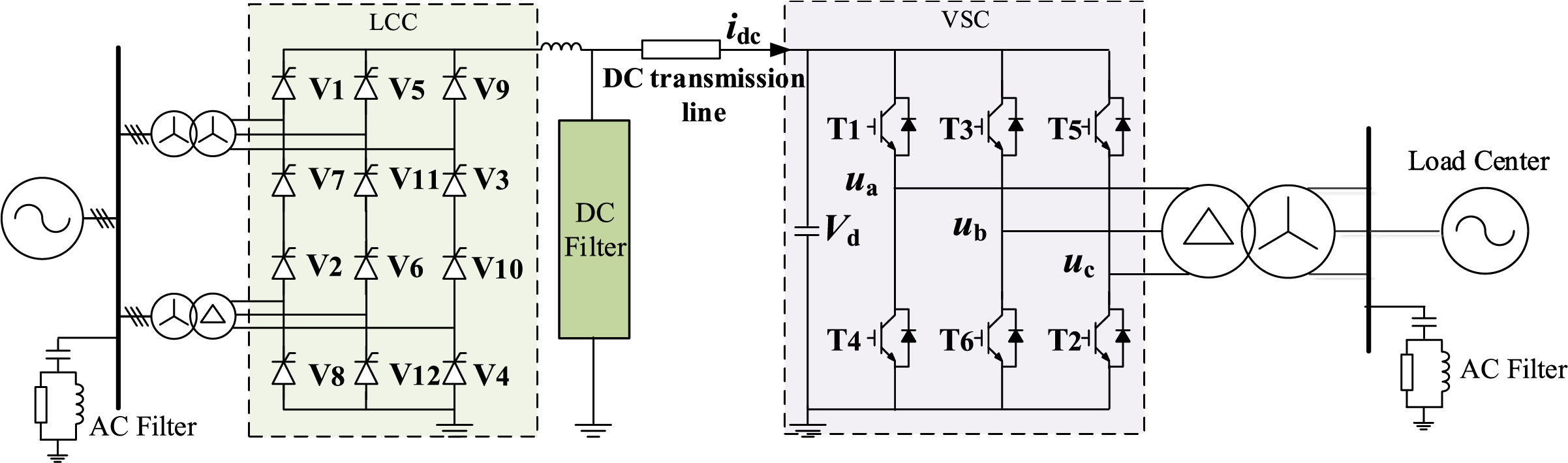
Figure 1: Structural diagram of a single-stage hybrid high-voltage DC transmission system
The control of the VSC can be categorized into system-level control, converter station-level control, and converter -level control. At the system level, control commands are generated based on active and reactive power setpoints. These commands are transmitted to the converter station-level control to ensure continuous and stable operation of the AC/DC hybrid system. System-level control encompasses both active and reactive power control strategies. The active control variables include DC voltage, active power, frequency, and DC current, while the reactive control variables include reactive power and AC voltage. Appropriate control strategies are selected according to specific application requirements [19].
The converter station-level control receives system-level commands and calculates the required pulse width modulation (PWM) ratio and phase angle, which are then delivered to the converter valve-level control as reference signals. This level of control primarily includes DC current control, vector control, and adaptive control. Among these, vector control—owing to its simple structure and rapid dynamic response—is widely used in VSC-based HVDC systems. Therefore, this paper employs vector decoupling control based on the rotating dq reference frame.
The system-level control in a hybrid LCC-VSC configuration differs from that in a conventional two-terminal LCC or VSC system. When the hybrid HVDC transmission system is connected to a weak AC grid or passive network, the VSC operates under AC voltage control to stabilize the AC system voltage. When connected to a strong grid, the allocation of DC voltage control between the sending and receiving ends has minimal impact on the receiving-end AC system. However, considering the fault ride-through capability of the AC/DC system, the sending end should adopt constant-power or constant-current control, while the receiving end should implement constant-voltage control to regulate the DC voltage [20].
2.2 Harmonic Analysis of the DC Side of the Hybrid DC Transmission System
2.2.1 LCC Improvement 3 Pulsating Harmonic Modeling
The harmonic model of the DC side of the LCC typically employs a three-pulse harmonic voltage source model, which includes additional capacitance to simulate the effects of stray capacitance. This model can represent all 3k-order harmonics on the DC side. The harmonic model of a twelve-pulse converter is composed of two six-pulse converters connected in series with a 30° phase shift. Each six-pulse converter can be equivalently modeled as two three-pulse harmonic voltage sources connected in series with an inductor. These two three-pulse sources are phase-shifted by 60° relative to each other. The equivalent three-pulse harmonic model is illustrated in Fig. 2, where L3p represents the equivalent inductance and C1 denotes the added stray capacitance, which is typically selected from 10 to 20 pF in engineering practice [17].
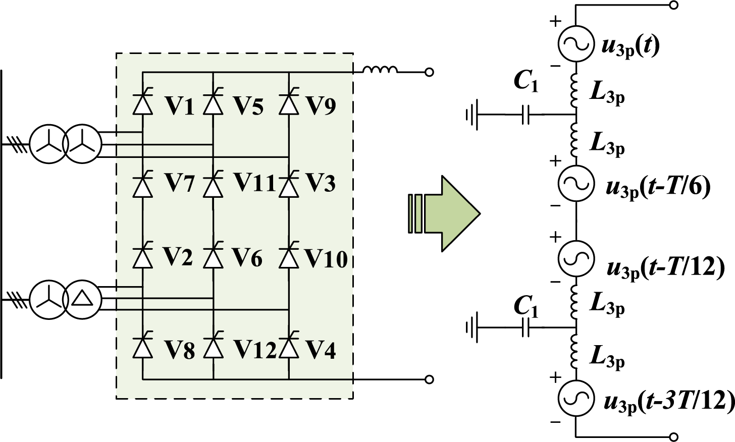
Figure 2: Equivalent three-pulse harmonic source model of a twelve-pulse converter
In the figure, u3p(t) denotes the equivalent voltage source of the first 3-pulse converter, and its Fourier series expansion is shown in Eq. (1). The expressions for the other 3-pulse converters can be derived in a similar manner, with appropriate phase-angle differences, as illustrated in Fig. 2.
where α is the trigger angle, μ is the commutation overlap angle, and the extinction angle δ is given by δ = α + μ, and Udio is the ideal no-load DC voltage. This three-pulse harmonic source model is derived under ideal conditions and captures all characteristic (12k-order) harmonics, but it cannot represent non-characteristic (non-3k-order) harmonics resulting from three-phase imbalances. To model the three-pulse harmonic voltage source under unbalanced conditions, a segmented approach is adopted to separately analyze the commutating and non-commutating phases. The three-pulse harmonic voltage source is divided into six conduction intervals per cycle, corresponding to the conduction sequence of the three valves.
When considering AC grid unbalance, the commutation angles during phase change may differ, αk and μk are the trigger angle and overlap angle of valve k, respectively (k = 1, 5, 9). The three pulsating voltages are Fourier decomposed separately over different segmentation intervals, and then the voltages of the same frequency are summed to obtain the respective harmonic voltages of the three pulsating groups (valves V1, V5, and V7) as shown in Eq. (3).
where a0 is the DC component of the harmonic voltage, and Ua3ph and φa3ph are the amplitude and phase angle of the h-th harmonic voltage, respectively. an and bn are the real and imaginary parts of the n-th harmonic voltage, and they are calculated as follows:
where ua(n), ub(n), and uc(n) denote the n-th AC harmonic voltages of the three phases, and La, Lb, and Lc are the phase inductances of the three phases, respectively.
2.2.2 VSC Harmonic Analysis Model
The harmonic analysis model of the VSC, based on dynamic phasors and sequence components, is formulated using the state-space method as follows:
where X is defined as follows:
X consists of 3n dynamic phasor quantities corresponding to the sequence components of the AC-side current (i.e., each current harmonic sequence component), and the n voltage harmonic components on the DC side. V is the input variable, consisting of the dynamic phasors of the sequence components of the AC-side source voltage. A is the coefficient matrix of the state transfer equation. If the harmonics are considered under steady-state conditions, then
The coefficient matrix A determines the VSC harmonic generation mechanism, and it consists of two diagonal subarrays and two non-diagonal subarrays.
The two diagonal blocks represent the system parameters of the DC and AC sides, respectively. The off-diagonal submatrices contain the dynamic phasors of the sequence components of the switching function, which characterize the interactions between the AC and DC sides over the switching period. When PWM is implemented using three-phase symmetric modulation, the dynamic phasors of the switching function contain only the positive-sequence component of the fundamental waveform and higher-order harmonic components. As a result, matrix A is sparse. The triangular form of matrix A is given as follows:
where L is the lower triangular matrix obtained through the forward generation operation, U is the upper triangular matrix corresponding to the backward generation operation, and D is the diagonal matrix associated with the specification operation. It can be observed that L11 and L22 are identity matrices, indicating that there is no interaction between the dynamic phasors of the AC-side sequence components. The effect of the AC side on the DC side is represented by L21. The non-zero elements of L21 and U12 indicate the interaction between the DC and AC sides, and the magnitude of these elements determines the strength of the coupling. The path tree of the forward and backward operations can be obtained using the sparse vector method; these interaction relationships can then be employed to visually represent the harmonic generation mechanism of the VSC when combined with the assigned directed factor graph.
2.2.3 Harmonic Analysis of Hybrid DC Transmission Systems
(1) Rectifier-side LCC DC harmonic analysis
This paper mainly analyzes the non-characteristic harmonics generated by the LCC under non-ideal conditions. The three-phase voltage can be expressed as follows, assuming that the AC side contains m-th order background harmonics.
where s = +1, –1, and 0 denote the positive-, negative-, and zero-sequence components, respectively, the rectified voltage is expressed as follows:
where the voltage switching function Bk is given by:
For the zero-sequence component, the rectified voltage equals zero. Therefore, the zero-sequence voltage on the AC side of the 12-pulse converter does not propagate to the DC side nor affect the rectified voltage. In contrast, the rectified voltages corresponding to the positive- and negative-sequence components can be calculated and do contribute to the DC-side voltage.
It is observed that the m-th order positive-sequence harmonic on the AC side of the converter gives rise to the following harmonic components on the DC side as a result of modulation by the 12-pulse converter.
When n = 0, the harmonic amplitude reaches its maximum, and the corresponding angular frequency is given by |ωm – ω|, where ωm represents the angular frequency of the source. When ωm is an integer multiple of the fundamental angular frequency ω, the maximum harmonic order becomes |m – 1|. Similarly, the mth negative-sequence harmonic will generate the following harmonic components on the DC side through modulation by the 12-pulse converter.
The presence of negative-sequence components results in the generation of frequency components at |ωm + ω|. The maximum harmonic order becomes |m + 1| when ωm is an integer multiple of the fundamental frequency.
(2) Inverter-side VSC DC harmonic analysis
Under unbalanced conditions, a fundamental negative-sequence voltage occurs in the system, which induces a corresponding fundamental negative-sequence current on the AC side. Let the positive- and negative-sequence components of the AC-side supply voltage be denoted as Uva+ and Uva−, respectively, and the corresponding current sequence components by Ia+ and Ia−. As described in the previous section, the coefficient matrix A can be decomposed into lower and upper triangular matrices L and U, respectively. Strongly correlated branches are preserved during forward and backward operations. The corresponding directed factor graphs based on the forward and backward path trees are illustrated in Figs. 3 and 4. I(i,j) denotes the AC-side harmonic current sequence component, where i is the harmonic order and j = ±1 or 0 indicates the sequence (positive, negative, or zero). Udck denotes the kth DC-side voltage harmonic. Arrows in the diagram indicate the direction of influence, and the numbers on the branches indicate the interaction weights.
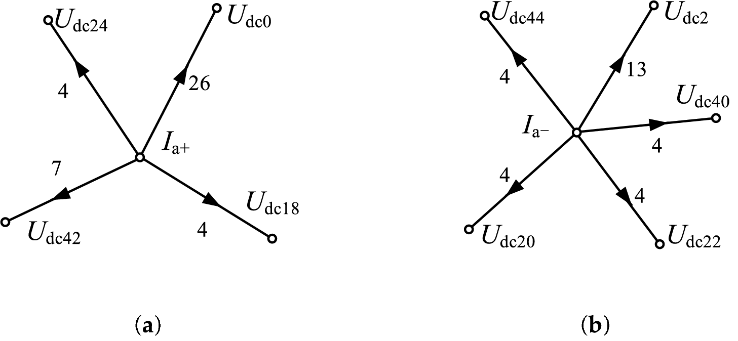
Figure 3: Predecessor operation path tree under voltage asymmetry: (a) Base wave positive sequence current; (b) Base wave negative sequence current
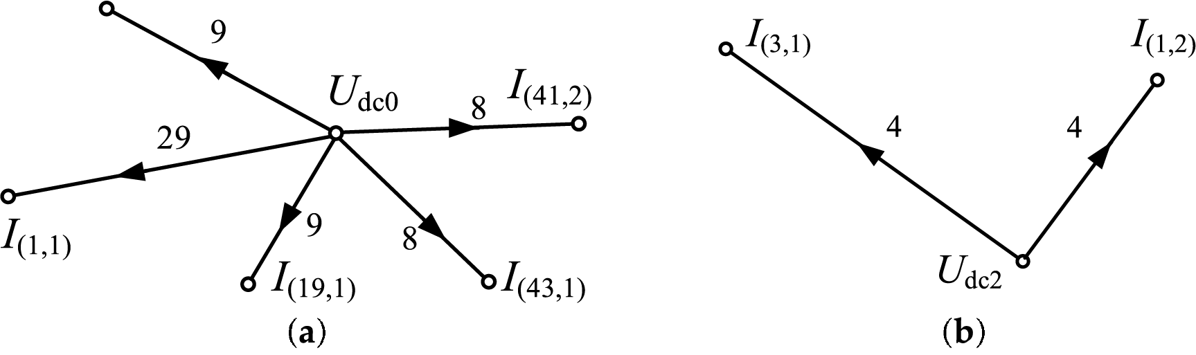
Figure 4: Path tree for back generation operation under voltage asymmetry: (a) DC voltage on the DC side; (b) Second harmonic voltage on the DC side
By ignoring weaker branches, the harmonic interaction between the AC and DC sides can be considered partially decoupled. The forward and backward operations can each be represented by separate subgraphs. The forward operation shows that the fundamental positive- and negative-sequence currents on the AC side affect different harmonic components on the DC side. Conversely, the backward operation reveals how DC-side voltage harmonics influence the positive- and negative-sequence currents on the AC side. It can be observed that under fundamental three-phase voltage unbalance, the DC side contains a significant 2nd harmonic component, along with smaller 20th, 40th, and 44th harmonics. Meanwhile, the AC side exhibits a 3rd-order positive-sequence harmonic.
(3) Harmonic analysis of the DC side of the hybrid DC transmission system
In hybrid DC transmission systems, the DC-side harmonics originate from both characteristic and non-characteristic components generated by the LCC at the rectifier side, and from harmonics generated by the VSC at the inverter side, all of which are transmitted through the DC lines. It is worth noting that the rapid proliferation of nonlinear devices within the AC system significantly elevates background harmonic levels, particularly for the 5th- and 7th-order harmonics. These harmonics are transferred to the DC side through the rectifier or inverter stations, contributing to elevated harmonic content. Additionally, unbalanced operation of the three-phase grid introduces further harmonic distortion into the DC side. In this paper, the combined effects of background harmonics and grid unbalance are considered. The harmonic distribution of the hybrid DC transmission system is illustrated in Fig. 5, assuming a background harmonic injection level of 2% and a 4% AC grid unbalance. It is observed that, due to power supply asymmetry and background harmonics, the DC side exhibits a significant number of low-order harmonics, including the 2nd-, 4th-, 6th-, and 8th-order harmonics, in addition to the 12k-order characteristic harmonics.
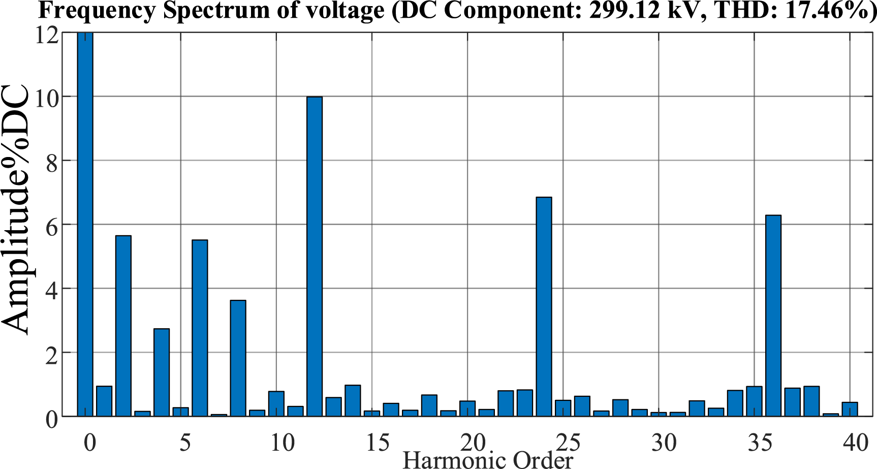
Figure 5: DC side harmonic characteristics of the hybrid DC transmission system
3 DC-Side High-Order Passive Filter Design and Optimization
3.1 Filter Structure Determination
Conventional LC filters are effective in attenuating characteristic harmonics at the DC side. However, they are insufficient for suppressing low-order harmonics induced by frequent three-phase unbalanced conditions and background harmonics, which significantly degrade DC-side power quality. To address this issue, prior studies have proposed third-order Butterworth or Chebyshev filters to enhance low-frequency harmonic attenuation at the DC side. Nevertheless, these filters require large component values, leading to increased physical dimensions and cost. To achieve improved attenuation performance with reduced size and cost, an LC trap circuit is employed as a substitute for large capacitors. Using the third-order Chebyshev filter as an example, a fourth-order LCLC filter circuit is constructed by integrating a DC-side filter inductor. The enhanced higher-order filter topology with the trap circuit integration is shown in Fig. 6.
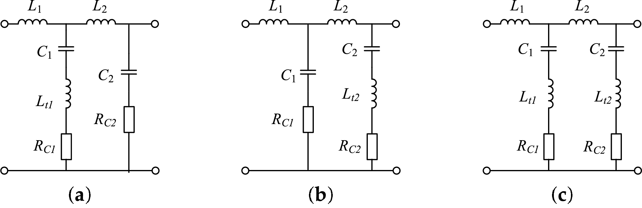
Figure 6: Higher-order filter structure with series damping resistor: (a) LCLC-Trap1-1; (b) LCLC-Trap1-2; (c) LCLC-Trap2
To dampen resonant peaks caused by the reactive components in the higher-order filter circuit, damping circuits are integrated to ensure stable controller operation. The transfer functions for the three damped higher-order filters are:
According to the filtering requirements, the filter parameters used are listed in Table 1. The corresponding Bode plots are shown in Fig. 7, where the solid red, green, and blue lines represent the Bode plots of type 1, type 2 LCLC-Trap filters with series resistors, and LCLC-Trap2 filters, respectively.
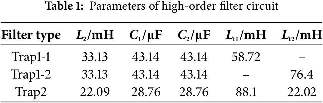
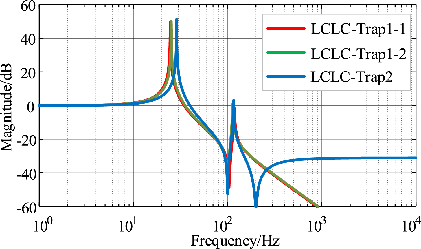
Figure 7: Bode plot of the transfer function of a higher-order filter based on series damping circuits
Comprehensive analysis of Fig. 7 and Table 1 indicates that the LCLC-Trap2 filter maintains comparable low-frequency filtering characteristics while enhancing attenuation performance. This improvement is achieved by replacing capacitors with LC trap circuits, optimizing parameters, and reducing overall size, volume, and cost. However, its high-frequency filtering capability is compromised by damping resistors, suggesting a need for further structural refinement.
3.2 Higher-Order Filter Structure and Parameter Optimization
Series of damping resistors reduce attenuation primarily near the characteristic and tuning frequencies. Therefore, the low- and high-frequency characteristics of the filter remain similar to those of the undamped trap filter. In contrast, the parallel RC damping circuit reduces damping loss while enhancing high-frequency attenuation. Fig. 8 illustrates the Bode plots of the higher-order LCLC-Trap2 filter with different damping configurations. The blue dashed line represents the filter without damping, the red solid line corresponds to the filter with a series damping resistor, and the orange solid line represents the filter with a shunt RC damping circuit.
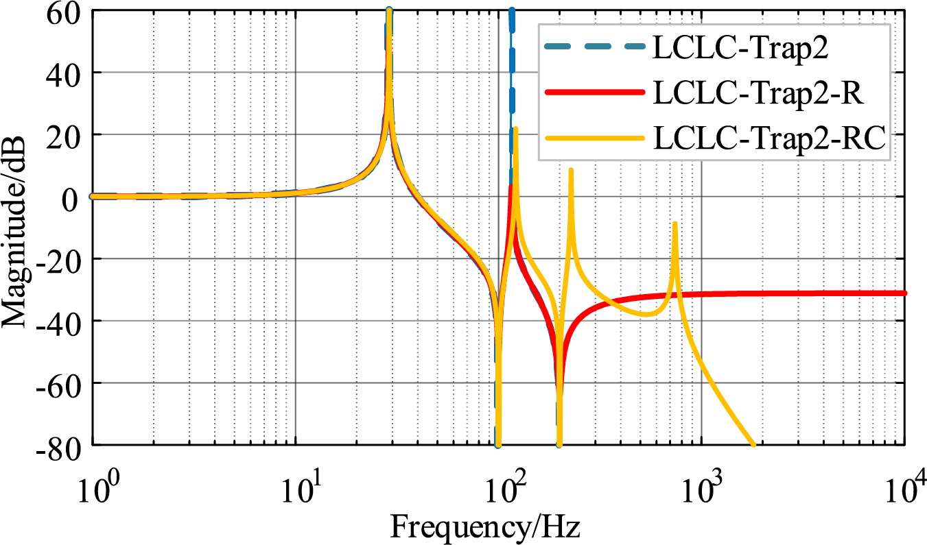
Figure 8: Porter diagram of higher-order trap filter with different damping circuits
It can be observed that the resonance amplitude is significantly higher in the absence of damping circuits. The addition of a series damping resistor primarily reduces the resonance peak, while other frequency characteristics remain similar to the undamped case. In contrast, incorporating shunt damping circuits can significantly enhance high-frequency filtering performance. Therefore, this paper adopts the LCLC-Trap2 filter with shunt RC branches, whose structure is shown in Fig. 9. The total capacitance of each filter branch is maintained by ensuring that the sum of the capacitances in the shunt branches equals the original capacitance values, i.e., Ct1 + Ct = C1 and Ct2 + Cm = C2. The corresponding transfer function is presented in Eq. (20).
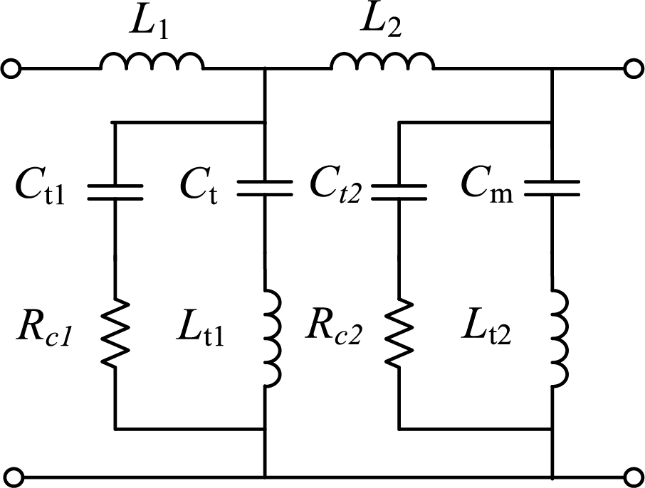
Figure 9: Higher-order trap filter with RC damping circuit in parallel
The transmission performance of the LCLC-Trap filter with a shunt RC damping circuit is closely related to the ratio involving the multiplexed capacitance of the filter, as defined in the following equation. The specific influence of the two parameters on the transfer function is illustrated in Fig. 10. It can be observed from Fig. 10 that variations in the shunt RC damping circuit have little impact on the low-frequency range but significantly affect the frequency band beyond the second trap frequency. The resistance R in the damping circuit primarily influences the resonance amplitude, while its effect on the resonance frequency shift is limited. In contrast, the dominant factor affecting the resonant frequency shift is the change in capacitance C.
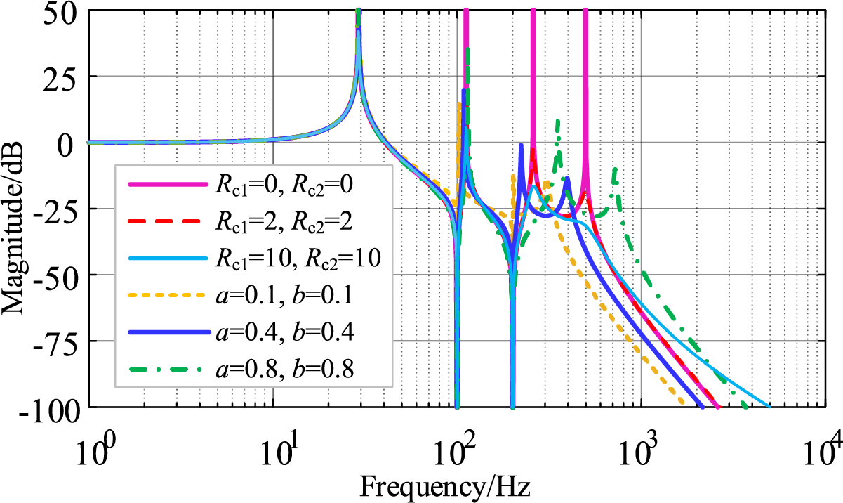
Figure 10: Effect of different RC parameters on filter transfer function
The parameters of the LCLC filter are calculated based on reference [21,22]. In this paper, we focus on the optimal allocation of the total capacitance between the damping branch and the LC resonance branch, where multiple capacitors are shared. As shown in the first section, low-order harmonics on the DC side mainly include the 2nd, 4th, 8th, and 12th harmonics. The LC trap circuit effectively attenuates the 2nd and 4th harmonics. Meanwhile, the distribution ratio of the capacitors primarily affects the 8th and 12th harmonics. To ensure that these components are not amplified by resonance, and that higher-order harmonic attenuation remains within acceptable limits, the ratio of the capacitors must be optimized. To this end, the variations in the amplitudes of the 8th, 12th, and other higher-order harmonics with respect to parameters a and b are analyzed, as shown in Fig. 11a. For better visualization, their projections onto the XY plane are also presented in Fig. 11b.
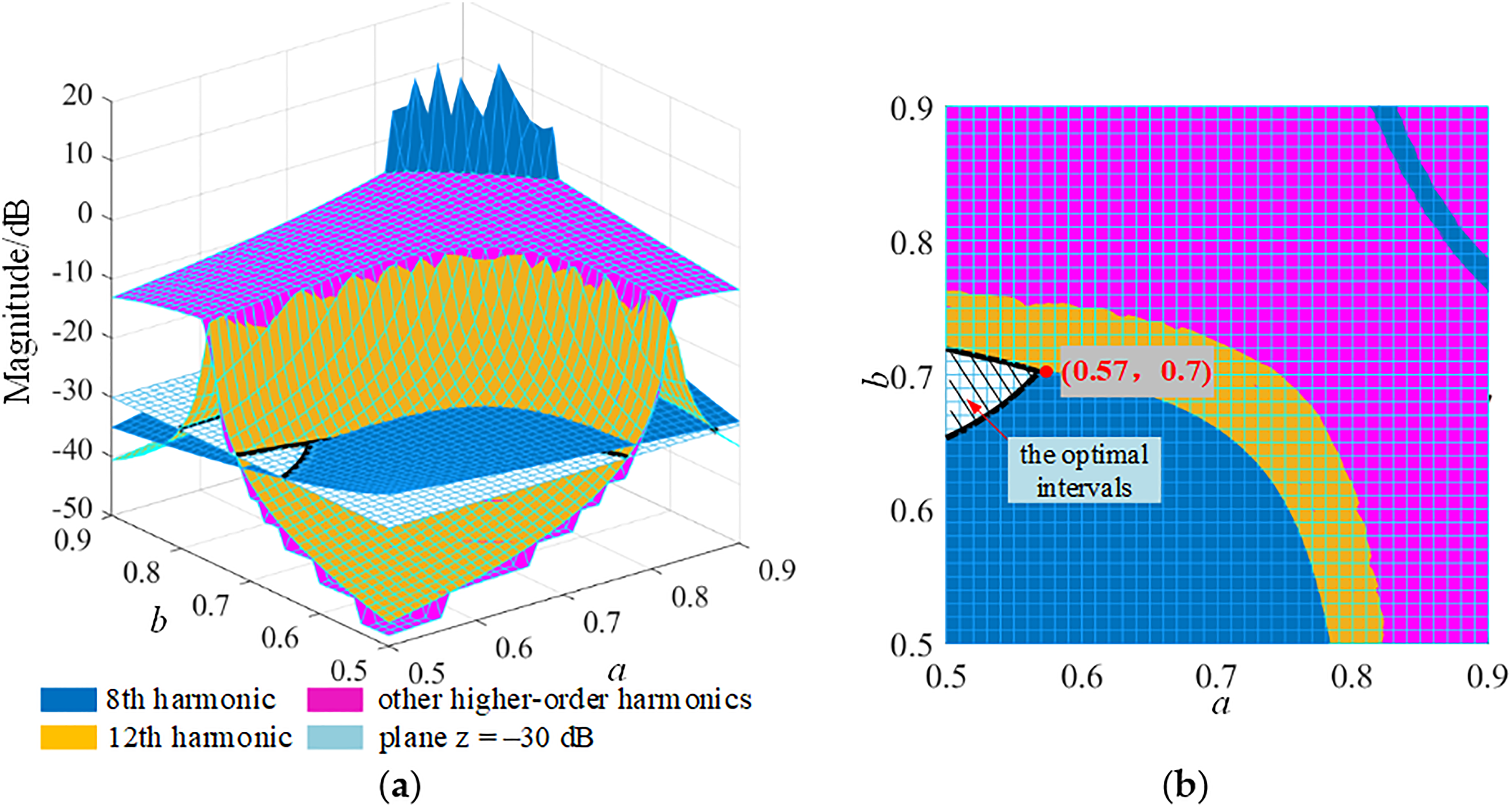
Figure 11: Effect of capacitance ratio on filter transfer function: (a) Amplitude variation of different harmonics; (b) Projection of harmonic amplitude in the XY plane
As observed from the figure, the optimal value intervals are determined by the condition that all harmonic amplitudes above the 8th harmonic are attenuated by more than 30 dB. The intersection of the optimal intervals for parameters a and b yields the final design values: a = 0.57 and b = 0.7.
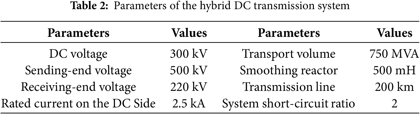
The DC transmission model of the hybrid 12-pulse rectifier and VSC inverter is built based on the MATLAB/Simulink platform. The specific parameters of the model are shown in Table 2.
4.1 Characteristics of the Improved Harmonic Source
Considering a 4% unbalance in the AC grid, Fig. 12 shows the time-domain and frequency-domain waveforms of the improved DC-side harmonic source model of the LCC.
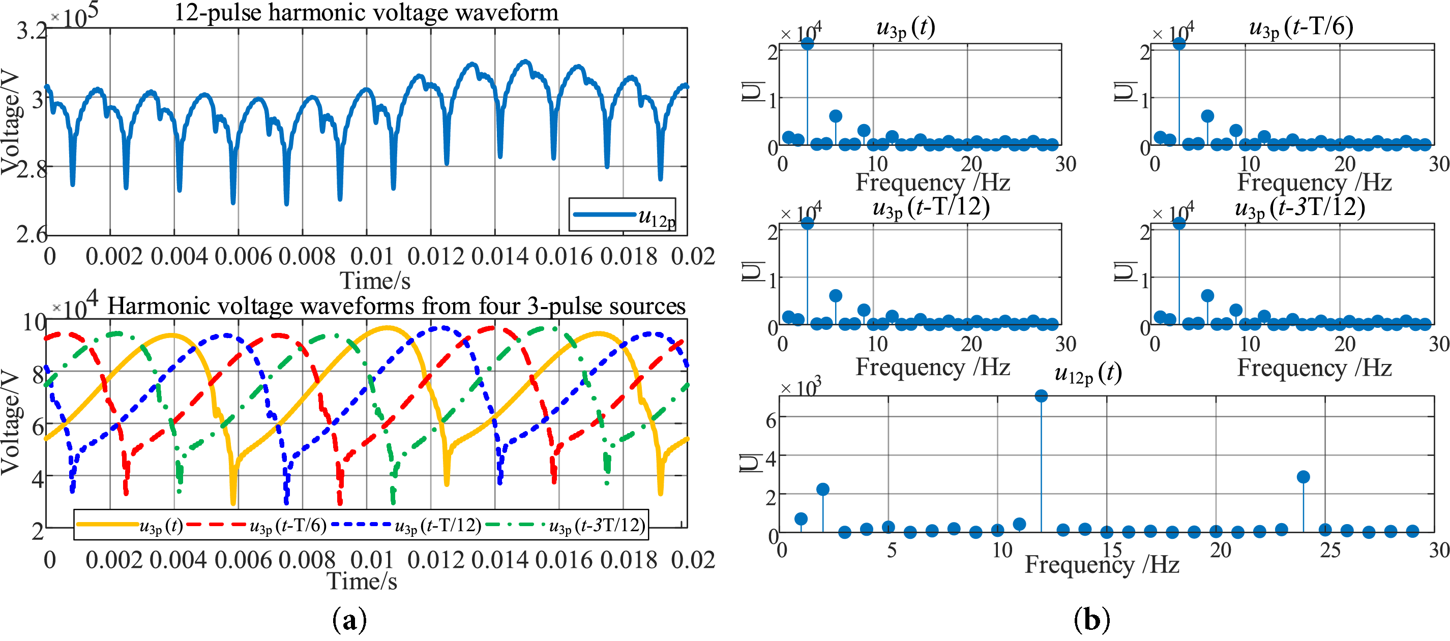
Figure 12: Time-frequency domain waveforms of the improved LCC harmonic source: (a) Time-domain waveform; (b) Frequency domain waveform
It can be observed from the figure that the improved harmonic model effectively simulates the increase in the second harmonic caused by AC imbalance, which is consistent with the analysis presented in the previous section.
4.2 DC-Side Harmonic Behavior after the Application of the Filter Circuit
To compare the filtering effect of the proposed circuit with the LC filter and the Butterworth filter, the output voltages of the three filters and their corresponding FFT results are presented in Fig. 13.
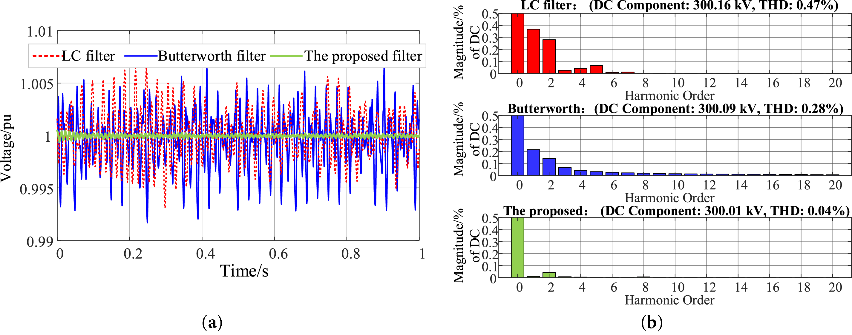
Figure 13: Output voltages of the three filters and their FFT results: (a) Output voltages of different filters; (b) FFT results of the corresponding output voltages
From the figure, it can be observed that the output voltage of the conventional LC filter still contains the fundamental and second harmonic components, with a total harmonic distortion (THD) of 0.47%. In comparison, although the Butterworth filter achieves better attenuation of the fundamental and second harmonics, its THD remains at 0.28%, and some high-order harmonics are still present. By contrast, the filter proposed in this paper effectively eliminates both the second and higher-order harmonics, achieving a THD as low as 0.04%.
4.3 Transient Characteristics Analysis
The system’s transient characteristics are examined under two conditions: (i) a 100 MW load increase at the receiving end at t = 0.2 s, and (ii) a transient DC line fault at t = 0.2 s, cleared by the circuit breaker and reclosed 60 ms after fault clearance. The filter responses under these transients are shown in Fig. 14, and the corresponding harmonic components within the first cycle are summarized in Table 3.

Figure 14: Filter output voltage under different transient conditions
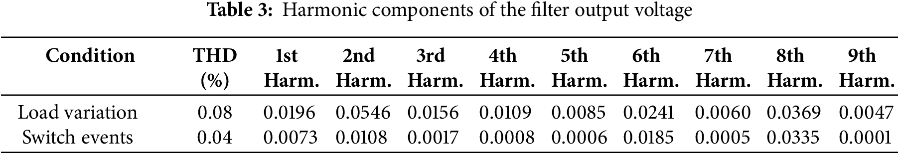
It can be observed that short-term switching caused by transient DC faults has negligible effect on the filter output, while an increase in load induces minor voltage fluctuations. In both cases, the filter output harmonics remain within acceptable limit.
This paper focuses on the detailed analysis of the DC-side harmonic characteristics of the LCC–VSC hybrid DC transmission system and the optimized design of the filter structure parameters. An improved 3-pulsation harmonic source model for the LCC is proposed to address the limitation of traditional models that fail to simulate non-ideal operating conditions. For the inverter-side VSC, harmonic analysis is conducted using the sparse vector method, with the harmonic interactions between the AC and DC sides represented through the path tree constructed from forward and backward generation operations. A filtering design based on the LCLC-Trap2 filter structure with a shunt RC damping circuit is proposed, and its parameters are optimized. A hybrid DC transmission model is built in MATLAB/Simulink to compare the filtering performance of the LC filter, the Butterworth filter, and the proposed filter. The main conclusions are as follows:
(1) The improved 3-pulsation harmonic source model demonstrates strong adaptability for accurately calculating DC-side harmonics under non-ideal conditions, such as AC harmonic distortion and three-phase asymmetry. Analysis shows that the m-fold positive and negative sequence harmonics on the AC side, when modulated by a 12-pulse converter, generate |m – 1| and |m + 1| harmonics on the DC side, respectively.
(2) The harmonic characteristics of the VSC are analyzed using the sparse vector method. The path tree formed by forward and backward generation operations captures the interaction between AC and DC harmonics. Using the symmetrical component method, it is found that under unbalanced operating conditions, significant low-frequency even harmonics—including a prominent second harmonic—emerge on the DC side.
(3) Based on the identified harmonic characteristics, a comparison of different filter structures leads to the adoption of the LCLC-Trap2 filter with a parallel RC damping circuit. Its parameters are optimized to achieve better harmonic suppression. Simulation results from the MATLAB/Simulink model confirm that the proposed filter provides superior performance in attenuating low-order harmonics compared to conventional LC and Butterworth filters. The simulations also indicate that under both load variation and switching operation transients, the system remains stable, and the filter performance meets the required specifications.
Acknowledgement: All authors express gratitude for the support and cooperation provided by their respective institutions.
Funding Statement: This research was funded by the Natural Science Foundation of Chongqing (CSTB2023NSCQ-MSX0279) and the Science and Technology Research Program of Chongqing Municipal Education Commission (KJQN202201119).
Author Contributions: Chunyan Li: Conceptualization, Methodology, Analysis, Software, Writing—reviewing and editing; Luo Li: Data curation, Writing—original draft preparation; Yushuang Li: Analysis, Software; Yong Jia: Data curation, Validation; Wenyan Li: Supervision, Validation, Writing—reviewing and editing. All authors reviewed the results and approved the final version of the manuscript.
Availability of Data and Materials: All relevant data are included within the paper.
Ethics Approval: Not applicable.
Conflicts of Interest: The authors declare no conflicts of interest to report regarding the present study.
References
1. Chen L, Li G, Chen H, Qiao X, Ding M, Hu R, et al. Combinatorial multi-objective optimization of resistive SFCL and DC circuit breaker in hybrid HVDC transmission system. IEEE Trans Appl Supercond. 2021;31(8):5603206. doi:10.1109/TASC.2021.3094430. [Google Scholar] [CrossRef]
2. Jin X, Nian H. Overvoltage suppression strategy for sending AC grid with high penetration of wind power in the LCC-HVdc system under commutation failure. IEEE Trans Power Electron. 2021;36(9):10265–77. doi:10.1109/TPEL.2021.3066641. [Google Scholar] [CrossRef]
3. Shao B, Zhao S, Yang Y, Gao B, Blaabjerg F. Sub-synchronous oscillation characteristics and analysis of direct-drive wind farms with VSC-HVDC systems. IEEE Trans Sustain Energy. 2021;12(2):1127–40. doi:10.1109/TSTE.2020.3035203. [Google Scholar] [CrossRef]
4. Lei S, Shu H, Li Z, Tian X, Wang S. A protection method for LCC-VSC hybrid HVDC system based on boundary transient power direction. Int J Electr Power Energy Syst. 2023;151(3):109138. doi:10.1016/j.ijepes.2023.109138. [Google Scholar] [CrossRef]
5. Dong Y, Ma J, Wang S, Liu T, Chen X, Huang H. An accurate small signal dynamic model for LCC-HVDC. IEEE Trans Appl Supercond. 2021;31(8):0603606. doi:10.1109/TASC.2021.3107804. [Google Scholar] [CrossRef]
6. Mirsaeidi S, Dong X. An enhanced strategy to inhibit commutation failure in line-commutated converters. IEEE Trans Ind Electron. 2020;67(1):340–9. doi:10.1109/TIE.2019.2896328. [Google Scholar] [CrossRef]
7. Liu N, Li Y, Li T, Li S, He J, Dong X. Protection for HVDC transmission lines based on current ratio of DC filter and smoothing reactor. CSEE J Power Energy Syst. 2025;11(4):1625–34. doi:10.17775/CSEEJPES.2021.02330. [Google Scholar] [CrossRef]
8. Takahashi A, Suto T, Fujita H, Hiranuma Y, Ichimura S, Watanabe K, et al. −1 MV DC filter and high-voltage DC measurement system for ITER neutral beam injector system. IEEE Trans Power Electron. 2021;36(7):7587–99. doi:10.1109/TPEL.2020.3041661. [Google Scholar] [CrossRef]
9. Lin S, Mu D, Liu L, Lei Y, Dong X. A novel fault diagnosis method for DC filter in HVDC systems based on parameter identification. IEEE Trans Instrum Meas. 2020;69(9):5969–71. doi:10.1109/TIM.2020.3003362. [Google Scholar] [CrossRef]
10. Maher M, Abdel Aleem SHE, Ibrahim AM, El-Shahat A. Novel mathematical design of triple-tuned filters for harmonics distortion mitigation. Energies. 2023;16(1):39. doi:10.3390/en16010039. [Google Scholar] [CrossRef]
11. Lin S, Mu D, Xu L, He Z. Parameter optimization method for AC filters in HVDC considering reactive power compensation effectiveness. IEEE Trans Power Deliv. 2025;40(1):365–75. doi:10.1109/TPWRD.2024.3495706. [Google Scholar] [CrossRef]
12. Li G, Luo A, He Z, Ma F, Chen Y, Wu W, et al. A DC hybrid active power filter and its nonlinear unified controller using feedback linearization. IEEE Trans Ind Electron. 2021;68(7):5788–98. doi:10.1109/TIE.2020.2996147. [Google Scholar] [CrossRef]
13. Gong C, Sou WK, Lam CS. Observer-based second-order sliding mode current controller for thyristor-controlled LC-coupling hybrid active power filter. IEEE J Emerg Sel Top Power Electron. 2023;11(4):4377–92. doi:10.1109/JESTPE.2022.3198551. [Google Scholar] [CrossRef]
14. Farghly A, El Habrouk M, Ahmed KH, Abdel-khalik AS, Ali Refaat Hamdy R. Active power filter for12-pulse LCC converter employed in LCC-MMC hybrid HVDC system. In: 2022 23rd International Middle East Power Systems Conference (MEPCON); 2022 Dec 13–15; Cairo, Egypt. p. 1–7. doi:10.1109/MEPCON55441.2022.10021735. [Google Scholar] [CrossRef]
15. Ma G, Xie C, Li C, Zou J, Guerrero JM. Passivity-based design of passive damping for LCL-type grid-connected inverters to achieve full-frequency passive output admittance. IEEE Trans Power Electron. 2023;38(12):16048–60. doi:10.1109/TPEL.2023.3313106. [Google Scholar] [CrossRef]
16. Liu Y, Liu J, Wang T, Zhang F, Zheng J, Yin L, et al. High-frequency resonance suppression based on cross-coupled filter and improved passive damper for MMC-HVDC system. IEEE Trans Power Deliv. 2024;39(3):1952–62. doi:10.1109/TPWRD.2024.3387716. [Google Scholar] [CrossRef]
17. Liao J, Zhou N, Wang Q. DC-side harmonic analysis and DC filter design in hybrid HVDC transmission systems. Int J Electr Power Energy Syst. 2019;113(1):861–73. doi:10.1016/j.ijepes.2019.06.013. [Google Scholar] [CrossRef]
18. Mukhopadhyay A, John V. Solid-state tuning restorer for second-harmonic LC filter in single-phase converters. IEEE Trans Ind Appl. 2024;60(1):658–71. doi:10.1109/TIA.2023.3320109. [Google Scholar] [CrossRef]
19. Lee GS, Kwon DH, Moon SI, Hwang PI. Reactive power control method for the LCC rectifier side of a hybrid HVDC system exploiting DC voltage adjustment and switched shunt device control. IEEE Trans Power Deliv. 2020;35(3):1575–87. doi:10.1109/TPWRD.2019.2949906. [Google Scholar] [CrossRef]
20. Lee GS, Kwon DH, Moon SI. DC current and voltage droop control method of hybrid HVDC systems for an offshore wind farm connection to enhance AC voltage stability. IEEE Trans Energy Convers. 2021;36(1):468–79. doi:10.1109/TEC.2020.3005777. [Google Scholar] [CrossRef]
21. Gulur S, Iyer VM, Bhattacharya S. A partially rated LC trap type AC filter for grid-tied voltage source converters. IEEE Open J Power Electron. 2024;5:852–63. doi:10.1109/OJPEL.2024.3408272. [Google Scholar] [CrossRef]
22. Ma G, Xie C, Li C, Peng C, Zou J. Passivity-based design of external passive damper for LCL-type grid-connected inverter. IEEE Trans Power Electron. 2024;39(9):11558–70. doi:10.1109/TPEL.2024.3402124. [Google Scholar] [CrossRef]
Cite This Article
 Copyright © 2025 The Author(s). Published by Tech Science Press.
This work is licensed under a Creative Commons Attribution 4.0 International License , which permits unrestricted use, distribution, and reproduction in any medium, provided the original work is properly cited.
 Downloads
 Citation Tools