
 Submit a Paper
 Propose a Special lssue
 Open Access
ARTICLE
CFD Analysis of Corrugated Plate Designs to Improve Heat Transfer Efficiency in Plate Heat Exchangers
1 Faculty of Engineering Science & Technology, Hamdard University, Madinat al-Hikmah Hakim Mohammed Said Road, Karachi, 74600, Sindh, Pakistan
2 National University of Science & Technology, PNEC Library, PNS JAUHAR, Habib Ibrahim Rahmatullah Road, Karachi, 44000, Sindh, Pakistan
3 Mechanical Engineering Department, Quaid-e-Awam University of Engineering, Science & Technology, Nawabshah, 67480, Sindh, Pakistan
4 Faculty of Mechanical & Automotive Engineering Technology, Universiti Malaysia Pahang Al-Sultan Abdullah, Pekan, 26600, Pahang, Malaysia
5 Centre for Automotive Engineering, Universiti Malaysia Pahang AI Sultan Abdullah, Pekan, 26600, Pahang, Malaysia
6 Centre for Research in Advanced Fluid & Processes, Universiti Malaysia Pahang Al-Sultan Abdullah, Gambang, 26300, Pahang, Malaysia
* Corresponding Author: Kashif Ahmed Soomro. Email:
Energy Engineering 2025, 122(12), 4857-4872. https://doi.org/10.32604/ee.2025.069847
Received 01 July 2025; Accepted 29 September 2025; Issue published 27 November 2025
 View Full Text
 Download PDF
Abstract
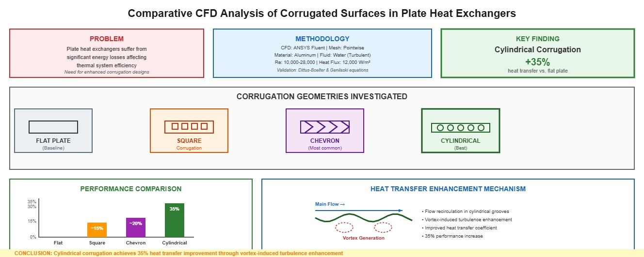
Plate heat exchangers suffer from significant energy losses, which adversely affect the overall efficiency of thermal systems. To address this challenge, various heat transfer enhancement techniques have been investigated. Notably, the incorporation of surface corrugations is widely recognized as both effective and practical. Chevron corrugation is the most employed design. However, there remains a need to investigate alternative geometries that may offer superior performance. This study aims to find a novel corrugation design by conducting a comparative CFD analysis of flat, square, chevron, and cylindrical corrugated surfaces, assessing their impact on heat transfer enhancement within a plate heat exchanger. ANSYS Fluent software was used for simulation at four distinct Reynolds numbers (10,000, 18,000, 26,000, and 28,000), with a heat flux of 12,000 W/m2. A structured mesh was generated using Pointwise software. The material of the solid plates was modelled as aluminum, the fluid was modelled as water, and the flow was turbulent. To obtain a fully developed turbulent flow, a separate inlet duct was modelled, and the output velocity profile of the inlet duct was input into the plate heat exchanger. The Nusselt number (Nu) and heat-transfer coefficient (h) were calculated to evaluate the performance of all surfaces. The results indicate that cylindrical corrugated surfaces exhibit higher Nusselt numbers than chevron, square, and flat plates. This higher performance is because of the generation of vortices in the middle of the cylindrical texture. Consequently, flow recirculation occurs, leading to reattachment to the mainstream flow. This phenomenon induces increased turbulence, thereby enhancing the heat transfer efficiency. To validate the results, a grid-convergence independence test was performed for three different mesh sizes. In addition, empirical calculations were performed using the Dittus-Boelter and the Genilaski equations to validate the results of the flat-plate heat exchanger. It was concluded that the cylinder was the best corrugated surface and had a maximum heat transfer 35% higher than that of a flat plate.Graphic Abstract
Keywords
Heat exchangers are one of the most important equipment that directly affect the overall performance of the industry. They offer a medium to transfer heat from fluid to fluid or solid to fluid [1]. Heat exchangers are frequently used in many Industries such as food industries, HVAC, power plants (renewable, conventional), automobiles, etc. [2]. However, Plate heat exchangers have considerable losses in the form of waste heat, which affects the overall performance of the thermal system [3]. These losses cause the extra consumption of fossil fuels, causing a problem for the environment and climate change [4]. Additionally, these losses increase the overall cost of energy [4]. Therefore, the heat transfer enhancement of plate heat exchangers is under consideration by various researchers [5,6]. Many authors have performed experiments on the different textures to enhance the heat transfer capability. The selection of corrugation shapes in plate heat exchangers plays a critical role in optimizing heat transfer and hydraulic performance. Several studies have explored a variety of geometrical modifications that increase the effective heat transfer area while generating turbulence to disrupt thermal boundary layers. Thereby, enhancing convective heat transfer. Kanaris et al. [7] performed CFD analyses to correlate the performance of corrugated plate heat exchangers with variations in corrugation geometry. Their findings suggest that a change in the geometry causes a performance improvement. Another study conducted by Wang et al. [8] compared various corrugation designs: chevron, asterisk, and flat plate models. They found that the asterisk corrugation introduces unique flow paths, which ultimately augment the heat transfer rate. Similarly, Jiang et al. [9] supported the fact that the asterisk-type plate heat exchanger has enhanced heat transfer and increased pressure drop compared to flat plate exchangers. Another type of corrugation was studied by Kushchev et al. [10], focused on incorporating spherical recesses (akin to dimples) into plate designs. Their numerical simulations revealed that these dimples enhance local turbulence by disrupting the flow, which accelerates heat exchange processes. Likewise, Zhang et al. [11] carried out a study on a plate heat exchanger (PHE) with multi-chevron corrugate furrows and found enhanced heat transfer efficiency. Jin et al. [12] performed the study numerically and investigated the heat transfer performance of three distinct heat exchangers: flat-plate heat exchanger (PHE), wavy-PHE, and zigzag-PHE. Their findings indicate that the wavy-plate heat exchanger (PHE) offers superior heat transfer performance.
A major part of the corrugation study in the literature is related to the study of the chevron angle. Most importantly, studies have been carried out to find the optimum chevron angle for the augmentation of heat transfer. This is evident in the study of Yang and Hsieh [13], who concluded that the modifications in the chevron angle can improve flow boiling heat transfer performance. This conclusion is consistent with the studies [14,15]. Furthermore, the work in [16–18] provided experimental evidence that higher chevron angles boost convective heat transfer. Collectively, these findings underscore the critical importance of optimizing chevron geometry. The interaction between chevron angle, corrugation pitch, and corrugation height has a significant influence on thermal and hydraulic performance. In addition to chevron patterns, various other corrugation geometries have also been investigated. For instance, Júnior et al. [19,20] compared triangular, trapezoidal, and rectangular corrugations. They reported that the triangular corrugations achieved the highest heat transfer rate.
Recent research has broadened the spectrum of studied geometries to include both sinusoidal (wavy) and asymmetric designs. Lee et al. [21] investigated traditional sinusoidal and two unique asymmetric cross-corrugated surfaces. They made a similar conclusion that the geometry of corrugation plays a crucial role in the augmentation of heat transfer. Moreover, studies concentrating on flow visualization and three-dimensional simulations have highlighted the effectiveness of chevrons, herringbones, and similar configurations. These designs not only enhance fluid mixing by creating swirling flows but also aid in reducing boundary layer thickness, thereby enhancing the overall efficiency of the exchanger [22]. Studies incorporating sinusoidal wavy arcs with flat tangential segments [23,24] have identified unique effects on the efficiency of heat exchangers. These investigations demonstrate that each corrugation pattern distinctly affects the thermal and hydraulic characteristics of the exchanger.
Other configurations, such as double-dimpled corrugated shapes, have also been analyzed for their unique ability to generate small swirl zones that foster enhanced heat transfer with moderate pressure losses [25]. This diversity in geometric forms underlines the importance of tailoring the corrugation design to the specific operating conditions, thereby achieving an optimal balance between heat transfer enhancement and pressure drop minimization.
The literature establishes a broad spectrum of corrugation shapes, including triangular, trapezoidal, rectangular, sinusoidal, square, chevron (herringbone), and dimpled profiles offer distinct advantages and limitations. Each of these designs affects the heat transfer process by modifying the fluid flow patterns in unique ways [19–23]. However, few studies focus on the comparison of those shapes with chevron texture, which is already a commonly used texture in the industry. This study compares the novel cylinder texture with the chevron texture through CFD analysis. The analysis demonstrates the superiority of the novel cylinder texture over the conventional chevron texture. This study directly addresses critical gaps in plate heat exchanger (PHE) optimization by rigorously evaluating cylindrical textures—a novel curved-profile design—against angular benchmarks (chevron) under standardized conditions. Therefore, the present work studies different types of textures and compares the heat transfer performance of chevron, square, and cylindrical textures. A numerical and comparative study has been performed for all textures by using water as a working fluid. Initially, SolidWorks was used to develop CAD models, and structured meshing was generated by Gridgen software. Finally, the Ansys Fluent V16 software was used for simulation and analysis.
2.1 Computational Model Formulation
Computational formulations include the three major steps: (1) Preprocessing, (2) Solver, (3) Post processing [26]. The steps are performed and explained in the following sections:
A rectangular inlet duct was modeled with four plate configurations affixed to its base:
1. flat plate (Fig. 1a),
2. cylindrical protrusions (Fig. 1b),
3. half-chevron grooves (Fig. 1c), and
4. square engravings (Fig. 1d).

Figure 1: (a) Geometry of flat plate; (b) Geometry of cylindrical textured plate; (c) Geometry of chevron textured plate; (d) Geometry of squared textured plate (all units are in cm)
Symmetry boundary conditions were imposed, and Mesh optimization followed established practices [27–29].
Structured grids with wall refinement were employed throughout all configurations: the flat plate (Fig. 2a); the cylindrical-textured plate featuring multi-block O-H topology (Fig. 2b,c); the square-textured plate (Fig. 2d); and the chevron-textured plate (Fig. 2e).
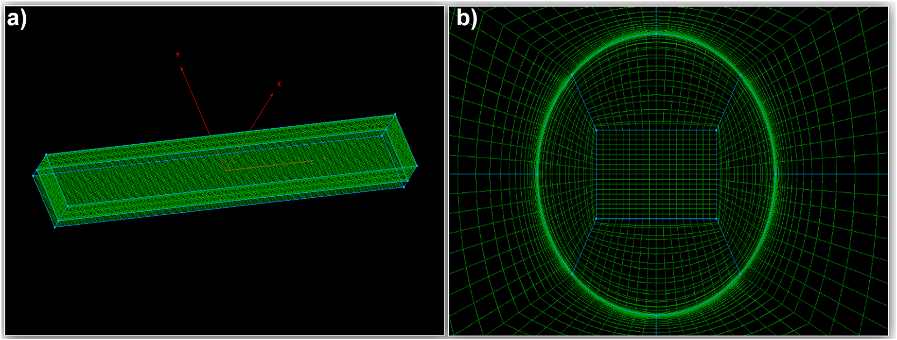

Figure 2: (a) Mesh of flat plate; (b) OH topology mesh in the cylinders; (c) Mesh of cylindrical corrugations; (d) Square corrugations mesh; (e) Chevron corrugations mesh; (f) Boundary conditions
The boundary conditions of the mesh setting in Pointwise software are given in Table 1 and Fig. 2f.

Three-dimensional simulations were performed using ANSYS Fluent® (2024 R1) with the realizable k-ε turbulence model [30]. This model was selected for its robustness in predicting vortex-driven flows induced by surface textures [31–33]. Furthermore, Ai et al. [34] confirmed the model’s reliability by verifying its accuracy against earlier research results. Moreover, Gherasim et al. [35] performed simulations on several turbulence models for corrugated plates in turbulent flow and observed that the realizable model gave predictions closest to experimental results. Similarly, Bai et al. [36] compared standard k–ε and realizable k–ε for plates and established that the realizable k–ε with enhanced wall treatment is more accurate for complex turbulent flows in corrugated geometries. Considering the results of these studies and the suitability of the k-epsilon realizable for complex turbulent flow, the model was used for the analysis.
The governing equations—continuity (Eq. (1)), Navier-Stokes (Eq. (2)), and energy conservation (Eq. (3)) [37–39]—were solved using a pressure-based coupled algorithm. Second-order upwind discretization was applied to momentum, turbulence, and energy terms. Solutions were considered converged at residuals below 10−6 for all variables. Near-wall resolution-maintained y+ < 1 across all configurations to resolve thermal boundary layers. Complete solver parameters are given in Table 2.

3 Equations and Mathematical Expressions
In addition to solving the continuity, Navier–Stokes, and energy conservation equations, empirical correlations by Dittus–Boelter and Gnielinski were utilized for validation purposes, as represented in Eqs. (4), (5) and (5a) [40]. The convective heat transfer coefficient was determined using Newton’s law of cooling (Eq. (6)). Subsequently, the Nusselt number was evaluated based on Eqs. (7) and (7a) [40].
Since the heating and Cooling are considered below
n = 0.4 for heating,
N = 0.3 for cooling
All terms are the same except f = Darcy friction factor. It is calculated by the Pethukhov relation:
Here, Dh is Hydraulic diameter, which is a characteristic length scale used to describe non-circular conduits for fluid flow analysis [33].
4.1 Validation with Empirical Formula
In the present study, the CFD results for the flat plate were validated using empirical correlations, as described in the previous section. The Nusselt number as a function of Reynolds number was calculated using established empirical relations and compared with the CFD predictions. Four Reynolds numbers—10,000, 18,000, 26,000, and 28,000—were used as input for both the Dittus–Boelter and Gnielinski equations. A Prandtl number of 6.99, corresponding to water at atmospheric pressure and 20°C [33], was employed in the calculations. The comparison revealed an average deviation of approximately 15% between the CFD results and the Dittus–Boelter correlation. In contrast, the Gnielinski correlation, which is more accurate and comprehensive than the Dittus–Boelter relation, showed an average deviation of approximately 10% when compared with results obtained from ANSYS Fluent, as shown in Fig. 3. These findings confirm that the current CFD model is reliable and capable of accurately predicting convective heat transfer. The comparative results are presented in Figs. 3 and 4.

Figure 3: CFD vs. empirical relations bar chart

Figure 4: CFD vs. empirical relations
Grid independence, or mesh refinement, is a critical process undertaken to minimize discretization errors and ensure that the numerical solution is not sensitive to the mesh size [41,42]. In this study, three different grid resolutions were selected to perform the grid independence test: a coarse grid with approximately 0.3 million cells, and two finer grids with 0.5 million and 0.7 million cells, respectively. Simulations were carried out for all three mesh sizes at a Reynolds number of 10,000. Velocity was chosen as the representative flow variable for comparison among the different grids to evaluate the mesh dependency of the solution.
As observed in Fig. 5, the velocity results for the different mesh sizes are in close agreement. Notably, the percentage difference between the solutions obtained using the 0.5 million and 0.7 million cell grids is smaller than that between the 0.3 million and 0.5 million cell grids. This indicates that further refinement beyond 0.5 million cells yields only marginal improvements, confirming that the solution is approaching grid independence.

Figure 5: Grid independence test results
Following the completion of simulations, the heat transfer performance of all configurations was evaluated using the Nusselt number as the primary metric. Figs. 6 and 7 present a comparative analysis of the thermal behavior associated with various surface textures. It was found that the Nusselt number and the convective heat transfer coefficient increased with Reynolds number for all cases. The results agree with the study carried out by Krishna et al. [43]. They reported that the overall heat transfer coefficient and Nusselt number in corrugated plate heat exchangers increased with the increase of Reynolds number. This shows that the CFD model is accurate. Furthermore, it is evident from the graphs that the corrugations significantly enhance heat transfer. The study of Shahdad et al. also verifies this result [44]. Their experimental results indicated that the augmentation of heat transfer was due to the increased turbulence induced by the corrugation structure. Similarly, Kargar et al. [45] and Sharma et al. [46] supported the fact that the use of corrugated plates drastically enhanced overall heat transfer coefficients in their experimental calculations.
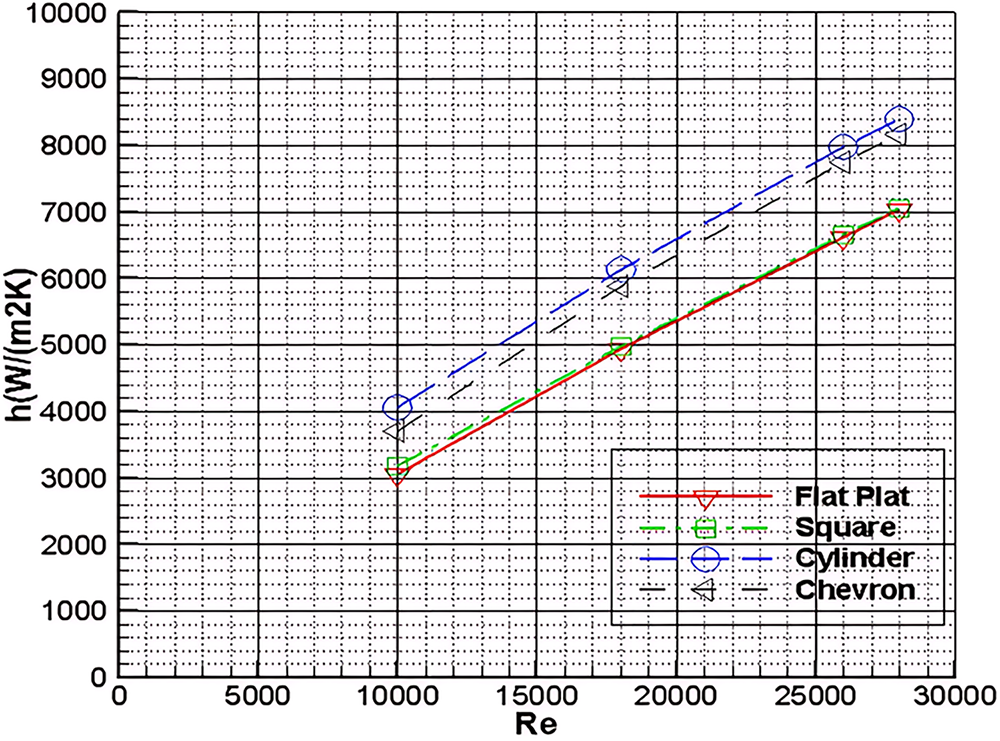
Figure 6: Heat transfer coefficient vs. Reynolds number for all textures

Figure 7: Nusselt number vs. Reynolds number for all textures
It was also found that among the configurations investigated, the cylindrical textured heat exchanger demonstrated the most significant enhancement in thermal performance. The superior performance of the cylindrical texture can be attributed to the distinct flow behaviors induced by its geometry. These textures promote flow disturbances that lead to the formation of vortices. Specifically, vortices generated at the center, along with vortex pairs near the texture edges, substantially increase the local eddy diffusivity of both momentum and thermal energy. Furthermore, reattachment zones observed in the contour plots indicate the generation of secondary flows, which also contribute to heat transfer enhancement. These secondary flows, particularly prominent at the downstream end of the cylindrical textures, are responsible for the highest Nusselt number observed among all configurations. A similar finding has been reported by Nameer et al. [47]. Who performed experiments related to different corrugations and found that cylinder texture is better in performance than all other textures. Although their study was conducted under different conditions, the agreement in trends provides qualitative validation for the present results.
Furthermore, the cylindrical texture exhibited a Nusselt number approximately 35% higher than that of the flat plate configuration, confirming its superior performance. The chevron texture followed closely, with a heat transfer rate about 5% lower than that of the cylindrical case. In contrast, the square texture was comparatively less effective. Overall, the results confirm the potential of cylindrical surface textures as the most effective corrugation for the enhancement of heat transfer.
The contour plot illustrates the considerable impact of corrugations on the thermal efficiency of a plate heat exchanger. The periodic bulging of velocity and temperature contours near the corrugation is a direct result of the corrugated design, as illustrated in Figs. 8 and 9. It can be easily visualized that the corrugations not only expand the effective surface area but also disrupt the thermal boundary layer. As a result, the local turbulence is generated, and secondary flows such as vortices are produced. This greater fluid movement disturbs the otherwise stable temperature layers near the walls, as shown in the contour of plate heat exchangers in Figs. 8a and 9a. Hence, stronger mixing between the hotter and cooler fluid regions is observed. Consequently, heat transfer is augmented. Therefore, the corrugations significantly increase heat transfer by combining increased surface area with induced turbulent mixing, which would be absent in a smooth channel configuration.

Figure 8: Velocity contours of (a) Flat plate; (b) Cylinder texture; (c) Square texture; (d) Chevron texture

Figure 9: Temperature contour of (a) Flat plate; (b) Cylinder texture; (c) Square texture; (d) Chevron texture and magnified view of temperature contour of (e) Cylinder texture; (f) Chevron texture
Fig. 9 presents the temperature contours obtained from CFD simulations for four different plate surface configurations in a plate heat exchanger: (a) flat plate, (b) cylinder texture, (c) square texture, and (d) chevron texture. The flat plate (a) serves as the baseline and shows a smooth, laminar thermal profile with a gradual temperature gradient from inlet to outlet. Due to the absence of surface disruptions, there is limited mixing and minimal turbulence, resulting in lower heat transfer efficiency. In contrast, the cylinder-textured plate (b) introduces localized flow separation and recirculation zones around each protrusion, leading to enhanced convective heat transfer at those specific regions. The overall thermal performance improves slightly compared to the flat surface, though the effect remains spatially confined.
The square texture (c) further intensifies heat transfer by generating stronger vortices and flow disturbances due to its sharp edges. Finally, the chevron texture (d), which mimics industrial plate heat exchanger designs, produces the second most effective thermal performance. This results in a well-distributed temperature profile, higher heat transfer rates, and reduced thermal stratification. Overall, among the four configurations, the cylinder-textured plate demonstrates the highest heat transfer efficiency, followed by chevron, square, and flat plates.
For better understanding and visualization of fluid flow, streamlines of all cases were generated. The streamline plot clearly illustrates the complex flow behavior caused by the corrugations in the plate heat exchanger illustrated in Fig. 10. This further highlights the rise of a substantial recirculation zone just downstream of a corrugation. The streamlines reveal a distinct vortex structure. In this vortex structure, the flow detaches from the surface, circulates in a loop, and eventually reattaches further downstream. This process of flow separation and reattachment is a symbol of enhanced convective transport. This is because it increases mixing between fluid layers and disrupts the thermal and velocity boundary layers. These flow structures are crucial for improving overall heat transfer efficiency. Hence, the streamlines effectively demonstrate how the corrugated geometry enhances heat exchange performance.

Figure 10: Streamlines of (a) Flat plate; (b) Cylindrical texture; (c) Square and (d) Cheron
This study presents a detailed investigation into the effects of surface texturing on the convective heat transfer performance of a plate heat exchanger, employing high-resolution computational fluid dynamics (CFD) simulations and validation through empirical correlations. Three surface textures, including square, chevron, and cylindrical, were evaluated and compared with a baseline smooth plate configuration. Among the studied configurations, the cylindrical texture demonstrated the most significant enhancement, achieving a Nusselt number approximately 35% higher than that of the smooth plate.
The enhanced thermal performance observed with the cylindrical texture is primarily attributed to the formation of flow-induced vortices, vortex pairs near the texture edges, and downstream flow reattachment zones. These flow structures promote intensified local mixing and elevate the eddy diffusivity of both momentum and thermal energy, thereby facilitating more effective convective heat transfer.
Validation of the CFD model against empirical correlations confirmed the accuracy and reliability of the numerical approach. The CFD-predicted Nusselt numbers showed an average deviation of approximately 15% from the Dittus–Boelter correlation and about 10% from the Gnielinski correlation. In addition, a grid independence study was conducted, which demonstrated consistent results across three mesh sizes, reinforcing the robustness of the simulation methodology.
In conclusion, the findings of this study highlight the critical influence of surface texture geometry on the thermal performance of plate heat exchangers. The cylindrical texture emerged as a highly effective configuration for heat transfer enhancement. These insights lay a strong foundation for future research focused on geometric optimization of textured surfaces for high-performance, energy-efficient heat exchanger applications in industrial systems.
Acknowledgement: The authors truly acknowledge the support and research facility provided by PNEC, National University of Science and Technology, Islamabad, Pakistan, and the Mechanical Engineering Department, Hamdard University, Karachi, Pakistan.
Funding Statement: The authors received no specific funding for this study.
Author Contributions: The authors confirm contribution to the paper as follows: Conceptualization, Kashif Ahmed Soomro and S. R. Qureshi; Methodology, Kashif Ahmed Soomro and S. R. Qureshi; Software, Kashif Ahmed Soomro and Rahool Rai; Validation, Sudhakar Kumarasamy, Rahool Rai and Kashif Ahmed Soomro; Formal analysis, Kashif Ahmed Soomro and Rahool Rai; Investigation, Kashif Ahmed Soomro and S. R. Qureshi; Data curation, Kashif Ahmed Soomro and Rahool Rai; Writing—original draft preparation, Kashif Ahmed Soomro and Rabiya Jamil; Writing—review and editing, Kashif Ahmed Soomro, Sudhakar Kumarasamy, Rahool Rai and Rabiya Jamil; Visualization, Kashif Ahmed Soomro and Rahool Rai; Supervision, S. R. Qureshi and Abdul Hameed Memon; Project administration, S. R. Qureshi and Abdul Hameed Memon. All authors reviewed the results and approved the final version of the manuscript.
Availability of Data and Material: The authors confirm that the data supporting the findings of this study are available within the article.
Ethics Approval: Not applicable.
Conflicts of Interest: The authors declare no conflicts of interest to report regarding the present study.
Abbreviations
| Nu | Nusselt Number |
| Pr | Prandtl Number |
| Re | Reynold number |
| f | Darcy friction factor |
| U | Velocity vector (U, V, W) (m/s) |
| ∇⋅U | Divergence of velocity (rate of volume expansion) (s−1) |
| ρ | Fluid Density (kg/m3) |
| ∂u/∂t | Local (unsteady) acceleration (m/s2) |
| u·∇u | Convective acceleration (m/s2) |
| ∇p | Pressure gradient (Pa/m (N/m3)) |
| μ | Dynamic viscosity (Pa·s) |
| ∇2 | Laplacian of velocity (viscous diffusion) m/s2 |
| F | Body force per unit volume (e.g., gravity) N/m3 (kg/m2·s2) |
| h | Specific Enthalpy (j/kg) |
| ∇h | Gradient of enthalpy J/kg·m |
| k | Thermal conductivity (w/m·k) |
| t | Temperature (k) |
| φ | Viscous dissipation (W/m3) |
| s | Heat source per unit volume (w/m3) |
| A | Area of heat transfer (m2) |
| T2 | Final temperature (K) |
| T1 | Initial temperature (K) |
| Dh | Hydraulic diameter (m) |
| PHE | Plate Heat Exchanger |
References
1. Borjigin S, Zhao W, Fu W, Liang W, Bai S, Ma J, et al. Review of plate heat exchanger utilized for gases heat exchange. Renew Sustain Energy Rev. 2025;210(13):115224. doi:10.1016/j.rser.2024.115224. [Google Scholar] [CrossRef]
2. Subbiah M. The characteristics of brazed plate heat exchangers with different chevron angles. In: Mitrovic J, editor. Heat exchangers—basic design applications. Rijeka, Croatia: InTech; 2012. p. 397–424. doi:10.5772/32888. [Google Scholar] [CrossRef]
3. Durmuş A, Benli H, Kurtbaş İ, Gül HH. Investigation of heat transfer and pressure drop in plate heat exchangers having different surface profiles. Int J Heat Mass Transf. 2009;52(5–6):1451–7. doi:10.1016/j.ijheatmasstransfer.2008.07.052. [Google Scholar] [CrossRef]
4. Raghuvanshi N, Johri A, Saxena M, Kumar A, Gori Y. Economic and environmental aspects of heat exchanger applications. In: Heat exchanger technologies for sustainable renewable energy systems. Boca Raton, FL, USA: CRC Press; 2025. p. 158–89. doi:10.1201/9781003534785-9. [Google Scholar] [CrossRef]
5. Khail AA, Erişen A. Heat transfer and performance enhancement investigation of novel plate heat exchanger. Therm Sci Eng Prog. 2022;34(1–2):101368. doi:10.1016/j.tsep.2022.101368. [Google Scholar] [CrossRef]
6. Rai R, Mangi FH, Ahmed K, Kumaramsay S. Enhancing solar photovoltaic efficiency: a computational fluid dynamics analysis. Energy Eng. 2025;122(1):1–14. doi:10.32604/ee.2024.051789. [Google Scholar] [CrossRef]
7. Kanaris A, Mouza A, Paras S. Flow and heat transfer prediction in a corrugated plate heat exchanger using a CFD code. Chem Eng Technol. 2006;29(8):923–30. doi:10.1002/ceat.200600093. [Google Scholar] [CrossRef]
8. Wang D, Liang Z, Zhou J, Wang H. The simulation research on the performance of the chevron-type corrugated plate heat exchanger. Adv Mater Res. 2011;383–390:6502–7. doi:10.4028/www.scientific.net/AMR.383-390.6502. [Google Scholar] [CrossRef]
9. Jiang C, Zhou W, Tang X, Bai B. Influence of capsule length and width on heat transfer in capsule-type plate heat exchangers. Adv Mech Eng. 2019;11(12):1687814019895742. doi:10.1177/1687814019895742. [Google Scholar] [CrossRef]
10. Kushchev L, Melkumov V, Voronov V, Savvin N. Modeling the heat exchange process in the plate device. Russ J Build Constr Arch. 2023;4(60):6–18. doi:10.36622/VSTU.2023.60.4.001. [Google Scholar] [CrossRef]
11. Zhang J, Zhou N, Zhang G, Tian M. Numerical and experimental studies of flow and heat transfer characteristics in a plate heat exchanger with multi-chevron corrugate furrows. Numer Heat Transf A. 2022;84(1):71–82. doi:10.1080/10407782.2022.2105076. [Google Scholar] [CrossRef]
12. Jin Y, Li M, Cui J, Li Z. Study on the thermal performance of the cross-flow plate heat exchangers. Numer Heat Transf Part A Appl. 2025;86(12):4104–24. doi:10.2139/ssrn.4610346. [Google Scholar] [CrossRef]
13. Yang C, Hsieh M. Flow boiling heat transfer in a plate heat exchanger with mixed chevron angle plates. J Phys Conf Ser. 2024;2766(1):012145. doi:10.1088/1742-6596/2766/1/012145. [Google Scholar] [CrossRef]
14. Nogueira É. Theoretical analysis of the influence of the chevron inclination angle on the thermal performance of a gasket plate heat exchanger. Acta Polytech. 2022;62(6):627–38. doi:10.14311/AP.2022.62.0627. [Google Scholar] [CrossRef]
15. Nogueira É. Influence of the Chevron inclination angle on the thermal performance of a gasket plate heat exchanger. Editora. 2024;62(6):861–90. doi:10.14311/ap.2022.62.0627. [Google Scholar] [CrossRef]
16. Lee H, Sadeghianjahromi A, Kuo P, Wang C. Experimental investigation of the thermofluid characteristics of shell-and-plate heat exchangers. Energies. 2020;13(20):5304. doi:10.3390/en13205304. [Google Scholar] [CrossRef]
17. Lee H, Lee S. Effect of secondary vortex flow near contact point on thermal performance in the plate heat exchanger with different corrugation profiles. Energies. 2020;13(6):1328. doi:10.3390/en13061328. [Google Scholar] [CrossRef]
18. Zhu X. Relationship between chevron angle and heat transfer performance of plate heat exchangers. Case Stud Therm Eng. 2025;69:106032. doi:10.1016/j.csite.2025.106032. [Google Scholar] [CrossRef]
19. Júnior S, Coelho P, Scalon V. Numerical investigation of three-dimensional natural convection heat transfer on corrugated plates of variable height. Int J Numer Methods Heat Fluid Flow. 2024;34(4):1858–83. doi:10.1108/HFF-10-2023-0591. [Google Scholar] [CrossRef]
20. Júnior S, Coelho P, Scalon V, Oliveira S. Numerical and experimental study of natural convection heat transfer on flat and corrugated plates. Int J Numer Methods Heat Fluid Flow. 2023;33(9):3286–307. doi:10.1108/HFF-03-2023-0132. [Google Scholar] [CrossRef]
21. Lee J, Doo J, Min J, Ha M, Son C. Study on the turbulence model sensitivity for various cross-corrugated surfaces applied to matrix-type heat exchanger. J Mech Sci Technol. 2016;30(3):1363–75. doi:10.1007/s12206-016-0243-1. [Google Scholar] [CrossRef]
22. Torii S. Flow visualization and thermal-fluid flow phenomenon in single plate heat exchanger with various plate shapes formed by shock processing method. Mater Sci Forum. 2011;673:35–9. doi:10.4028/www.scientific.net/MSF.673.35. [Google Scholar] [CrossRef]
23. Elsobki A, Fouad Y, Zewail T, Zaatout A, El-Ashtoukhy E, Abdel-Aziz M, et al. Solid-liquid mass transfer of an array of separated parallel corrugated plates. Chem Eng Technol. 2022;45(12):2195–202. doi:10.1002/ceat.202200198. [Google Scholar] [CrossRef]
24. Pandey S, Nema V. Investigation of the performance parameters of an experimental plate heat exchanger in single phase flow. Int J Energy Eng. 2012;1(1):19–24. doi:10.5923/j.ijee.20110101.04. [Google Scholar] [CrossRef]
25. Al-Obaidi A. Comparative investigation of novel thermo-hydraulic flow characteristics and augmentation of heat efficiency in 3D pipes based on parametrical corrugated shape configurations. Heat Transf. 2025;54(3):2165–83. doi:10.1002/htj.23286. [Google Scholar] [CrossRef]
26. Joshi JB, Nandakumar K, Patwardhan AW, Nayak AK, Pareek V, Gumulya M, et al. Computational fluid dynamics. In: Advances of computational fluid dynamics in nuclear reactor design and safety assessment. Cambridge, UK: Woodhead Publishing; 2019. p. 21–238 doi:10.1016/b978-0-08-102337-2.00002-x. [Google Scholar] [CrossRef]
27. Şahin M, Öztürk M. CFD analysis of the characteristic of a heat exchanger with counter flow shell tube under biogas-nanofluid conditions. J Therm Anal Calorim. 2025;17(12):1–10. doi:10.1007/s10973-025-14276-8. [Google Scholar] [CrossRef]
28. Wang E, Sun G, Wang Y, Dai X, Chen W, Liu Z, et al. CFD simulation and optimization study on the shell side performances of a plate and shell heat exchanger with double herringbone plates. Therm Sci Eng Prog. 2023;43(3):101931. doi:10.1016/j.tsep.2023.101931. [Google Scholar] [CrossRef]
29. Rao Y, Feng Y, Li B, Weigand B. Experimental and numerical study of heat transfer and flow friction in channels with dimples of different shapes. J Heat Transf. 2015;137(3):031901. doi:10.1115/1.4029036. [Google Scholar] [CrossRef]
30. Tang X, Zhu D. Experimental and numerical study on heat transfer enhancement of a rectangular channel with discontinuous crossed ribs and grooves. Chin J Chem Eng. 2012;20(2):220–30. doi:10.1016/s1004-9541(12)60382-6. [Google Scholar] [CrossRef]
31. Gorman J, Bhattacharyya S, Cheng L, Abraham PJ. Turbulence models commonly used in CFD. In: Applications of computational fluid dynamics simulation and modeling. London, UK: IntechOpen; 2022. doi:10.5772/intechopen.99784. [Google Scholar] [CrossRef]
32. Lienhard JHIV, Lienhard JH V. A heat transfer textbook. 3rd ed. Cambridge, MA, USA: Phlogiston Press; 2008. [Google Scholar]
33. Cengel YA, Ghajar AJ. Heat and mass transfer: fundamentals and applications. 4th ed. New York, NY, USA: McGraw-Hill; 2011. [Google Scholar]
34. Ai S, Sun C, Liu Y, Li Y. Numerical simulation on JAG-type corrugated plate flow heat transfer characteristics considering physical property changes and shell heat transfer. Case Stud Therm Eng. 2024;53(2):103898. doi:10.1016/j.csite.2023.103898. [Google Scholar] [CrossRef]
35. Gherasim I, Galanis N, Nguyen C. Heat transfer and fluid flow in a plate heat exchanger. Part II: assessment of laminar and two-equation turbulent models. Int J Therm Sci. 2011;50(8):1499–511. doi:10.1016/j.ijthermalsci.2011.03.01. [Google Scholar] [CrossRef]
36. Bai C, Zhang G, Qiu Y, Leng X, Tian M. A new method for heat transfer and fluid flow performance simulation of plate heat exchangers. Numer Heat Transf Part B Fundam. 2019;75(1):1–18. doi:10.1080/10407790.2019.1607117. [Google Scholar] [CrossRef]
37. Sazhin SS. Computational fluid dynamics: an introduction for mechanical engineering students. 1st ed. Cham: Springer; 2025. 172 p. doi:10.1007/978-3-031-86373-8. [Google Scholar] [CrossRef]
38. Valentino MI, Tran LV, Ricklick M, Kapat JS. A study of heat transfer augmentation for recuperative heat exchangers: comparison between three dimple geometries. J Eng Gas Turbines Power. 2012;134(7):072303. doi:10.1115/1.4005990. [Google Scholar] [CrossRef]
39. Arya H, Sarafraz MM, Pourmehran O, Arjomandi M. Heat transfer and pressure drop characteristics of MgO nanofluid in a double pipe heat exchanger. Heat Mass Transf. 2019;55(6):1769–81. doi:10.1007/s00231-018-02554-1. [Google Scholar] [CrossRef]
40. Bejan A. Convection heat transfer. 4th ed. New York, NY, USA: Wiley; 2013. 658 p. doi:10.1002/9781118671627. [Google Scholar] [CrossRef]
41. Eça L, Hoekstra M. A procedure for the estimation of the numerical uncertainty of CFD calculations based on grid refinement studies. J Comput Phys. 2014;262(1):104–30. doi:10.1016/j.jcp.2014.01.006. [Google Scholar] [CrossRef]
42. Li W, Ji L, Agarwal RK, Shi W, Zhou L. Brief review of computational fluid dynamics. In: Li W, Ji L, Agarwal R, Shi W, Zhou L, editors. Mixed-flow pumps: modeling, simulation, and measurements. Oxford, UK: ASME-Wiley; 2024. p. 21–46. doi:10.1115/1.862mfp_ch3. [Google Scholar] [CrossRef]
43. Krishna M, Swamy M, Manjunath G, Rao N, Rao B, Murthy P. Heat transfer enhancement in corrugated plate heat exchanger. Br J Appl Sci Technol. 2016;18(3):1–14. doi:10.9734/bjast/2016/28438. [Google Scholar] [CrossRef]
44. Shahdad I, Fazelpour F. Numerical analysis of the surface and geometry of plate fin heat exchangers for increasing heat transfer rate. Int J Energy Environ Eng. 2018;9(2):155–67. doi:10.1007/s40095-018-0270-z. [Google Scholar] [CrossRef]
45. Kargar A, Salarizadeh M, Niazi A. Thermal performance of corrugated plate heat exchanger: experimental and numerical investigation. Int J Heat Mass Transf. 2020;161(1):120279. doi:10.1016/j.ijheatmasstransfer.2020.120279. [Google Scholar] [CrossRef]
46. Sharma A, Gupta A, Tyagi S. Performance enhancement of heat exchangers with corrugated plates: a review. Chem Eng Sci. 2019;203(5):41–56. doi:10.1016/j.ces.2019.01.030. [Google Scholar] [CrossRef]
47. Nameer SA, Saeed MS, Ali A. An experimental comparison of different textured surfaces for heat transfer enhancement. Imp J Interdiscip Res. 2016;2(12):816–22. [Google Scholar]
Cite This Article
 Copyright © 2025 The Author(s). Published by Tech Science Press.
This work is licensed under a Creative Commons Attribution 4.0 International License , which permits unrestricted use, distribution, and reproduction in any medium, provided the original work is properly cited.
 Downloads
 Citation Tools