
 Submit a Paper
 Propose a Special lssue
 Open Access
REVIEW

The Electric Vehicle Surge: Effective Solutions for Charging Challenges with Advanced Converter Technologies
1 Sustainability Group, Cyient Ltd., Pune, 411057, India
2 Department of Electronics and Communication Engineering, K.S.R.M. College of Engineering, Kadapa, 516003, India
3 Department of Electrical and Electronics Engineering, K.S.R.M. College of Engineering, Kadapa, 516003, India
4 Mobility Group, Eaton India Innovation Center LLP, Pune, 411028, India
* Corresponding Author: Rajanand Patnaik Narasipuram. Email:
Energy Engineering 2025, 122(2), 431-469. https://doi.org/10.32604/ee.2025.055134
Received 18 June 2024; Accepted 20 December 2024; Issue published 31 January 2025
 View Full Text
 Download PDF
Abstract
The global adoption of Electric Vehicles (EVs) is on the rise due to their advanced features, with projections indicating they will soon dominate the private vehicle market. However, improper management of EV charging can lead to significant issues. This paper reviews the development of high-power, reliable charging solutions by examining the converter topologies used in rectifiers and converters that transfer electricity from the grid to EV batteries. It covers technical details, ongoing developments, and challenges related to these topologies and control strategies. The integration of rapid charging stations has introduced various Power Quality (PQ) issues, such as voltage fluctuations, harmonic distortion, and supra-harmonics, which are discussed in detail. The paper also highlights the benefits of controlled EV charging and discharging, including voltage and frequency regulation, reactive power compensation, and improved power quality. Efficient energy management and control strategies are crucial for optimizing EV battery charging within microgrids to meet increasing demand. Charging stations must adhere to specific converter topologies, control strategies, and industry standards to function correctly. The paper explores microgrid architectures and control strategies that integrate EVs, energy storage units (ESUs), and Renewable Energy Sources (RES) to enhance performance at charging points. It emphasizes the importance of various RES-connected architectures and the latest power converter topologies. Additionally, the paper provides a comparative analysis of microgrid-based charging station architectures, focusing on energy management, control strategies, and charging converter controls. The goal is to offer insights into future research directions in EV charging systems, including architectural considerations, control factors, and their respective advantages and disadvantages.Keywords
Nomenclature
| CDD | Capacitor-Diode-Diode |
| CDR | Current Doubler Rectifier |
| CF-DAB | Current-Fed Dual-Active-Bridge |
| DAB | Dual-Active-Bridge |
| EV | Electric Vehicles |
| ESU | Energy Storage Units |
| FCML | Flying Capacitor Multilevel |
| FCS | Fast Charging Station |
| FCV | Fuel Cell Vehicle |
| HEV | Hybrid Electric Vehicle |
| IBC | Interleaved Boost Converter |
| MI | Modulation Index |
| MLC | Multilevel Converter |
| MV | Medium Voltage |
| NPC | Neutral Point Clamped |
| PEV | Plug-in Electric Vehicle |
| PFC | Power Factor Correction |
| PWM | Pulse Width Modulation |
| PQ | Power Quality |
| PS-DFB | Phase-Shift Dual-Full-Bridge |
| PSFBC | Phase Shifted Full Bridge Converter |
| RES | Renewable Energy Sources |
| SC | Switched Capacitor |
| SMES | Superconducting Magnetic Energy Storage |
| SNPC | Stacked Neutral-Point-Clamped |
| SPA | Saturation Prevention Algorithm |
| SPS | Single-Phase-Shift |
| SRM | Switched Reluctance Motor |
| SVM | Space Vector Modulation |
| THD | Total Harmonic Distortion |
| V2/G | Vehicle-to-Grid |
| VDPC | Virtual Direct Power Control |
| ZVS | Zero Voltage Switching |
Industry, academia and government are collaborating to create a transmission system for EV vehicles that is connected to the grid due to the growing environmental concerns raised by daily transportation. The consumption of fossil fuels will be greatly reduced as a result [1,2]. Over the past several years, overall sales of EV and publicly accessible fast and slow charging stations have expanded [3]. The lack of widespread EV adoption is still a result of economic, technological, and legislative barriers. Major roadblocks to the EV development include high battery costs, reliability difficulties, driving constraints, and complex charging infrastructure [4]. For achieving consistent and affordable operation, a proper power converter topology and using modern control techniques are also crucial. However, utilities may be obliged to make improvements to the current infrastructure before their intended cycle because of a sudden rise in load if EV charging is not handled [5]. While EV chargers have the potential to generate detrimental harmonics that diminish the quality of power [6]. However, this issue can be mitigated through the implementation of harmonic adjustment technology in the charger’s AC to DC power stage [7,8]. EV charger designs, development, and control are related to battery lifetime and charging speed, they must be taken into account when creating dc fast charging infrastructure.
An ideal EV charger should have higher efficiency, power density, low cost and weight. Additionally, grid current should be drawn at a high power factor to ensure the greatest possible availability of real power, and THD (Total Harmonic Distortion) should be kept at the IEE standard level. A variety of charging technology has been discussed in the review [9–11]. In [12], authors analysed EV market analysis as well as EV charging infrastructure specifications. The aforementioned texts do not, however, describe control methods or power converter topologies. The converters with on-board EV chargers was provided in [13] with relation to electrical machines. In [14], reference discussed the high-level supervisory controls, low-level energy management controls, and overviews of energy storage systems inside of EVs. Because they offer low power range in reference [15], so it is not appropriate for DC rapid charging. To decrease the PQ issues, 3ϕ converters are utilised. In [16], they are described. In [17], reference provided a complete analysis for on and off-board chargers that support both power flows. The study in [18] offered incredibly thorough insights into circuit architectures for both rectifier and converter. Additionally, reference [19] offers a fantastic summary of MV (Medium Voltage) ultra-fast chargers based on transformer. On the contrary, does not mention any control mechanisms. The review papers described above cover a wide range of EV charging-related subjects, but they fall short in providing technical description, a comparison of power converter topologies, and an analysis of the DC fast charger control strategies. A literature review of multiport EV chargers that integrate solar power, energy storage, the grid, and EVs has not been located.
Additionally, the concept of wireless, or inductive, EV charging has emerged as a transformative and modern solution, presenting an innovative alternative to conventional wired charging systems. This technology has garnered substantial attention and research focus over the past few years due to its potential to revolutionize the EV charging landscape. Wireless EV charging operates based on the principle of electromagnetic induction, utilizing two main components: a charging pad or ground-based coil, referred to as the primary coil, and a receiver pad installed on the EV, known as the secondary coil. When the EV is parked over the charging pad, an alternating current is applied to the primary coil, generating a magnetic field. It offers convenience and ease of use as there are no physical connectors to handle, making it a more user-friendly option. Drivers can simply park their EV over a charging pad, and the charging process initiates automatically, reducing the need for manual intervention. This is particularly beneficial for autonomous and self-parking EVs, where the entire charging process can be automated. Additionally, inductive charging technology can be embedded within roadways, such as parking lots or even highways, creating a dynamic charging infrastructure for on-the-go replenishment. It offers a solution to range anxiety, as EVs can charge opportunistically during stops or while in traffic. Despite these advantages, there are challenges to overcome, including efficiency loss during power transfer, the need for standardization, and the cost of deploying charging infrastructure. However, wireless EV charging represents an exciting and promising avenue for the future of electric mobility, providing a glimpse into a world where charging is as seamless as parking and driving [20]. As the technology continues to advance and gain wider adoption, it will likely play a pivotal role in the ongoing electrification of transportation [21–25].
Fast charging station installation may cause serious problems like power quality degradation, supraharmonics, grid stability degradation, voltage deviations and reliability issues if it is not planned for or controlled adequately. This study includes an examination of EVs equipped with converters to address issues with power quality. The remaining text is organised in the manner shown below: In Section 2, the characteristics of the EV charging system are displayed. Section 3 gives a description of EV charging technologies and it’s current state. Section 4 illustrates the topologies and controls for the rectifier and converter. The effects on the grid are detailed in Section 5. In Section 6, the review is completed with future scope.
2 EV Charging System Characteristics
The main idea behind EVs is to switch from internal combustion engines, which emit no pollutants, to battery-powered electric motors. Vehicles with fuel cells, plug-in hybrids, and battery power are all types of electric vehicles. When there is less demand for electricity, the grid is used to charge EVs. During these times, coal, solar, wind, and other conventional and renewable energy sources may all be used to produce electricity. FCVs are not actually producing any pollutants because they run on hydrogen as their fuel.
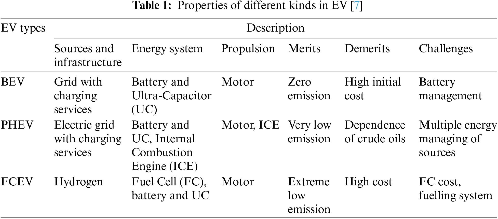
Fuel cell-only vehicles have some drawbacks, including a huge power unit with a poor power response, a spacious interior, and a high price [26]. As a result, FC-HEV (Fuel Cell-Hybrid EVs) is created, offering additional flexibility to improve fuel efficiency and vehicle performance [27–31]. It should be noted that the development of FC-HEV is significantly influenced by the overall power management challenge. EV, HEV, and FCV properties are displayed in Table 1.
3 Topologies and Control for AC to DC Conversion Stage
This section provides a comprehensive technical overview of different front-end AC to DC rectifier topologies. It also delves into a discussion of rectifier topologies specifically tailored for DC quick charging applications.
A technical comparison of three-phase buck rectifier (3ph-BR) is also provided in Table 2. An enhanced 3ph-BR technique was developed in [32] to lessen the voltage demand on the transistors. The following is the equation for the duty ratio of the three legs
where, 3ϕ input voltages are in the sequence are expressed as
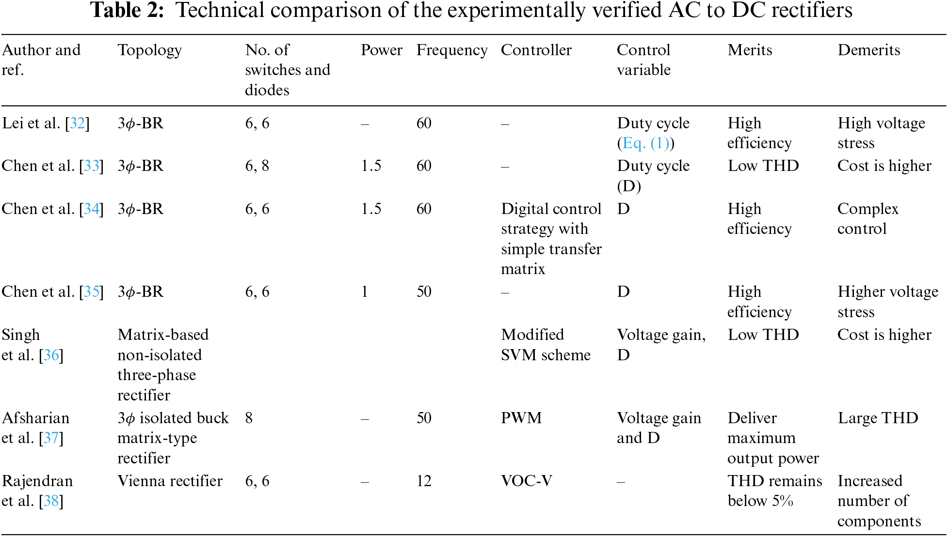
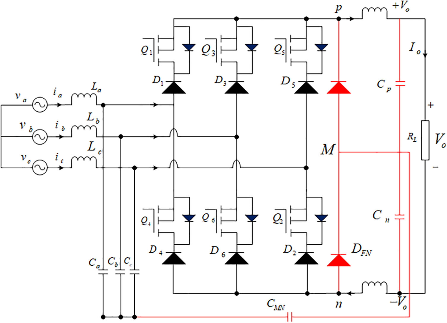
Figure 1: Topology of the 3ϕ-BR [33]
Reference [36] provided a description of a three-phase non-isolated converter utilizing a Current Doubler Rectifier (CDR) circuit. The matrix-based converter is illustrated in Fig. 2. For a three-phase isolated buck matrix-type rectifier operating with a single-phase loss, new Pulse Width Modulation (PWM) schemes and commutation mechanisms were introduced in reference [37]. Additionally, in reference [38], a voltage-oriented control technique was presented, which incorporates a current control loop with rapid transient response and steady-state response. Vienna rectifier with a VOC controller is shown in Fig. 3.
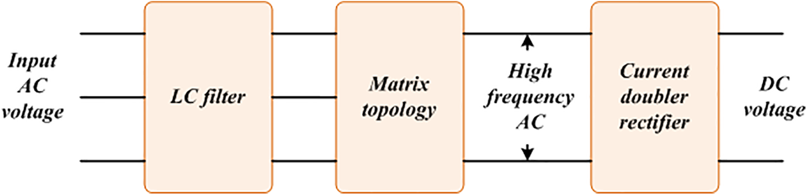
Figure 2: Matrix-based AC to DC converter block diagram [36]
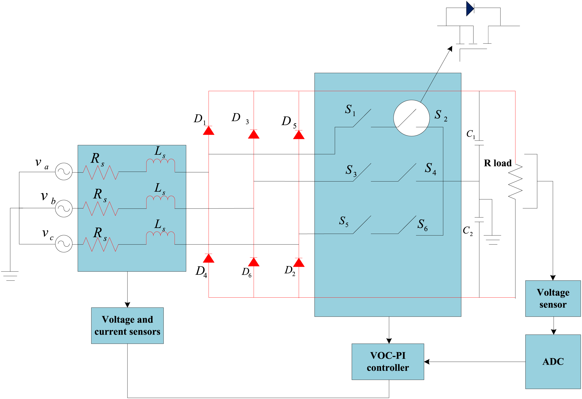
Figure 3: Vienna rectifier with a VOC controller [38]
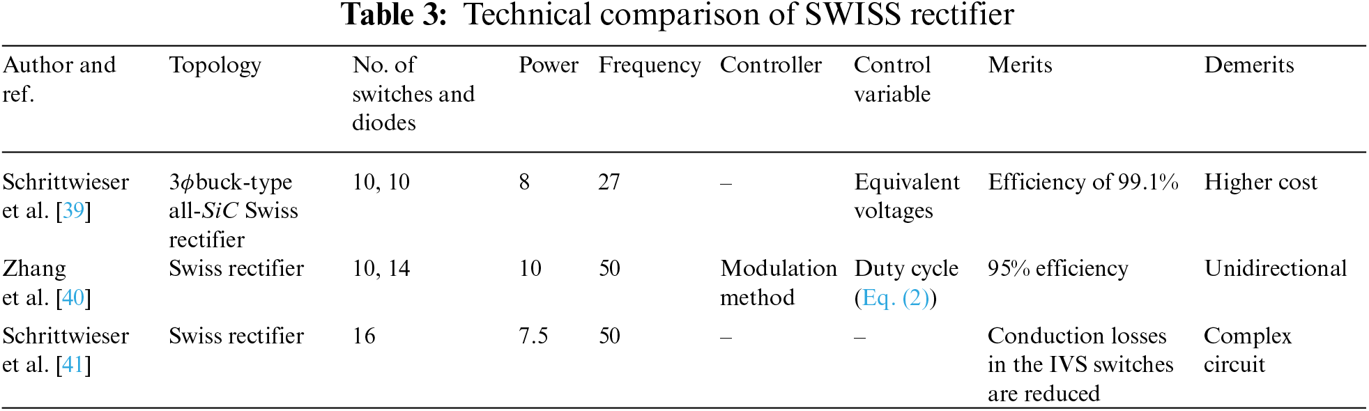
Table 3 provides a technical comparison of the SWISS rectifier. The analysis in Schrittwieser et al. [39] focuses on the comparison between the three-phase bridge rectifier (3ph-BR) with unity power factor and the SWISS Rectifier. It demonstrates how interleaving significantly reduces the Total Harmonic Distortion (THD) of the input current.The following is the duty cycle
where,
Table 4 presents a technical comparison of Vienna rectifiers. Zhang et al. [42] provided a description of neutral point voltage with replicate clamping modes for the same subsector. The following equation represents the Vienna rectifier modulation index
where,
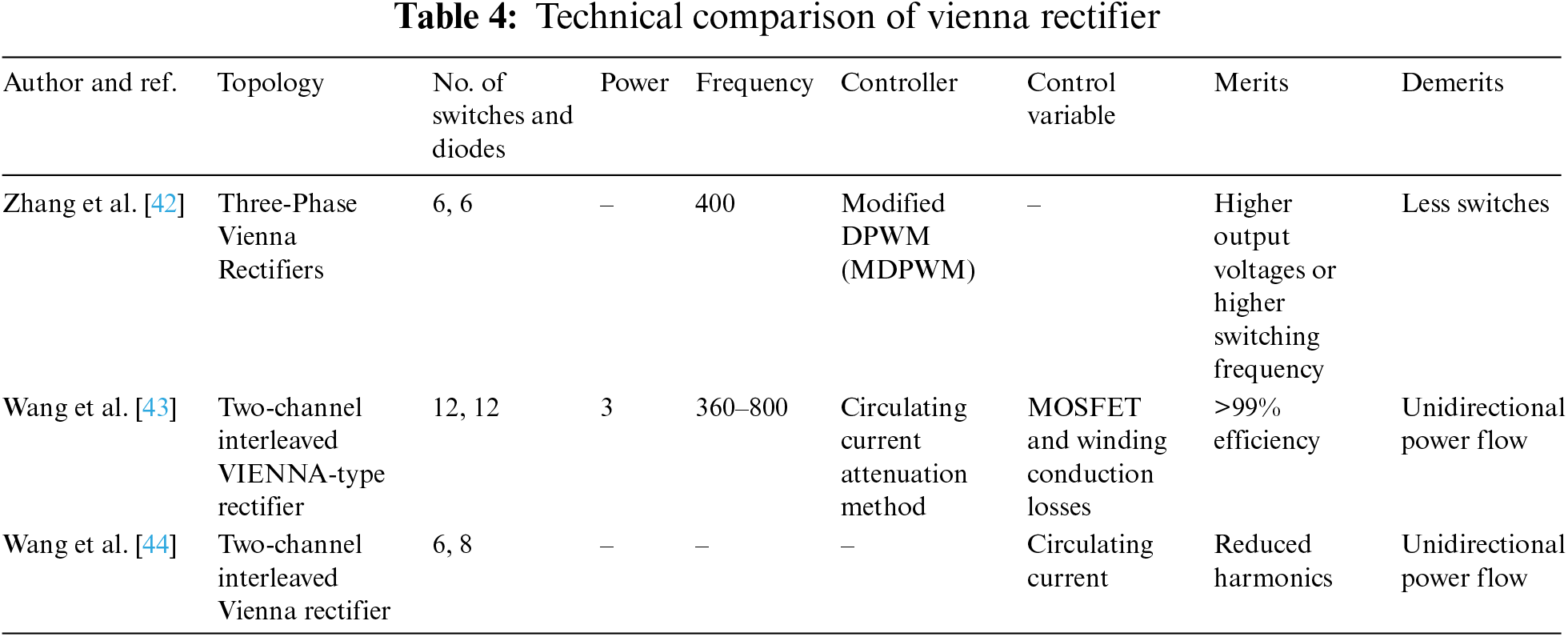
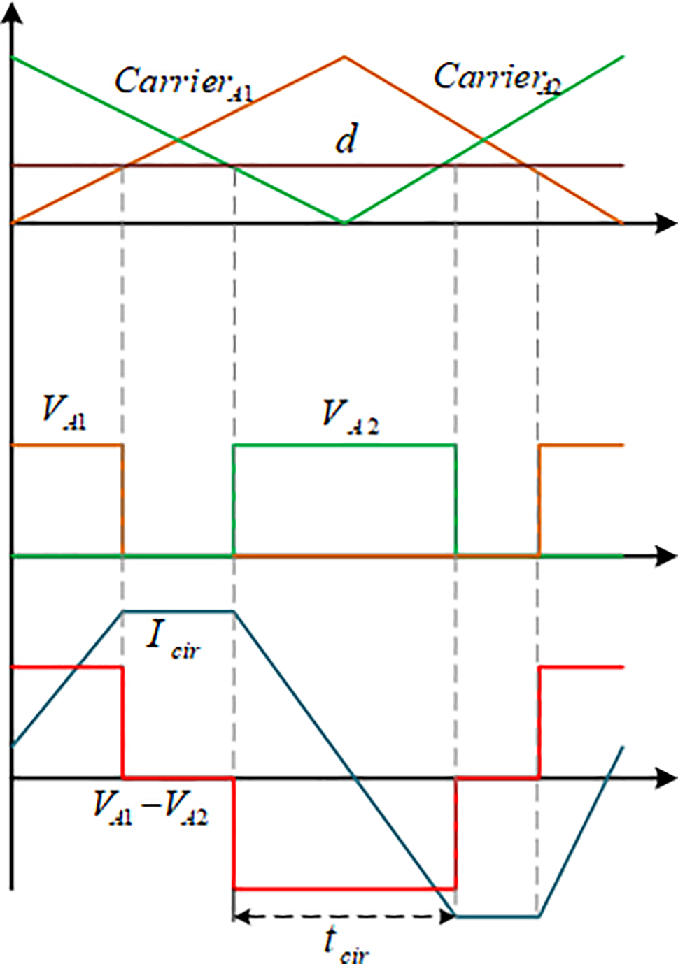
Figure 4: Correlation between output voltage and circulating current [43]
In order to mitigate PQ issues within the system, Wang et al. [44] introduced a two-channel interleaved Vienna rectifier hybrid Space Vector Modulation (SVM) approach.
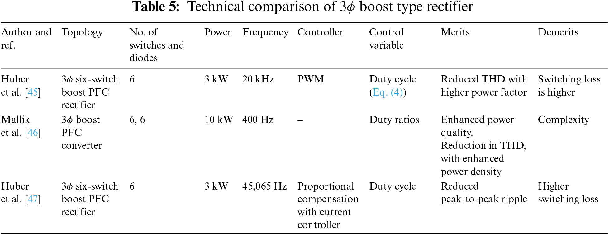
Table 5 presents a technical comparison of three phase boost type rectifiers. The 3ϕ 6-switch boost PFC rectifier with average-current-controlled method was implemented using a 3-step PWM approach in [45].
where,
where, current controlleroutput signals denotes
The Multilevel Converter (MLC) is frequently utilized in research for generating varying voltage levels from multiple lower-level direct current voltages. Based on the various architectural designs found in the literature, MLC can be categorized into three groups due to its capacity to deliver high power with enhanced efficiency and power density. The primary operating principle of an MLC converter involves the use of switches, capacitors, and voltage sources to produce a staircase waveform at the output.
Table 6 displays a technical comparison of the cascaded H Bridge. For multilevel converters, a simplified SVM (Space Vector Modulation) technique was created in [48]. The following steps to find the corresponding duty cycles
where,
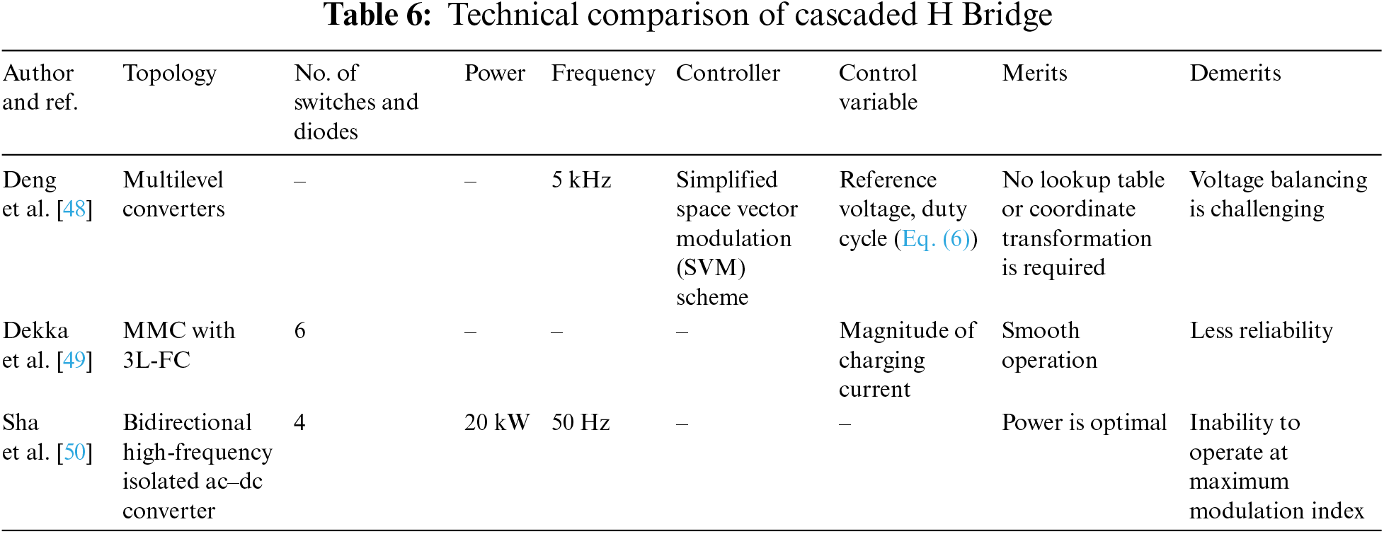
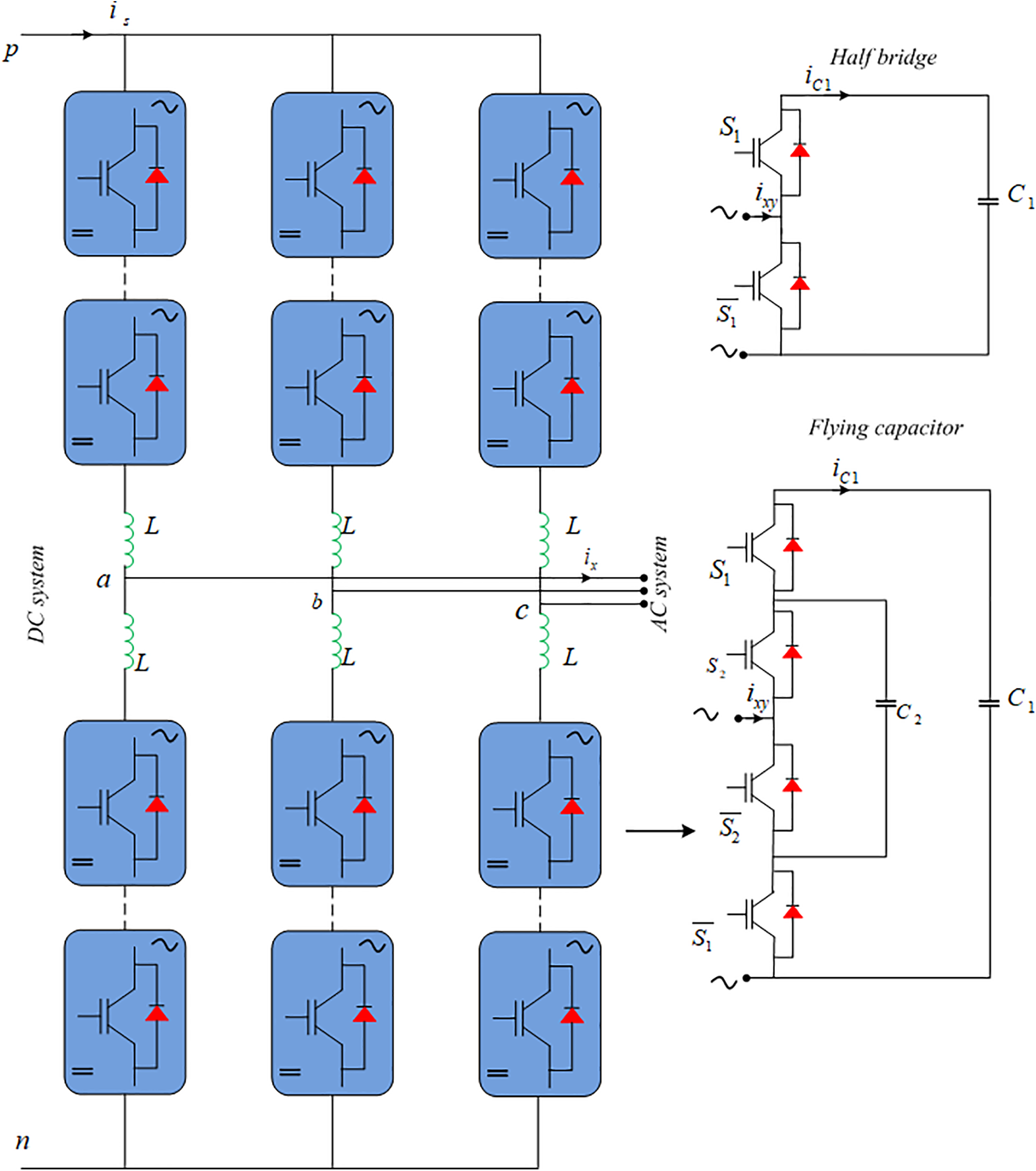
Figure 5: MMC with 3L-FC sub module [49]
Reference [50] describes a vehicle-to-grid (V2G) structure in EV chargers with bidirectional high frequency isolated converter.
Table 7 provides a technical comparison of flying capacitors. The underlying cause of the performance gap between single-phase, DC-link converters was discovered in [51]. Reference [52] showed a power converter with FCML (flying capacitor multilevel) boost converter with a 7-level front end for power factor correction (PFC) was introduced in [53]. Measured performance is shown in Fig. 6.
where, output voltage is specified as
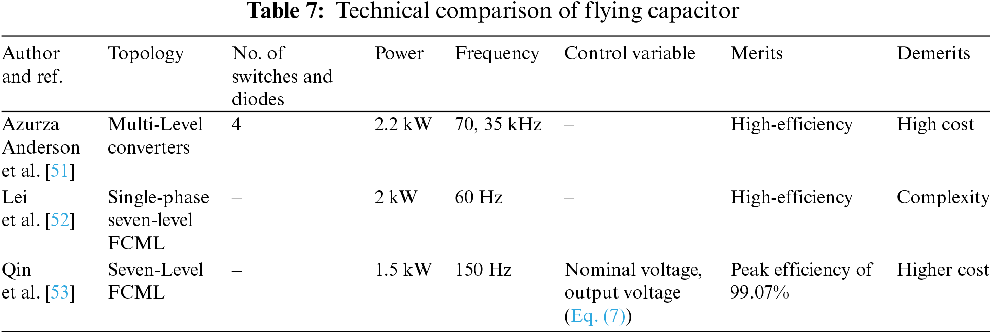
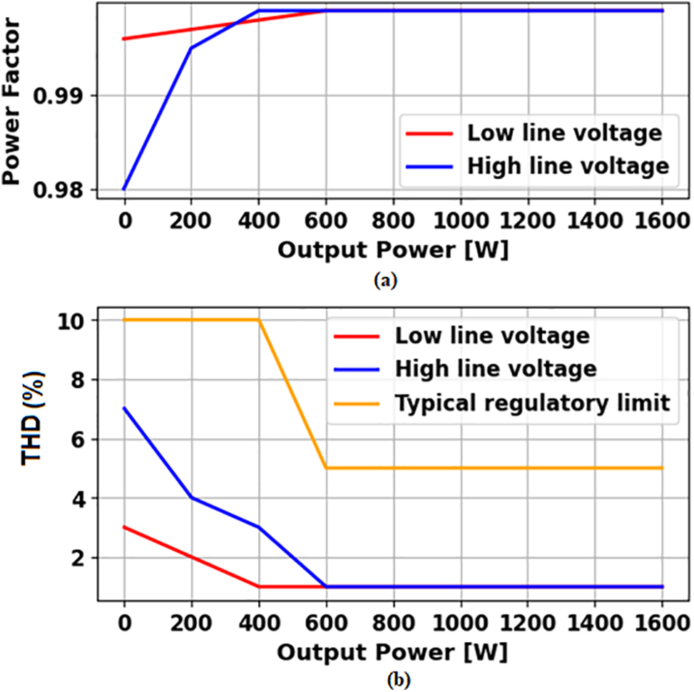
Figure 6: Measured performance under low, high line voltage and typical regulatory limit
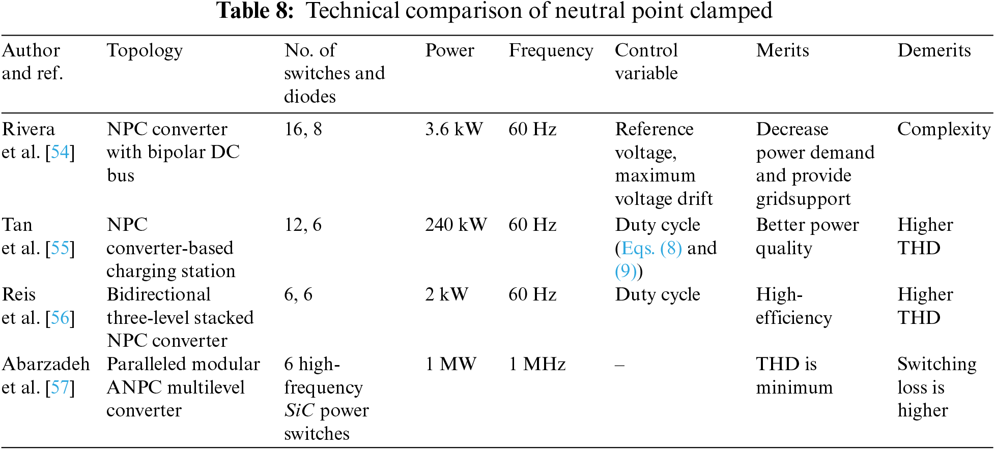
Table 8 presents a technical comparison of neutral point clamped (NPC) converters. In reference [54], an innovative architecture for megawatt-scale plug-in EV (PEV), based on NPC converters, was introduced. Additionally, reference [55] introduced a high-power TL (Three-Level) converter for rapid charging, along with an efficient VBC (Voltage Balancing Control) and a new modulation technique. The modulation signals used in these systems are derived using specific methods.
where,
4 Topologies and Control for DC to DC Converter
Details of DC to DC converter are suitable for DC quick off-board chargers such as isolated and non-isolated, are analysed.
Table 9 displays a technical comparison of LLC Resonant. In [58], new modular multilevel converter (MLC) architecture for a 1 MHz, 1 MW EV mega-charger was developed. An interleaved type converter with cascaded based circuits was introduced in [59] for PEV batteries. For on-board chargers of EV, a hybrid converter with 3 modes of operation was discovered in [60]. The graph for the research is plotted in the Fig. 7.
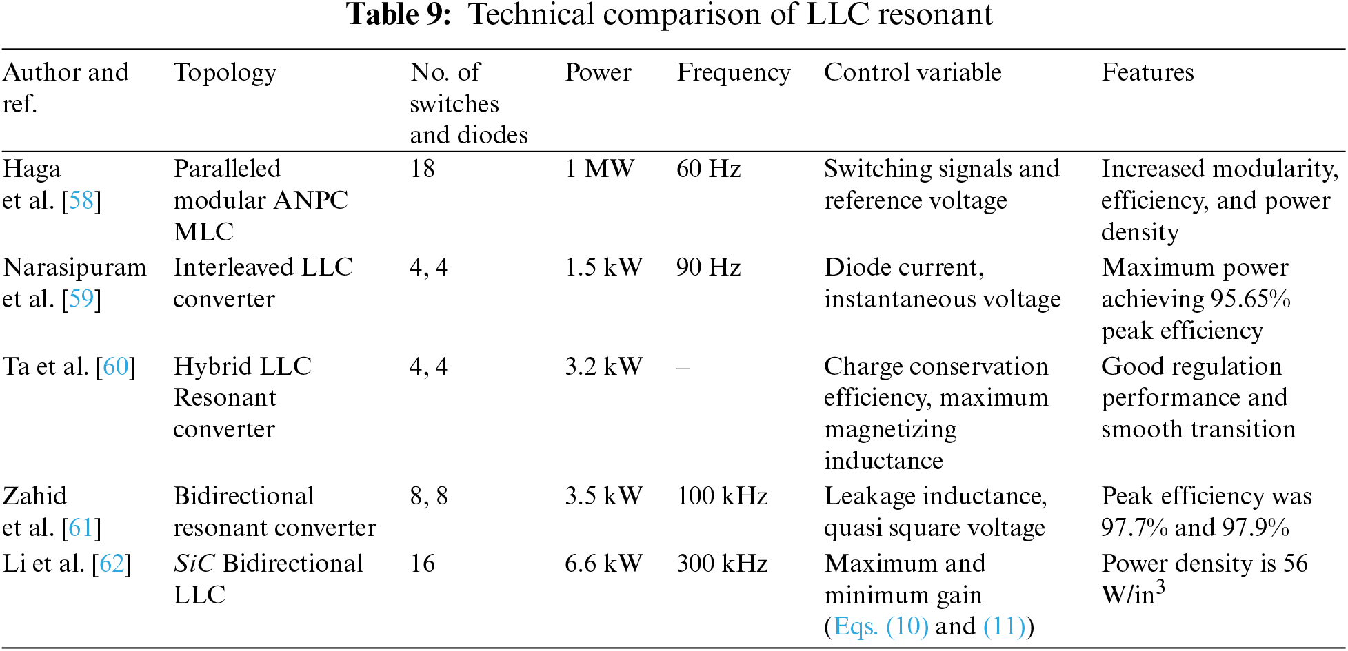
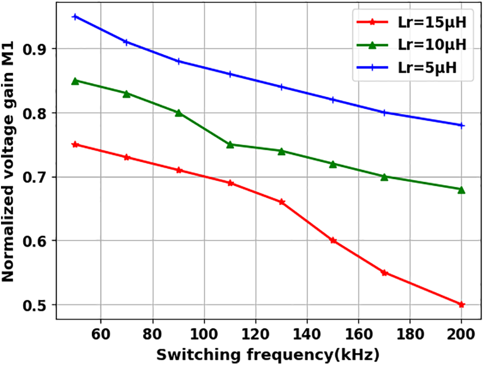
Figure 7: Graph depicting the relationship between switching frequency and normalized voltage gain [60]
A design of bidirectional converter for charging the EV battery was provided in the reference [61]. Fig. 8 depicts the bidirectional resonant converter circuit topology. Architecture based on the SiC bidirectional LLC charger was described in [62] for obtaining high efficiency and power density.
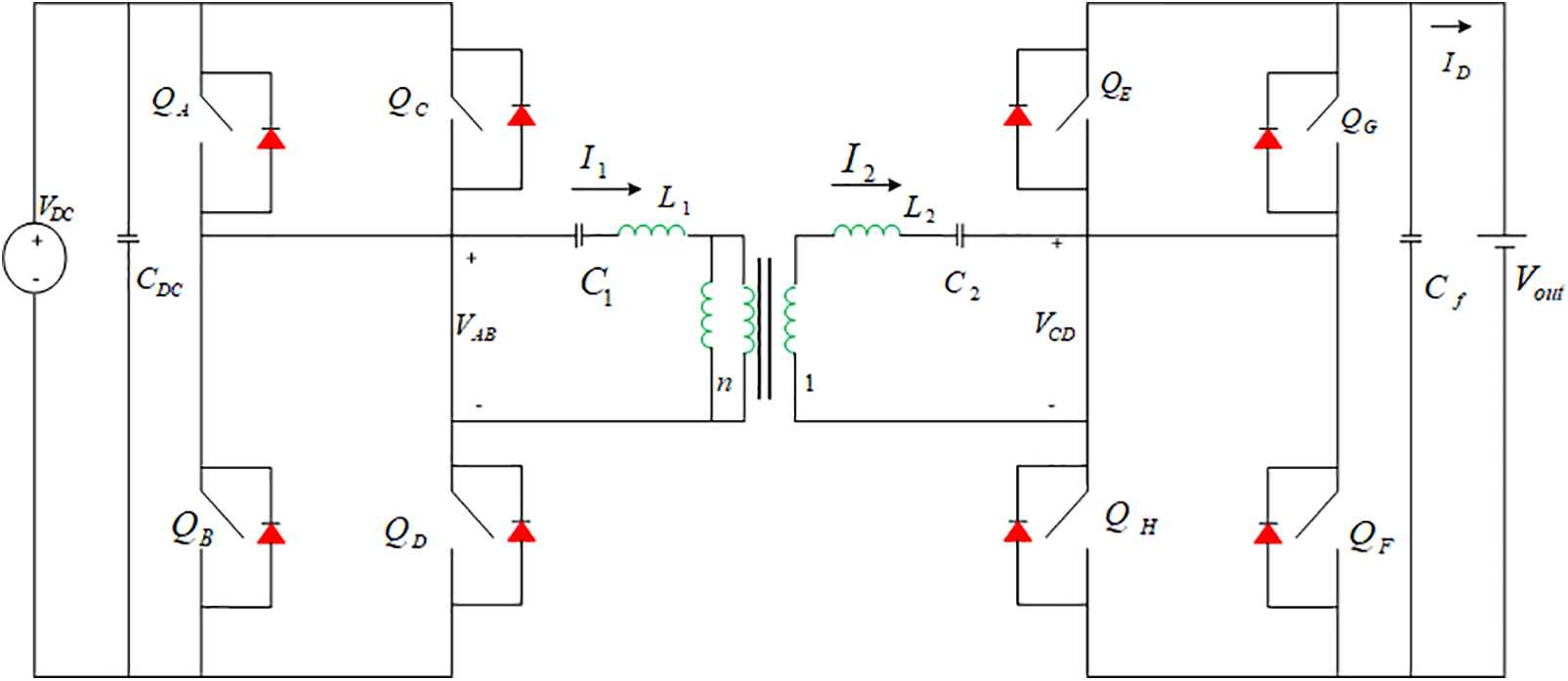
Figure 8: Circuit topology for bidirectional resonant converter [61]
where,
Table 10 provides a technical comparison of Dual-Active-Bridge (DAB) converters. In reference [63], the integration of various configurations was carefully executed to maximize system power while utilizing the Zero Voltage Switching (ZVS) range for both static and dynamic operations in EV chargers. Dead band control was employed in conjunction with ZVS boundary setup. Furthermore, reference [64] introduced a transformer saturation prevention algorithm (SPA) using DAB converters in bi-directional, two-stage EV chargers. Additionally, reference [65] presented a three-level DAB converter designed for bidirectional EV chargers, featuring blocking capacitors.The following equation represents the voltage ratio
where, number of turns is indicated as
Figure 9: 3ϕ DAB converter topology
Reference [67] presents the development of a Phase-Shift DFB (PS-DFB) with two outputs wired in series for EVs. In reference [68], the operation of a Current-Fed DAB (CF-DAB) converter was optimized for a Photovoltaic (PV) application with the aim of increasing system efficiency. Sha et al. [69] introduced a phase-shifted control and a symmetrical dual Pulse Width Modulation (PWM) DC to DC converter featuring a Semi-Active Bridge (S-DAB). A fundamental and universally applicable concept for DAB converter throughout its entire operating range was implemented in reference [70]. To address PQ issues, reference [71] introduced a VDPC (Virtual Direct Power Control) approach with SPS (Single-Phase-Shift) control for DAB DC to DC converters. The following derivation gives the phase shift ratio
where,
Table 11 displays a technical comparison of DAB resonant. A thorough study and formulation of the optimisation issue for a VF-DAB (voltage fed DAB), and TPS regulated inductive link converter was published in [72]. The actual phase shift
where,
where,
4.4 Phase Shifted Full Bridge Converter (PSFBC)
A technical comparison of PSFBCis given in Table 12. A PSFBC was first presented in [76] to achieve high power density and efficiency in applications for EV battery chargers. A novel center-tapped clamp circuit and a HB (Half-Bridge) integrated PSFBC were introduced in [77] to achieve great efficiency in the battery for EVs. A MPC method based on Laguerre functions for a PSFBC was introduced in [78]. The control of multileg interleaved buck converter in EV was implemented in [79]. The duty cycle
where,
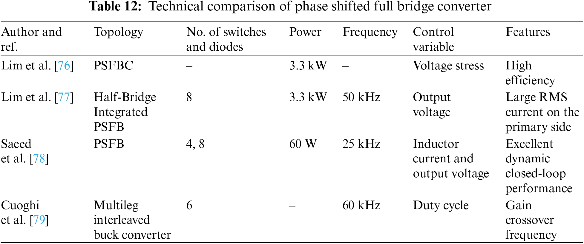
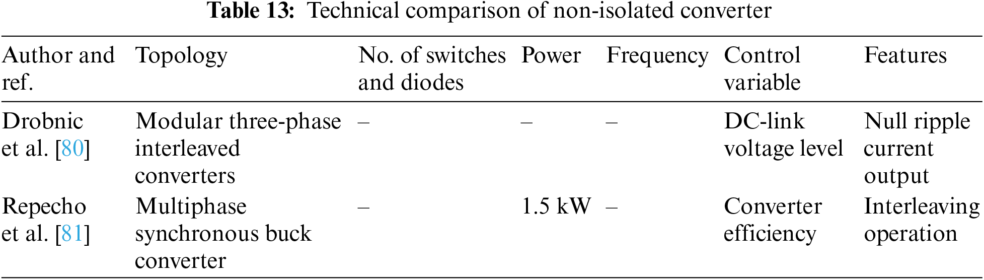
Table 13 provides a technical comparison of non-isolated converters. Reference [80] introduced a DC quick off-board battery recharge solution for EVs. In reference [81], a multiphase synchronous buck converter with innovative control strategies was designed.
Unplanned installations of fast charging stations and unregulated rapid charging can lead to significant issues [82–85]. Rapid charging consumes a large amount of power quickly, altering the load curve, which is exacerbated when multiple EVs are being charged simultaneously [86–90]. The integration of fast charging stations raises concerns related to PQ, including THD, voltage fluctuations, and supraharmonics. Fig. 10 illustrates the impact of EV charging on the power grid.
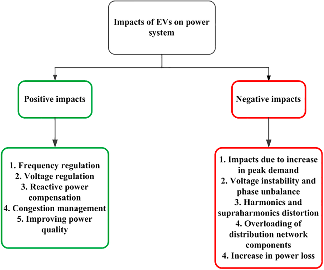
Figure 10: Impacts of EVs charging
5.1 Voltage Fluctuations, Harmonics and Supraharmonics
Usually, harmonic analysis is carried out within the frequency range below 2 kHz. However, fast charging stations may produce supra-harmonic distortions in the range of 2 to 150 kHz. Supra-harmonics can lead to issues such as excessive heating, shortened equipment lifespans, and disruptions to grid equipment, including the tripping of residual current devices. The careful selection and design of rectifiers and input filters can help eliminate THD and supraharmonics. Voltage fluctuations, another aspect of power quality, can occur when EVs are charged rapidly. According to reference [91], as the charging power increases, voltage variations on the bus also increase. Voltage variations that exceed predefined limits can result in financial penalties. In reference [92], the authors proposed a charging control strategy to mitigate power quality issues such as flicker and voltage swings. Fig. 11 illustrates the relationship between flicker severity and Fast Charging Station (FCS) penetration level.
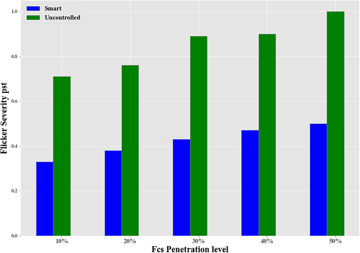
Figure 11: Flicker severity vs. FCS penetration level. Reprinted from reference [92]
As stated in article [93], the installation of EV charging stations on subpar buses can lead to various issues within the distribution network. Reference [94] explored the impact of fast charging stations on grid stability in standard benchamark system. To assess system stability, simulations of an efficient charging station were conducted [95]. Fig. 12 presents the relationship between the equivalent aging factor and the ratio of EV penetration. Several intelligent charging systems have been investigated in reference [96] to mitigate the impacts of EV.
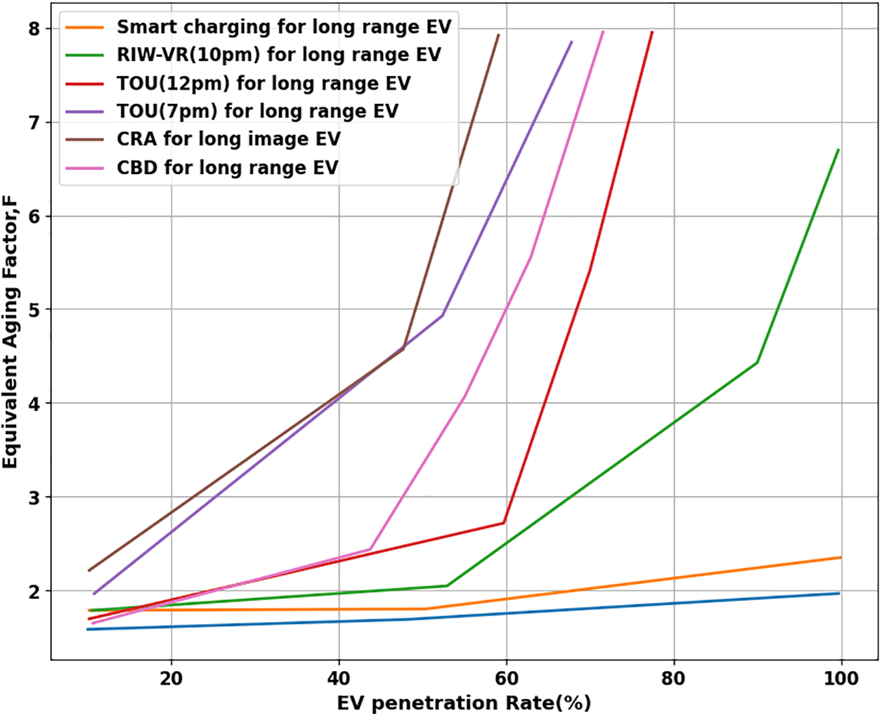
Figure 12: Equivalent aging factor vs. EV penetration ratio [95]
Fig. 13 in [97] illustrates the relationship between hot spot temperature and accelerated aging factor. The emerging technology called Vehicle-to-Grid (V2G) provides advantages such as active and reactive power, frequency and voltage regulation, peak load reduction, improved grid stability, mitigation of harmonics and supraharmonics, and support for RES. V2G technology can be instrumental in mitigating the adverse effects of fast charging [98].
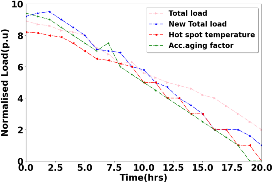
Figure 13: Hot spot temperature and accelerated aging factor. Reprinted from reference [97]
5.2 RES Powered Multi-Point EV Charging Station with Various Converter Topology
A microgrid (MG) based charging station architecture integrates various energy sources and ESUs to power distributed loads. Charging stations utilizing renewable energy sources offer the advantage of charging electric vehicles with minimal power conversion losses. These renewable energy sources may include PV panels, wind turbines, supercapacitors, and fuel cells. MGsystems face challenges related to maintaining steady-state and transient voltage and frequency control. PV systems are commonly used as the primary renewable energy source in microgrid-powered DC bus systems. These systems are configured differently to supply power to both local loads and electric vehicles. This section delves into the diverse microgrid architectures designed for EV charging, emphasizing their reliance on renewable energy sources and load connections, necessitating distinct energy management control strategies.
5.2.1 DC Microgrid with Isolation for EV Charging
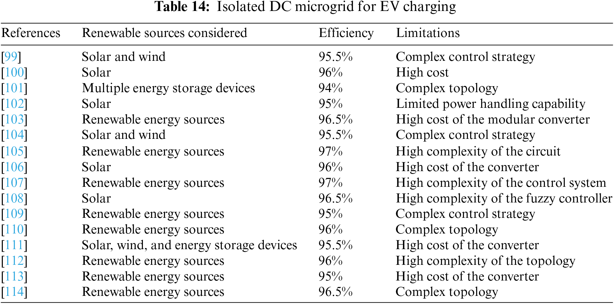
In [99], reference presents a novel interleaved Zeta–Cuk converter designed for MGand EV applications. The key outcomes include improved efficiency and reduced harmonic distortion. Limitations involve potential complexity in implementation. Applications include enhancing power conversion in microgrids and electric vehicles, contributing to greater energy efficiency and sustainability. In [100], reference investigates a PV-integrated improved quasi-Y-source DC to DC stepup converter in EV battery charging, incorporating a phase-shifted converter. Key outcomes include enhanced energy efficiency and the potential for sustainable EV charging. Limitations may involve complexity in implementation. Applications include green energy integration for efficient and eco-friendly electric vehicle charging. In [101], reference focuses on an interleaved bidirectional DC–DC converter for electric vehicle applications utilizing multiple energy storage devices. Key outcomes include improved energy management and efficient power transfer. Limitations may include increased complexity. Applications encompass electric vehicle power systems, allowing for more effective energy utilization and extended range. In [102], reference explores a PV-tied 3-port DC to DC converter in a four-wheel-drive hybrid electric vehicle (HEV). Key outcomes include enhanced power distribution and reduced reliance on the internal combustion engine. Limitations may involve system complexity. Applications encompass sustainable transportation, promoting the integration of solar power in HEVs for improved fuel efficiency and reduced emissions.
In [103], reference focuses on designing a modular converter for efficient energy management in a hybrid EV system. Key outcomes include improved charging efficiency and flexibility. Limitations may involve initial setup costs. Applications encompass enhanced infrastructure for hybrid EV charging stations, optimizing energy use and charging multiple EVs efficiently. In [104], reference presents a interleaved Zeta–Cuk converter for MG and EV applications. Key outcomes include improved efficiency and reduced harmonic distortion. Limitations may involve complex implementation. Applications encompass enhancing power conversion in microgrids and EVs, contributing to greater energy efficiency and sustainability. In [105], reference introduces a fast charging stations of EVs based on CryStAl-RDF technique. Key outcomes include enhanced charging speed and efficiency. Limitations may involve complexity in design. Applications encompass the development of high-speed EV charging infrastructure, reducing charging times and promoting widespread EV adoption. In [106], reference introduces a model predictive controlled 3-level bidirectional converter in bipolar DC MG. Key outcomes include enhanced voltage control and efficient charging. Limitations may involve the complexity of control algorithms.
Applications encompass the development of high-performance EV fast charging infrastructure within bipolar DC microgrids, ensuring reliable and efficient power supply for EVs. In [107], reference presents a modular multi-phase DC-DC converter with improved dynamic performance using Lyapunov functions. Key outcomes include enhanced converter dynamics and power transfer efficiency. Limitations may involve increased complexity. Applications include improved power management systems in various electrical applications, benefiting from enhanced converter performance and efficiency. In [108], reference evaluates the performance of a solar-combined boosting topology for EV battery charging, employing an interval type-2 fuzzy controller. Key outcomes include improved charging efficiency and reduced grid dependence. Limitations may involve the need for sophisticated control algorithms. Applications encompass sustainable and efficient EV charging solutions, integrating solar power for reduced environmental impact and cost savings. In [109], reference explores DC-DC stage of EV charging stations. Key outcomes include enhanced power conversion efficiency and charging performance. Limitations may involve design complexity. Applications encompass improved infrastructure for EV charging stations, ensuring efficient power conversion and rapid charging for EVs. In [110], reference introduces a novel cluster-switched inductor-based high step-up hybrid DC to DC converter. Key outcomes include increased voltage conversion and efficiency. Limitations may involve increased component complexity. Applications encompass advanced power conversion systems, suitable for various electrical applications where high step-up voltage conversion is required, contributing to enhanced energy efficiency.
In [111], reference presents a multi-input and multi-output bi-directional power converter for solar photovoltaic systems. Key outcomes include enhanced energy management and power distribution. Limitations may involve increased complexity in control algorithms. Applications encompass advanced energy harvesting from multiple sources in solar photovoltaic systems, improving energy utilization and efficiency. In [112], reference introduces an extended high-voltage-gain DC-DC converter with reduced voltage stress on switches/diodes. Key outcomes include increased voltage gain and reduced stress on components. Limitations may involve increased design complexity. Applications encompass efficient power conversion systems, particularly for renewable energy sources, where voltage gain and component longevity are critical factors. In [113], reference focuses on designing and implementing an Interleaved Boost Converter (IBC) to reduce voltage across the output capacitor. Key outcomes include improved voltage regulation and reduced stress on the capacitor. Limitations may involve specific operational constraints. Applications encompass enhancing power supply systems in various electrical devices, promoting better voltage control and component longevity. In [114], reference presents a modified buck converter with constant voltage stress using a CDD (Capacitor-Diode-Diode) circuit. Key outcomes include improved voltage regulation and reduced stress on components.
Limitations may involve the need for specific circuitry. Applications encompass efficient power conversion in various electrical systems, ensuring stable voltage levels and component longevity. In [115], reference optimizes isolated hybrid microgrids using different battery models and technologies in renewable energy systems. Key outcomes include improved microgrid performance and cost-effectiveness. Limitations may involve specific modeling assumptions. Applications encompass enhancing energy self-sufficiency and sustainability in isolated areas, providing reliable power using renewable sources and advanced battery technology. In [116], reference analyzes and designs a standalone EV charging station powered by PV energy. Key outcomes include sustainable and self-sufficient EV charging infrastructure. Limitations may involve intermittent charging due to weather conditions. Applications encompass eco-friendly EV charging solutions, reducing grid dependence and promoting sustainable transportation. In [117], reference outlines an optimal design of a hybrid charging station for various types of vehicles, powered by RES and battery. Key outcomes include efficient, sustainable, and flexible vehicle charging. Limitations may involve the initial setup costs. Applications encompass eco-friendly transportation infrastructure, reducing emissions and grid demand. Reference [118] centers on the economic and ecological design of hybrid RES employing hybrid algorithm.
Key outcomes include cost-effective and environmentally friendly energy systems. Limitations may involve algorithm complexity. Applications encompass sustainable power generation for various purposes, reducing costs and environmental impact. Isolated DC Microgrid for EV Charging is shown in Table 14.
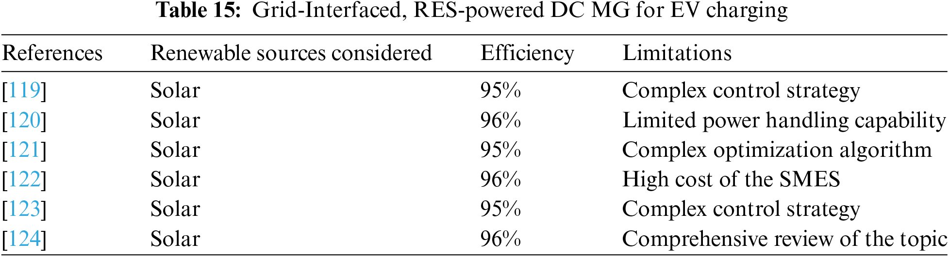
5.2.2 Grid-Interfaced, RES-Powered DC MG for EV Charging
In reference [119], a transformer-less 7-level inverter with model predictive control is presented for grid-connected PV applications. The study emphasizes efficient power conversion and grid connection, with potential limitations related to the complexity of control methods. Applications include advancing inverter technology for photovoltaic systems to enhance energy conversion and grid integration. Reference [120] focuses on managing the charging and discharging rates of EVs in a grid-connected setting to balance the grid load. Key outcomes involve optimized EV charging and grid load distribution, with potential limitations tied to the requirement for advanced load management systems. Applications encompass the development of efficient and sustainable electric vehicle charging infrastructure to alleviate grid stress. In reference [121], the study addresses the coordination of generation scheduling with PEV charging in industrial microgrids. Key outcomes include improved management of generation and PEV integration, with potential limitations associated with complex scheduling algorithms.
Applications include optimizing energy use in industrial microgrids for reliable power and cost savings. Reference [122] explores the application of small-sized Superconducting Magnetic Energy Storage (SMES) in an EV charging station with a DC bus and PV system. Key outcomes include enhanced energy storage and utilization, with potential limitations related to the cost of superconducting materials. Applications involve efficient energy storage in EV charging stations, contributing to the improvement of charging infrastructure. In reference [123], an improved control strategy for a bidirectional single-phase AC-DC converter in a hybrid AC/DC microgrid is presented. Key outcomes include optimized converter control and power transfer. Limitations may involve the complexity of control algorithms. Applications encompass advanced control systems for microgrids, ensuring efficient power conversion and grid interaction. In [124], reference focuses on electric vehicle charging using solar photovoltaic (PV) systems. Key outcomes include insights into PV-based EV charging. Limitations may involve the need for further research and development. Applications encompass the integration of solar power into EV charging infrastructure, promoting sustainable and cost-effective charging solutions. Grid-Interfaced, RES-Powered DC MG for EV Charging is shown in Table 15.
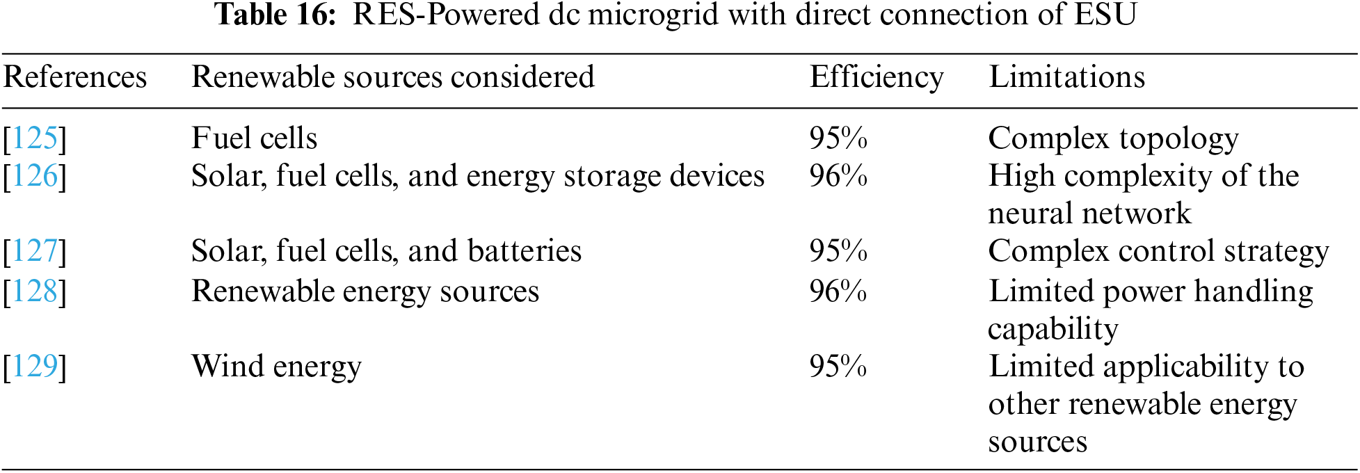
5.2.3 RES-Interfaced DC Microgrid with Direct Connection of ESU
In reference [125], a high-performance single-input three-output DC-DC high-gain converter is introduced for fuel cell-based EV. The key outcomes of this study include improved power conversion and efficiency, with potential limitations related to the complexity of design. Applications involve enhanced energy management for fuel cell-based EVs, contributing to better overall performance and sustainability. Reference [126] focuses on the design of a neural network-based energy management system for a HEV with inputs from solar PV, fuel cells, batteries, and ultracapacitors. The key outcomes of this study include optimized energy utilization and efficient power distribution. Potential limitations may arise from the complexity of neural network modeling. Applications encompass advanced energy management for HEV, aiming to enhance sustainability and efficiency in transportation. In reference [127], the study addresses the mitigation of circulating current through effective energy management in a low-power PV-FC-battery microgrid. The key outcomes involve improved energy flow control and efficient power distribution, with potential limitations related to complex control algorithms.
Applications include enhanced energy management in microgrid systems to ensure stable power supply and grid interaction. Narasipuram et al. [128] focuses on the optimal charging of PEVs in a car-park infrastructure. Key outcomes include efficient EV charging and grid interaction, with potential limitations associated with the need for advanced charging infrastructure. Applications encompass optimized charging solutions for electric vehicles, aiming to reduce grid stress and enhance the adoption of electric vehicles. In reference [129], a simple wind energy controller for an expanded operating range is presented. Key outcomes include improved wind energy utilization and control. Limitations may involve specific operational constraints. Applications include enhanced wind energy systems, ensuring efficient power conversion and utilization. RES-Powered DC Microgrid with Direct Connection of ESUis shown in Table 16.
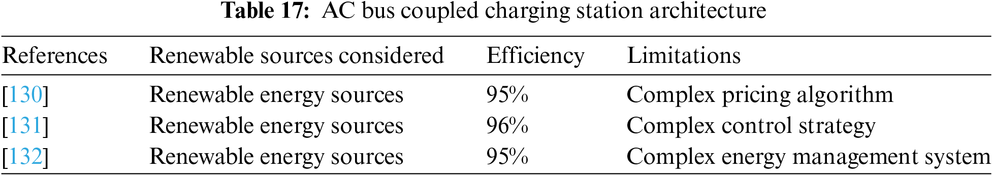
5.2.4 AC Bus Coupled Charging Station Architecture
In [130], reference proposes stochastic dynamic pricing for EV charging stations with renewable integration and energy storage. Key outcomes include optimized pricing strategies for EV charging, integrating renewables, and energy storage. Limitations may involve complex pricing algorithms. Applications encompass efficient and sustainable EV charging infrastructure, promoting renewable energy integration. In [131], reference presents a control algorithm for electric vehicle fast charging stations equipped with flywheel energy storage systems. Key outcomes include improved control and energy management for fast charging stations. Limitations may involve specific energy storage requirements. Applications include advanced energy management for fast EV charging, enhancing charging station efficiency. In [132], reference introduces an intelligent hybrid energy management system for a smart house, considering bidirectional power flow and various EV charging techniques. Key outcomes include efficient power management for smart homes and EVs. Limitations may involve the complexity of managing bidirectional power flow. Applications encompass smart home energy systems, ensuring efficient power distribution and EV charging. AC Bus Coupled Charging Station Architecture is shown in Table 17.
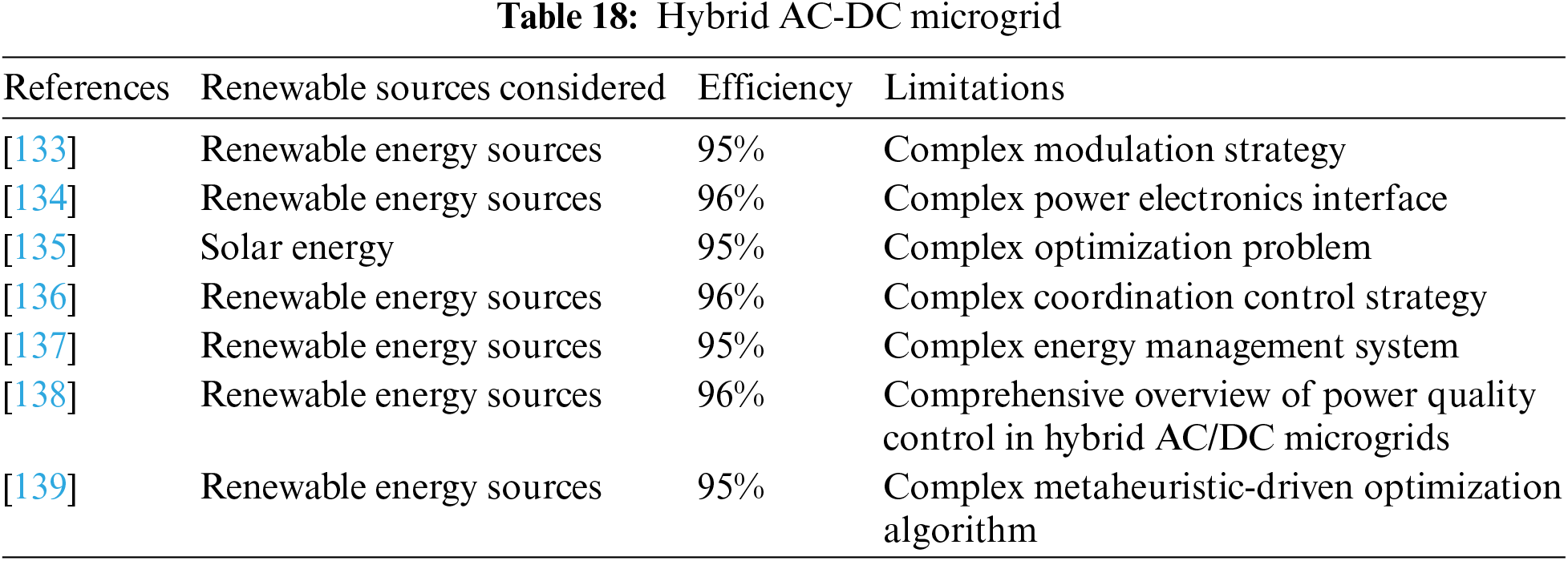
In [133], reference focuses on improving hybrid current modulation for bidirectional power flow in a single-stage dual active bridge AC/DC converter. Key outcomes include enhanced bidirectional power control and efficiency. Limitations may involve complex modulation techniques. Applications encompass efficient bidirectional power flow in various electronic systems. In [134], reference integrates inductively coupled power transfer and a hybrid energy storage system for battery-powered electric vehicles. Key outcomes include improved power interface and energy storage. Limitations may involve specific hardware requirements. Applications include efficient energy storage and charging solutions for electric vehicles. In [135], reference focuses on the temporal matching of solar PV and EV charging at a city scale. Key outcomes include optimized utilization of solar energy and EV charging coordination. Limitations may involve complex scheduling algorithms.
Applications encompass sustainable and efficient energy management for urban areas. In [136], reference presents a hybrid AC/DC microgrid and its coordination control. Key outcomes include improved microgrid control and coordination. Limitations may involve specific control strategies. Applications include enhanced control of AC/DC microgrids for efficient power distribution. In [137], reference addresses energy management for a residential microgrid using wavelet transform and fuzzy control, including a vehicle-to-grid system. Key outcomes include efficient energy management and integration of electric vehicle systems. Limitations may involve the complexity of control algorithms. Applications encompass smart residential microgrid energy management. In [138], reference provides an overview of power quality control in smart hybrid AC/DC microgrids. Key outcomes include improved power quality control strategies. Limitations may involve the need for advanced control algorithms. Applications include enhanced power quality in hybrid microgrid systems. In [139], reference focuses on hybrid microgrid energy management and control, considering intermittent renewable sources and electric vehicle charging. Key outcomes include efficient energy management in hybrid microgrids. Limitations may involve complex control algorithms. Applications encompass sustainable and efficient energy management in hybrid microgrid systems. Hybrid AC-DC Microgrid is shown in Table 18.
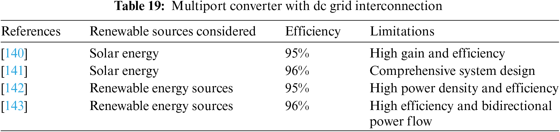
5.2.6 Multiport Converter with DC Grid Interconnection
In [140], reference presents transformerless high gain boost and buck-boost DC-DC converters for standalone photovoltaic systems. Key outcomes include efficient power conversion with extendable switched capacitor (SC) cells. Limitations may involve complex control strategies. Applications include enhanced power conversion in solar energy systems. In [141], reference focuses on system design for a solar-powered electric vehicle charging station at workplaces. Key outcomes include sustainable workplace charging solutions. Limitations may involve site-specific considerations. Applications encompass efficient and eco-friendly electric vehicle charging infrastructure. In [142], reference addresses the modeling and control of a multiport Power Electronic Transformer (PET) for electric traction applications. Key outcomes include efficient power transformation and control strategies. Limitations may involve specific control challenges. Applications include improved power electronics in electric traction systems. In [143], reference presents a modified topology for a bidirectional DC-DC converter with synchronous rectification. Key outcomes include enhanced bidirectional power flow with synchronous rectification. Limitations may involve specific hardware requirements. Applications include efficient energy storage and power conversion in various systems. Multiport Converter with DC Grid Interconnection is shown in Table 19.
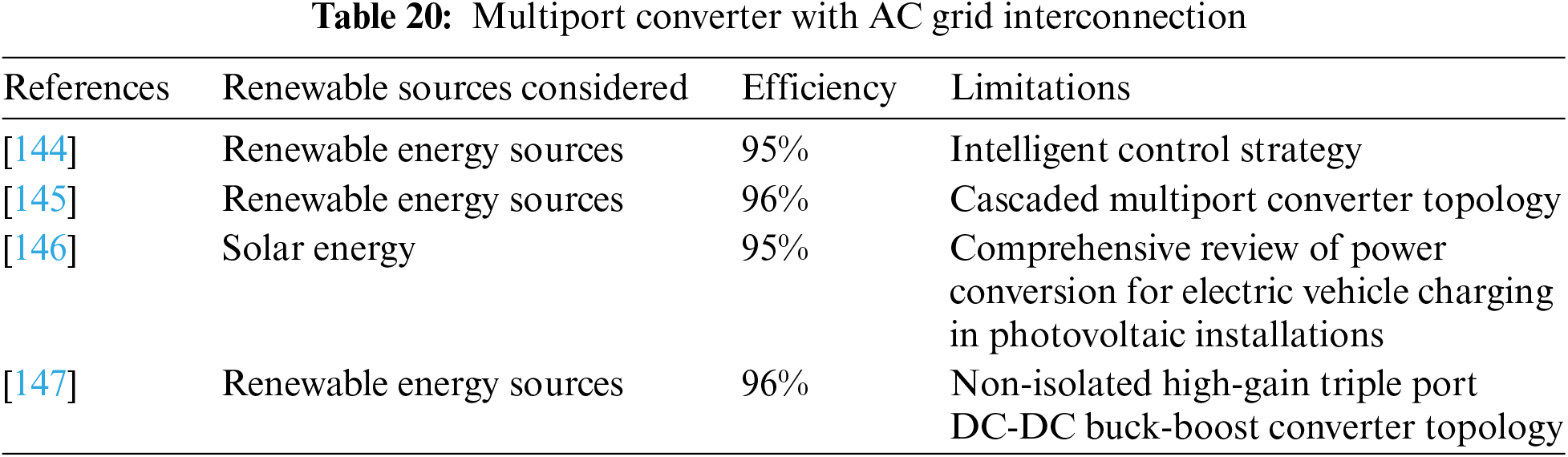
5.2.7 Multiport Converter with AC Grid Interconnection Grid
In [144], reference explores intelligent control of converters for electric vehicle charging stations. Key outcomes include enhanced converter control strategies for efficient charging. Limitations may involve complex control algorithms. Applications encompass intelligent and efficient electric vehicle charging infrastructure. In [145], reference presents a cascaded multiport converter for switched reluctance motor (SRM)-based hybrid electrical vehicle applications. Key outcomes include improved power conversion for SRM-based systems. Limitations may involve specific hardware requirements. Applications include efficient power conversion in hybrid electrical vehicles.
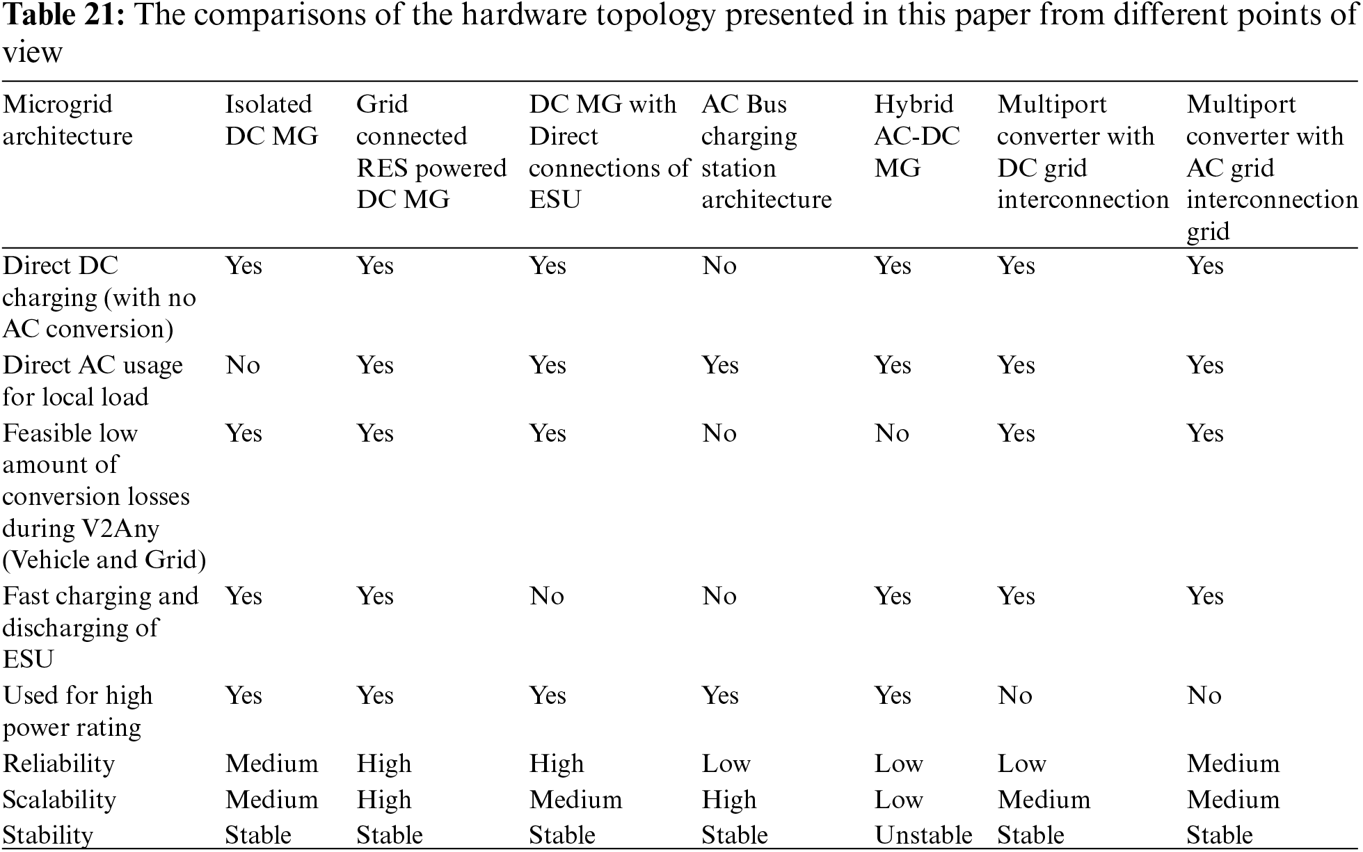
In [146], reference discusses technical considerations for power conversion in photovoltaic-based electric and plug-in hybrid electric vehicle battery charging installations. Key outcomes include efficient power conversion strategies. Limitations may involve site-specific requirements. Applications encompass photovoltaic-based battery charging solutions. In [147], reference presents a non-isolated high-gain triple port DC-DC buck-boost converter for photovoltaic applications. Key outcomes include efficient power conversion with positive output voltage. Limitations may involve specific hardware and voltage requirements. Applications include enhanced power conversion in photovoltaic systems. Multiport Converter with AC Grid Interconnection is shown in Table 20. The comparisons of the hardware topology presented in this paper from different points of view are shown in Table 21.
5.2.8 Current Issues in EV Charging
Current issues in EV charging present significant challenges for drivers and the overall adoption of electric vehicles. One major concern is reliability and maintenance, as many EV drivers encounter broken or malfunctioning chargers; a study indicates that charging stations in the U.S. have an average reliability score of only 78%, meaning about one in five chargers are non-functional. Additionally, there are infrastructure gaps, particularly in rural areas, where “charging deserts” exist and public chargers are scarce. Pricing and payment methods also pose challenges, as the cost of charging can be erratic and non-transparent, complicating the integration of various payment options. Furthermore, interoperability issues arise when different EVs and chargers are incompatible, leading to user inconvenience. Lastly, accessibility remains a critical concern, as many charging stations are not designed with individuals with disabilities in mind, making it difficult for them to use these facilities. Addressing these issues is essential for enhancing the EV charging experience and promoting wider adoption of electric vehicles.
5.2.9 Future Trends in EV Charging
Future trends in EV charging indicate a promising evolution in infrastructure and technology aimed at enhancing user experience. One significant trend is the expansion of public charging infrastructure, with a notable increase in charging points, particularly in urban areas where home charging is less feasible. Additionally, there will be a greater emphasis on developing fast charging networks along highways to facilitate long-distance travel. The rise of smart charging solutions is also noteworthy, as these technologies optimize charging times and costs for users. Furthermore, Vehicle-to-Grid (V2G) technology is gaining traction, allowing EVs to feed electricity back into the grid, which helps balance supply and demand. The introduction of Plug and Charge standards will simplify the charging process by enabling automatic authentication and charging initiation when an EV is plugged in. Lastly, new business models, such as subscription-based charging services and EV roaming agreements, are emerging to make charging more convenient and cost-effective. Collectively, these trends reflect ongoing efforts to address current challenges in EV charging and improve the overall user experience.
This study provides a thorough examination of various power electronic device topologies and their control systems in electric vehicles (EVs). It explores several key areas, including an in-depth analysis of fast charging architectures that involve rectifiers and converters. The evaluation emphasizes the functions of these converters, such as regulating battery voltage, coordinating between vehicles and the grid, and minimizing output ripple.
Furthermore, the study addresses the impact of constructing fast charging stations on the grid, highlighting the need for careful planning, management, and oversight. A comparative analysis of different converter topologies is conducted, evaluating their advantages, disadvantages, and performance metrics such as power and frequency.
The study also discusses common control objectives for rectifiers, including minimizing total harmonic distortion (THD), achieving a high power factor, and maintaining stable DC link voltage. Ultimately, it underscores the significance of advanced control algorithms, reliability, cost-effectiveness, and efficiency, emphasizing the vital role of power electronic converters in promoting the widespread adoption of electric vehicles.
Acknowledgement: The first and fourth authors are affiliated with Cyient Ltd., and Eaton India Innovation Center LLP, respectively. The views expressed in this paper are those of the authors and does not represents the view of his employers.
Funding Statement: The authors received no specific funding for this study.
Author Contributions: The authors confirm contribution to the paper as follows: Rajanand Patnaik Narasipuram: Conceptualization, Methodology, Formal analysis, Investigation, Supervision, Writing—original draft; Md M. Pasha: Data collection, Modifications, Writing—review & editing, Supervision; Saleha Tabassum: Modifications, Writing—review & editing, Visualization; Amit Singh Tandon: Writing—review & editing, Visualization. All authors reviewed the results and approved the final version of the manuscript.
Availability of Data and Materials: Not applicable.
Ethics Approval: Not applicable.
Conflicts of Interest: The authors declare no conflicts of interest to report regarding the present study.
References
1. Y. Yilmaz and P. T. Krein, “Review of battery charger topologies, charging power levels, and infrastructure for plug-in electric and hybrid vehicles,” IEEE Trans. Power Electron, vol. 28, no. 4, pp. 2151–2169, 2013. doi: 10.1109/TPEL.2012.2212917. [Google Scholar] [CrossRef]
2. A. König, L. Nicoletti, D. Schröder, S. Wolff, A. Waclaw and M. Lienkamp, “An overview of parameter and cost for battery electric vehicles,” World Electr. Veh. J., vol. 12, no. 1, 2021, Art. no. 21. doi: 10.3390/wevj12010021. [Google Scholar] [CrossRef]
3. M. Adhikari, L. P. Ghimire, Y. Kim, P. Aryal, and S. B. Khadka, “Identification and analysis of barriers against electric vehicle use,” Sustainability, vol. 12, no. 12, 2020, Art. no. 4850. doi: 10.3390/su12124850. [Google Scholar] [CrossRef]
4. G. Krishna, “Understanding and identifying barriers to electric vehicle adoption through thematic analysis,” Transp Res. Interdiscip. Perspect., vol. 10, 2021, Art. no. 100364. doi: 10.1016/j.trip.2021.100364. [Google Scholar] [CrossRef]
5. N. Rigogiannis, I. Bogatsis, C. Pechlivanis, A. Kyritsis, and N. Papanikolaou, “Moving towards greener road transportation: A review,” Clean Technol., vol. 5, no. 2, pp. 766–790, 2023. doi: 10.3390/cleantechnol5020038. [Google Scholar] [CrossRef]
6. B. Singh, B. N. Singh, A. Chandra, K. Al-Haddad, A. Pandey and D. P. Kothari, “A review of three-phase improved power quality AC-DC converters,” IEEE Trans. Ind. Electron., vol. 51, no. 4, pp. 641–660, 2004. doi: 10.1109/TIE.2004.825341. [Google Scholar] [CrossRef]
7. R. P. Narasipuram and S. Mopidevi, “A dual primary side FB DC-DC converter with variable frequency phase shift control strategy for on/off board EV charging applications,” in Proc. 2023 9th IEEE India Int. Conf. Power Electron. (IICPE), Sonipat, India, 2023, pp. 1–5. doi: 10.1109/IICPE60303.2023.10474754. [Google Scholar] [CrossRef]
8. S. Srdic and S. Lukic, “Toward extreme fast charging: Challenges and opportunities in directly connecting to medium-voltage line,” IEEE Electr. Mag., vol. 7, no. 3, pp. 22–31, 2019. doi: 10.1109/MELE.2018.2889547. [Google Scholar] [CrossRef]
9. R. P. Narasipuram, V. A. Karkhanis, M. Ellinger, K. M. Saranath, G. Alagarsamy and R. Jadhav, “Systems engineering—A key approach to transportation electrification,” in Symp. Int. Autom. Technol., Warrendale, PA, USA, SAE International, 2024. doi: 10.4271/2024-26-0128. [Google Scholar] [CrossRef]
10. M. Safayatullah, M. T. Elrais, S. Ghosh, R. Rezaii, and I. Batarseh, “A comprehensive review of power converter topologies and control methods for electric vehicle fast charging applications,” IEEE Access, vol. 10, pp. 40753–40793, 2022. doi: 10.1109/ACCESS.2022.3166935. [Google Scholar] [CrossRef]
11. I. Rahman, P. M. Vasant, B. S. M. Singh, M. Abdullah-Al-Wadud, and N. Adnan, “Review of recent trends in optimization techniques for plug-in hybrid, and electric vehicle charging infrastructures,” Renew Sustainable Energy Rev., vol. 58, pp. 1039–1047, 2016. doi: 10.1016/j.rser.2015.12.353. [Google Scholar] [CrossRef]
12. T. Chen et al., “A review on electric vehicle charging infrastructure development in the UK,” J. Mod. Power Syst. Clean Energy, vol. 8, no. 1, pp. 193–205, 2020. doi: 10.35833/MPCE.2018.000374. [Google Scholar] [CrossRef]
13. A. Ahmad, Z. A. Khan, M. Saad Alam, and S. Khateeb, “A review of the electric vehicle charging techniques, standards, progression and evolution of EV technologies in Germany,” Smart Sci., vol. 6, no. 1, pp. 36–53, 2017. doi: 10.1080/23080477.2017.1420132. [Google Scholar] [CrossRef]
14. V. Krithika and C. Subramani, “A comprehensive review on choice of hybrid vehicles and power converters, control strategies for hybrid electric vehicles,” Int. J. Energy Res, vol. 42, no. 15, pp. 1789–1812, 2017. doi: 10.1002/er.3952. [Google Scholar] [CrossRef]
15. A. Khaligh and M. D’Antonio, “Global trends in high-power on-board chargers for electric vehicles,” IEEE Trans. Veh. Technol., vol. 68, no. 4, pp. 3306–3324, 2019. doi: 10.1109/TVT.2019.2897050. [Google Scholar] [CrossRef]
16. I. Subotic, N. Bodo, E. Levi, B. Dumnic, D. Milicevic and V. Katic, “Overview of fast on-board integrated battery chargers for electric vehicles based on multiphase machines and power electronics,” IET Electr. Power Appl., vol. 10, no. 3, pp. 217–229, 2016. doi: 10.1049/IET-EPA.2015.0292. [Google Scholar] [CrossRef]
17. R. P. Narasipuram and S. Mopidevi, “Parametric modelling of interleaved resonant DC-DC converter with common secondary rectifier circuit for xEV charging applications,” in Proc. 2023 Int. Conf. Sustainable Emerg. Innov. Eng. Technol. (ICSEIET), Ghaziabad, India, 2023, pp. 842–846. doi: 10.1109/ICSEIET58677.2023.10303318. [Google Scholar] [CrossRef]
18. S. Chakraborty, H. -N. Vu, M. M. Hasan, D. -D. Tran, M. E. Baghdadi and O. Hegazy, “DC-DC converter topologies for electric vehicles, plug-in hybrid electric vehicles and fast charging stations: State of the art and future trends,” Energies, vol. 12, no. 8, 2019, Art. no. 1569. doi: 10.3390/en12081569. [Google Scholar] [CrossRef]
19. H. Tu, H. Feng, S. Srdic, and S. Lukic, “Extreme fast charging of electric vehicles: A technology overview,” IEEE Trans. Transp. Electr., vol. 5, no. 3, pp. 861–878, 2019. doi: 10.1109/TTE.2019.2958709. [Google Scholar] [CrossRef]
20. K. Dimitriadou, N. Rigogiannis, S. Fountoukidis, F. Kotarela, A. Kyritsis and N. Papanikolaou, “Current trends in electric vehicle charging infrastructure; Opportunities and challenges in wireless charging integration,” Energies, vol. 16, no. 4, 2023, Art. no. 2057. doi: 10.3390/en16042057. [Google Scholar] [CrossRef]
21. S. Eaves and J. Eaves, “A cost comparison of fuel-cell and battery electric vehicles,” J. Power Sources, vol. 130, pp. 208–212, 2004. doi: 10.1016/j.jpowsour.2003.12.016. [Google Scholar] [CrossRef]
22. J. de Santiago et al., “Electrical motor drivelines in commercial all-electric vehicles: A review,” IEEE Trans. Veh. Technol., vol. 61, no. 1, pp. 475–484, 2012. doi: 10.1109/TVT.2011.2177873. [Google Scholar] [CrossRef]
23. J. Jui, A. A. Mohd, M. M. M. Imran, and I. M. R. Muhammad, “Optimal energy management strategies for hybrid electric vehicles: A recent survey of machine learning approaches,” J. Eng. Res., vol. 12, no. 3, pp. 454–467, 2024. doi: 10.1016/j.jer.2024.01.016. [Google Scholar] [CrossRef]
24. H. He, R. Xiong, H. Guo, and S. Li, “Comparison study on the battery models used for the energy management of batteries in electric vehicles,” Energy Convers. Manage., vol. 64, pp. 113–121, 2012. doi: 10.1016/j.enconman.2012.04.014. [Google Scholar] [CrossRef]
25. M. Adil, J. Ali, Q. T. Ta, M. Attique, and T. -S. Chung, “A reliable sensor network infrastructure for electric vehicles to enable dynamic wireless charging based on machine learning technique,” IEEE Access, vol. 8, pp. 187933–187947, 2020. doi: 10.1109/ACCESS.2020.3031182. [Google Scholar] [CrossRef]
26. D. Wang, X. Qu, Y. Yao, and P. Yang, “Hybrid inductive-power-transfer battery chargers for electric vehicle onboard charging with configurable charging profile,” IEEE Trans. Intell. Transp. Syst., vol. 22, no. 1, pp. 592–599, 2021. doi: 10.1109/TITS.2020.2976647. [Google Scholar] [CrossRef]
27. J. Wang et al., “Nonisolated electric vehicle chargers: Their current status and future challenges,” IEEE Electr. Mag., vol. 9, no. 3, pp. 23–33, 2021. doi: 10.1109/MELE.2021.3070935. [Google Scholar] [CrossRef]
28. Y. Tahir et al., “A state-of-the-art review on topologies and control techniques of solid-state transformers for electric vehicle extreme fast charging,” IET Power Electr., vol. 14, no. 8, pp. 1560–1576, 2021. doi: 10.1049/pel2.12141. [Google Scholar] [CrossRef]
29. R. Greul, S. D. Round, and J. W. Kolar, “Analysis and control of a three-phase, unity power factor $y$-rectifier,” IEEE Trans. Power Electr., vol. 22, no. 5, pp. 1900–1911, 2007. doi: 10.1109/TPEL.2007.904187. [Google Scholar] [CrossRef]
30. T. B. Soeiro and J. W. Kolar, “Analysis of high-efficiency three-phase two- and three-level unidirectional hybrid rectifiers,” IEEE Trans. Ind. Electron., vol. 60, no. 9, pp. 3589–3601, 2013. doi: 10.1109/TIE.2012.2205358. [Google Scholar] [CrossRef]
31. J. W. Kolar and T. Friedli, “The essence of three-phase PFC rectifier systems—Part I,” IEEE Trans. Power Electr., vol. 28, no. 6, pp. 176–198, 2013. doi: 10.1109/TPEL.2012.2197867. [Google Scholar] [CrossRef]
32. J. Lei, S. Feng, J. Zhao, W. Chen, P. Wheeler and M. Shi, “An improved three-phase buck rectifier topology with reduced voltage stress on transistors,” IEEE Trans. Power Electr., vol. 35, no. 12, pp. 2458–2466, 2020. doi: 10.1109/TPEL.2019.2931803. [Google Scholar] [CrossRef]
33. Q. Chen, J. Xu, F. Zeng, R. Huang, and L. Wang, “An improved three-phase buck rectifier with low voltage stress on switching devices,” IEEE Trans. Power Electr., vol. 36, no. 23, pp. 6168–6174, 2021. doi: 10.1109/TPEL.2020.3035030. [Google Scholar] [CrossRef]
34. Q. Chen, J. Xu, R. Huang, W. Wang, and L. Wang, “A digital control strategy with simple transfer matrix for three-phase buck rectifier under unbalanced AC input conditions,” IEEE Trans. Power Electr., vol. 36, no. 14, pp. 3661–3666, 2021. doi: 10.1109/TPEL.2020.3019291. [Google Scholar] [CrossRef]
35. Q. Chen, J. Xu, L. Wang, R. Huang, and H. Ma, “Analysis and improvement of the effect of distributed parasitic capacitance on high-frequency high-density three-phase buck rectifier,” IEEE Trans. Power Electr., vol. 36, no. 18, pp. 6415–6428, 2021. doi: 10.1109/TPEL.2020.3035264. [Google Scholar] [CrossRef]
36. A. K. Singh, E. Jeyasankar, P. Das, and S. K. Panda, “A matrix-based nonisolated three-phase AC-DC rectifier with large step-down voltage gain,” IEEE Trans. Power Electr., vol. 32, no. 6, pp. 4796–4811, 2017. doi: 10.1109/TPEL.2016.2596842. [Google Scholar] [CrossRef]
37. J. Afsharian, D. Xu, B. Wu, B. Gong, and Z. Yang, “A new PWM and commutation scheme for one-phase loss operation of three-phase isolated buck matrix-type rectifier,” IEEE Trans. Power Electr., vol. 33, no. 12, pp. 9854–9865, 2018. doi: 10.1109/TPEL.2018.2789905. [Google Scholar] [CrossRef]
38. G. Rajendran, C. A. Vaithilingam, N. Misron, K. Naidu, and M. R. Ahmed, “Voltage oriented controller based Vienna rectifier for electric vehicle charging stations,” IEEE Access, vol. 9, pp. 50798–50809, 2021. doi: 10.1109/ACCESS.2021.3068653. [Google Scholar] [CrossRef]
39. L. Schrittwieser, M. Leibl, M. Haider, F. Thony, J. W. Kolar and T. B. Soeiro, “99.3% efficient three-phase buck-type all-SiC Swiss rectifier for DC distribution systems,” IEEE Trans. Power Electr., vol. 34, no. 1, pp. 126–140, 2019. doi: 10.1109/TPEL.2018.2826536. [Google Scholar] [CrossRef]
40. B. Zhang, S. Xie, X. Wang, and J. Xu, “Modulation method and control strategy for full-bridge-based Swiss rectifier to achieve ZVS operation and suppress low-order harmonics of injected current,” IEEE Trans. Power Electr., vol. 35, no. 6, pp. 6512–6522, 2020. doi: 10.1109/TPEL.2019.2947186. [Google Scholar] [CrossRef]
41. L. Schrittwieser, J. W. Kolar, and T. B. Soeiro, “Novel Swiss rectifier modulation scheme preventing input current distortions at sector boundaries,” IEEE Trans. Power Electr., vol. 32, no. 8, pp. 5771–5785, 2017. doi: 10.1109/TPEL.2016.2616403. [Google Scholar] [CrossRef]
42. L. Zhang et al., “A modified DPWM with neutral point voltage balance capability for three-phase Vienna rectifiers,” IEEE Trans. Power Electr., vol. 36, no. 2, pp. 263–273, 2021. doi: 10.1109/TPEL.2020.3006145. [Google Scholar] [CrossRef]
43. Q. Wang, X. Zhang, R. Burgos, D. Boroyevich, A. M. White and M. Kheraluwala, “Design and implementation of a two-channel interleaved Vienna-type rectifier with >99% efficiency,” IEEE Trans. Power Electr., vol. 33, no. 5, pp. 226–239, 2018. doi: 10.1109/TPEL.2017.2707341. [Google Scholar] [CrossRef]
44. T. Wang, C. Chen, P. Liu, T. Liu, Z. Chao and S. Duan, “A hybrid space-vector modulation method for harmonics and current ripple reduction of interleaved Vienna rectifier,” IEEE Trans. Ind. Electron., vol. 67, no. 9, pp. 8088–8099, 2020. doi: 10.1109/TIE.2019.2947810. [Google Scholar] [CrossRef]
45. L. Huber, M. Kumar, and M. Jovanovic, “Performance comparison of three-step and six-step PWM in average-current-controlled three-phase six-switch boost PFC rectifier,” IEEE Trans. Power Electr., vol. 30, no. 2, p. 1, 2015. doi: 10.1109/TPEL.2014.2305071. [Google Scholar] [CrossRef]
46. A. Mallik, W. Ding, C. Shi, and A. Khaligh, “Input voltage sensorless duty compensation control for a three-phase boost PFC converter,” IEEE Trans. Ind. Appl., vol. 53, pp. 1527–1537, 2017. doi: 10.1109/TIA.2016.2626247. [Google Scholar] [CrossRef]
47. L. Huber, M. Kumar, and M. M. Jovanovic, “Performance comparison of PI and P compensation in DSP-based average-current-controlled three-phase six-switch boost PFC rectifier,” IEEE Trans. Power Electr., vol. 30, pp. 7123–7137, 2015. doi: 10.1109/TPEL.2015.2389654. [Google Scholar] [CrossRef]
48. Y. Deng, Y. Wang, K. H. Teo, and R. G. Harley, “A simplified space vector modulation scheme for multilevel converters,” IEEE Trans. Power Electr., vol. 31, pp. 1873–1886, 2016. doi: 10.1109/TPEL.2015.2429595. [Google Scholar] [CrossRef]
49. A. Dekka, B. Wu, and N. R. Zargari, “Start-up operation of a modular multilevel converter with flying capacitor submodules,” IEEE Trans. Power Electr., vol. 32, pp. 5873–5877, 2017. doi: 10.1109/TPEL.2016.2613519. [Google Scholar] [CrossRef]
50. D. Sha, G. Xu, and Y. Xu, “Utility direct interfaced charger/discharger employing unified voltage balance control for cascaded H-bridge units and decentralized control for CF-DAB modules,” IEEE Trans. Ind. Electron., vol. 64, pp. 7831–7841, 2017. doi: 10.1109/TIE.2017.2682759. [Google Scholar] [CrossRef]
51. J. Azurza Anderson, G. Zulauf, P. Papamanolis, S. Hobi, S. Miric and J. W. Kolar, “Three levels are not enough: Scaling laws for multilevel converters in AC/DC applications,” IEEE Trans. Power Electr., vol. 36, pp. 3967–3986, 2021. doi: 10.1109/TPEL.2020.3025898. [Google Scholar] [CrossRef]
52. Y. Lei et al., “A 2-kW single-phase seven-level flying capacitor multilevel inverter with an active energy buffer,” IEEE Trans. Power Electr., vol. 32, pp. 8570–8581, 2017. doi: 10.1109/TPEL.2017.2650140. [Google Scholar] [CrossRef]
53. S. Qin, Y. Lei, Z. Ye, D. Chou, and R. C. Pilawa-Podgurski, “A high-power-density power factor correction front end based on seven-level flying capacitor multilevel converter,” IEEE J. Emerg. Sel. Topics Power Electron, vol. 7, pp. 1883–1898, 2019. doi: 10.1109/JESTPE.2019.2893264. [Google Scholar] [CrossRef]
54. S. Rivera, B. Wu, S. Kouro, V. Yaramasu, and J. Wang, “Electric vehicle charging station using a neutral point clamped converter with bipolar DC bus,” IEEE Trans. Ind. Electron., vol. 62, pp. 1999–2009, 2015. doi: 10.1109/TIE.2014.2354405. [Google Scholar] [CrossRef]
55. L. Tan, B. Wu, V. Yaramasu, S. Rivera, and X. Guo, “Effective voltage balance control for bipolar-DC-bus-fed EV charging station with three-level DC-DC fast charger,” IEEE Trans. Ind. Electron., vol. 63, pp. 4031–4041, 2016. doi: 10.1109/TIE.2016.2525987. [Google Scholar] [CrossRef]
56. F. E. Reis, R. P. Torrico-Bascope, F. L. Tofoli, and L. D. Santos Bezerra, “Bidirectional three-level stacked neutral-point-clamped converter for electric vehicle charging stations,” IEEE Access, vol. 8, pp. 37565–37577, 2020. doi: 10.1109/ACCESS.2020.2976003. [Google Scholar] [CrossRef]
57. M. Abarzadeh, W. A. Khan, N. Weise, K. Al-Haddad, and A. M. El-Refaie, “A new configuration of paralleled modular ANPC multilevel converter controlled by an improved modulation method for 1 MHz, 1 MW EV charger,” IEEE Trans. Ind. Appl., vol. 57, pp. 3164–3178, 2021. doi: 10.1109/TIA.2021.3081946. [Google Scholar] [CrossRef]
58. H. Haga and F. Kurokawa, “Modulation method of a full-bridge three-level LLC resonant converter for battery charger of electrical vehicles,” IEEE Trans. Power Electr., vol. 32, pp. 2498–2507, 2017. doi: 10.1109/TPEL.2016.2565542. [Google Scholar] [CrossRef]
59. R. P. Narasipuram and S. Mopidevi, “A novel hybrid control strategy and dynamic performance enhancement of a 3.3 kW GaN-HEMT-based iL2C resonant full-bridge DC-DC power converter methodology for electric vehicle charging systems,” Energies, vol. 16, no. 15, 2023, Art. no. 5811. doi: 10.3390/en16155811. [Google Scholar] [CrossRef]
60. L. A. Ta, N. D. Dao, and D. C. Lee, “High-efficiency hybrid LLC resonant converter for on-board chargers of plug-in electric vehicles,” IEEE Trans. Power Electr., vol. 35, pp. 8324–8334, 2020. doi: 10.1109/TPEL.2020.2971582. [Google Scholar] [CrossRef]
61. Z. U. Zahid, Z. M. Dalala, R. Chen, B. Chen, and J. -S. Lai, “Design of bidirectional DC-DC resonant converter for vehicle-to-grid (V2G) applications,” IEEE Trans. Transport Electr., vol. 1, pp. 232–244, 2015. doi: 10.1109/TTE.2015.2470056. [Google Scholar] [CrossRef]
62. H. Li, Z. Zhang, S. Wang, J. Tang, X. Ren and Q. Chen, “A 300-KHz 6.6-kW SiC bidirectional LLC onboard charger,” IEEE Trans. Ind. Electr., vol. 67, pp. 1435–1445, 2020. doi: 10.1109/TIE.2019.2901450. [Google Scholar] [CrossRef]
63. Y. Yan, H. Bai, A. Foote, and W. Wang, “Securing full-power-range zero-voltage switching in both steady-state and transient operations for a dual-active-bridge-based bidirectional electric vehicle charger,” IEEE Trans. Power Electr., vol. 35, pp. 7506–7519, 2020. doi: 10.1109/TPEL.2019.2958763. [Google Scholar] [CrossRef]
64. S. A. Assadi, H. Matsumoto, M. Moshirvaziri, M. Nasr, M. S. Zaman and O. Trescases, “Active saturation mitigation in high-density dual-active-bridge DC-DC converter for on-board EV charger applications,” IEEE Trans. Power Electr., vol. 35, pp. 4376–4387, 2020. doi: 10.1109/TPEL.2019.2939301. [Google Scholar] [CrossRef]
65. Y. Xuan, X. Yang, W. Chen, T. Liu, and X. Hao, “A three-level dual-active-bridge converter with blocking capacitors for bidirectional electric vehicle charger,” IEEE Access, vol. 7, pp. 173838–173847, 2019. doi: 10.1109/ACCESS.2019.2956834. [Google Scholar] [CrossRef]
66. D. -D. Nguyen, N. -T. Bui, and K. Yukita, “Design and optimization of three-phase dual-active-bridge converters for electric vehicle charging stations,” Energies, vol. 13, 2019, Art. no. 150. doi: 10.3390/en13010150. [Google Scholar] [CrossRef]
67. K. Shi, D. Zhang, Z. Zhou, M. Zhang, and Y. Gu, “A novel phase-shift dual full-bridge converter with full soft-switching range and wide conversion range,” IEEE Trans. Power Electr., vol. 31, pp. 7747–7760, 2016. doi: 10.1109/TPEL.2015.2512848. [Google Scholar] [CrossRef]
68. Y. Shi, R. Li, Y. Xue, and H. Li, “Optimized operation of current-fed dual active bridge DC-DC converter for PV applications,” IEEE Trans. Ind. Electr., vol. 62, pp. 6986–6995, 2015. doi: 10.1109/TIE.2015.2435000. [Google Scholar] [CrossRef]
69. D. Sha, F. You, and X. Wang, “A high-efficiency current-fed semi-dual active bridge DC-DC converter for low input voltage applications,” IEEE Trans. Ind. Electr., vol. 63, no. 4, pp. 2155–2164, 2016. doi: 10.1109/TIE.2016.2515560. [Google Scholar] [CrossRef]
70. S. S. Shah and S. Bhattacharya, “A simple unified model for generic operation of dual active bridge converter,” IEEE Trans. Ind. Electr., vol. 66, pp. 3486–3495, 2019. doi: 10.1109/TIE.2018.2842780. [Google Scholar] [CrossRef]
71. W. Song, N. Hou, and M. Wu, “Virtual direct power control scheme of dual active bridge DC-DC converters for fast dynamic response,” IEEE Trans. Power Electr., vol. 33, pp. 1750–1759, 2018. doi: 10.1109/TPEL.2017.2694340. [Google Scholar] [CrossRef]
72. S. S. Muthuraj, V. K. Kanakesh, P. Das, and S. K. Panda, “Triple phase shift control of an LLL tank based bidirectional dual active bridge converter,” IEEE Trans. Power Electr., vol. 32, pp. 8035–8053, 2017. doi: 10.1109/TPEL.2016.2633338. [Google Scholar] [CrossRef]
73. Y. Xuan, X. Yang, W. Chen, T. Liu, and X. Hao, “A novel three-level CLLC resonant DC-DC converter for bidirectional EV charger in DC microgrids,” IEEE Trans. Ind. Electr., vol. 68, pp. 2334–2344, 2021. doi: 10.1109/TIE.2020.2972455. [Google Scholar] [CrossRef]
74. M. Yaqoob, K. H. Loo, and Y. M. Lai, “A four-degrees-of-freedom modulation strategy for dual-active-bridge series-resonant converter designed for total loss minimization,” IEEE Trans. Power Electr., vol. 34, pp. 1065–1081, 2019. doi: 10.1109/TPEL.2018.2839700. [Google Scholar] [CrossRef]
75. Y. P. Chan, K. H. Loo, M. Yaqoob, and Y. M. Lai, “A structurally reconfigurable resonant dual-active-bridge converter and modulation method to achieve full-range soft-switching and enhanced light-load efficiency,” IEEE Trans. Power Electr., vol. 34, pp. 4195–4207, 2019. doi: 10.1109/TPEL.2018.2854620. [Google Scholar] [CrossRef]
76. C. -Y. Lim, Y. Jeong, and G. -W. Moon, “Phase-shifted full-bridge DC-DC converter with high efficiency and high power density using center-tapped clamp circuit for battery charging in electric vehicles,” IEEE Trans. Power Electron, vol. 34, pp. 10945–10959, 2019. doi: 10.1109/TPEL.2019.2891510. [Google Scholar] [CrossRef]
77. C. -Y. Lim, Y. Jeong, M. -S. Lee, K. -H. Yi, and G. -W. Moon, “Half-bridge integrated phase-shifted full-bridge converter with high efficiency using center-tapped CLAMP circuit for battery charging systems in electric vehicles,” IEEE Trans. Power Electron, vol. 35, pp. 4934–4945, 2020. doi: 10.1109/TTE.2015.2470092. [Google Scholar] [CrossRef]
78. J. Saeed, L. Wang, and N. Fernando, “Model predictive control of phase shift full-bridge DC-DC converter using Laguerre functions,” IEEE Trans. Control Syst. Technol., vol. 30, pp. 819–826, 2022. doi: 10.1109/TCST.2021.3062725. [Google Scholar] [CrossRef]
79. S. Cuoghi, R. Mandrioli, L. Ntogramatzidis, and G. Gabriele, “Multileg interleaved buck converter for EV charging: Discrete-time model and direct control design,” Energies, vol. 13, no. 2, 2020, Art. no. 466. doi: 10.3390/en13020466. [Google Scholar] [CrossRef]
80. K. Drobnic et al., “An output ripple-free fast charger for electric vehicles based on grid-tied modular three-phase interleaved converters,” IEEE Trans. Ind. Appl., vol. 55, pp. 6102–6114, 2019. doi: 10.1109/TIA.2019.2934082. [Google Scholar] [CrossRef]
81. V. Repecho, D. Biel, R. Ramos-Lara, and P. G. Vega, “Fixed-switching frequency interleaved sliding mode eight-phase synchronous buck converter,” IEEE Trans. Power Electron, vol. 33, pp. 676–688, 2018. doi: 10.1109/TPEL.2017.2662327. [Google Scholar] [CrossRef]
82. X. Zhang, K. W. Chan, H. Li, H. Wang, J. Qiu and G. Wang, “Deep-learning-based probabilistic forecasting of electric vehicle charging load with a novel queuing model,” IEEE Trans. Cybern., vol. 51, pp. 3157–3170, 2021. doi: 10.1109/TCYB.2020.2975134. [Google Scholar] [PubMed] [CrossRef]
83. C. Fang, H. Lu, Y. Hong, S. Liu, and J. Chang, “Dynamic pricing for electric vehicle extreme fast charging,” IEEE Trans. Intell. Transp. Syst., vol. 22, pp. 531–541, 2021. doi: 10.1109/TITS.2020.2983385. [Google Scholar] [CrossRef]
84. J. Antoun, M. E. Kabir, B. Moussa, R. Atallah, and C. Assi, “A detailed security assessment of the EV charging ecosystem,” IEEE Netw., vol. 34, pp. 200–207, 2020. doi: 10.1109/MNET.001.1900348. [Google Scholar] [CrossRef]
85. M. Moradzadeh and M. M. Abdelaziz, “A new MILP formulation for renewables and energy storage integration in fast charging stations,” IEEE Trans. Transp. Electr., vol. 6, pp. 181–198, 2020. doi: 10.1109/TTE.2020.2974179. [Google Scholar] [CrossRef]
86. I. S. Bayram, G. Michailidis, and M. Devetsikiotis, “Unsplittable load balancing in a network of charging stations under QoS guarantees,” IEEE Trans. Smart Grid, vol. 6, pp. 1292–1302, 2015. doi: 10.1109/TSG.2014.2362994. [Google Scholar] [CrossRef]
87. E. Ucer, I. Koyuncu, M. C. Kisacikoglu, M. Yavuz, A. Meintz and C. Rames, “Modeling and analysis of a fast charging station and evaluation of service quality for electric vehicles,” IEEE Trans. Transp. Electr., vol. 5, pp. 215–225, 2019. doi: 10.1109/TTE.2019.2897088. [Google Scholar] [CrossRef]
88. Q. Yang, S. Sun, S. Deng, Q. Zhao, and M. Zhou, “Optimal sizing of PEV fast charging stations with Markovian demand characterization,” IEEE Trans. Smart Grid, vol. 10, pp. 4457–4466, 2019. doi: 10.1109/TSG.2018.2860783. [Google Scholar] [CrossRef]
89. P. Sinha, K. Paul, S. Deb, and S. Sachan, “Comprehensive review based on the impact of integrating electric vehicle and renewable energy sources to the grid,” Energies, vol. 16, 2023, Art. no. 2924. doi: 10.3390/en16062924. [Google Scholar] [CrossRef]
90. T. Slangen, T. van Wijk, V. Ćuk, and S. Cobben, “The propagation and interaction of supraharmonics from electric vehicle chargers in a low-voltage grid,” Energies, vol. 13, no. 15, 2020, Art. no. 3865. doi: 10.3390/en13153865. [Google Scholar] [CrossRef]
91. M. M. Mahfouz and M. R. Iravani, “Grid-integration of battery-enabled DC fast charging station for electric vehicles,” IEEE Trans. Energ. Conv., vol. 35, pp. 375–385, 2020. doi: 10.1109/TEC.2019.2945293. [Google Scholar] [CrossRef]
92. S. Alshareef, “A novel smart charging method to mitigate voltage fluctuation at fast charging stations,” Energies, vol. 15, no. 5, 2022, Art. no. 1746. doi: 10.3390/en15051746. [Google Scholar] [CrossRef]
93. S. Deb, K. Tammi, K. Kalita, and P. Mahanta, “Impact of electric vehicle charging station load on distribution network,” Energies, vol. 11, no. 1, 2018, Art. no. 178. doi: 10.3390/en11010178. [Google Scholar] [CrossRef]
94. X. Wang, Z. He, and J. Yang, “Electric vehicle fast-charging station unified modeling and stability analysis in the DQ frame,” Energies, vol. 11, no. 5, pp. 1195–1210, 2018. doi: 10.3390/en11051195. [Google Scholar] [CrossRef]
95. M. H. Mobarak and J. Bauman, “Vehicle-directed smart charging strategies to mitigate the effect of long-range EV charging on distribution transformer aging,” IEEE Trans. Transp. Electr., vol. 5, pp. 1097–1111, 2019. doi: 10.1109/TTE.2019.2946063. [Google Scholar] [CrossRef]
96. M. Soleimani and M. Kezunovic, “Mitigating transformer loss of life and reducing the hazard of failure by the smart EV charging,” IEEE Trans. Ind. Appl., vol. 56, pp. 5974–5983, 2020. doi: 10.1109/TIA.2020.2986990. [Google Scholar] [CrossRef]
97. P. Pradhan, I. Ahmad, D. Habibi, G. Kothapalli, and M. A. Masoum, “Reducing the impacts of electric vehicle charging on power distribution transformers,” IEEE Access, vol. 8, pp. 210183–210193, 2020. doi: 10.1109/ACCESS.2020.3040056. [Google Scholar] [CrossRef]
98. J. Anzola, I. Aizpuru, and A. Arruti, “Partial power processing based converter for electric vehicle fast charging stations,” Electronics, vol. 10, no. 3, 2021, Art. no. 260. doi: 10.3390/electronics10030260. [Google Scholar] [CrossRef]
99. D. J. Sathyaraj, R. Arumugam, and M. Faustino Adlinde, “A novel interleaved Zeta-Cuk converter for microgrid and electric vehicle applications,” Elect. Eng., vol. 105, pp. 4177–4193, 2023. doi: 10.1007/s00202-023-01951-y. [Google Scholar] [CrossRef]
100. K. K. Kumar, M. Willjuice Iruthayarajan, and A. S. Kamaraja, “Investigation of a solar incorporated improved quasi-Y-source DC-DC step-up converter connected with phase-shifted converter in electric vehicle battery charging,” Elect. Eng., vol. 105, pp. 3647–3667, 2023. doi: 10.1007/s00202-023-01909-0. [Google Scholar] [CrossRef]
101. R. R. De Melo, F. L. Tofoli, S. Daher, and F. L. Antunes, “Interleaved bidirectional DC-DC converter for electric vehicle applications based on multiple energy storage devices,” Elect. Eng., vol. 102, pp. 2011–2023, 2020. doi: 10.1007/s00202-020-01009-3. [Google Scholar] [CrossRef]
102. J. Kumaresan and C. Govindaraju, “PV-tied three-port DC-DC converter-operated four-wheel-drive hybrid electric vehicle (HEV),” Elect. Eng., vol. 102, no. 4, pp. 2295–2313, 2020. doi: 10.1007/s00202-020-01030-6. [Google Scholar] [CrossRef]
103. M. Iqubal, A. A. Stonier, D. S. Vanaja, and G. Peter, “Design of a modular converter in hybrid EV charging station with efficient energy management system,” Elect. Eng., vol. 106, pp. 1499–1518, 2023. doi: 10.1007/s00202-023-01822-6. [Google Scholar] [CrossRef]
104. R. P. Narasipuram, N. K. Muthukuri, and S. Mopidevi, “Optimalcontroller design and dynamic performance enhancement of high step-upnonisolated DC-DC converter for electric vehicle charging applications,” Int. J. Energ., vol. 7, no. 2, pp. 52–63, 2023. doi: 10.47238/ijeca.v7i2.210. [Google Scholar] [CrossRef]
105. M. A. Ravindran and K. Nallathambi, “A CryStAl-RDF technique-based integrated circuit topology for fast charging station of electric vehicle (EV),” Elect. Eng., vol. 106, pp. 741–754, 2024. doi: 10.1007/s00202-023-01998-x. [Google Scholar] [CrossRef]
106. K. S. Nisha and D. N. Gaonkar, “Model predictive controlled three-level bidirectional converter with voltage balancing capability for setting up EV fast charging stations in bipolar DC microgrid,” Elect. Eng., vol. 104, no. 4, pp. 2653–2665, 2022. doi: 10.1007/s00202-022-01492-w. [Google Scholar] [CrossRef]
107. M. Masoomi, H. Bagherian Farahabadi, and A. Pahnabi, “Modular multi-phase DC-DC converter with enhanced dynamic performance based on Lyapunov function,” Elect. Eng., vol. 105, pp. 3773–3789, 2023. doi: 10.1007/s00202-023-01893-5. [Google Scholar] [CrossRef]
108. C. S. Kumar, A. S. Kamaraja, K. K. Kumar, and A. Bhuvanesh, “Performance evaluation of solar-combined boosting topology for EV battery charger using interval type-2 fuzzy controller,” Elect. Eng., vol. 106, pp. 2325–2345, 2024. doi: 10.1007/s00202-023-02073-1. [Google Scholar] [CrossRef]
109. M. Bayati, M. Abedi, G. B. Gharehpetian, and M. Farahmandrad, “Two designs for DC-DC stage of electric vehicle charging stations,” Elect. Eng., vol. 102, no. 4, pp. 2389–2399, 2020. doi: 10.1007/s00202-020-01017-3. [Google Scholar] [CrossRef]
110. R. K. Dasari and G. I. Dharmaraj, “A novel cluster switched inductor-based high step-up hybrid DC-DC converter,” Elect. Eng., vol. 104, pp. 1839–1856, 2022. doi: 10.1007/s00202-021-01439-7. [Google Scholar] [CrossRef]
111. M. Sathiyanathan, S. Jaganathan, and R. L. Josephine, “Multi-input and multi-output bi-directional power converter for solar photovoltaic system,” Elect. Eng., vol. 103, no. 6, pp. 3201–3216, 2021. doi: 10.1007/s00202-021-01305-6. [Google Scholar] [CrossRef]
112. H. Pourfarzad, M. Saremi, and T. Jalilzadeh, “An extended high-voltage-gain DC-DC converter with reduced voltage stress on switches/diodes,” Elect. Eng., vol. 102, pp. 2435–2452, 2020. doi: 10.1007/s00202-020-01040-4. [Google Scholar] [CrossRef]
113. N. S. Ting, Y. Sahin, and H. Yetgin, “Design and implementation of an IBC reduced voltage across output capacitor,” Elect. Eng., vol. 101, no. 2, pp. 517–525, 2019. doi: 10.1007/s00202-019-00800-1. [Google Scholar] [CrossRef]
114. Z. Yao, M. Yang, and T. Liu, “Modified buck converter with constant voltage stress using a CDD circuit,” Elect. Eng., vol. 26, pp. 1–10, 2023. doi: 10.1007/s00202-023-02081-1. [Google Scholar] [CrossRef]
115. Y. E. García-Vera, R. Dufo-López, and J. L. Bernal-Agustín, “Optimization of isolated hybrid microgrids with renewable energy based on different battery models and technologies,” Energies, vol. 13, no. 3, 2020, Art. no. 581. doi: 10.3390/en13030581. [Google Scholar] [CrossRef]
116. I. E. Atawi, E. Hendawi, and S. A. Zaid, “Analysis and design of a standalone electric vehicle charging station supplied by photovoltaic energy,” Processes, vol. 9, no. 7, 2021, Art. no. 1246. doi: 10.3390/pr9071246. [Google Scholar] [CrossRef]
117. H. Sánchez-Sáinz, C. A. García-Vázquez, F. Llorens Iborra, and L. M. Fernández-Ramírez, “Methodology for the optimal design of a hybrid charging station of electric and fuel cell vehicles supplied by renewable energies and an energy storage system,” Sustainability, vol. 11, no. 20, 2019, Art. no. 5743. doi: 10.3390/su11205743. [Google Scholar] [CrossRef]
118. M. Kharrich et al., “Economic and ecological design of hybrid renewable energy systems based on a developed IWO/BSA algorithm,” Electronics, vol. 10, no. 6, 2021. Art. no. 687. doi: 10.3390/electronics10060687. [Google Scholar] [CrossRef]
119. A. Gallaj, M. Beiraghi, J. F. Fallah Ardashir, and R. Ghanizadeh, “Transformer-less grid-connected 7-level inverter with model predictive control method suitable for PV application,” Elect. Eng., vol. 105, pp. 3433–3444, 2023. doi: 10.1007/s00202-023-01850-2. [Google Scholar] [CrossRef]
120. S. Nayak and S. Mohanty, “Grid connected electric vehicle charging and discharging rate management with balanced grid load,” Elect. Eng., vol. 105, no. 2, pp. 575–592, 2023. doi: 10.1007/s00202-022-01671-9. [Google Scholar] [CrossRef]
121. S. Y. Derakhshandeh, A. S. Masoum, S. Deilami, M. A. Masoum, and M. H. Golshan, “Coordination of generation scheduling with PEVs charging in industrial microgrids,” IEEE Trans. Power Syst., vol. 28, no. 3, pp. 3451–3461, 2013. doi: 10.1109/TPWRS.2013.2257184. [Google Scholar] [CrossRef]
122. Y. Liu, Y. Tang, J. Shi, X. Shi, J. Deng and K. Gong, “Application of small-sized SMES in an EV charging station with DC bus and PV system,” IEEE Trans. Appl. Supercond., vol. 25, no. 3, pp. 1–6, 2014. doi: 10.1109/TASC.2014.2374174. [Google Scholar] [CrossRef]
123. R. P. Narasipuram and S. Mopidevi, “A technological overview & design considerations for developing electric vehicle charging stations,” J. Energy Storage, vol. 43, 2021, Art. no. 103225. doi: 10.1016/j.est.2021.103225. [Google Scholar] [CrossRef]
124. A. R. Bhatti, Z. Salam, M. J. Aziz, and K. P. Yee, “A critical review of electric vehicle charging using solar photovoltaic,” Int. J. Energy Res, vol. 40, no. 4, pp. 439–461, 2016. doi: 10.1002/er.3472. [Google Scholar] [CrossRef]
125. P. R. Kumar and C. G. Shankar, “High-performance single-input three-output DC-DC high gain converter for fuel cell-based electric vehicles,” Elect. Eng., vol. 102, pp. 1715–1737, 2020. doi: 10.1007/s00202-020-00990-z. [Google Scholar] [CrossRef]
126. P. Kalaivani and C. S. Joice, “Design and modelling of a neural network-based energy management system for solar PV, fuel cell, battery and ultracapacitor-based hybrid electric vehicle,” Elect. Eng., vol. 106, pp. 689–709, 2024. doi: 10.1007/s00202-023-02015-x. [Google Scholar] [CrossRef]
127. MS Kamalesh, S. Nattuthurai, B. Chokkalingam, and L. Mihet-Popa, “Mitigation of circulating current with effective energy management in low-power PV-FC-battery-microgrid,” Int. Trans. Electr. Energy Syst., vol. 31, no. 6, 2021, Art. no. e12899. doi: 10.1002/2050-7038.12899. [Google Scholar] [CrossRef]
128. R. P. Narasipuram and S. Mopidevi, “Assessment of E-mode GaN technology, practical power loss, and efficiency modelling of iL2C resonant DC-DC converter for xEV charging applications,” J. Energy Stor., vol. 91, 2024, Art. no. 112008. doi: 10.1016/j.est.2024.112008. [Google Scholar] [CrossRef]
129. A. M. Knight and G. E. Peters, “Simple wind energy controller for an expanded operating range,” IEEE Trans. Energy Convers., vol. 20, no. 2, pp. 459–466, 2005. doi: 10.1109/TEC.2005.847995. [Google Scholar] [CrossRef]
130. R. P. Narasipuram and S. Mopidevi, “Steady-state and transient analysis of LLC and iLLC resonant DC-DC converters with wide voltage operations using GaN technology for light-duty xEV charging systems,” Energy Technol., 2024. doi: 10.1002/ente.202400506. [Google Scholar] [CrossRef]
131. B. Sun, T. Dragičević, F. D. Freijedo, J. C. Vasquez, and J. M. Guerrero, “A control algorithm for electric vehicle fast charging stations equipped with flywheel energy storage systems,” IEEE Trans. Power Electron., vol. 31, no. 9, pp. 6674–6685, 2015. doi: 10.1109/TPEL.2015.2500962. [Google Scholar] [CrossRef]
132. M. K. Rafique et al., “An intelligent hybrid energy management system for a smart house considering bidirectional power flow and various EV charging techniques,” Appl. Sci., vol. 9, no. 8, 2019, Art. no. 1658. doi: 10.3390/app9081658. [Google Scholar] [CrossRef]
133. S. Zengin and M. Boztepe, “Improved hybrid current modulation for bidirectional power flow of single-stage dual active bridge AC/DC converter,” Elect. Eng., vol. 103, no. 5, pp. 2357–2372, 2021. doi: 10.1007/s00202-021-01229-1. [Google Scholar] [CrossRef]
134. M. McDonough, “Integration of inductively coupled power transfer and hybrid energy storage system: A multiport power electronics interface for battery-powered electric vehicles,” IEEE Trans. Power Electron., vol. 30, no. 11, pp. 6423–6433, 2015. doi: 10.1109/TPEL.2015.2422300. [Google Scholar] [CrossRef]
135. U. Fretzen, M. Ansarin, and T. Brandt, “Temporal city-scale matching of solar photovoltaic generation and electric vehicle charging,” Appl. Energy, vol. 282, 2021, Art. no. 116160. doi: 10.1016/j.apenergy.2020.116160. [Google Scholar] [CrossRef]
136. X. Liu, P. Wang, and P. C. Loh, “A hybrid AC/DC microgrid and its coordination control,” IEEE Trans. Smart Grid, vol. 2, no. 2, pp. 278–286, 2011. doi: 10.1109/TSG.2011.2116162. [Google Scholar] [CrossRef]
137. D. Q. Zhang, F. Yang, Y. Luo, Y. X. Huang, and C. L. Xia, “Energy management for a residential microgrid using wavelet transform and fuzzy control including a vehicle-to-grid system,” J. Electron. Sci. Technol., vol. 14, no. 4, pp. 291–297, 2016. doi: 10.11989/JEST.1674-862X.604221. [Google Scholar] [CrossRef]
138. F. Nejabatkhah, Y. W. Li, and H. Tian, “Power quality control of smart hybrid AC/DC microgrids: An overview,” IEEE Access, vol. 7, pp. 52295–52318, 2019. doi: 10.1109/ACCESS.2019.2912376. [Google Scholar] [CrossRef]
139. T. M. Aljohani, A. F. Ebrahim, and O. Mohammed, “Hybrid microgrid energy management and control based on metaheuristic-driven vector-decoupled algorithm considering intermittent renewable sources and electric vehicles charging lot,” Energies, vol. 13, no. 13, 2020, Art. no. 3423. doi: 10.3390/en13133423. [Google Scholar] [CrossRef]
140. A. Amir, H. S. Che, A. Amir, A. El Khateb, and N. Abd Rahim, “Transformerless high gain boost and buck-boost DC-DC converters based on extendable switched capacitor (SC) cell for stand-alone photovoltaic system,” Sol. Energy, vol. 171, pp. 212–222, 2018. doi: 10.1016/j.solener.2018.06.078. [Google Scholar] [CrossRef]
141. R. P. Narasipuram and S. Mopidevi, “An industrial design of 400 V-48 V, 98.2% peak efficient charger using E-mode GaN technology with wide operating ranges for xEV applications,” Int. J. Numer. Model. Electron. Netw. Devices Fields, vol. 37, 2024, Art. no. e3194. doi: 10.1002/jnm.3194. [Google Scholar] [CrossRef]
142. S. Chaitanya, N. R. Patnaik, and C. B. A. Raju, “A novel transformerless asymmetrical fifteen-level inverter topology for renewable energy applications,” in Proc. 2018 4th Int. Conf. Adv. Electr., Electron., Inform., Commun. Bio-Inform. (AEEICB), Chennai, India, 2018, pp. 1–4. doi: 10.1109/AEEICB.2018.8480923. [Google Scholar] [CrossRef]
143. S. S. Sethuraman, K. R. Santha, L. Mihet-Popa, and C. Bharatiraja, “A modified topology of a high efficiency bidirectional type DC-DC converter by synchronous rectification,” Electronics, vol. 9, no. 9, 2020, Art. no. 1555. doi: 10.3390/ELECTRONICS9091555. [Google Scholar] [CrossRef]
144. M. Jha, F. Blaabjerg, M. A. Khan, V. S. Bharath Kurukuru, and A. Haque, “Intelligent control of converter for electric vehicles charging station,” Energies, vol. 12, no. 12, 2019, Art. no. 2334. doi: 10.3390/EN12122334. [Google Scholar] [CrossRef]
145. Q. Sun, J. Wu, C. Gan, J. Si, J. Guo and Y. Hu, “Cascaded multiport converter for SRM-based hybrid electrical vehicle applications,” IEEE Trans. Power Electron, vol. 34, no. 12, pp. 11940–11951, 2019. doi: 10.1109/TPEL.2019.2909187. [Google Scholar] [CrossRef]
146. G. Carli and S. S. Williamson, “Technical considerations on power conversion for electric and plug-in hybrid electric vehicle battery charging in photovoltaic installations,” IEEE Trans. Power Electron, vol. 28, no. 12, pp. 5784–5792, 2013. doi: 10.1109/TPEL.2013.2260562. [Google Scholar] [CrossRef]
147. B. Chandrasekar et al., “Non-isolated high-gain triple port DC-DC buck-boost converter with positive output voltage for photovoltaic applications,” IEEE Access, vol. 8, pp. 113649–113666, 2020. doi: 10.1109/ACCESS.2020.3003192. [Google Scholar] [CrossRef]
Cite This Article
 Copyright © 2025 The Author(s). Published by Tech Science Press.
This work is licensed under a Creative Commons Attribution 4.0 International License , which permits unrestricted use, distribution, and reproduction in any medium, provided the original work is properly cited.
 Downloads
 Citation Tools