
 Submit a Paper
 Propose a Special lssue
 Open Access
ARTICLE

Numerical Investigation to Enhance the Solar Collector Performance Using Nano-Encapsulated Octadecane Organic Paraffin PCM
Department of Mechanical Engineering, South Tehran Branch, Islamic Azad University, Tehran, 1584715414, Iran
* Corresponding Author: Malik A. Faisal. Email:
(This article belongs to the Special Issue: Advancements in Energy Resources, Processes, Systems, and Materials-(ICSSD2024))
Energy Engineering 2025, 122(5), 2099-2117. https://doi.org/10.32604/ee.2025.061569
Received 27 November 2024; Accepted 19 March 2025; Issue published 25 April 2025
 View Full Text
 Download PDF
Abstract
Performance enhancement of flat plate solar collectors is an endless research direction as it represents the most used solar technology. The enhancement could be achieved via design alteration, absorber-installed protrusions, and integration with thermal energy storage. The objective of the current research is to evaluate a compacted solar collector integrated with octadecane organic paraffin PCM (phase change materials) as a thermal energy storage medium. The investigations have been performed numerically utilizing ANSYS software. Thermal storage contains the PCM securely encased behind the absorbent plate of the collector in four packing containers. The investigations have been performed without thermal energy storage and with nanoencapsulated thermal energy storage at 5% and 10% volume fractions. The optimal blend for the ongoing inquiry comprises two constituents: particulate octadecane and water as the primary fluid of operation. The findings suggest that in the morning, the nano-encapsulated PCM falls somewhere in the middle, between the absorbent copper plate’s temperature and the fluid temperature flowing out of the collector. However, the collector’s heat output is insufficient to melt this thermal energy storage when its temperature drops overnight. 5% by volume of nanoparticles was determined to be the ideal concentration. While increasing the volume percentage of nanoparticles inside PCM can sometimes boost the temperature of the fluid exiting, it does not necessarily improve performance.Keywords
A novel family of thermal materials known as phase change materials (PCM) alters their phase to store energy as latent energy as it is absorbed. They transform back into their initial phase and release the energy that they have stored into their environment at the appropriate time. Act because these materials have a wide range of melting temperatures, their usage in building heating and cooling systems and for the supply of sanitary hot water has garnered significant interest in recent years. Reduced speed can be achieved by storing solar energy during hot days and using it to power the building’s heating demands at night. Expenses related to the novel family of thermal materials known as PCM alter their phase to store energy as latent energy as it is absorbed. They transform into their initial phase and release the energy they have stored into their environment at the appropriate time. To improve the efficiency of the solar thermal collector systems, PCM was incorporated. A PCM integrated with a solar collector system reduces carbon emissions and improves energy efficiency, among other advantages.
Techniques for latent heat and sensible heat are used in thermal energy storage (TES) because the latent method has a higher density than the sensible approach and can store energy at high temperatures. Despite the advantages, PCM has disadvantages, such as high viscosity (stickiness) and low heat conductivity. Therefore, flows such as non-pumpable fluid and insufficient heat transmission are inevitable. Mitigation of those problems has been attempted by encapsulation and adhesion techniques of PCM, including encapsulation in a packed bed TES [1,2], the use of fins [3,4], embedding of porous media [5], and metal foams [6], magnetic fields [5,7], and nanoparticles addition to producing nanocomposite PCM [4,8].
PCM absorbs heat endothermically as they melt, and when the PCM freezes, heat is released again in an exothermic reaction. In their detailed characterizations in addition to their thermophysical, kinetic, and chemical properties, PCMs are chosen for a variety of environmental and economic factors. The most often used PCM during the previous 30 years have been Paraffin waxes [9–11]. Naghdbishi et al. [12] studied the performance of a glazed photovoltaic thermal system integrated with phase change materials from both energy and exergy perspectives. The system consists of a glass cover, PV cells, an absorber plate, PCM, and a riser tube. The study evaluated the effect of PCM volumetric fraction and environmental temperature on thermal and electrical characteristics. Results showed that PCM melting is more likely near the riser tube, and increasing PCM volumetric fraction reduced module temperature and enhanced electrical performance while decreasing thermal efficiency. Elarem et al. [13] studied the impact of phase change charge materials and copper nanoparticles on the performance of evacuated trough solar collectors. The study found that integrating PCM with a solar parabolic trough reflector improves system efficiency. Al-Zurfi et al. [14] conducted a numerical investigation of a flat plate solar collector utilizing several phase change materials (PCMs). The collector’s thermal efficiency demonstrated an enhancement exceeding 10%. The maximum efficiency was achieved with Sodium Acetate Trihydrate. The experiment also demonstrated temperature stability for the fluid, which holds practical value.
Faisal et al. [15] evaluated solar collectors’ thermal performance by incorporating encapsulated PCMs—specifically paraffin wax and RT60. The results indicate that paraffin wax has a greater peak temperature along with superior heat absorption and retention properties, whereas RT60 demonstrates a more rapid phase transition and expedited heat release. On the other hand, Bharathiraja et al. [16] carried out an experimental and numerical evaluation of a flat plate photo voltaic collector (FPC) built-in with hybrid nano-enhanced segment trade fabric for water heating applications. The learn aimed to decorate the thermal conductivity of paraffin wax, a generally used PCM, through incorporating particularly conductive hybrid nanoparticles of multi-walled carbon nanotubes and SiO2. The research confirmed that including these nanoparticles in the PCM appreciably expanded the overall thermal performance of the FPC. The experimental consequences confirmed that the effectivity of the FPC with hybrid nanoenhanced reached 71.7%, in contrast to 64.7%, barring the enhancement.
Karami et al. [17] performed a numerical investigation into the overall performance of a double-walled direct absorption evacuated tube photo voltaic collector with the usage of microencapsulated segment trade cloth and nanofluids. They learn about exploring a variety of working fluids, which includes CuO nanofluid, CuO/Al2O3 binary nanofluid, and a mixture of PCM with CuO nanofluid. The lookup aimed to decorate the collector’s effectivity by way of leveraging the latent warmness storage functionality of PCM and the most desirable warmness switch properties of nanofluids. The consequences indicated that the usage of a binary nanofluid (Al2O3 + CuO) with water as the base fluid yielded the absolute best temperature distinction and multiplied the standard effectivity of the collector by about 4.53%.
Among the applications of PCM for TES is for thermal comfort and energy storage in buildings. Su et al. [18] reported the preparation, characterization, and effectiveness of double-MF micro PCMs in buildings. However, the widely used application of PCM is in solar thermal systems. Al-Kayiem et al. [11] discussed the enhancement techniques of solar thermal systems with emphasis on the PCM TES to extend the functionality hours of the systems after sunset and mitigate the solar interruption problem. Mofijur et al. [19] published an overview of the use of PCM for Solar energy storage, such as solar water heaters, dryers, cookers, and power generators. Lin et al. [20] are among the pioneers in the development of nanocomposites for solar TES in compacted flat solar collectors. They used paraffin wax as PCM and 1.0 wt.% Cu nanoparticles as nano additives and designed compacted SWH integrated with Cu-in-Paraffin wax TES. Furthermore, Lin et al. [21] and Owolabi et al. [22] performed a detailed characterization of thermal properties enhancement, as well as the reliability of nanocomposite PCM for solar thermal applications. Their effort in the development of nanocomposites for solar thermal enhancement is granted as an Intellectual property patent right [23]. Heat storage materials typically have a core-shell structure and can vary in size from millimeters to micrometers. Nanocomposite materials, which include phase change materials, nanoparticles with melting points higher than the phase change materials, and a small number of compounds with extremely high thermal conductivity, make up the bulk of the material. The shell consists of a thin layer of extremely conductive neutral nanoparticles. The core’s phase change material can absorb and emit latent thermal energy during the solid-to-liquid transition. The microcapsule possesses a spherical shape and can completely encase the core.
Alisetti et al. [24] proposed an effective mixture heat capacity model to simulate the phase change of microencapsulated phase change particles. They evaluated four distinct functions for the particle heat capacity based on temperature, and they observed that the variation in results was under 4%. Park et al. [25] used an interfacial polycondensation approach to make magnetic Fe3O4 nanoparticles embedded in PCM nanocapsule with a paraffin core and poly urea shell. Fe3O4 was added to the PCM nanocapsule in three different weight percentages. The thermographimetry analyzer determined the weight percentages of Fe3O4 nanoparticles in the mixture to be 3.1%, 5.7%, and 6.6%. The thermal conductivity of the nanocapsule rose when the number of Fe3O4 NPs increased, whereas the supercooling degree of paraffin dropped. Based on past studies on PCMs and their use to improve solar collectors, Kürklü et al. [26] evaluated the efficiency of a solar FPC with two layers of paraffin and water, 50 and 100 mm thick, respectively. Papadimitratos et al. [27] included a PCM system in the water heating process with an evacuated tube solar collector to achieve a 26% performance boost over conventional methods. The system also served to store heat energy for use during charging cycles. Research on solar water heaters with integrated collector storage has been published by Allouhi et al. [28]. They concluded that the best operating conditions were considered after several possible outcomes were considered. For best results, keep the temperature constant at 313 K, the PCM thickness at 0.01 m, and the mass flow rate at 0.0015 kg/s.
Additionally, a study by Badiei et al. [29] aimed at improving the efficiency of flat plate solar collectors by statistical methods. When fins and PCM are added to the solar collectors, the summer processing efficiency of the FPC rises from 33% to 46%, respectively. Syahruddin et al. [30] investigated, using PCM storage and plate collectors, the performance of a solar water heating system. Pawar et al. [31] studied and optimized heat pipe-evacuated tube solar collectors with PCMs for both normal and on-demand operations. Phase I explores heat pipe position, while phase II investigates PCMs’ effects. Results show an accelerated phase change process under on-demand operation, enhancing thermal storage by 24%. Tritriacontane paraffin, xylitol, and erythritol are chosen for phase II, improving system thermal performance. Li et al. [32] and Li et al. [33] used both experimental and computational methods to examine the evacuated tube solar collector coupled with a heat pipe and a nanocomposite PCM. They determined that PCM’s energy storage efficiency increased to 40.17% after adding 3 wt.% expanded graphite. Kumar and Mylsamy [34] used a thermosiphon evacuated tube solar collector to calculate the heat storage characteristics of CeO2-Parafins, a nano-reinforced PCM. It has been found that NEPCM with a composition of 1.0% CeO2-nanoparticles is the best.
In summary, the material of TES incorporated into the solar thermal collector to improve its performance may be PCM. However, there would be issues with thermal conductivity and PCM leakage. Some researchers developed solutions to these issues by employing the technique of nanocapsulating PCMs. Nano additives significantly impact the effectiveness of PCMs’ energy storage and thermal conductivity. The integrated solar collector design with PCM TES and its uses are examined in this work. The effect of Al2O3 nano-encapsulated PCM on improving the solar collector performance was investigated numerically. The primary objective of the study is to enhance the solar collectors’ mechanism using PCM to control the temperature of photovoltaic solar collectors and preserve more solar energy. Performance Evaluation Criteria have been employed to compute and compare the enhancements at various operational conditions.
The research methodology is based on computational modeling, simulation, and analysis. ANSYS FLUENT commercial software has been utilized to perform the simulation by solving the Navier-Stokes and energy equations with suitable assumptions and boundary conditions. The analysis was based on the following assumptions:
• Thermophysical properties of nanoencapsulated phase change materials (NEPCM), copper tubes, and heat transfer fluid depend on temperature.
• Thermal conductivity and density of PCM and chambers are constant.
• PCM properties were chosen as the average of solid and liquid phases.
• The PCM melting process is transient, and a three-dimensional model with temperature changes was developed.
• The encapsulated PCM is placed in a crossflow with the heat transfer fluid.
2.1 Solar Collector Description
The use of nanocapsule PCM to enhance solar collector performance is investigated in this study utilizing the experimental design of Mauricio et al. [35]. A collector of 120 mm from center to center was built out of six copper tubes, each measuring 1500 mm in length, 80 mm in outer diameter, and 1 mm in thickness. The copper pipes are connected, and the pipes create a series flow pattern with a 15 mm outer diameter and a 1 mm thickness. One pipe’s top part is welded to the lower part of the following pipe. On the absorber plate and within the paraffin layer, Fig. 1 shows the schematic diagram of the reservoir system and storage system. As shown in Fig. 1, behind the solar hot water storage source, paraffin is used as a thermal storage layer. The capsules are made such that they allow direct paraffin to absorbent plate contact. To help heat retention, the solid Styrofoam board used for insulation on the sides and bottom has a density of 40 kg/m2 and a thickness of 50 mm. The final measurements of the collector’s single-wall aluminum frame are 0.78 × 1.60 m, with a 35 mm gap separating the glass cover from the absorber. Table 1 lists flat plate solar collector specs and descriptions.

Figure 1: Schematic sketch of the proposed SWH showing the location of the PCM backing capsules

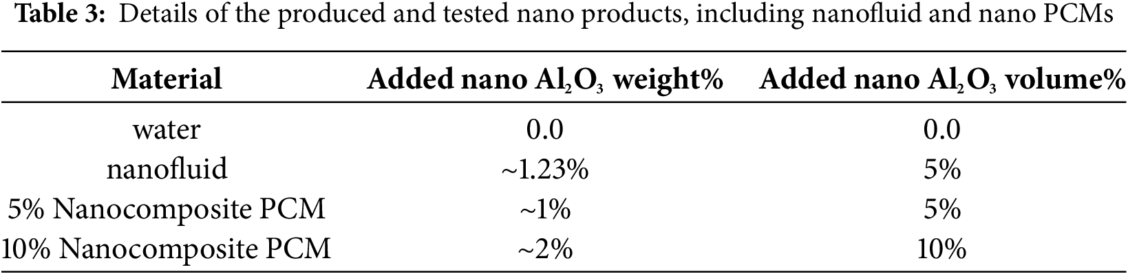
In this study, the ideal nanomaterial consists of two components: first, nanofluid containing water as its base fluid and second, nanocomposite based on octadecane paraffin. In both cases make use of Al2O3 nanoparticles, which have a density of 4 g/cm3 and an average size of 40 nm. The polynomial function of temperature is used to calculate the water’s characteristics. Table 2 shows the characteristics of organic materials on the octadecane molecular level.

The required properties of the nanofluid for analysis consist of thermal conductivity coefficient, viscosity, density, and specific heat capacity. The following relations have been used to calculate the nanofluid properties [36].
The density (
For the nanocomposite, the rules of mixtures have been used to predict the thermal and physical properties using Eqs. (6)–(8), where the paraffin wax is the matrix, whereas copper nanoparticles are the dispersed phase.
The density of composite,
Thermal conductivity of composite,
Specific heat of composite,
The nano concentrations used in the investigations are listed in Table 3.
To geometrically model the collector investigated in this research, SolidWorks software version 2022 is used. Based on the dimensions and sizes specified in the preceding chapter, the design of the collector commences with the lower box, thereafter, accompanied by the compartments linked to NPCEM, the copper plate, and the water transfer pipes or nano-encapsulated PCM, the air chamber, the tube holding box, and the glass cover, as illustrated in Fig. 2. In this figure, the explosion of all the components included in the construction of the collector are displayed.

Figure 2: Exploded view of the designed collector
Fig. 3 shows the assembled collector in SolidWorks software. After designing and assembling the collector, it is necessary to transfer this collection from SolidWorks software to ANSYS software so that other stages of analysis can be completed.

Figure 3: Collector assembly view
For the body of the collector, aluminum is considered, while for the plate that sits between the NPCM pipes and chambers, as well as the pipes themselves, copper is considered, and for the glass cover, glass is considered. The properties of these three materials are presented in Table 4.

The mass flow rate of water entering the collection pipes is 0.05 kg/s, with heat transfer and losses from the bottom and side surfaces of the collector disregarded.
2.4 Equations of Governance for the Water Channels
The first equation of motion describes the conservation of energy, and the second equation describes the momentum of an object in free fall. Power transmission using displacement and diffusion, as well as inertia and viscous forces, continue to play important roles. The equations as referenced by [30] for this model can be written as follows:
Conservation of mass equations:
In the x direction, the Navier-Stokes equation:
Energy equation:
The energy equation for the encapsulated PCM:
The subscript “s” indicates solid or encased PCM. The energy equation for the solid-liquid interface in the melting process is expressed as follows:
where s is the solid-liquid phase change interface. n is the normal to the solid-liquid interface and L is the latent heat of fusion of the PCM. In the freezing process, the subscripts l and s are interchanged, and the latent heat of fusion L is replaced by -L in the equation.
In this computational investigation, the selected boundary conditions are the ambient temperature at 25°C, the freezing and melting points of octane between 30°C and 35°C, a time step of 10 s in the solution of the PCM governing equations, for a time of 24 h. The solution of the governing equations has been performed in the ANSYS Fluent environment after discretization. The rest of the investigation results have considered the collector to be situated in Baghdad, Iraq, with latitude and longitude of 44.361488 and 33.312805, respectively.
2.6 Performance Enhancement Criteria
Various relationships have been proposed in the literature to predict the performance enhancement criteria (PEC) of solar collectors, which all have a similar concept. The concept of this parameter is the ratio of the increase in heat transfer to the increase in pressure losses. In the current investigation, the criteria are shown in Eq. (14) using the enhanced Nusselt with nanocapsule PCM, Nu/Nu0 compared to the increase in pumping power determined by the friction factor ratio, (f/f0)1/3.
In the aforementioned connection, Nu and f respectively indicate the Nusselt number and friction coefficient; the subscript “0” denotes the collection in its state without PCM.
2.7 Collector Geometry in ANSYS
After moving the designed collector in ANSYS software, it is necessary to fill the parts of the geometry where the fluid is with a hypothetical material so that fluid can be attributed to that hypothetical material in the next step. For this purpose, a material environment is attributed to the inside of the tubes and the air chamber. The material environment attributed to the inside of the pipes is shown in Fig. 4.

Figure 4: The material environment attributed to the space inside the pipes
After importing the model to the ANSYS environment and creating the material environment of the components, it is necessary to discretize the geometry using the mesh environment in ANSYS FLUENT. Fig. 5 displays the mesh environment selected in ANSYS FLUENT.

Figure 5: Selecting the mesh environment in ANSYS FLUENT
In the mesh generation environment, pyramidal and cubic elements are available to perform the discretization of the collector, as shown in Fig. 6. To improve the accuracy of the calculated results, pyramidal and cubical elements are selected from 10-node and 20-node types, respectively.

Figure 6: Schematic view of the elements applied to the collector. (a): Cubic, (b): Pyramidal
Following the preliminary steps of the simulation, it is essential to mitigate the impact of the shape and dimensions of the elements on the results to ensure their correctness. Mesh convergence process must be conducted for both permitted element types in collector analysis (cubic and pyramidal elements) under identical conditions, ensuring that the dimensions of the elements are sufficiently altered until they cease to change within a specific interval. With minimal impact on the value change of the estimated parameter or parameters, the results could be considered converged to a specific value of changes. By the specified boundary constraints, the mesh convergence procedure was executed for both pyramidal and cubic elements, with the resulting data illustrated in Figs. 7 and 8. The two graphs illustrate the average temperature of the water exiting the collection pipe for both types of components across various dimensions. Increasing the size of the cubic elements results in a continuously fluctuating average temperature for the water exiting the collector, as shown in Fig. 7, which fails to stabilize within any interval. This issue suggests that employing these elements for analysis will yield inaccurate and unreliable results, as the dimensions of the utilized elements significantly influence the calculations derived from them.

Figure 7: The mean temperature of the water exiting the collector pipe utilizing cubic components
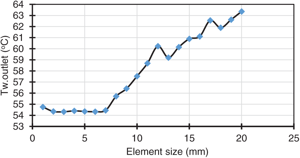
Figure 8: The mean temperature of the water exits the collector pipe utilizing pyramidal components
Fig. 8 illustrates that by diminishing the dimensions of the pyramidal elements utilized for the collector analysis to 7 mm, the results concerning the temperature of the water exiting the collector have converged to a specific value. The values acquired are similar, and the graph is level. This state signifies the independence of the findings from the problem’s network, referred to as the independence of the solution from the network. Therefore, the collector may analyze components measuring between 7 and 1 mm. Smaller element sizes lead to slower analysis speeds, but the results in that size range do not change much. Therefore, we conclude that the analysis uses pyramidal elements measuring 7 or 6 mm.
3.1 Validation of the Simulation Procedure
It is essential to compare the current results with those of prior studies to verify their accuracy and validity to validate the findings. For this purpose, the computationally developed and simulated model has been solved using the experimental data and boundary conditions of Mauricio et al. [35]. The comparison results of the simulation and the experimental results are shown in Fig. 9, which evidences the correctness of the developed computational procedure. The largest difference between the current simulation and the experiment of [35] is approximately 11%, and the mean relative percentage of differences is around 8%. As such, it is possible to assert that the research’s findings are accurate and reliable.

Figure 9: Validation of the results of the present study compared to Mauricio et al. [35]
3.2 Analysis of the Pipe’s Fluid Content
In the following, the contours and the results of fluid temperature changes and other related parameters inside the collector based on the sun’s radiation during the day hours of June 21 in Baghdad city are presented.
3.2.1 Temperature Analysis for the Absorbent Copper Plate
Fig. 10 shows how the temperature of the copper absorber plate changes normally. This plate is found between the chamber of the phase change material and the collecting tubes. The graphic shows that, although the numerical value of the copper absorber plate stays constant, the average temperature of the plate changes during the day, reflecting the trend of the water temperature exit the collector. After leaving the collector, copper seems to be somewhat warmer than the water temperature, which seems to be rather normal.

Figure 10: Changes in the copper absorber plate’s mean temperature
The prediction starts with conditions of solar and weather at 06:00 until 19:00. The copper absorbent plate reaches a high temperature of 62.49°C around 13:00. Due to the use of the nano-encapsulated phase changer, the copper absorber plate’s higher temperature ultimately matches the water in the collecting temperature.
3.2.2 Analysis of the Thermal Energy Storage Compartment
Octadiene, a nano-encapsulated phase transition material, is displayed and studied as its temperature distribution is tracked as water flows into the collecting tubes. Fig. 11 displays the temperature distribution within the 5% volume fraction used in the collector for a set hour in the nano-encapsulated phase change material. After moving away from the copper absorbent plate, the substance’s temperature drops until it reaches the midpoint of the lowest surface, as shown in Fig. 11. The material’s outermost layer exhibits the maximum temperature. At very low temperatures, donors undergo a phase shift. The issue arises due to the limited heat conductivity of paraffin wax. The lower parts of these chambers do not become hot enough to melt anything, while the upper parts get hot enough to transform solid to liquid. There is a drawback to using this material since the nano-encapsulated phase transition material cannot melt by the collector heat alone due to its low conductivity and relatively high melting point. This drawback could be considered a limitation in the simulation as the code’s energy-storing capabilities could not be utilized to their fullest extent because of this.

Figure 11: Distribution of temperature in a nano encapsulated phase transition material with a 5 wt.% fraction
Fig. 12 illustrates the graph depicting variations in average temperature for the 5% volume fraction of nano-encapsulated phase transition material. The average temperature changes of the nano-encapsulated materials show similar patterns to those of the copper plate and the fluid leaving the collector. This graphic, unlike the previous ones, presents numerical values where the maximum temperature is defined as the difference between the liquid’s maximum temperature at the collector and the copper plate’s maximum temperature at the absorber. Additionally, this area of the collector loses heat more slowly than other areas as it approaches the day’s middle hours. The PCM melts in small volumes and then refreezes when the solar irradiance reduces, which causes the temperature decrease process to go slowly.

Figure 12: Average temperature fluctuations in the nano-encapsulated phase change material with a 5 wt.% concentration
Fig. 13 shows three graphs showing the temperatures of the different parts: the phase transition material with nanoparticles inside, the absorbent copper plate, and the output fluid. At 5% volume, all three were recorded. The graph shows the nano-encapsulated phase transition material at a temperature that is intermediate between the fluid and the absorbent copper plates. The chemical’s graph rises above the other two as night falls because its temperature drops more and more.
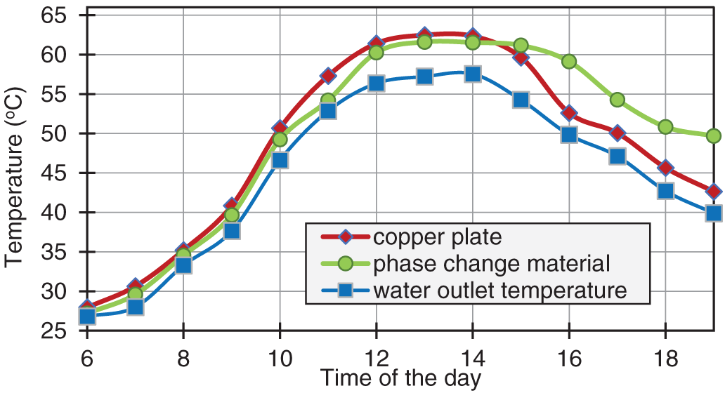
Figure 13: Outlet fluid’s temperature; average temperature of the absorbent copper plate; average temperature with 5 wt.% fraction nano encapsulated PCM
3.2.3 Comparison between Obtained and Experimental Results
The water outlet temperature from the collector in this investigation is compared to that from the 2017 experimental study by Mauricio et al. [35] in Fig. 14. From dawn till around 10 in the morning, the two plots are practically in sync, as seen on the graph. On the other hand, when midday draws near, the graph from this study is more significant than the experimental data from Mauricio et al. [35]. Since Iraq and Colombia had different topographies and solar radiation properties, the simulated collection location varied between the two countries. The tested collector was used in an experiment in Colombia. Water entering the collector in the afternoon cools down at a slower rate than in the morning, according to both graphs. Around 25% of the difference between these two sources of results happens at six o’clock in the evening. Additionally, there is a mean of 10–15% difference between these two graphs in the middle of the day.

Figure 14: Comparing the variations in temperature of the collector’s output water from the collector in the present work and the research of Mauricio et al. [35]
3.2.4 The Effect of Using Thermal Energy Storage
Fig. 15 shows, for the save/recovery cycle, the time differences in the collector’s outlet temperature in two modes, one with and one without a PCM. In both cases, the exit water temperature follows the same pattern. The two profiles have a phase difference; the temperature in the PCM mode reaches a high of 57.55°C at about 14:00, while the temperature in the second instance, without PCM, peaks at 65.7°C at 13:00. Less of the collector temperature in the PCM-equipped case rises during the day than in the PCM-free case. This different trend happens since most of the solar radiation is absorbed by the PCM to melt, therefore enabling latent heat retention. Consequently, the variation between the two highest temperatures determines the amount of heat that has been accumulated in both conditions. The outlet water temperature with PCM is higher than that without PCM after 15:00, suggesting that PCM can provide the same quantity of daytime heat storage.

Figure 15: Time variations in the collector’s outlet temperature in two scenarios, one with and without PCM
3.2.5 Impact of Volume Fraction of Nanocapsule
Examined in Fig. 16 is the impact of varying nanocomposite TES 5% and 10% by volume concentrations on the hot water’s temperature. The results show that using Nano encapsulated PCM instead of pure PCM, they were also able to generate hotter water. A volume proportion of 5% considerably increases the hot water pouring out of the outlet’s temperature. The nanoparticles may rapidly recover thermal energy in the evening since their capacity to store thermal energy is higher than that of conventional PCM in the morning. A small duration is spent in micro PCM at a higher temperature. Nano-encapsulating PCM helps to increase the conductive heat transfer from the copper pipe to the hot water output. This can be explained by the fact that the nano-PCM loaded in the chamber exhibits better energy storage during the charging process and, as a result, has a longer duration of hot water supply as the solar radiation reaches its peak. During the discharge procedure, it was heated. As a result, more heat can be stored during charging thanks to the inclusion of nano-PCM inside the housing. Due to PCM’s enhanced thermal conductivity, Nano encapsulated PCM can store more thermal energy than pure PCM. However, this rise in PCM volume percentage has the potential to lower the hot water outlet temperature. In actuality, the exit hot water temperature is lowered by a volume fraction content of 10% PCM. The volume fraction of 5% is, therefore, more than the volume fraction of 10%. Therefore, it can be said that the increase in volume fraction is not random.

Figure 16: Transient behavior of hot water outlet temperature with and without adding Al2O3 nanoparticles to the PCM
3.2.6 Collector Performance with Various Nanocapsule PCM Concentrations
Fig. 17 depicts the variations in the collector’s PEC for 0%, 5%, and 10% volume fractions of nanomaterials in the PCM about the mass flow rate of the nanofluid. The effectiveness of the collector is decreasing as the mass flow rate rises. Additionally, a volume percentage of 5% and a mass flow rate of 0.05 kg/s result in the best efficiency. The nanocomposite PCM stores the heat and then delivers it to the nanofluid while passing through the collector. The lowest mass flow rate and highest volume fraction have both been reported to have a maximum coefficient of performance of 1.4. The coefficient of performance exhibits a declining trend as the nanofluid mass flow rate increases and particle concentration decreases. Using nanoencapsulated TES makes the system perform better than using plain water as the working fluid. The performance measurements for the nanocapsule are above one. However, this performance enhancement is more substantial for lower mass flow rates. It is recommended to use low flow rates to better capture heat from solar energy and the nano-encapsulated PCM, while also minimizing friction losses in the pipes.
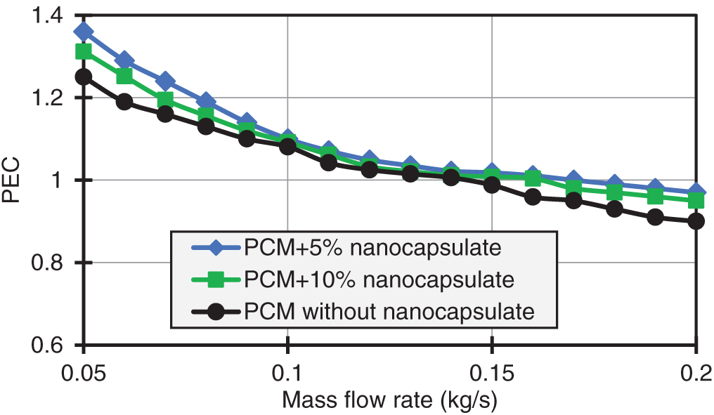
Figure 17: Changes in performance evaluation criteria of the collector versus fluid mass flow rate
3.2.7 Distribution of Pressure Inside Collector Pipes
Fig. 18 shows the pressure changes inside the collector pipes. In this figure, it can be seen that contrary to the trend of temperature increase shown in the previous section, the fluid pressure inside the collector pipes, as it approaches the outlet section, continuously decreases. This pressure reduction continues until the output fluid pressure becomes equal to the atmospheric pressure, which is visible in the Makor figure. Therefore, the pressure in the inlet pipe, specifically in the entrance of the fluid into the collector has its maximum pressure value and has a minimum value at the outlet from the collector. The reduction in pressure is due to the frictional and minor losses during the fluid flow inside the piping system of the collector.

Figure 18: Pressure contour inside collector tubes
This study numerically examines the influence of nano-encapsulated PCM on the performance of a compacted solar water heater. The most significant findings of this study are:
• The temperature of the outflow fluid is at its highest between 12:00 and 14:00, and during this time, it is nearly constant.
• In the morning, the temperature of the nano-encapsulated PCM is between the temperature of the fluid leaving the collection area and the absorbent copper plate. Nevertheless, this chemical’s temperature graph increases above that of the other two compounds as its temperature gradually decreases in the evening.
• One disadvantage of employing this material is that due to low conductivity and a relatively high melting temperature, the heat produced in the collector is not enough to melt the nano-encapsulated phase change material. This prevents the analysis from using the complete capacity of the code for energy storage.
• The optimal percentage of nanoparticles in PCM is 5%. Increasing the volume fraction of nanoparticles in phase change materials (PCM) does not always improve the collector performance.
It is recommended to carry out future research to improve and complete the results of this research. The following suggestions are offered:
• Use of nanofluid instead of water as the collector fluid
• Using other phase change materials and investigating their effect on the performance of the collector
• Use of turbulator in the fluid path of the collector
• Using other arrangements for pipes, such as circular arrangements
Acknowledgement: We would like to thank all collaborators who have made outstanding contributions to this article. In particular, the authors are grateful to the ICSSD2024 Technical Committee.
Funding Statement: The authors received no specific funding for this study.
Author Contributions: The authors confirm their contribution to the paper as follows: Study conception and design: Malik A. Faisal, Alireza Saraei; data collection: Malik A. Faisal; analysis and interpretation of results: Malik A. Faisal; draft manuscript preparation: Malik A. Faisal; supervision: Alireza Saraei. All authors reviewed the results and approved the final version of the manuscript.
Availability of Data and Materials: All relevant data are included within the paper.
Ethics Approval: Not applicable.
Conflicts of Interest: The authors declare no conflicts of interest to report regarding the present study.
Nomenclature
| Cp | Specific heat capacity (J/kg·K) |
| f | friction factor (-) |
| h | coefficient of convective heat transfer (W/m2·K) |
| k | Coefficient of thermal conductivity (W/m·K) |
| FPC | Flat plate collector |
| NEPCM | Nano-encapsulated phase change materials |
| Nu | Nusselt number |
| PCM | Phase change materials |
| PEC | Performance enhancement criteria |
| TES | Thermal energy storage |
| Density (kg/m3) | |
| The volume fraction of nanoparticles in nanofluid or nanocomposite (%) | |
| The weight fraction of nanoparticles in nanofluid or nanocomposite (%) |
References
1. Al-Kayiem HH, Alhamdo MH. Thermal behavior of encapsulated phase change material energy storage. J Renew Sustain Energy. 2012;4(1):013112. doi:10.1063/1.3683532. [Google Scholar] [CrossRef]
2. Afolabi LO, Ariff ZM, Megat-Yusoff PSM, Al-Kayiem HH, Arogundade AI, Afolabi-Owolabi OT. Red-mud geopolymer composite encapsulated phase change material for thermal comfort in built-sector. Sol Energy. 2019;181:464–74. doi:10.1016/j.solener.2019.02.029. [Google Scholar] [CrossRef]
3. Jahangiri A, Ahmadi O. Numerical investigation of enhancement in melting process of PCM by using internal fins. J Therm Anal Calorim. 2019;137(6):2073–80. doi:10.1007/s10973-019-08098-8. [Google Scholar] [CrossRef]
4. Al-Kayiem HH, Lin SC. Performance evaluation of a solar water heater integrated with a PCM nanocomposite TES at various inclinations. Sol Energy. 2014;109(8):82–92. doi:10.1016/j.solener.2014.08.021. [Google Scholar] [CrossRef]
5. Sheikholeslami M. Solidification of NEPCM under the effect of magnetic field in a porous thermal energy storage enclosure using CuO nanoparticles. J Mol Liq. 2018;263(7):303–15. doi:10.1016/j.molliq.2018.04.144. [Google Scholar] [CrossRef]
6. Afolabi LO, Al-Kayiem HH, Aklilu TB. On the nano-additive enhanced flat plate solar collector integrated with thermal energy storage. Nanosci Nanotechnol Asia. 2017;7(2):172–82. doi:10.2174/2210681207666170301143038. [Google Scholar] [CrossRef]
7. Ghalambaz M, Doostanidezfuli A, Zargartalebi H, Chamkha AJ. MHD phase change heat transfer in an inclined enclosure: effect of a magnetic field and cavity inclination. Numer Heat Transf Part A Appl. 2017;71(1):91–109. doi:10.1080/10407782.2016.1244397. [Google Scholar] [CrossRef]
8. Ghalambaz M, Doostani A, Chamkha AJ, Ismael MA. Melting of nanoparticles-enhanced phase-change materials in an enclosure: effect of hybrid nanoparticles. Int J Mech Sci. 2017;134(9):85–97. doi:10.1016/j.ijmecsci.2017.09.045. [Google Scholar] [CrossRef]
9. Liu C, Rao Z, Zhao J, Huo Y, Li Y. Review on nanoencapsulated phase change materials: preparation, characterization and heat transfer enhancement. Nano Energy. 2015;13(Part B):814–26. doi:10.1016/j.nanoen.2015.02.016. [Google Scholar] [CrossRef]
10. Hawlader MNA, Uddin MS, Zhu HJ. Preparation and evaluation of a novel solar storage material: microencapsulated paraffin. Int J Sol Energy. 2000;20(4):227–38. doi:10.1080/01425910008914357. [Google Scholar] [CrossRef]
11. Al-Kayiem HH, Owolabi AL. Enhancement techniques for solar energy technologies chapter 4. In: Picón-Núñez M, editor. Solar collectors: applications and performance. New York, NY, USA: NOVA Science Publisher; 2018. [Google Scholar]
12. Naghdbishi A, Yazdi ME, Akbari G. Numerical study on the performance of a glazed photovoltaic thermal system integrated with phase change material (GPVT/PCMon the contribution of PCM volumetric fraction and environmental temperature; arXiv:2105.14827. 2021. doi:10.48550/arXiv.2105.14827. [Google Scholar] [CrossRef]
13. Elarem R, Alqahtani T, Mellouli S, Aich W, Ben Khedher N, Kolsi L, et al. Numerical study of an evacuated tube solar collector incorporating a Nano-PCM as a latent heat storage system. Case Stud Therm Eng. 2021;24:100859. doi:10.1016/j.csite.2021.100859. [Google Scholar] [CrossRef]
14. Al-Zurfi HA, Ali Talib M, Hassan QH, Aljabri GJ. A numerical study to improve the efficiency of solar collector used for water heating using phase change material. J Adv Res Numer Heat Transf. 2024;17(1):1–13. doi:10.37934/arnht.17.1.113. [Google Scholar] [CrossRef]
15. Faisal MA, Rahmani A, Akrami M. Numerical investigation of solar collector performance with encapsulated PCM: a transient, 3D approach. Energies. 2024;17(21):5243. doi:10.3390/en17215243. [Google Scholar] [CrossRef]
16. Bharathiraja R, Ramkumar T, Selvakumar M, Sasikumar K. Experimental and numerical analysis of hybrid nano-enhanced phase change material (PCM) based flat plate solar collector. J Energy Storage. 2024;96:112649. doi:10.1016/j.est.2024.112649. [Google Scholar] [CrossRef]
17. Karami M, Shahini N, Ali Akhavan Behabadi M. Numerical investigation of double-walled direct absorption evacuated tube solar collector using microencapsulated PCM and nanofluid. J Mol Liq. 2023;377(1):121560. doi:10.1016/j.molliq.2023.121560. [Google Scholar] [CrossRef]
18. Su JF, Wang LX, Ren L. Preparation and characterization of double-MF shell microPCMs used in building materials. J Appl Polym Sci. 2005;97(5):1755–62. doi:10.1002/app.21205. [Google Scholar] [CrossRef]
19. Mofijur M, Mahlia T, Silitonga A, Ong H, Silakhori M, Hasan M, et al. Phase change materials (PCM) for solar energy usages and storage: an overview. Energies. 2019;12(16):3167. doi:10.3390/en12163167. [Google Scholar] [CrossRef]
20. Lin SC, Al-Kayiem HH. Thermal reliability of paraffin wax phase change material for thermal energy storage. Appl Mech Mater. 2014;699:263–8. doi:10.4028/www.scientific.net/amm.699.263. [Google Scholar] [CrossRef]
21. Lin SC, Al-Kayiem HH. Thermophysical properties of nanoparticles-phase change material compositions for thermal energy storage. Appl Mech Mater. 2012;232:127–31. doi:10.4028/www.scientific.net/amm.232.127. [Google Scholar] [CrossRef]
22. Owolabi AL, Al-Kayiem HH, Baheta AT. Nanoadditives induced enhancement of the thermal properties of paraffin-based nanocomposites for thermal energy storage. Sol Energy. 2016;135(11):644–53. doi:10.1016/j.solener.2016.06.008. [Google Scholar] [CrossRef]
23. Al-Kayiem HH, Lin SC, Owolabi AL, inventors. Nano PCM-integrated solar water heater. Malaysia patent MyiPO PI 2013001609; 2013 May 3. [cited 2025 Jan 1]. Available from: https://iponlineext.myipo.gov.my/SPHI/Extra/IP/Mutual/Browse.aspx?sid=638643308708280148. [Google Scholar]
24. Alisetti EL, Roy SK. Forced convection heat transfer to phase change material slurries in circular ducts. J Thermophys Heat Transf. 2000;14(1):115–8. doi:10.2514/2.6499. [Google Scholar] [CrossRef]
25. Park S, Lee Y, Kim YS, Lee HM, Kim JH, Cheong IW, et al. Magnetic nanoparticle-embedded PCM nanocapsules based on paraffin core and polyurea shell. Colloids Surf A Physicochem Eng Aspects. 2014;450:46–51. doi:10.1016/j.colsurfa.2014.03.005. [Google Scholar] [CrossRef]
26. Kürklü A, Özmerzi A, Bilgin S. Thermal performance of a water-phase change material solar collector. Renew Energy. 2002;26(3):391–9. doi:10.1016/S0960-1481(01)00130-6. [Google Scholar] [CrossRef]
27. Papadimitratos A, Sobhansarbandi S, Pozdin V, Zakhidov A, Hassanipour F. Evacuated tube solar collectors integrated with phase change materials. Sol Energy. 2016;129:10–9. doi:10.1016/j.solener.2015.12.040. [Google Scholar] [CrossRef]
28. Allouhi A, Ait Msaad A, Benzakour Amine M, Saidur R, Mahdaoui M, Kousksou T, et al. Optimization of melting and solidification processes of PCM: application to integrated collector storage solar water heaters (ICSSWH). Sol Energy. 2018;171(20):562–70. doi:10.1016/j.solener.2018.06.096. [Google Scholar] [CrossRef]
29. Badiei Z, Eslami M, Jafarpur K. Performance improvements in solar flat plate collectors by integrating with phase change materials and fins: a CFD modeling. Energy. 2020;192(9):116719. doi:10.1016/j.energy.2019.116719. [Google Scholar] [CrossRef]
30. Syahruddin AS, Jalaluddin J, Hayat A. Performance analysis of solar water heating system with plate collector integrated pcm storage. EPI Int J Eng. 2020;3(2):143–9. doi:10.25042/epi-ije.082020.09. [Google Scholar] [CrossRef]
31. Pawar VR, Sobhansarbandi S. Design optimization and heat transfer enhancement of energy storage based solar thermal collector. Sustain Energy Technol Assess. 2021;46(5):101260. doi:10.1016/j.seta.2021.101260. [Google Scholar] [CrossRef]
32. Li B, Zhai X. Experimental investigation and theoretical analysis on a mid-temperature solar collector/storage system with composite PCM. Appl Therm Eng. 2017;124(2):34–43. doi:10.1016/j.applthermaleng.2017.06.002. [Google Scholar] [CrossRef]
33. Li B, Zhai X, Cheng X. Experimental and numerical investigation of a solar collector/storage system with composite phase change materials. Sol Energy. 2018;164(8):65–76. doi:10.1016/j.solener.2018.02.031. [Google Scholar] [CrossRef]
34. Kumar PM, Mylsamy K. A comprehensive study on thermal storage characteristics of nano-CeO2 embedded phase change material and its influence on the performance of evacuated tube solar water heater. Renew Energy. 2020;162(11):662–76. doi:10.1016/j.renene.2020.08.122. [Google Scholar] [CrossRef]
35. Carmona M, Palacio M, Martínez A. Experimental analysis of a flat plate solar collector with integrated latent heat thermal storage. J Contemp Urban Aff. 2017;1(3):7–12. doi:10.25034/ijcua.2018.36zd72. [Google Scholar] [CrossRef]
36. Shamshirgaran SR, Al-Kayiem HH, Sharma KV, Ghasemi M. State of the art of techno-economics of nanofluid-laden flat-plate solar collectors for sustainable accomplishment. Sustainability. 2020;12(21):9119. doi:10.3390/su12219119. [Google Scholar] [CrossRef]
Cite This Article
 Copyright © 2025 The Author(s). Published by Tech Science Press.
This work is licensed under a Creative Commons Attribution 4.0 International License , which permits unrestricted use, distribution, and reproduction in any medium, provided the original work is properly cited.
 Downloads
 Citation Tools