
 Submit a Paper
 Propose a Special lssue
 Open Access
ARTICLE

Effect of Nanoparticles and Biodiesel Blended with Diesel on Combustion Parameters in Compression Ignition Engine: Numerical Analysis
1 Department of Mechanical Engineering, Faculty of Engineering, Karabük University, Karabük, 78050, Turkey
2 Training and Workshop Center, University of Technology-Iraq, Baghdad, 35050, Iraq
* Corresponding Author: Hasanain A. Abdul Wahhab. Email:
(This article belongs to the Special Issue: Advancements in Energy Resources, Processes, Systems, and Materials-(ICSSD2024))
Energy Engineering 2025, 122(5), 2059-2075. https://doi.org/10.32604/ee.2025.061592
Received 28 November 2024; Accepted 18 February 2025; Issue published 25 April 2025
 View Full Text
 Download PDF
Abstract
The current work includes a numerical investigation of the effect of biodiesel blends with different aluminum oxide nanoparticle concentrations on the combustion process in the cylinder of a diesel engine. IC Engine Fluent, a specialist computational tool in the ANSYS software, was used to simulate internal combustion engine dynamics and combustion processes. Numerical analysis was carried out using biodiesel blends with three Al2O3 nanoparticles in 50, 100, and 150 ppm concentrations. The tested samples are called D100, B20, B20A50, B20A100, and B20A150 accordingly. The modeling runs were carried out at various engine loads of 0, 100, and 200 Nm at a rated speed of 1800 rpm. The combustion characteristics are improved due to the catalytic effect and higher surface area of nano additives. The results showed the improvements in the combustion process as the result of nanoparticle addition, which led to the higher peak cylinder pressure. The increases in the peak cylinder pressures for B20A50, B20A100, and B20A150 about B20 were 3%, 5%, and 8%, respectively, at load 200 Nm. The simulation found that the maximum temperature for biodiesel blends diesel was higher than pure diesel; this was due to higher hydrocarbon values of B20. Also, nano-additives caused a decrease in temperatures in the combustion of biofuels.Keywords
One of the potential approaches to improving diesel engine performance is the addition of nanomaterials, which has been recently studied. This approach aims to increase the combustion characteristics of diesel fuel through these additives, which results in improved engine efficiency. Many studies have addressed the effect of nanoparticles on diesel engine performance, which will be presented in this section [1]. The uses of diesel engines have varied, including freight vehicles, public transportation buses, and electricity generators that provide emergency power, in addition to those used in agricultural operations to provide food [2,3]. Moreover, diesel fuel is considered the most widely used energy source in industrial processes. On the other hand, it is one of the causes of harmful effects through gases emitted from engines on the human environment and crops [4]. Environmentally, exhaust gases are the pollutants that pose a major threat to human health. Statistics show that these pollutants contain more than 40 toxic and air-polluting substances. The materials and products included in diesel engine emissions were classified to include carbon dioxide (CO2), hydrocarbon (HC), nitrogen oxide (NOx), particulate matter (PM), and other gases, and the effects and identification of 600 million important factors caused by exhaust gases were recorded. This also coincides with the impact of these emissions on climate change directly, especially on patients suffering from chronic diseases: such as asthma, chronic bronchitis, and other lung diseases. These effects also extend beyond human health through their impact on the outer ozone layer within the atmosphere [5]. Many solutions have been addressed by scientists and researchers to reduce the effects of these emissions on the environment [6,7]. These solutions included direct methods, through improving the combustion of diesel fuel, or indirect methods, through adopting systems to address these emissions after combustion [8,9].
Detailed combustion mechanism was studied as a new process to develop diesel engines [10,11] operating with biodiesel blends with nanomaterials. The interaction between soot particles and NOx was described, and reported that the influence of soot on NOx depends not only on radiation from the thermal process but also on reaction due to the chemical process [12]. The bio-diesel blends with nanomaterials were tested on the diesel engine, and experimental results were compared with simulated results. Numerical analysis showed a significant increase in peak pressure and exhaust temperature due to the increase in ignition delay and the heat release rate in the combustion phase with nanoparticles. Also, a study suggested the advanced injection timing for diesel engine operation with biofuels [13]. The enhancement by iron oxide and Fe3O4 nanoparticles in diesel and biodiesel-diesel blends has been experimentally investigated to study the performance and emissions of a single-cylinder diesel engine [14]. Enhancement in engine performance is detected with the addition of 10 PPM Fe3O4 nanoparticles, and the Fe3O4 nanoparticles in the fuel blend results demonstrated a reduction of HC, CO, and NOx emissions.
On the other hand, recent research confirms that the air-fuel mixing ratio can be distributed appropriately with the special piston cavity driving the airflow [15]. Several studies have discussed the geometric arrangement of a new natural gas engine and the effect of mixing air and fuel inside the cylinder with the geometry of the combustion chamber, injection conditions, type of injector, and shape of the cylinder head. Generally, swirl and turbulence control the mixing and combustion of air/fuel within the cylinder of diesel engines. The inlet port design plays a major role in swirl motion; thus, well-optimized combustion can be achieved [16]. Mitchell et al. [17] studied engine blow-by and its effect on brake power, friction power, and different parameters. Results appeared that neat diesel produces higher blow-by than the oxygenated fuels, while it was proved that oxygenated fuels perform better between hot and cold start when compared to diesel. microalgae HTL surrogate fuels were used to enhance engine performance and reduce exhaust emissions. The compared study was implemented on a series of turbo-charged diesel engines, multi-cylinders, and common-rail [18].
In the last few years, numerical analysis using different programs was used to study diesel engines by researching alternative fuels and their effect on performance characteristics and analyzing the components of polluting exhaust gases. On the other hand, a few studies have been conducted on diesel engine simulations operating with biodiesel blends and nanomaterials. This work focused on CFD simulation of diesel engines using diesel and waste cooking oil blended biodiesel with Al2O3 nanoparticles. The cylinder pressure, temperature distribution, and velocity are found. This article presents the methodology for constructing the numerical field, describing it, and applying the boundary conditions.
Internal combustion engine fluid dynamics and combustion processes have been simulated using IC Engine Fluent, a specialist computational tool in the ANSYS software. It gives engineers and scientists a thorough platform to evaluate and improve the performance, emissions, and efficacy of numerous internal combustion engine types utilized in industrial, automotive, and aerospace applications. Complex systems known as internal combustion engines use fuel burning in a small area to generate mechanical work. The fluid dynamics inside them largely determine these engines’ pressure, velocity, and temperature. Fig. 1 presents numerical analysis processes.
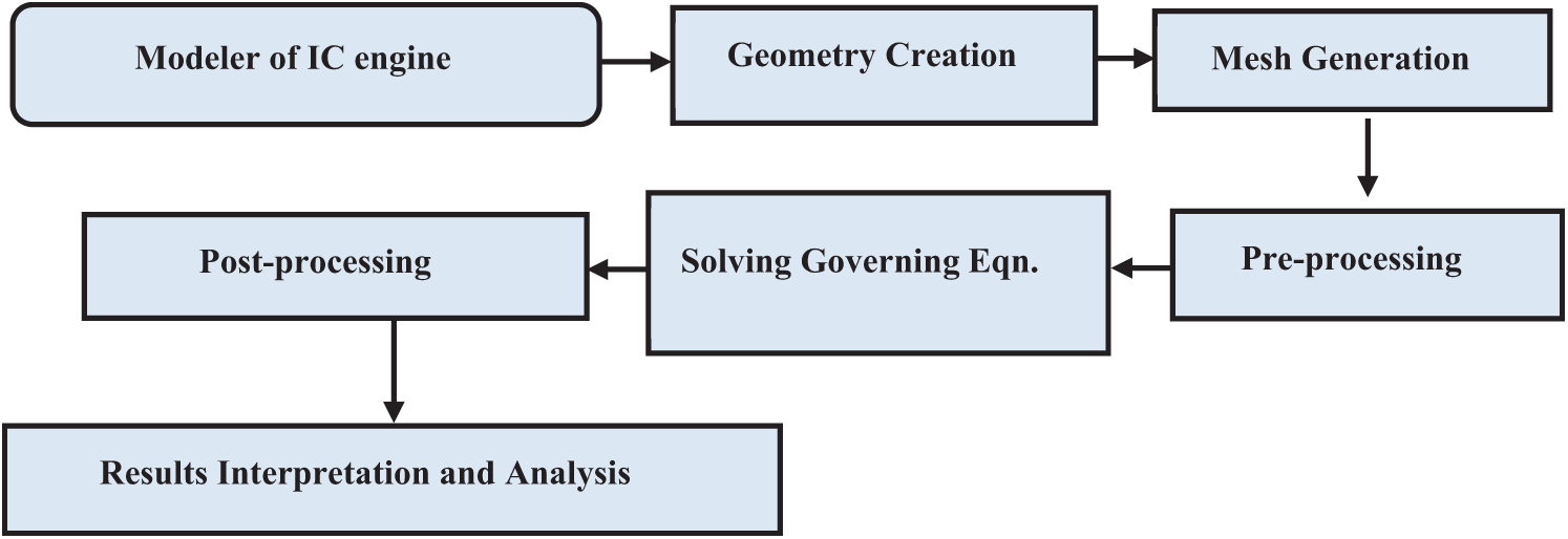
Figure 1: Numerical analysis flowchart
2.1 Compression Ignition Engine
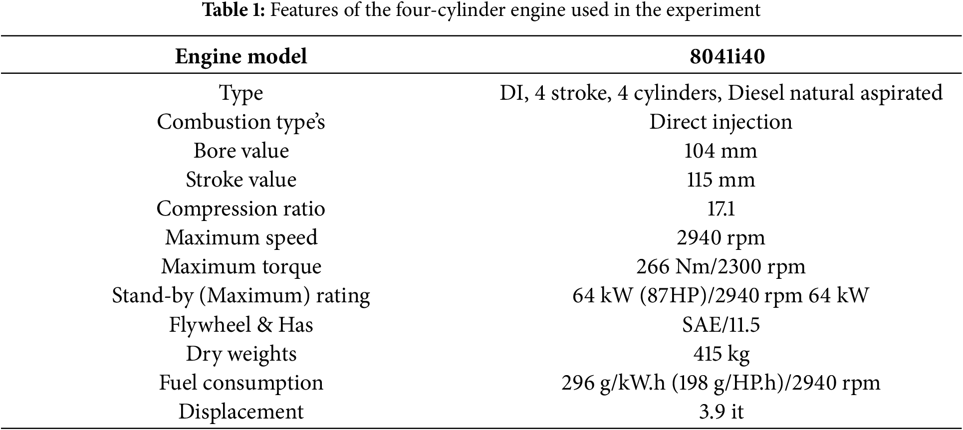
The study was performed using experimental data of a four-cylinder IC engine to build the computational model is shown in Fig. 2. Four cylinders and four stroke types were used (8041 i40, direct injection); the detailed specifications of the base engine selected for the simulation are given in Table 1.
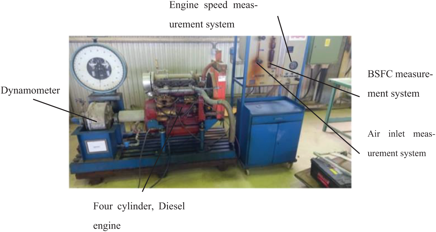
Figure 2: Experimental setup visualization
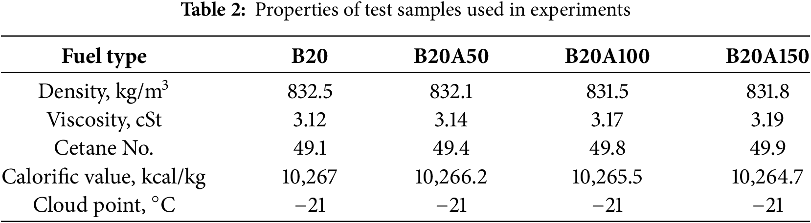
Biodiesel data from waste cooking oil were chosen for blending with test samples. This simulation focused on four samples: B20 (extracted from 20% waste cooking oil biodiesel with 80% neat diesel based on volume), B20A50, B20A100, and B20A150 (the Al2O3 nanoparticles were blended with B20 samples at the dosages of 50, 100, and 150 ppm of the mass fraction). The physic-chemical properties of all the considered fuel samples are measured as per ASTM standards, and the results are offered in Table 2.
The experiments were conducted by the Department of Power Mechanics Technology, Al-Furat Al-Awsat Technical University/Al-Musayyab Technical Institute, on a four-cylinder engine, four-stroke, water-cooled, direct injection diesel, and naturally air intake, while a speed sensor was used to gauge the engine speed; it operates depend on pulse counting principle. A calibrated vessel as well as a stopwatch were used to measure the fuel consumption rate. The inlet airflow was determined using an orifice meter. A pressure manometer was installed between the intake manifold and the orifice meter. The engine was connected to a water dynamometer to measure the torque.
The methodology adopted for the present study was as follows.
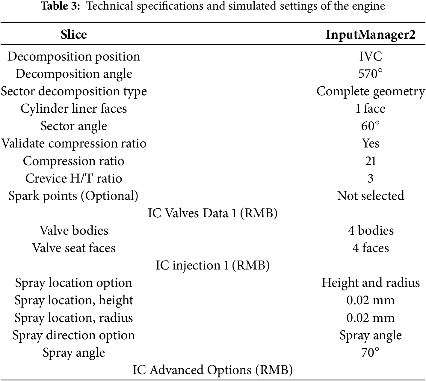
Users of IC Engine Fluent may design intricate 3D geometries of various engine parts, including cylinders, pistons, valves, and combustion chambers. Users of Solid Work may design intricate 3D geometries of various IC engine parts. The accuracy of the simulation results is guaranteed by geometry modeling accuracy. As shown in Fig. 3, the dimensions of the combustion chamber were created considering earlier studies about piston diameter, crankshaft length, and other factors, as shown in Table 3. The IC Engine Fluent feature in the ANSYS software was utilized to perform the simulation.
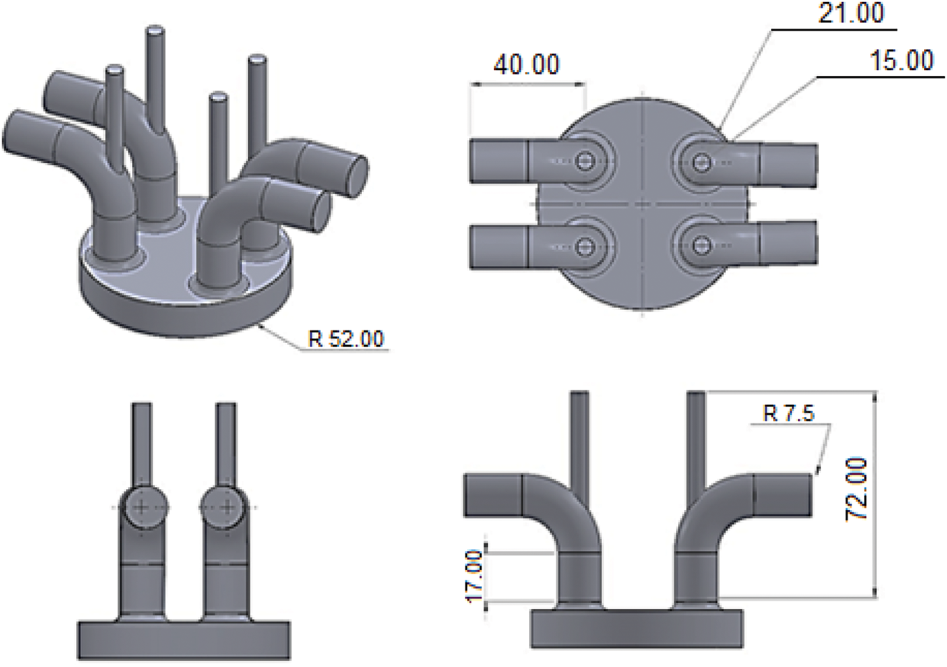
Figure 3: Cylinder geometry of internal combustion engine
After entering the required information as shown in Fig. 3, the input manager converts the model of the internal combustion chamber into a geometry that can be simulated to extract the results as in Fig. 4. Where the data such as crankshaft length 115 mm and minimum lift 0.2 mm and the input option for inlet valve closed (IVC) and the exhaust valve open (EVO) is entering direct values, the inlet valve closed 570 degrees and the exhaust valve open 833 degrees.
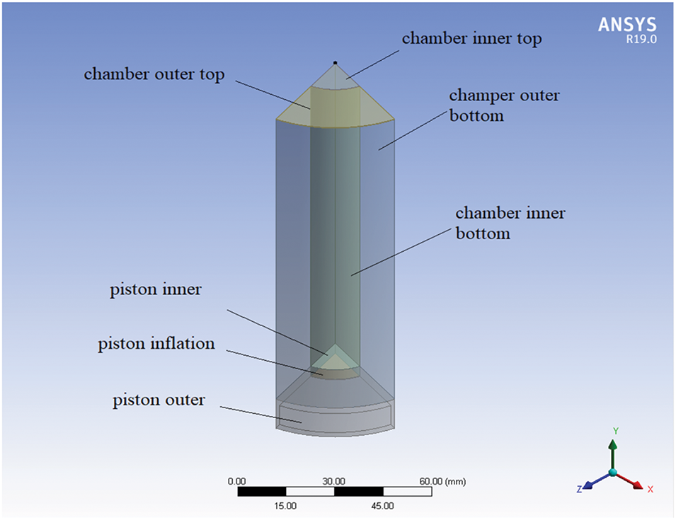
Figure 4: IC engine domain
In general, structured meshes are the best choice for modeling complex geometric designs, which is why the hexagonal structured mesh is adopted in the current modeling. ANSYS software is qualified to create solid geometric meshes and 3D models and drive IC fluently. The number of cells taken is shown in Fig. 5.
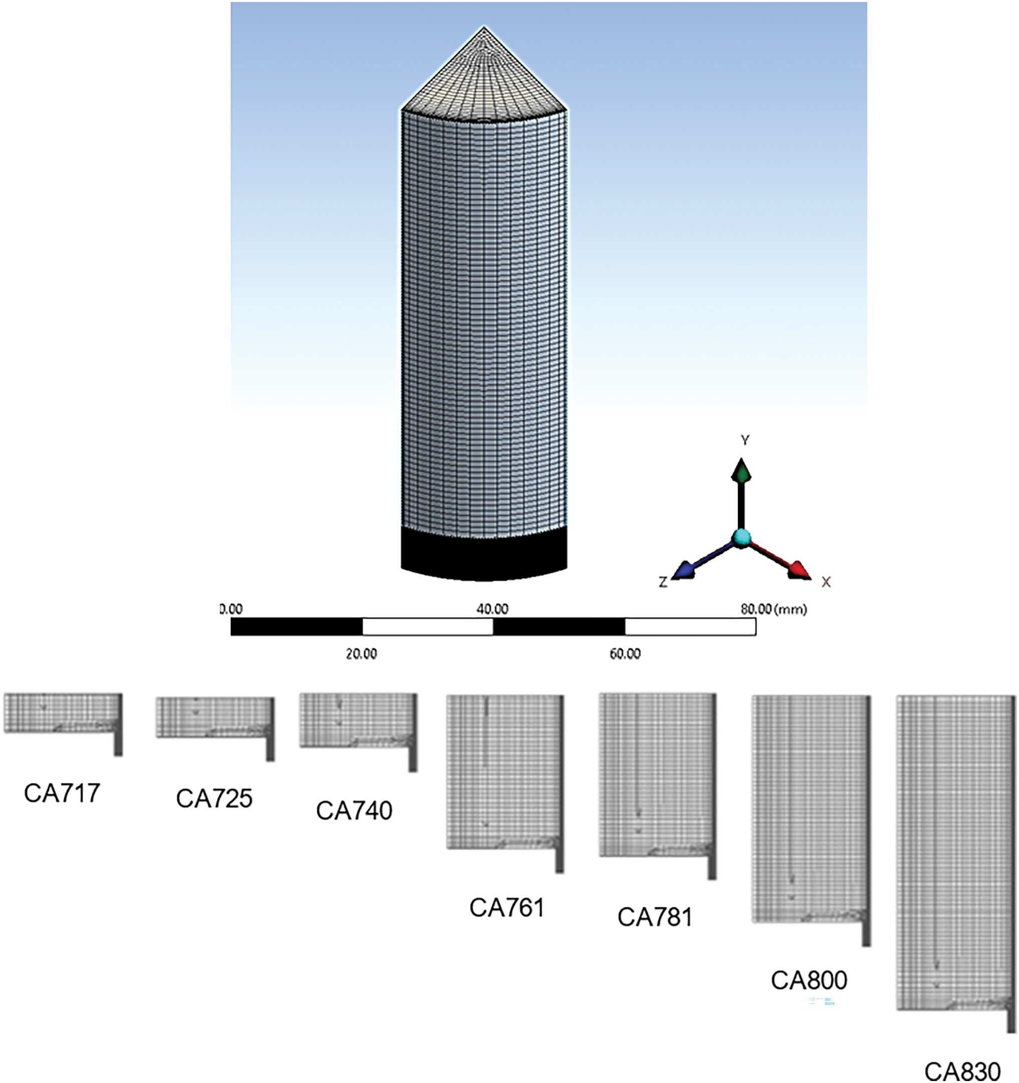
Figure 5: Mesh generated
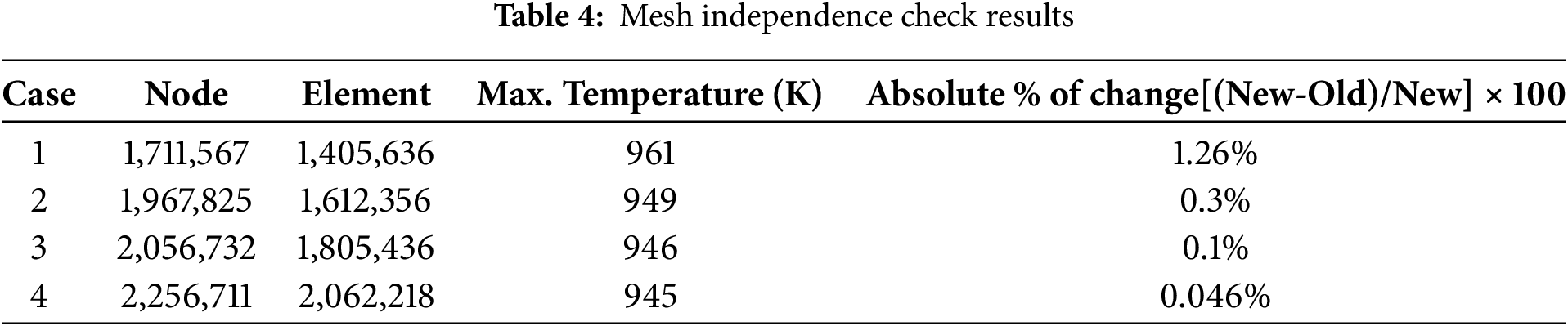
For accurate and reliable results, the combustion domain is meshed with adopting tetrahedral, structure-based, and path-conforming meshing because of generally provides higher accuracy and efficiency for certain simulations, has a regular grid structure with well-defined layers, is suitable for complex geometries with multiple faces and regions and maintains the integrity of original geometry, the size of the element used was 0.001 m, as shown in Table 4.
The CFD model was controlled by several assumptions;
The working fluid used is considered an ideal gas.
• The piston was considered flat during modeling.
• Only one valve was used for the inlet and exhaust process within the simulation.
• The adiabatic process was adopted, and its equality was adopted during compression and expansion.
• Assume that the inlet valve at the suction stroke opens at 0° to 180°, while the exhaust valve opens at 710° to 890° during the exhaust stroke.
The spark is often under-resolved on the CFD mesh because the initial spark size is typically modest compared to the cell size. Modeling the spark by burning a few cells close to the spark position reveals considerable grid and time-step sensitivity, and flame speed and flame brush diffusion may be inaccurate owing to poor space and time resolution. Additionally, ignitions happen too soon when the initial spark is lower than the size of the cell. The ANSYS IC engine fluently calculates a sub-grid equation for the spark evolution to lessen this sensitivity. The main assumptions of the governing equations are incompressible, unsteady, and 3D dimensions. The flame front of the spark is infinitely thin and completely spherical. Spark radius, r, increases with time, t [19],
Continuity equation:
Momentum equation:
Energy equation:
where
where Δ is the cell length scale,
An alternative is to use the spark-model text interface to provide
Since the flame speed is influenced by all of the turbulent scales present after the spark diameter reaches this size,
where
These musical arrangements are constant in time and consistent in space. Spark energy is unnecessary to ignite the mixture because the thermo-chemical condition behind the spark flame front is instantly equilibrated as the spark propagates. All combustion models start with the spark energy set to zero and the burned temperature as the equilibrium temperature. However, the temperature behind the spark may be changed via the user interface to a positive number, in which case the equilibrium temperature will be greater [19,20]. The turbulent flame speed is determined using the Turbulent Curvature model as follows:
where r is the current spark radius, D is the laminar diffusivity, and
Remember that the flame curvature reduces the speed of both laminar and turbulent flames. Since the user inputs the initial spark radius
This means that the Turbulent Length model disregards how flame curvature affects flame speed. The Herweg and Maly model is used to compute the turbulent flame velocity [20,21].
where
The chemical balance within combustion processes can be analyzed to determine the types of products. This is done by determining the fuel and air mixing ratios within a range known as the equivalent ratio. After the combustion of the mixed charge, the combustion products reach equilibrium at a certain pressure and temperature. The thermodynamic properties of the resulting mixture were determined through the combustion equation.
Fuel is injected directly into the cylinder using a fuel injector, and this unit is responsible for homogeneous fuel injection. The simulation system regulates fuel injection modeling by determining the injection time and the duration of the injector opening to control the amount of fuel charge supplied accurately. Fuel injection includes two methods: stratified injection and homogeneous injection. When the engine is running at a low load, early injection (stratified charge) is applied. This method injects fuel into the cylinder during the compression stroke. During high engine load, a homogeneous charge is applied in which the fuel charge is injected during the intake stroke to obtain a homogeneous mixture early [7].
Boundary conditions are crucial for setting up a realistic and accurate simulation of an internal combustion engine using ANSYS Fluent. They define the interaction of the engine with its surroundings and play a pivotal role in capturing the engine’s behavior. Further boundary conditions are applied based on valve position as follows.
1. Inlet BC (subsonic, Mach number less than 1)
2. Outlet BC (supersonic, Mach number greater than 1)
3. Wall BC (adiabatic)
And boundary condition applied initially for the I.C engine is shown in Table 5.
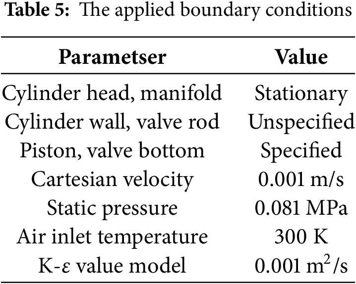
Fig. 6 shows the profiles of the combustion chamber pressure change range with a crank angle for all fuel samples prepared at a load of 200 Nm. It can be observed that the burning rate increases due to the addition of nanomaterials resulting from the high Cetane number and short ignition delay, and this is due to the higher surface area of the nano additives and their catalytic effect. Developments in the combustion pattern after adding the nanomaterial were represented by an increase in peak cylinder pressure. Fig. 7 displays the most important changes in cylinder pressure (Pcy) during the combustion process with the crank angle for all fuel samples tested at a load of 200 Nm, where we notice an increase in Pcy for the nano fuel mixture compared to diesel fuel due to the increase in fuel consumption in the combustion process, while the Pcy with increasing proportion of nanoparticles in the biodiesel blend for fuel tested samples B20A50, B20A100, and B20A150.
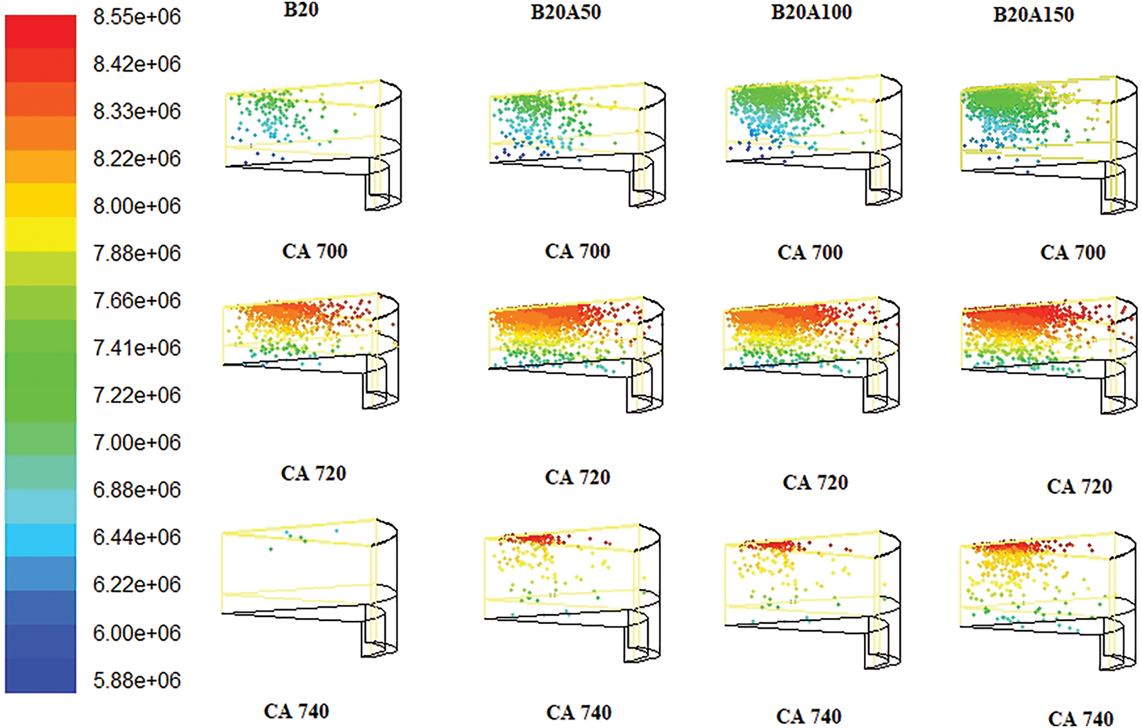
Figure 6: Contours of cylinder pressure variation with crank angle of all tested fuels at load 200 Nm
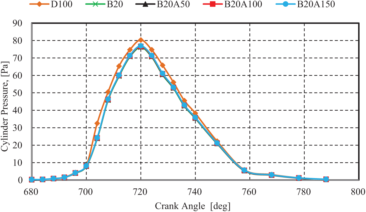
Figure 7: Variation of cylinder pressure with a crank angle of all tested fuels at load 200 Nm
Fig. 8 displays the peak cylinder pressure under the influence of nano-particles at different load conditions. Peak cylinder pressure of B20A50 at 50 ppm appeared the higher value from the Biodiesel blend at different loads. Also, this behavior repeated for B20A100 and B20A150 at 100 and 150 ppm. The increases in the peak cylinder pressures for B20A50, B20A100, and B20A150 about D80B20 were 3%, 5%, and 8%, respectively, at load 200 Nm. These results are consistent with the results of several researchers in [9,22,23].
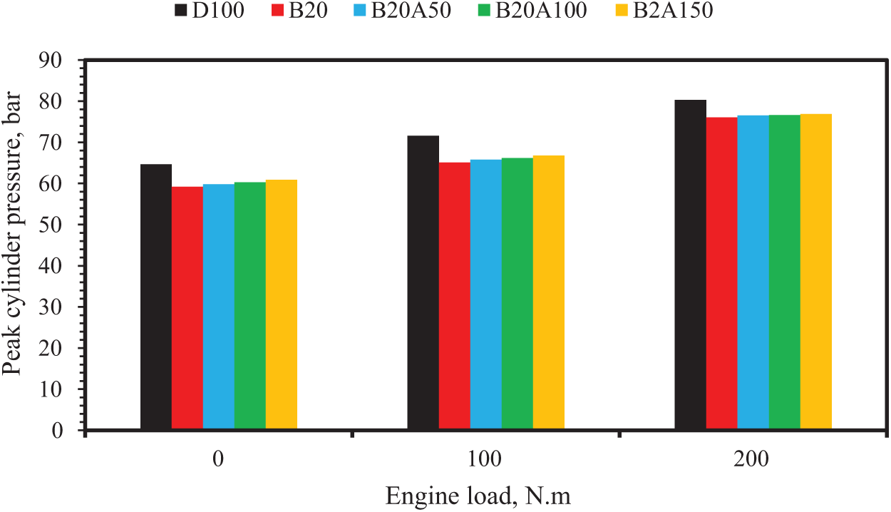
Figure 8: Peak cylinder pressure of diesel and biodiesel blend with nano-additives at different loads
Fig. 9 displays the contours of temperature distribution for Diesel and Biodiesel blends with nano-material (Al2O3) at 150 ppm B20A150 with crank angle from combustion modes in numerical procedures. At state engine load 200 Nm and crank angle 720°, the combustion temperature reached up to 1164 K inside the cylinder. While uniform distributions of combustion temperature were recorded inside the cylinder for all crank angles within the combustion cycle; it is clear from the figure that the best combustion was achieved by adding 150 ppm nanomaterials to the fuel sample B20A150. The maximum temperature recorded from this combustion was about 1188 K. After comparing both pure diesel and the rest of the fuel samples, no high difference appeared in temperature. Fig. 10 presents the maximum temperature of all fuel samples at different loads. Through the simulation was found that the maximum temperature for B20 was higher than D100; this was due to higher hydrocarbon values of B20. While nano additives caused a decrease in temperatures in the combustion of biofuels.
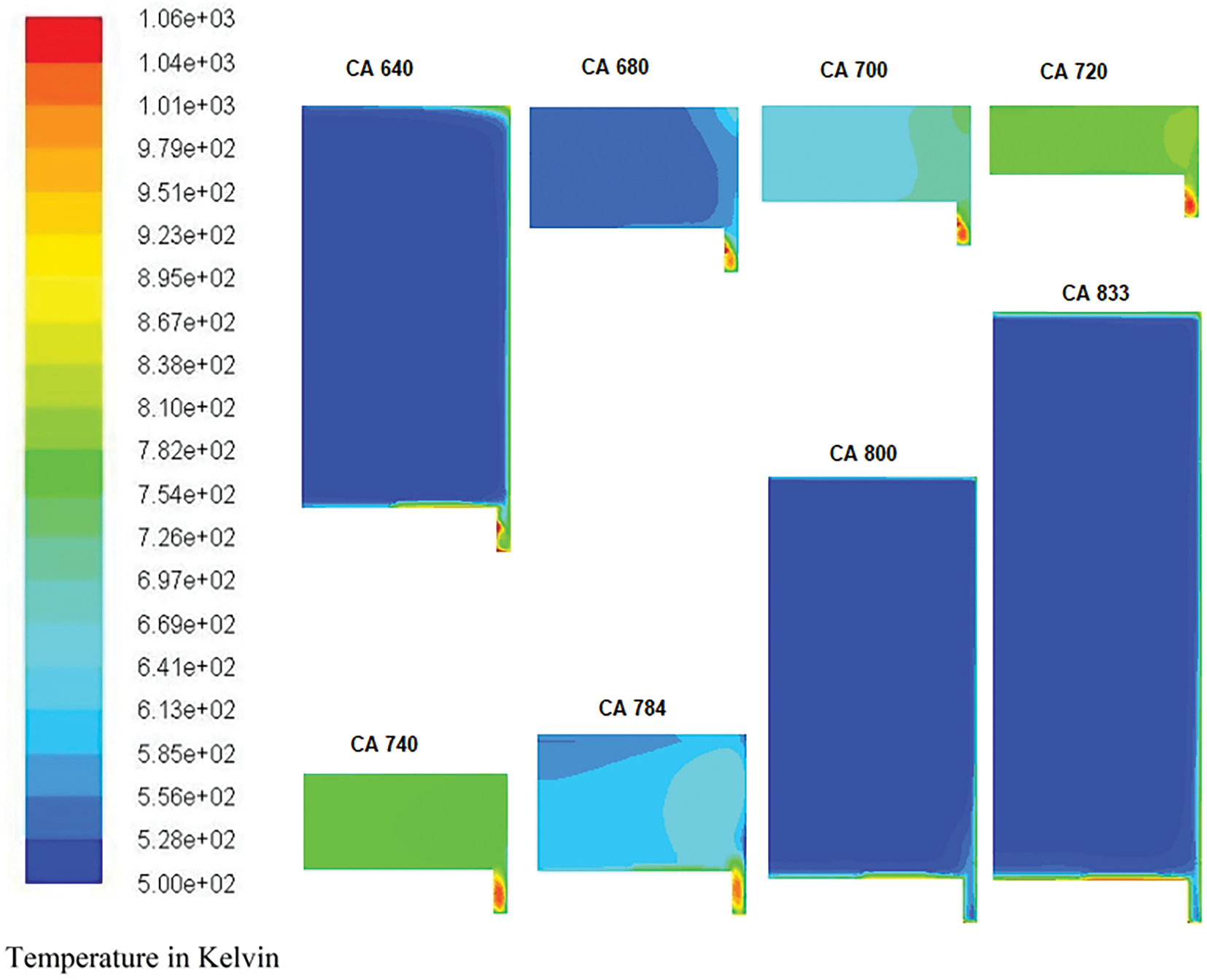
Figure 9: Contours of cylinder temperature variation with crank angle of B20A150 at load 200 Nm
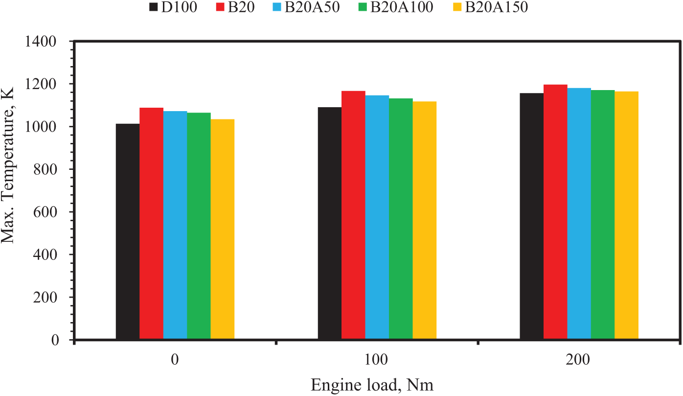
Figure 10: Max. The temperature of diesel and biodiesel blends with nano-additives at different loads
Fig. 11 shows the contours of burn charge velocity distribution during the combustion cycle using B20A150. The profiles describe that low values of charge velocities were recorded in the center portion of the cylinder compared to the near piston edge region. The main cause of this behavior was lower swirl value during compression stroke and combustion. Generally, the data of recorded swirl value is higher through the intake stroke due to suction operation, while it’s reduced during compression and combustion strokes. However, the swirl enhancement occurs after fuel charge injection by fuel diffusion. Generally, a swirl is defined as an organized charge rotation around the cylinder’s axis. The swirl grows based on initial angular momentum through the intake flow into the cylinder. The air motion inside the cylinder affects the combustion process. Increasing the swirl density causes acceleration of the mixing process due to increased air velocity and provides conditions for a flammable mixture at the ignition point.
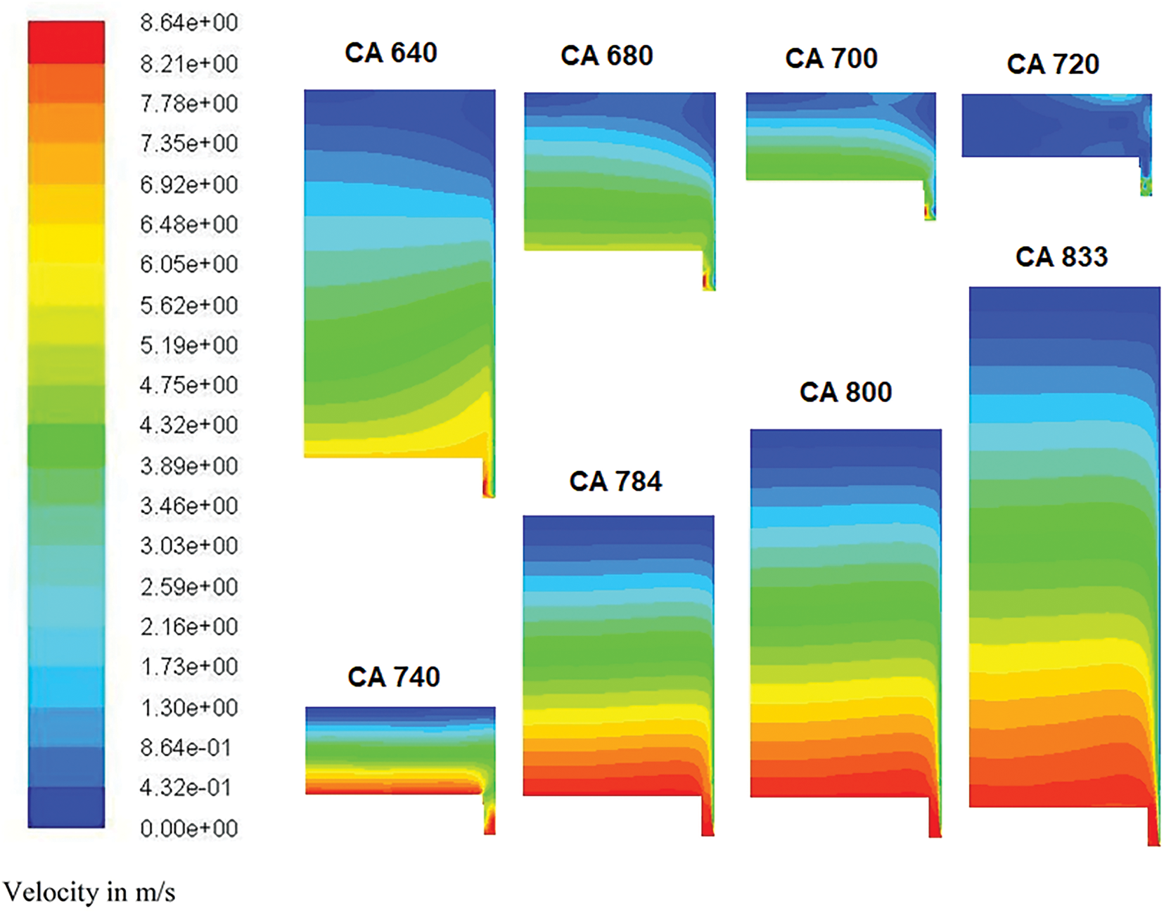
Figure 11: Contours of velocity distribution at different crank angles of B20A150 at load 200 Nm
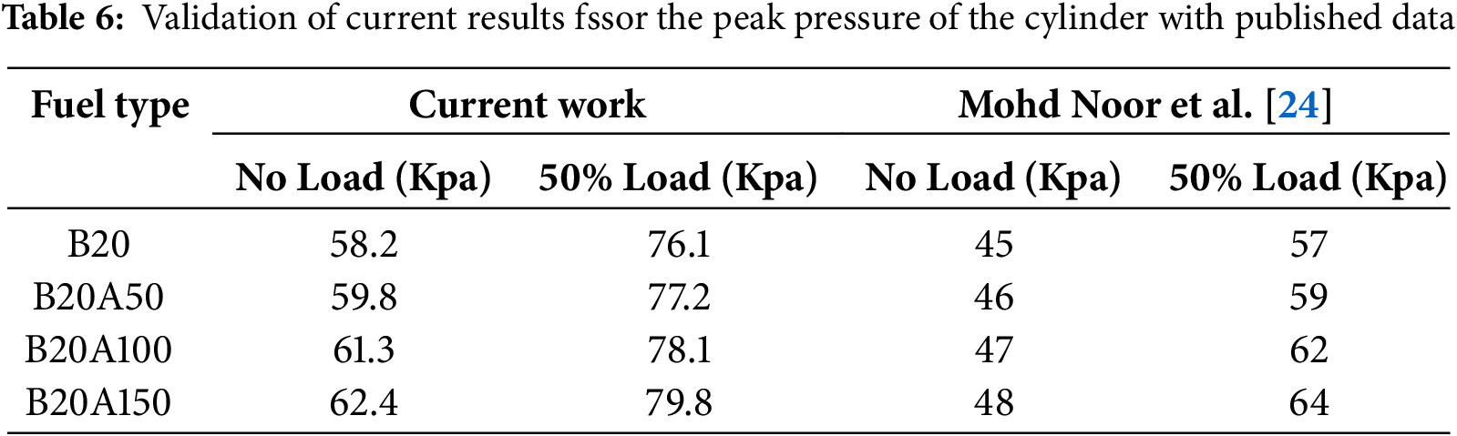
Fig. 12 compares numerical and experimental results of peak pressure with engine load for B20 and B20A150 blends for the base engine. The peak pressure depends on the fuel taking part in the combustion phase, which is based on the delay period and the spray envelopes of the injected fuel. The difference percentages of peak pressure for the no0load engine with B20 and B20A150 were 7.3% and 4.2%, respectively, whereas for the full load were 9.1% and 6.7% for B20 and B20A150. Table 6 illustrates the validation of peak cylinder pressure values of the B20 and nano fuels utilized in this study at various engine loads with results obtained by Mohd Noor et al. [24].
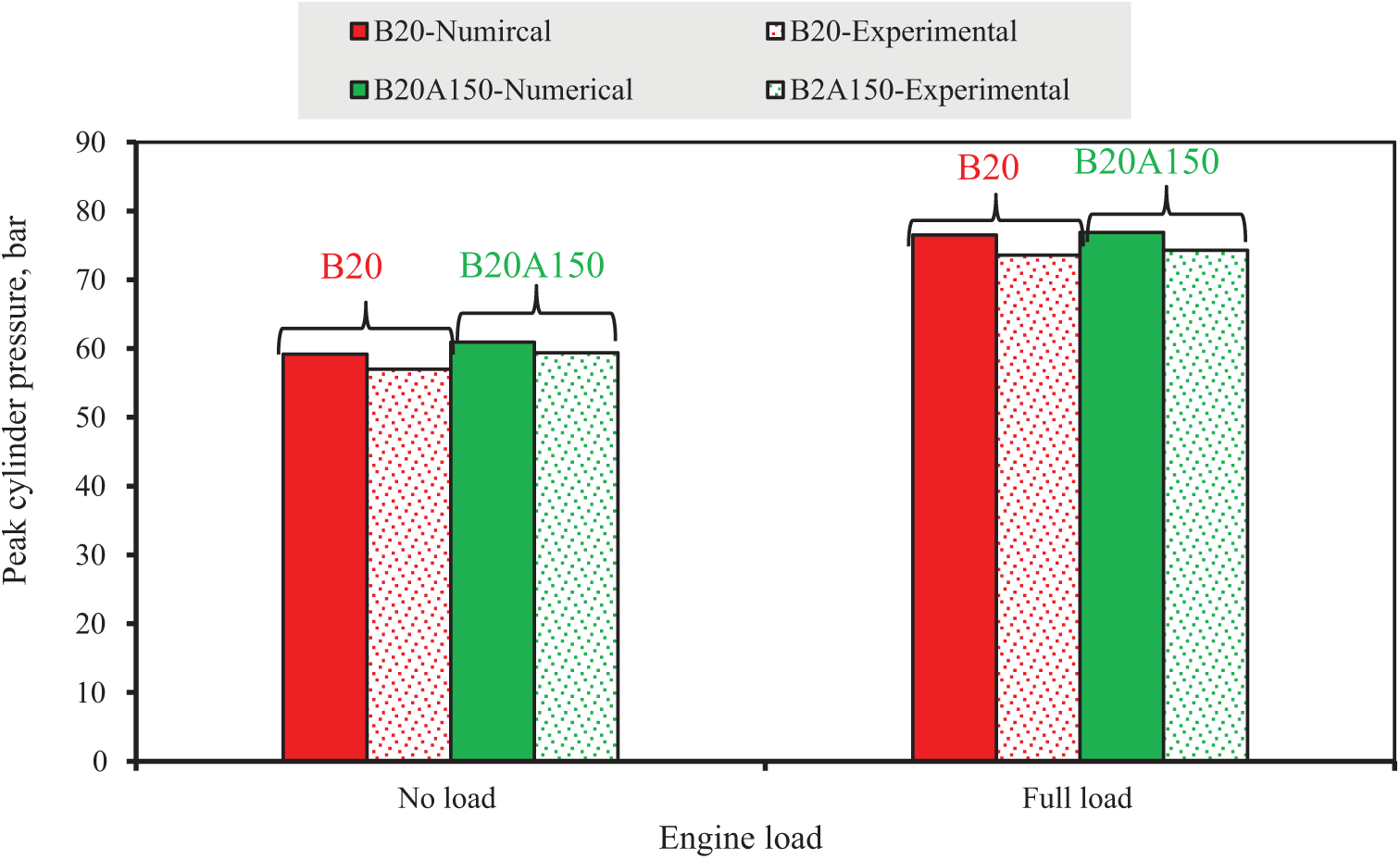
Figure 12: The comparison of numerical and experimental results of peak pressure with engine load for B20 and B20A150 blends
The present numerical analysis aims to verify the use of diesel and biodiesel mixture as a diesel engine fuel as an alternative fuel, especially with its enhancement by adding nanoparticles. Several models of mixtures of Al2O3 nanoparticles were examined numerically to clarify combustion behavior and indicate engine performance to evaluate the effect of mixing Al2O3 nanoparticles with biofuel on engine performance characteristics. An axisymmetric CFD analysis was carried out for neat diesel, and Biodiesel blends with Al2O3 nanoparticles for diesel engines. The simulation analysis included five samples of diesel and additives. The following are the major conclusions that can be drawn from the study’s findings:
• The increases in the peak cylinder pressures for B20A50, B20A100 and B20A150 are 3%, 5% and 8%, respectively, compared to B20 at load 200 Nm.
• Through the simulation, it was found that the maximum temperature for biodiesel blends diesel was higher than pure diesel; this was due to higher hydrocarbon values of B20. While nano-additives caused a decrease in temperatures in the combustion of biofuels.
• Finally, it indicates that lower velocity was found at the center portion of the working volume than near the walls. Swirl value is higher during intake stroke due to sucking operation, and then it gets reduced during compression and combustion processes.
Further investigations using different biofuel types with nano additives and amounts of surfactant added to the diesel fuel blends, effect analysis of fuel injection pressure, and effect heat of vaporization are recommended.
Acknowledgement: The authors thank many researchers at Karabuk University, Karabuk, Turkey, for their meaningful discussion.
Funding Statement: The authors received no specific funding for this study.
Author Contributions: The authors confirm contribution to the paper as follows: study conception and design: Ameer H. Hamzah, Abdulrazzak Akroot; data collection: Hasanain A. Abdul Wahhab; analysis and interpretation of results: Hasanain A. Abdul Wahhab, Abdulrazzak Akroot; draft manuscript preparation: Ameer H. Hamzah, Hasanain A. Abdul Wahhab. All authors reviewed the results and approved the final version of the manuscript.
Availability of Data and Materials: The datasets are available to the corresponding author upon reasonable request.
Ethics Approval: Not applicable.
Conflicts of Interest: The authors declare no conflicts of interest to report regarding the present study.
Nomenclature
| CA | Crank angle, deg ss |
| St | Turbulent flame speed, cm/s |
| D | The spark location |
| rt | Length scale of cell |
| lt | Length scale for Turbulence |
| ro | The initial radius of the spark, mm |
| Pcy | Cylinder Pressure, bar |
| Tf | Flame temperaturess, °C |
| Greek Symbols | |
| Burned fluid density, kg/m3 | |
| Abbreviations | |
| IC | Internal comsbustion |
| IVC | Inlet valve closed |
| EVO | Exhaust valve open |
| CFD | Computational fluid dynamics |
| BSFC | Brake-specific fuel consumption |
| BC | Boundary conditions |
| RMB | Review Medical Board |
References
1. Fadil A, Mashkour MA, Abdul Wahhab HA. Investment of blending biofuels and nanoparticles with conventional diesel fuel to improve combustion process—a review. In: Emamian SS, Awang M, Razak JA, editors. Advances in material science and engineering. Berlin/Heidelberg, Germany: Springer; 2023. p. 95–107. doi:10.1007/978-981-19-3307-3_9. [Google Scholar] [CrossRef]
2. Vohra G, Kumar V, Singh H, Sham R. Effect of biodiesel on the performance and emission characteristics of diesel engines. Int J Eng Res Technol. 2020;13(6):1076–94. doi:10.37624/IJERT/13.6.2020.1076-1094. [Google Scholar] [CrossRef]
3. Jumaa H, Mashkour MA. Humidification effect on the performance and emissions of (DI) diesel engine running on diesel fuel with biodiesel blended nano additives. Eng Technol J. 2021;39(5):790–803. doi:10.30684/etj.v39i5A.1935. [Google Scholar] [CrossRef]
4. Fayad MA, Al-Ogaidi BR, Abood MK, Al-Salihi HA. Influence of postinjection strategies and CeO2 nanoparticles additives in the C30D blends and diesel on engine performance, NOx emissions, and PM characteristics in diesel engine. Part Sci Technol. 2021;40(7):824–37. doi:10.1080/02726351.2021.2017088. [Google Scholar] [CrossRef]
5. HShariat Panahi HK, Dehhaghi M, Orooji Y, Shahbeik H, Mahian O, Karimi-Maleh H, et al. Applications of nanotechnology in biodiesel combustion and post-combustion stages. Renew Sustain Energy Rev. 2023;182(7):113414. doi:10.1016/j.rser.2023.113414. [Google Scholar] [CrossRef]
6. Sadeq AM. Combustion advancements: from molecules to future challenges. Berlin/Heidelberg, Germany: Springer; 2023. doi:10.13980/RG.2.2.33942.88991. [Google Scholar] [CrossRef]
7. Idris M, Husin I, Hermawan I, Novalia U, Batubara RD, Pambudi NA, et al. Engine performance using blended fuels of biodiesel and eco diesel. Energy Eng J. 2023;120(1):107–23. doi:10.32604/ee.2023.019203. [Google Scholar] [CrossRef]
8. Devarajan Y, Nagappan B, Subbiah G. A comprehensive study on emission and performance characteristics of a diesel engine fueled with nanoparticle-blended biodiesel. Environ Sci Pollut Res. 2019;26(11):10662–72. doi:10.1007/s11356-019-04446-1. [Google Scholar] [PubMed] [CrossRef]
9. Soudagar MEM, Nik-Ghazali NN, Kalam MA, Badruddin IA, Banapurmath NR, Ali MAB, et al. An investigation on the influence of aluminium oxide nano-additive and honge oil methyl ester on engine performance, combustion, and emission characteristics. Renew Energy. 2020;146(4):2291–307. doi:10.1016/j.renene.2019.08.025. [Google Scholar] [CrossRef]
10. Fadil A, Mashkour MA, Abdul Wahhab HA. Influence of alumina nanoparticles additives into biofuel (water hyacinth)-diesel mixture on diesel engine performance and emissions. Mater Und Werkst. 2023;54(9):1107–13. doi:10.1002/mawe.202100365. [Google Scholar] [CrossRef]
11. Abdul Wahhab HA, Mashkour MA, Madodi S. Investigation of water-diesel emulsion characteristics using optical technique. J Appl Fluid Mech. 2020;13(1):349–55. doi:10.29252/jafm.13.01.30133. [Google Scholar] [CrossRef]
12. Venu H, Raju VD, Subramani L. Combined effect of influence of nano additives, combustion chamber geometry and injection timing in a DI diesel engine fuelled with ternary (diesel-biodiesel-ethanol) blends. Energy. 2019;174(1):386–406. doi:10.1016/j.energy.2019.02.163. [Google Scholar] [CrossRef]
13. YOokawara SA, Ahmed MA, El-Khouly MA, Elmehasseb IM, El-Shafai NM, Elwardany AE. Investigating the engine performance, emissions and soot characteristics of CI engine fueled with diesel fuel loaded with graphene oxide-titanium dioxide nanocomposites. Fuel. 2020;269(4):117436. doi:10.1016/j.fuel.2020.117436. [Google Scholar] [CrossRef]
14. Zhao Z, Miao X, Chen X, Zheng J, Di Y, Bao Z, et al. Simulation study of diesel spray tilt angle and ammonia energy ratio effect on ammonia-diesel dual-fuel engine performance. Energy Eng J. 2024;121(9):2603–20. doi:10.32604/ee.2024.051237. [Google Scholar] [CrossRef]
15. Sujaykumar G, Ravikumar R, Mutalikdesai S, Pujar B, Baddi V, Siddapur D, et al. Comparative study of waste cooking oil and cashew nut shell oil bio fuel blends with diesel. Energy Power. 2017;7(3):65–9. doi:10.5923/j.ep.20170703.02. [Google Scholar] [CrossRef]
16. Annamalai M, Dhinesh B, Nanthagopal K, Sivarama Krishnan P, Ramesh Lalvani JIJ, Parthasarathy M, et al. An assessment on performance, combustion and emission behavior of a diesel engine powered by ceria nanoparticle blended emulsified biofuel. Energy Convers Manag. 2016;132(2):372–80. doi:10.1016/j.enconman.2016.06.062. [Google Scholar] [CrossRef]
17. Mitchell BJ, Zare A, Bodisco TA, Nabi MN, Hossain FM, Ristovski ZD, et al. Engine blow-by with oxygenated fuels: a comparative study into cold and hot start operation. Energy. 2017;140(1):612–24. doi:10.1016/j.energy.2017.08.115. [Google Scholar] [CrossRef]
18. Hossain FM, Nurun Nabi M, Rainey TJ, Bodisco T, Mostafizur Rahman M, Suara K, et al. Investigation of microalgae HTL fuel effects on diesel engine performance and exhaust emissions using surrogate fuels. Energy Convers Manag. 2017;152:186–200. doi:10.1016/j.enconman.2017.09.016. [Google Scholar] [CrossRef]
19. Hosseinzadeh-Bandbafha H, Tabatabaei M, Aghbashlo M, Khanali M, Khalife E, Shojaei TR, et al. Consolidating emission indices of a diesel engine powered by carbon nanoparticle-doped diesel/biodiesel emulsion fuels using life cycle assessment framework. Fuel. 2020;267:117296. doi:10.1016/j.fuel.2020.117296. [Google Scholar] [CrossRef]
20. Sunil S, Prasad BC, Kakkeri S. Studies on titanium oxide nanoparticles as fuel additive for improving performance and combustion parameters of CI engine fueled with biodiesel blends. Mater Today Proc. 2021;44(1):489–99. doi:10.1016/j.matpr.2020.10.200. [Google Scholar] [CrossRef]
21. Rangabashiam JVD, Rameshbabu A. Emission, performance, and combustion study on nanoparticle-biodiesel fueled diesel engine. Energy Sources Part A Recovery Util Environ Eff. 2019;45(3):8396–407. doi:10.1080/15567036.2019.1677821. [Google Scholar] [CrossRef]
22. Gad MS, Jayaraj S. A comparative study on the effect of nano-additives on the performance and emissions of a diesel engine run on Jatropha biodiesel. Fuel. 2020;267(1):117168. doi:10.1016/j.fuel.2020.117168. [Google Scholar] [CrossRef]
23. Chen AF, Adzmi MA, Adam A, Othman MF, Kamaruzzaman MK, Mrwan AG. Combustion characteristics, engine performances and emissions of a diesel engine using nanoparticle-diesel fuel blends with aluminium oxide, carbon nanotubes and silicon oxide. Energy Convers Manag. 2018;171(2):461–77. doi:10.1016/j.enconman.2018.06.004. [Google Scholar] [CrossRef]
24. Mohd Noor CW, Ismail AA, Nur Fhatihah A, Fadhli Ahmad M, Nor Khasbi Jarkoni M, Briggs HG. Assessing the effect of aluminium oxide nanoparticle additives on biodiesel combustion in marine diesel engines. IOP Conf Ser Earth Environ Sci. 2024;1372(1):012029. doi:10.1088/1755-1315/1372/1/012029. [Google Scholar] [CrossRef]
Cite This Article
 Copyright © 2025 The Author(s). Published by Tech Science Press.
This work is licensed under a Creative Commons Attribution 4.0 International License , which permits unrestricted use, distribution, and reproduction in any medium, provided the original work is properly cited.
 Downloads
 Citation Tools