
 Submit a Paper
 Propose a Special lssue
 Open Access
ARTICLE
Determining the Energy Potential of Deep Borehole Heat Exchangers in Croatia and Economic Analysis of Oil & Gas Well Revitalization
Department of Petroleum and Gas Engineering and Energy, Faculty of Mining, Geology and Petroleum Engineering, University of Zagreb, Zagreb, 10000, Croatia
* Corresponding Author: Tomislav Kurevija. Email:
(This article belongs to the Special Issue: Selected Papers from the SDEWES 2024 Conference on Sustainable Development of Energy, Water and Environment Systems)
Energy Engineering 2026, 123(1), 1 https://doi.org/10.32604/ee.2025.067067
Received 24 April 2025; Accepted 12 November 2025; Issue published 27 December 2025
 View Full Text
 Download PDF
Abstract
The increased interest in geothermal energy is evident, along with the exploitation of traditional hydrothermal systems, in the growing research and projects developing around the reuse of already-drilled oil, gas, and exploration wells. The Republic of Croatia has around 4000 wells, however, due to a long period since most of these wells were drilled and completed, there is uncertainty about how many are available for retrofitting as deep-borehole heat exchangers. Nevertheless, as hydrocarbon production decreases, it is expected that the number of wells available for the revitalization and exploitation of geothermal energy will increase. The revitalization of wells via deep-borehole heat exchangers involves installing a coaxial heat exchanger and circulating the working fluid in a closed system, during which heat is transferred from the surrounding rock medium to the circulating fluid. Since drilled wells are not of uniform depth and are located in areas with different thermal rock properties and geothermal gradients, an analysis was conducted to determine available thermal energy as a function of well depth, geothermal gradient, and circulating fluid flow rate. Additionally, an economic analysis was performed to determine the benefits of retrofitting existing assets, such as drilled wells, compared to drilling new wells to obtain the same amount of thermal energy.Keywords
Given the Republic of Croatia’s long history of hydrocarbon production, the high water cut, and the existing mature hydrocarbon fields, a significant number of wells are expected to be liquidated or temporarily abandoned over the next decade. With the inevitable decrease in hydrocarbon production, more wells are expected to fall within the abandonment category. As an alternative to the expensive abandonment process, deep wells can be revitalized and used as deep borehole heat exchangers (DBHEs) to exploit heat energy [1]. Deep coaxial borehole heat exchangers (DCBHE) consist of an outer (casing) and an inner pipe (tubing) through which water as a working fluid circulates (pipe-in-pipe configuration), either in CXA flow direction with annular inlet, or CXC flow direction where inlet is central pipe, i.e., tubing. The working fluid circulation is achieved using a common industrial-type circulation pump. Heat transfer from the source rock to the circulating fluid occurs through the casing (outer pipe), regardless of the set flow direction.
Previous research shows that interest in the conversion and revitalization of abandoned wells has risen over the last decade. Using revitalized wells is recognized as a potential source of geothermal energy, with several advantages of such a conversion. The most significant advantage is the reduction in capital costs (CAPEX) for drilling a new geothermal well, where the highest cost is drilling itself. One study showed that well revitalization could reduce capital costs by up to 50% compared to drilling a new geothermal well [2]. Additionally, high liquidation and abandonment costs for hydrocarbon wells can be offset by reusing existing wells through technological solutions that prolong their lifespan [3,4]. This means lower well abandonment costs for oil & gas companies, allowing continued well utilization with no risk of environmental pollution [5], and increasing the share of geothermal energy in the energy balance. Although the energy potential of well reuse via a deep coaxial heat exchanger has been theoretically proven, there are only a few operational examples worldwide. The best-known example is located in the town of Weggis, Switzerland. Kohl et al. [6] presented results of measurements during operation of a deep coaxial heat exchanger (2.3 km) in which the dry well was revitalized and put into operation in 1994. Measurements were carried out over the three years of the DCBHE’s operation, and analysis of inlet and outlet fluid temperatures indicated that the deep exchanger was underused. The conclusion was based on the mean temperature of the working fluid returning from the system to the well, which was around 40°C. The results of the numerical analysis for different working-fluid mass flows showed that the system can provide more thermal energy than it consumes. In local residential and commercial buildings, around 20 W/m was used, while calculations showed the system can support up to 85 W/m. Around the same time, another well in Switzerland, in the town of Weissbad, was also revitalized by using a deep heat exchanger with a depth of 1.2 km [7]. The operation of this revitalized well was continuously monitored for two years [7]. The measurement results showed that the well produced less thermal energy than predicted by the numerical simulations, indicating that incomplete cementation of the exchanger’s outer column reduced overall heat transfer. In addition to the revitalized wells in Weggis and Weissbad, another well in Switzerland was revitalized, in the Zurich area, with a depth of 2.7 km [8]. In Aachen (Germany) in 2004, a well was drilled in which a deep heat exchanger was installed. The well is located next to the University of Aachen and was intended to heat a newly built university facility. Analysis of data collected during construction and subsequent simulations showed that the exchanger would provide sufficient energy for heating [9]. However, due to the high outlet fluid temperature, it was not possible to achieve cooling during the summer with the existing absorption system. In addition, the potential was not achievable given the substantial financial investment required to insulate the tubing, and further development of the project was abandoned. Another example of a working DCBHE system is in China. System testing has shown that, with heat pumps, a coefficient of performance (COP) of 6.4 is achieved at 286 kWt of installed heat power [10].
Research on deep well heat exchangers has shown the potential to utilize thermal energy with various working fluids, with water as the cheapest option [11]. The advantage of water as a working fluid is its favorable, easily accessible properties, as well as the fact that, in the event of a leak, there is no risk of contaminating groundwater, soil, or rocks. A number of research papers have been published on estimating the available thermal energy using DBHE, based on either numerical or analytical models of heat transfer from the rock to the circulating fluid. Kujawa et al. [12] presented a numerical model of the thermal energy transfer. The calculation was performed for different flow rates and three cases of tubing insulation: no insulation, partial insulation, and full-length insulation. The highest available thermal energy was obtained for the case in which the tubing was insulated along its entire length, due to the reduced effect of heat short-circuiting between the warmer and colder working fluid [1,12]. Besides classic analytical methods for determining the heat transfer rate in DBHE, which are based on solving the partial differential equation of heat diffusion, numerous papers have proposed numerical methods [12–15]. Alimonti and Soldo [13] did a comprehensive study of proposed heat transfer models. The study also gathered data on available thermal and electric power from available research. The range for thermal power was 0.15–2.5 MWt, and for electric power, 0.25–364 MWe. This shows how adequate revitalization of abandoned oil and gas wells can contribute to a broader geothermal energy base in the energy mix. The use of such low-temperature systems is suitable for direct heating of residential and commercial buildings, heating domestic hot water, balneology, agriculture, seawater desalination [16], etc. Research into DCBHE operations showed that the distance between two DCBHEs should be at least 100 m to avoid interference [17]. Also, the research recommended considering heat pump characteristics when determining injection rates to ensure an optimal system design. Li et al. [18] investigated increasing heat extraction rates by implementing a finned inner pipe in the DCBHE and found that heat extraction increased with increasing inlet flow rate. The study found that fin spacing and fin height improve the Nusselt number over a range, but fin thickness has a negligible effect on fluid flow and heat transfer. Li et al. [19] considered stratification of soil and rock layers and their respective thermal properties when establishing a heat-extraction model for the DCBHE. The study showed that fluid flow rate and pipe diameter significantly influenced the extraction rate. A new study [20] on the operation of medium-deep U-type BHEs with various circulating fluids (water, ammonia, supercritical CO2, etc.) provided recommendations for selecting the appropriate fluid type based on operational conditions.
With only a few operational DBHE systems, the planned number worldwide is increasing. A project in Xi’an, China, is set to have 91 DBHE wells, each of 2500 m depth. The field testing and subsequent modeling of one such DBHE during 2020–2021 showed an average of 300 kWt of extraction is possible [21]. The company Minig Support Ltd. implemented the WeHEAT System in Kiskunhalas, Hungary in 2021, where a dry hydrocarbon well was converted to a DBHE system for direct application, with up to 500 kW of thermal power [22]. Further implementation and development of such projects are expected in the future, given the high number of hydrocarbon wells in Hungary. The use of the DBHE is also considered for storage applications, through borehole thermal energy systems (BTES) applied in medium depths. The PUSH-IT project is developing the only medium-deep BTES pilots in the world. At the Darmstadt pilot site, three 750 m wells were drilled during the SKEWS project [23], while their long-term testing is monitored within the PUSH-IT project [24]. The second site is at Litomeřice, Czechia, where hydrogeological wells were drilled, while the 550 m pilot is awaiting the continuation of drilling, which was halted due to aquifer layer collapse [25]. The Eavor company is also developing deep heat exchanger systems using multilateral horizontal wells connected through two vertical wells [26]. The Derek Riddell Eavor-Lite™ Demonstration Facility demonstrated the feasibility of multilateral legs at 2.4 km depth with negligible leaks [27], while the European site Eavor-Loop™ Geretsried aims to supply thermal energy for district heating and electricity [28]. Outside of heating applications, a project in California, USA, conducted an experimental demonstration of the power production using supercritical CO2 [29]. Testing and modelling showed thatCO2, in full-scale application with a 1000 m well, supercritical CO2 can deliver over 100 kW of electricity. In Slovenia, in the village of Čentiba, an abandoned well Pg-8, was revitalized and is being tested as an innovative pilot geothermal power plant [30]. The plant has a capacity of 50 kWe, and the technology uses a geothermal gravity heat pipe. The selected DBHE sites, as well as newly developed technologies in the world, are shown in Table 1.

Since the mid-20th century, around 4000 exploration, production, injection, and monitoring wells have been drilled in Croatia, with about 2/3 already abandoned, and more are expected to be abandoned in the near future. Of those 4000 wells, around 900 are designated as active and used for production, injection, or monitoring. Hydrocarbon production in Croatia has generally declined over the last decade, due to the majority of the fields being mature. However, recent confirmations of new gas reserves could temporarily halt the decline in hydrocarbon production. In 2023, oil production was 561,000 m3, condensate production was 47,200 m3, and 691.3 million m3 of natural gas was produced. Wells nearing the end of their lifespans must undergo abandonment, a capital-intensive process for oil and gas companies. Instead of abandoning these wells, some of them could become future assets through revitalization to harness available geothermal energy. Not all wells are suitable for revitalization, primarily because most prospecting wells have been abandoned for a long time. However, newer wells (this period stretches from the 80s to the present day) that need to be abandoned certainly present an opportunity to repurpose them as geothermal wells. This research analyzed the available thermal energy potential by implementing the DCBHE revitalization option, using two typical end-user load types: constant and variable. Constant loads require the same amount of thermal energy throughout the year from DCBHE operation (e.g., industry or dry processing plants). Variable loads depend on current climate conditions and follow thermal energy demand during the heating season. When it comes to the technical options of heating systems, there are also two possibilities—direct utilization of heat (borehole heat exchanger > plate heat exchanger > user) and heat pump application (borehole heat exchanger > plate heat exchanger > heat pump > user). The results of constant and variable modelling (with both technical solutions) show very good potential in available heating energy when using a DCBHE.
The first assessment of the available thermal energy by varying well depth, fluid flow, and geothermal gradient is carried out through the implementation of DCBHE in the continental part of the Republic of Croatia, where geothermal potential exists. This assessment can serve as a useful validation point when evaluating the potential of a typical deep well when revitalized as a deep coaxial borehole heat exchanger (DBHE) system. With numerous wells identified as good candidates for such a conversion, this paper conducts a prefeasibility assessment of the available thermal energy potential, which can then be translated into specific wells considered for revitalization. The analysis of fluid flow and pressure drop in the deep BHE identified limitations in real systems that need to be addressed in the design. The utilization factor (the so-called seasonal performance factor - SPF) of deep BHE needs to be determined to indicate the ratio of the electricity required for the operation of the circulation pump vs. the available thermal energy from the DCBHE system. The analysis showed that as SPF increases, savings increase compared to a classic energy source, such as natural gas.
The mathematical model describing conductive heat transfer through a porous medium was first formulated by Fourier [34]. This is known as the Fourier law or differential equation of heat diffusion. There are two main methods for describing conductive heat transfer: analytical and numerical. Both methods require initial and boundary conditions to solve the differential heat-diffusion equation.
Analytical methods are used to solve the heat diffusion equation by considering either a line source or a cylindrical source model. The line-source models assume that the borehole heat exchanger is located in an infinite, isotropic, homogeneous porous medium of constant thickness. Calculations were performed in the GHX Toolbox, developed by Chiasson [35], which is based on Eskilson’s line-source heat-transfer model and includes borehole thermal resistance calculations for the BHE configuration. Two main line source models are infinite and finite line source models (ILS and FLS), with the latter used in the GHX Toolbox software.
Finite Line Source Model (FLS)
The FLS model solves the partial differential heat diffusion equation with vertical component included, i.e., the true length of the heat exchanger is observed. This model is commonly used when the boundary conditions for using the infinite line source (ILS) model are not achieved (short time period of calculations, shallow boreholes). FLS, unlike ILS, provides an accurate simulation of long-term performance in deep boreholes by accounting for axial conduction and boundary conditions at the top and bottom. ILS is a simpler, analytical function for simpler systems that ignores axial heat conduction and governs only radial heat transfer. Because it is used for long-term borehole operation (over a month/year), it can underestimate the temperature drop due to subcooling (i.e., overestimate performance). Since the top of the borehole is at much lower temperatures compared to mid-to bottom depths (especially in higher geothermal gradient locations), ILS becomes less accurate due to end effects becoming much more relevant. The FLS gives a much more accurate result than ILS when designing a real well, and compared to numerical simulation, it yields a 10%–15% difference in SPF prediction. For the initial estimation of possible DBHE capacity, the FLS method is deemed suitable. The initial conditions to solve partial heat diffusion equations are given as:
Based on initial and boundary conditions, Claesson and Eskilson [36] gave solution to calculate temperature at the borehole wall, using the so-called g-function:
where g-function is defined as:
And ts is time at which steady-state heat transfer is achieved:
The average temperature of the circulating fluid, for a constant unit heat demand and accounting for thermal borehole resistance, is then given as:
To determine the fluid temperature within the borehole heat exchanger, thermal borehole resistance, Rb, has to be determined. Thermal borehole resistance depends on the thermodynamic properties of the well cement, the pipe materials, the working fluid properties, and the fluid flow regime. The thermal resistance of heat transfer from the source rock to the coaxial system is analogous to skin effect in petroleum engineering [37]. This nondimensional value represents the damage in the near-borehole zone, leading to a drop in the working fluid’s temperature. For the borehole heat exchanger, the temperature drop is defined as:
where skin coefficient s is defined as [5]:
For the constant heating load, the time-dependent temperature change can be obtained from Eq. (7). However, constant heating loads throughout the working period are rare in real systems, although they are preferable. A more realistic demand scenario involves variable heating loads that change with climate conditions on a yearly, monthly, daily, and hourly basis. The temperature profile of the circulating fluid is therefore dependent on the time-varying heating load. The principle of superposition is used to describe the temperature profile for a variable heating load. Superposition is based on the sum of individual temperature profiles, each of which depends on the applied heating load. Chiasson [35] described the principle of superposition for several different heating loads. It is based on superimposing each heat load onto the previous one, with the first heating load applied to the entire time interval, i.e.,
To determine the average circulating fluid temperature in the DBHE, thermal borehole resistance must be accounted for. The overall heat transfer coefficient, which is a function of overall thermal resistance, determines the efficiency of the heat transfer from the source rock to the circulating fluid in the coaxial borehole deep exchanger. In borehole heat exchangers, the overall thermal resistance includes both conductive and convective components. The conductive component relates to the pipe, cement, and ground heat transfer resistances. The convective component is related to the convective resistance caused by fluid flow. Since coaxial borehole heat exchangers show preferable hydraulic conditions (lower pressure drop values) when compared to the classic design of U-loop, the coaxial design was chosen in the case of revitalization of oil & gas wells. Coaxial heat exchangers use a pipe-in-pipe design, with fluid circulating through the inner pipe (the inner channel of flow) and the annulus (the outer channel of flow). In regard to the geometrical design, borehole thermal resistance, when using coaxial heat exchangers, can be divided into two main parts:
a. resistance to heat transfer between inner and outer flow channel
b. resistance between outer flow channel and outer pipe.
The thermal resistance between the inner and outer flow channels is comprised of: resistance due to convection of circulating fluid in both flow channels, thermal resistance due to conductive heat transfer in the inner pipe, and thermal resistance due to convection between the outer wall of the inner pipe and circulating fluid in the outer flow channel. The thermal resistance between the outer flow channel and outer pipe is comprised of: thermal resistance due to convection of circulating fluid in the outer flow channel and inner wall of the outer pipe, resistance due to conductive heat transfer in the outer pipe, and thermal resistance due to conductive heat transfer in the cement layer, which connects the outer pipe and source rock. Effective borehole thermal resistance is then [38]:
where
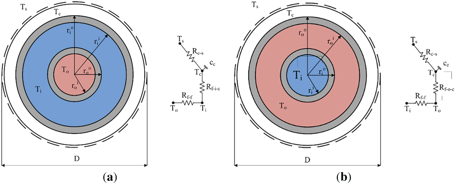
Figure 1: (a) CXA fluid flow configuration; (b) CXC fluid flow configuration [39]
3 Technical and Thermogeological Settings
3.1 Well Revitalization Process
Liquidated wells are wells in which several cement plugs are set at several different depths to prevent the occurrence of formation fluid and communication with the surface or existing shallow aquifers. Also, the casing is cut off at about 2 m from the ground surface to ensure the return of the preexisting environment. Temporarily abandoned wells are wells that no longer fulfil their purpose (e.g., extraction of reservoir fluid) but are still not cemented or cut off at the surface. In a mature oilfield, wells with high water cut are often designated as monitoring wells to avoid or postpone imminent revitalization. Therefore, temporarily abandoned wells can be potential candidates for revitalization, unlike liquidated wells. Converting temporarily abandoned oil and gas wells to deep BHEs involves several steps. After selecting the well, it is necessary to determine its construction parameters, primarily the diameters and casing installation depths, and check for potential retained drilling equipment. Workover is then carried out on the selected well, which includes inserting working tubing into the well to circulate the fluid, installing possible plugs, and scrubbing the casing pipes. After the cleaning process, a packer is installed at the bottom to close the well and isolate it from possible inflow of fluid from a permeable reservoir and outflow of the working fluid. After that, it is necessary to remove any remaining fluid, clean the casing of possible impurities (e.g., scale, etc.), and check the mechanical and hydraulic integrity of the well channel. Inserting the tubing completes the installation of the deep BHE. The installed tubing, although closed at the bottom, is perforated at the lower end, enabling closed circulation within the DCBHE. The choice of how the individual deep BHE installation will be carried out depends on the well and its structural characteristics.
The casing columns represent the outer pipe, while the tubing represents the inner pipe of the deep coaxial borehole heat exchanger. The most common application in the oil industry for flexible tubing is as a working string, used to perform maintenance work on wells (e.g., flushing, drilling), and as a production ascending column. It is available on the market up to a maximum of 0.127 m (5″) outer diameter. For projects of relatively shallow oil and gas wells, up to approximately 2000 m, the use of such an ascending column is optimal from the point of view of pressure drop and necessary flow, but for projects of greater depth (>2000 m) it is necessary to consider the use of classic threaded columns up to 0.152 m (6″) whose inner diameter is different than that of flexible tubing. The reason for considering this type of application is that, during fluid circulation in the coaxial system, most of the pressure drop occurs in the inner tube. To minimize pressure drop and thus save operating costs for the circulation pump’s electricity consumption and overall investment costs, it is necessary to analyse the unit pressure drop for different combinations of inner and outer pipe diameters. In general, the characteristics of wells, i.e., their constructional features, can be found in well logs or final drilling reports. Additionally, to minimize heat transfer between the circulating fluid in the annular and the tubing, an additional inner pipe with a slightly larger diameter than the first tubing is installed to provide insulation with a vacuum pump [6]. Another option is to install pre-defined vacuum-insulated tubing (VIT), which can achieve an insulation factor as low as 0.01 W/m K, while 0.1 W/m K is generally considered good insulation [40].
3.2 Geological and Thermogeological Setting
The Republic of Croatia is geologically divided into two main regions—the Pannonian Basin and the Dinarides. Of these two regions, the Croatian part of the Pannonian Basin (CPBS) has the potential to exploit geothermal energy [41,42]. In general, the Pannonian basin is a lowland area bounded by the Carpathians, the Dinarides, and the Alps, and composed of igneous, metamorphic, and sedimentary rocks, ranging in age from Precambrian to Quaternary. The part of the Pannonian Basin located in the Republic of Croatia covers an area of about 30,000 km2 and was formed during the Neogene. The formation of Neogene deposits can be divided into three megacycles [43]. The deposits of the first megacycle are of Lower Miocene and Middle Mycenaean age and are lithologically very heterogeneous. However, they are mostly formed by clastic sedimentary rocks of various composition (breccias, conglomerates, sandstones, clays, etc.) and carbonates (limestones and calcareous sandstones). The deposits of the second megacycle are of Upper Miocene age and are characterized by alternating sandstone and marl. The last, third megacycle is of Pliocene-Quaternary age and is characterized by deposits of clay, sand, gravel, and, occasionally, lignite. From the works of Jelić [41] and Velić et al. [43], it is concluded that sediments of Quaternary and Tertiary age cover crystalline-based mountains or rocks of Mesozoic age.
The CPBS is divided into four main depressions (Fig. 2)—the Sava, Drava, Murska, and Slavonia-Srijemska depressions [44], where there are known hydrocarbon deposits in Croatia. Fig. 3 shows a common lithostratigraphic classification for the Mura, Sava, and Drava depressions with two lithological types of the pre-Neogene basement—predominantly Paleozoic magmatic and metamorphic rocks and Mesozoic carbonate deposits [45]. Geological interpretations of the Drava Depression have shown that Neogene and Quaternary deposits can reach depths of up to 7000 m, in the Savska and Murska up to 5500 m, while in the Slavonia-Srijem Depression up to 4000 m [44].
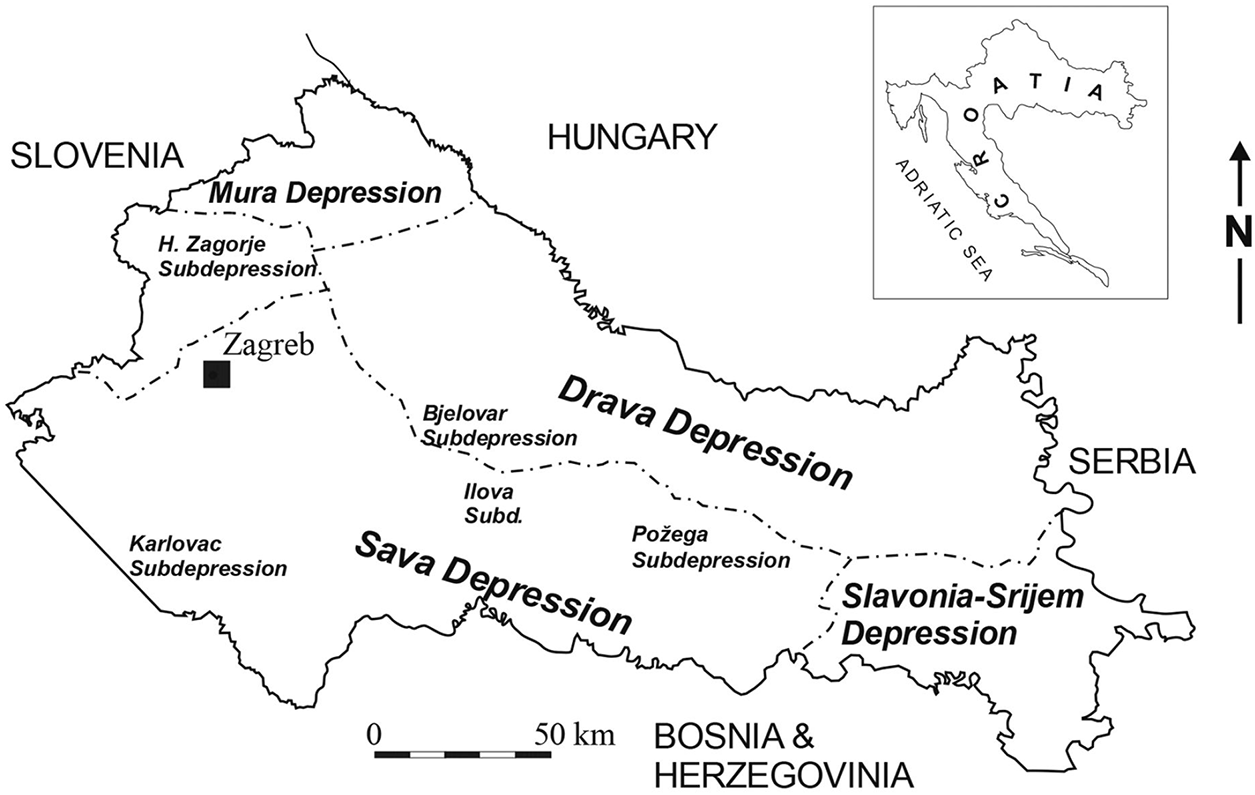
Figure 2: Schematics of Croatian part of the Pannonian Basin and its four main depressions [46]

Figure 3: General geological column of the Mura, Drava and Sava depressions [45]
Thermogeological parameters were calculated at each depth using Jelić’s correlations for rock density, thermal conductivity, and specific heat for the CPBS area [41]. The geothermal gradient in the CPBS is in the range of 0.030°C/m as the minimum and 0.074°C/m as the maximum [42]. The geothermal gradient for this study was set to alternate between 0.034 and 0.050°C/m, with a step of 0.004°C/m. Finally, to determine the available thermal energy, the analysis varied the fluid flow from 10 to 30 l/s in steps of 5 l/s. The parameter changes were applied to model both constant and variable thermal loads.
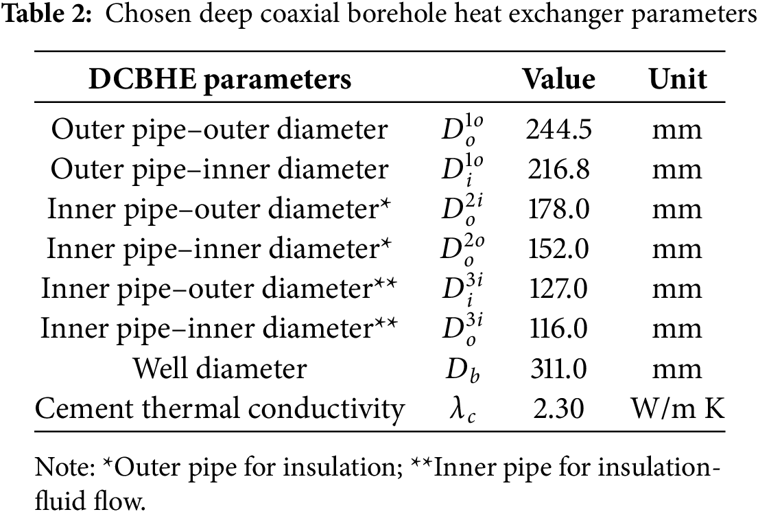
By reviewing the well database drilled in the continental part of Croatia, it was determined that the majority of wells are up to 4000 m in depth, with only a few exploratory wells being deeper. Most of the drilled wells have depths of 1000 to 4000 m. Also, it was determined that the typical diameter of the second casing string (D1) is 244.5 mm (9 5/8″), with a typical well drilling diameter of 311 mm. The diameters of the inner pipe(s) were set to achieve a lower pressure drop in the tubing, while also assuming the installation of an inner pipe for insulation with a vacuum pump. The chosen DCBHE parameters are shown in Table 2. To determine the available thermal energy, different depths were chosen spanning 1000–4000 m with a step of 500 m.
For fluid flow in the DCBHE, the operation of the circulation pump is required. Its operation and energy consumption depend on the pressure drop in the well, i.e., the flow resistance the fluid must overcome. For the fluid flow conditions in the DCBHE (i.e., at different depths and flow rates), the pressure drop in the inner and outer pipes was calculated, accounting for diameter variations. The usual Darcy-Weisbach relation was used for the calculation, under conditions of a pipe surface roughness typical for treated steel pipes (0.035 mm). Density and viscosity were determined for water under standard conditions, so these values were treated as constants. In real conditions, the properties of water change with increasing temperature, i.e., with flow through the borehole heat exchanger. Chen et al. [47] conducted an analysis of the influence of the change in water properties with temperature at the wellhead and at the bottom of a 2600 m deep well and found that the change in thermal properties of water contributes to a difference of 0.9% in the resistance coefficient for the injected and produced fluid. The mentioned difference results in a 1.8% change in the borehole resistance; for the purposes of the calculation, the fixed values can be used.
The available thermal energy from the deep coaxial heat exchanger for various thermogeological and technical settings was determined using the GHX Toolbox, which is based on the FLS heat transfer model [35]. The results for the constant and variable models are presented for two typical thermo-technical systems—direct heating and heat pump use. In a direct heating system, the heat is transferred to the user through plate heat exchangers. In this case, for example, operating leaving source temperature/entering load temperature (LST/ELT) 45°C/40°C was assumed for fan coils or low-temperature radiators. Therefore, thermal loads were set so that the temperature of the borehole exchanger fluid at the outlet of the plate exchanger (i.e., the subcooled inlet fluid to the exchanger) is not less than 45°C for direct heat transfer. In the case of using a heat pump, a lower temperature regime is used, and the assumed LST value is set at 10°C (lower temperature regime), so that the temperature is always above the freezing point.
To determine the available heating loads of deep-borehole heat exchangers for constant operation, the heat load (kW) is set equal for each month over 20 years of DCBHE operation. The results for higher and lower temperature regimes at constant heat loads are seen in Figs. 4 and 5, respectively. The analysis was done by changing the fluid flow rate by 5 l/s (starting at 10 up to 30 l/s), depth of the DCBHE with a step of 500 m of depth (starting at 1500 up to 4000 m), and geothermal gradient with a step of 0.004°C/m (starting at 0.034 up to 0.050°C/m).

Figure 4: Available heating loads for different settings of geothermal gradient (0.034–0.50°C/m), fluid flow (10–30 l/s) and depth (1500–4000 m) of DCBHE for constant load at a higher temperature regime, with ELT set at 40°C

Figure 5: Available heating loads for different settings of geothermal gradient (0.034–0.50°C/m), fluid flow (10–30 l/s) and depth (1500–4000 m) of DCBHE for constant load at a lower temperature regime, with LST set at 10°C (using heat pump)
In contrast, variable heating loads are more common and can be used as a thermo-technical system due to climate- and seasonally driven changes in heating demand. The usual full load hours (FLH) equivalent for heating in continental Croatia is, on average, 1500 h. The analysis was done for the same temperature regimes as for the constant heating loads. The same is true for changes in fluid flow rate, DCBHE depth, and geothermal gradient. Fig. 6 shows the available thermal energy for DCBHE at the higher temperature regime, while Fig. 7 shows the available thermal energy at the lower temperature regime by utilizing heat pumps.
Figure 6: Available thermal energy for different settings of geothermal gradient (0.034–0.50°C/m), fluid flow (10–30 l/s) and depth (1500–4000 m) of DCBHE for variable load at a higher temperature regime, with ELT set at 40°C

Figure 7: Available thermal energy for different settings of geothermal gradient (0.034–0.50°C/m), fluid flow (10–30 l/s) and depth (1500–4000 m) of DCBHE for variable load at a lower temperature regime, with LST set at 10°C (using heat pumps)
Compared with the findings on thermal power/energy discussed in the literature review and shown in Table 1, the thermal power obtained in this research falls within the ranges reported in those studies. Furthermore, the majority of the shown cases are in locations where the geothermal gradient is around the European average of 0.03°C/m. Extensive research of the Croatian part of the Pannonian Basin (CPB) showed that the average gradient is 0.049°C/m, resulting in somewhat higher thermal output due to favorable bottomhole temperatures. Currently, Croatia is developing its geothermal resources by developing classic geothermal projects with brine production wherever possible. Furthermore, initial estimates are also prepared for numerous oil and gas fields with bottom-type aquifers, where geothermal brine production can continue after hydrocarbon depletion [48]. However, numerous wells will remain, mainly exploration wells or those where reservoir permeability will not allow for feasible brine production, which can be reused as geothermal via a DBHE system. Revitalizing such wells and exploiting geothermal energy in smaller district heating systems or in agriculture would lead to much-needed reductions in fossil fuel use in the building sector, which is also a priority at the European level. It would also ensure a local, sustainable, and independent source of heating.
Since the system is not used during the summer months with variable loads, thermal recovery occurs then. Modelling of the DCBHE showed that during those periods, the rock mass temperature around the DCBHE approaches static values. Therefore, at the beginning of each heating season, the system will have more thermal energy available than in the case of continuous load. In the case of an available well at a depth of 1500 m and with lower geothermal gradients of 0.034 and 0.038°C/m, the temperatures achieved are not suitable for direct use of thermal energy, so these values are shown as 0, as well as in the case of choosing a higher temperature class and continuous load. The smallest amount of available thermal energy is at that depth, with a slightly higher geothermal gradient of 0.042°C/m and a flow rate of 10 l/s, yielding 68 MWht. In a lower-temperature regime, where the fluid in the heat exchanger reaches 10°C at peak power and using heat pumps, the available heat energy will be higher than in the direct system and the higher-temperature regime. The available thermal energy is highest at lower temperatures in the system, i.e., when using heat pumps. The temperatures achieved at a depth of 1500 m and the two lower gradients previously mentioned are sufficient to utilize the available thermal energy in this case. With the selected lowest gradient and the smallest flow rate, it is possible to obtain 360 MWht. At a flow of 30 l/s, this amount increases to 373 MWht. Available thermal energy at the highest selected gradient of 0.050°C/m, depth 1500 m, and flow of 10 l/s is 518 MWht, while this amount increases to 539 MWht for an increased flow of 30 l/s. Increasing the depth to 4000 m yields 2475 MWht at the lowest selected gradient and a flow of 10 l/s, rising to 2805 MWh at 30 l/s. The highest available heat energy is achieved with the selected gradient of 0.050°C/m and 30 l/s, at 4095 MWht, and drops to 3615 MWht when the flow drops to 10 l/s. In areas where the geothermal gradient exceeds the selected maximum, higher available thermal energy can be expected.
Determining the power of the circulation pump needed to circulate the working fluid, that is, the consumption of electricity, is related to the fluid flow and pressure drop (Fig. 8a). Typical consumption values for the circulation pump were determined using the Grundfos pump sizing application (available at www.grundfos.com) for flow and pressure drop. According to the selected manufacturer’s offer, there are currently no circulation pumps on the market capable of overcoming pressure drops greater than 30 bar (special orders are not considered). Therefore, based on the available circulating pump consumption from the pump manufacturer, a correlation for pump consumption was determined for each depth (Fig. 8b). Based on the data for real pump power and corresponding pressure drop and fluid flow, a diagram was constructed showing installed pump power and pressure drop for values higher than 30 bar (Fig. 8b). It can be concluded that increasing the pressure drop increases the required installed pump power for water circulation in the DCBHE. From the selected manufacturer of circulation pumps, it is evident that, for DCBHE use, it is necessary to consider that commercially available pumps do not operate with a pressure drop greater than 30 bar. The use of pumps with a pressure drop of over 30 bars is technically possible, however, an inquiry to the factory for the pump design is required. For such a pump, profitability is in question due to high energy consumption and pump pricing. The mentioned limitation has been considered, and the area of application, as shown in Fig. 8a,b, is divided by a black line. The maximum possible consumption of the pump under the specified condition of 30 bar is about 100 kWe, at a depth of 1500 m. Applying the same criterion for the relationship between pressure drop and flow, it is visible at which depths, and for which flows, there are limitations to the use of commercially available circulation pumps. This is considered one of the criteria for evaluating the profitability of deep well revitalization during the design phase.
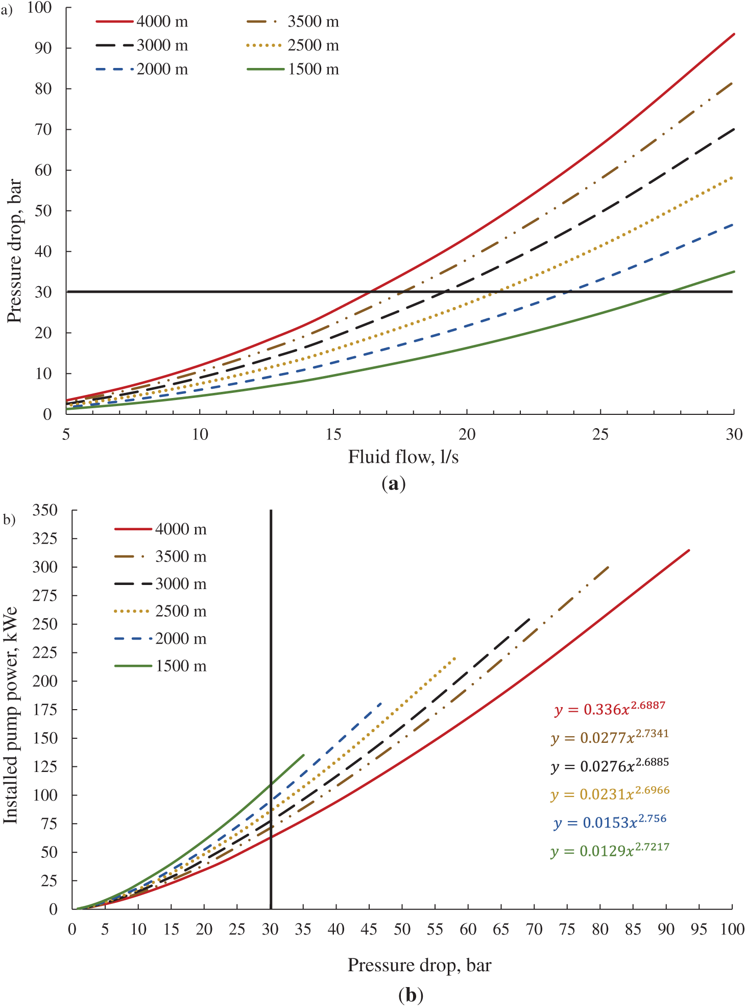
Figure 8: (a) Pressure drop related to fluid flow rate (b) Criteria for selecting wells suitable for revitalization according to the condition of a pressure drop of less than 30 bar, for selected depths
Given that variable thermal energy use is more common in practice, the results of determining the available thermal energy for variable loads in two temperature regimes were used to determine the utilization factor on the DCBHE side. The utilization factor is defined as the ratio of available heat energy to the electrical energy consumed by the circulation pump during operation, also known as the seasonal performance factor (SPF). Given that when determining the available thermal energy at variable load, the system operating time of FLH = 1500 h was assumed, the same was considered when calculating the electricity consumption for the circulation pump. With increased depth and decreased pressure, the electricity required for fluid circulation through the DBHE increases. The value of the SPF factor also increases because, with increasing depth, the available heat energy increases. Although at greater depths it is necessary to invest more energy in fluid circulation, the available thermal energy is sufficiently high to achieve a higher utilization factor for the well heat exchanger. As was previously determined in real systems, from a hydraulic point of view, the pressure drop should not exceed 30 bar, considering commercially available circulation pump models. Due to the mentioned limitation, which satisfies such a condition, even though the SPF factors are of positive value, only a few cases are singled out and shown, for simplicity, for geothermal gradients of 0.034, 0.042 and 0.05°C/m, for both higher and lower temperature regimes (Figs. 9 and 10).

Figure 9: Relationship between the SPF factor and the available thermal energy from a DCBHE, for a higher temperature regime (ELT = 40°C) with variable load (criteria of optimal pressure drop)
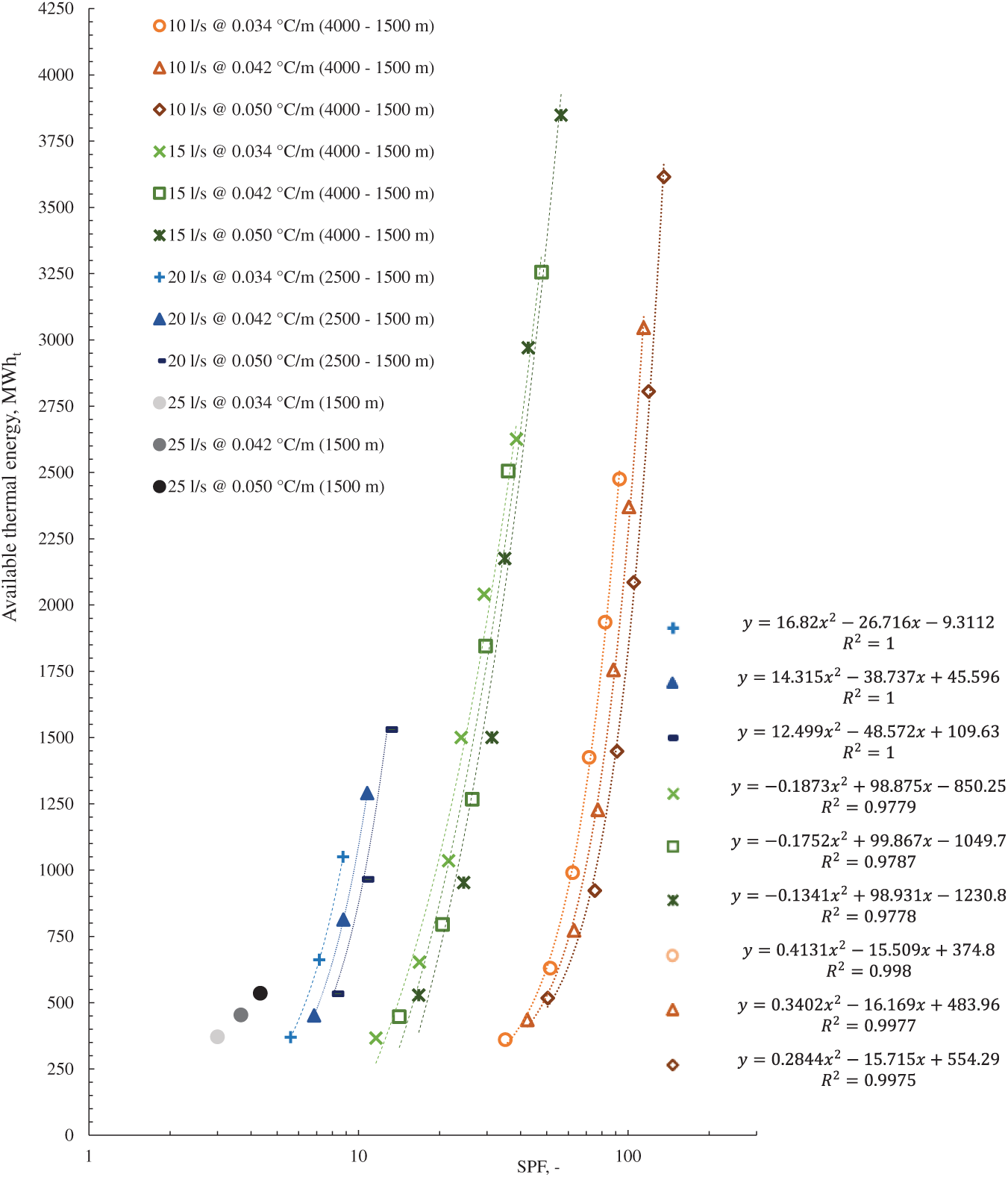
Figure 10: Relationship between the SPF factor and the available thermal energy from a DCBHE, for the lower temperature regime (LST = 10°C) with variable load (criteria of optimal pressure drop)
For a particular condition of geothermal gradient and flow, the relationship between the available thermal energy and the SPF factor can be described by the corresponding second-order polynomial curves. Although in all cases the SPF factor had positive values, except for those in which the temperature at depth was lower than the designed temperature, cases with a pressure drop greater than 30 bar were discarded. It is also evident that, for higher thermal energy values, the expected SPF factor is higher. Namely, for the circulation pump, the same amount of electricity is required as for a higher-temperature class. However, more thermal energy is available at lower temperatures. Thus, for example, at a higher temperature regime, a flow rate of 10 l/s, a DCBHE depth of 4000 m, and a geothermal gradient of 0.050°C/m, the SPF factor will be 41, while at a lower temperature class, under the same conditions, it will be 136, i.e., about three times more.
According to the presented diagrams, it is evident that the levels of thermal energy available from abandoned wells, if retrofitted with DCBHE, are more than sufficient for use in real heating systems. By reviewing the locations of wells in Croatia, it can be concluded that fewer are in urban areas, where they could be used in central heating systems. The majority of them are located in or near agricultural areas and the peripheral parts of smaller or larger settlements. From this perspective, revitalized oil and gas abandoned wells are suitable for exploitation in the agricultural sector for greenhouse heating, in industrial zones for heating workspaces (e.g., halls), and in general for heating business and residential buildings. In most cases, thermal energy is used seasonally/variably. The techno-economic analysis is therefore based on a variable thermal load example, for both higher and lower thermal regimes, in accordance with the results of the available thermal energy calculation. The results are presented for three chosen geothermal gradients and for two thermal regimes at the thermo-technical system (user side) at 35°C/30°C (underfloor heating) and 45°C/40°C (fan coils or low-temperature radiators), for higher (Fig. 10) and lower (Fig. 11) temperature regimes. Based on two different temperature regimes, the basis for setting up the techno-economic model is provided, focusing on the annual costs of energy sources and their comparison. For the model, some simplifications were introduced. Facilities that use revitalized DCBHE as a primary energy resource should be located relatively close to the borehole, in order to limit the heat loss on the external infrastructure as much as possible (flow and return pipes from the DCBHE to the plate heat exchanger, and flow and return pipes from the heat exchanger to the user). The loss of thermal energy can be limited by installing insulated pipelines, since the design of each system is individualized, that is, the required length of pipes for the external system is not fixed. The techno-economic analysis of operating cost was therefore made under the assumption that there are no thermal energy losses in the thermo-technical surface system.
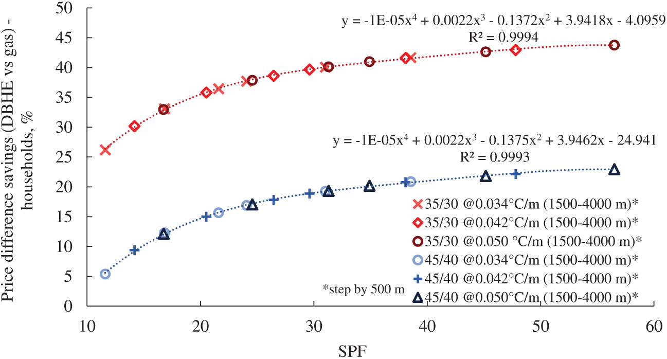
Figure 11: Percentage of operational cost savings by using the DCBHE for households with the fluid flow of 15 l/s
The gas prices used for the analysis are the average household gas price for 2022 and the average gas price, excluding VAT, for businesses (non-households) from Eurostat data for 2022 [Eurostat]. Electricity consumption for households is determined based on the system operating time (FLH), required for the operation of the circulation pump at a lower temperature regime, in a two-tariff system (2/3 of the total amount belongs to the high-tariff class, VT, while 1/3 refers to the low-tariff class, NT). The HEP calculator (https://hepi.hep.hr) was used to determine the electricity price for the white tariff system. For the non-household, the average price of electricity, excluding VAT, for entrepreneurs according to Eurostat statistics for 2022 [Eurostat] was taken. In order for the gas system to deliver the amount of thermal energy available from the DCBHE, it is necessary to take into account the utilization of the gas boiler (85%) and based on the calculated required energy of the gas system, gas prices for households and non-households were calculated according to the average gas prices for 2022. The results are shown in Fig. 11 for the lower-temperature regime, expressed as the % savings achieved if the DCBHE were used for seasonal heating instead of the more popular natural gas for households, and in Fig. 12 for non-household users.
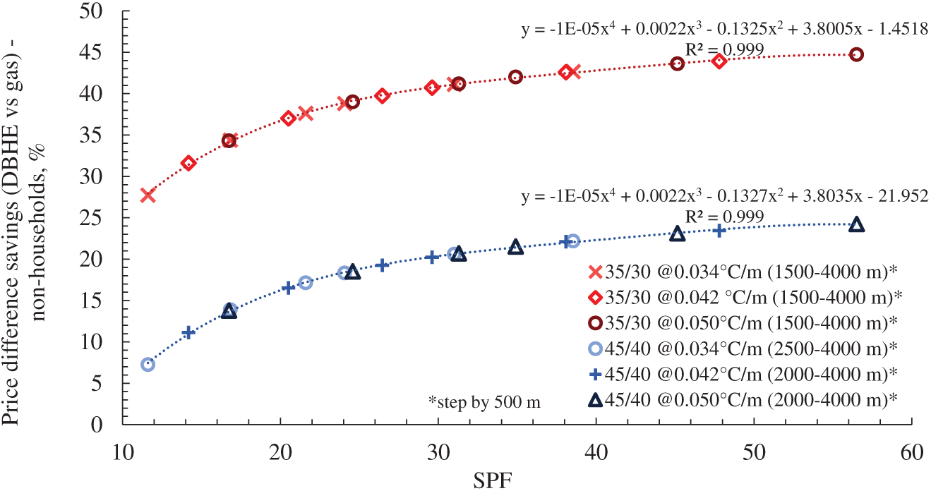
Figure 12: Percentage of operational cost savings by using the DCBHE for non-households with the fluid flow of 15 l/s
The average cost of creating and equipping a new geothermal well was around 1800 EUR/m in 2021 [personal communication]. Given that revitalizing abandoned oil and gas wells represents an investment that is almost seven times smaller than the construction and equipment of a new geothermal well, it is necessary to determine the depths at which the revitalization process is cost-effective, given the available thermal energy. As for the capital costs of the revitalization of temporarily abandoned oil and gas wells, it is necessary to take into account the cost of renting and operating a workover rig, the cost of testing the quality of cement stone bonding, and the hydraulic and mechanical integrity of the well channel, the cost of possible remedial cementing (squeezing), the cost of procurement and installation of tubing, the cost of purchasing, installing and activating the isolation tool (packer), the cost of purchasing a pump to maintain the circulation of the working fluid. The costs of renting a workover rig are always determined on the basis of market mechanisms at a certain moment, that is, on the principle of supply and demand, and ultimately on the basis of the movement of oil prices and the purpose and type of the workover rig itself. The average daily cost of renting a workover rig was usually between €4100 and €8300 in 2021, with rental prices varying by region and the type of workover rig. In addition to the daily rental price of the workover rig, it is necessary to consider the costs of mobilizing and demobilizing the rig, as well as the personnel performing the workover.
The capital costs of revitalizing abandoned oil and gas wells increase with the depth of the well. Well depths ranging from 1500 to 4000 m, with a step of 500 m, were considered. Here, typical geothermal gradients were considered, ranging from 0.034 to 0.05°C/m, with a step of 0.004°C/m. Well revitalization costs are an exclusive function of well depth and were estimated at around 250 EUR/m [personal communication].
For variable thermal loads, two cases of inlet temperature for the working fluid were considered, i.e., higher and lower temperature regimes. In comparing the two versions of the geothermal heat system, the lower-temperature version is much better because it uses a much larger amount of thermal energy and returns the subcooled working fluid to the borehole heat exchanger at 10°C. As stated earlier, the capital cost of revitalization is an exclusive function of the depth of the well, and the costs of revitalizing wells for the exploitation of geothermal heat energy range from 372,000 EUR for well depths of 1500 m, and up to around 1 million EUR for depths of 4000 m deep well (Fig. 13). The return on investment for deep-borehole heat exchangers depends on the amount of available thermal energy per heating season. At the same time, the capital cost of the produced thermal energy varies from 13 EUR/MWh to over 55 EUR/MWh. The cost, the amount of geothermal heat energy produced from revitalized abandoned oil and gas wells, and the well’s depth depend on the specific geothermal gradient of the area where the well is located. Therefore, the highest available thermal energy and the most favourable cost of thermal energy production from deep-borehole coaxial heat exchangers will be achieved at greater borehole depths and higher geothermal gradients. Fig. 13 shows a graph of capital investment costs as a function of specific geothermal gradients across the CPBS. The graph clearly shows that the investment value decreases with higher geothermal gradients and greater well depths.
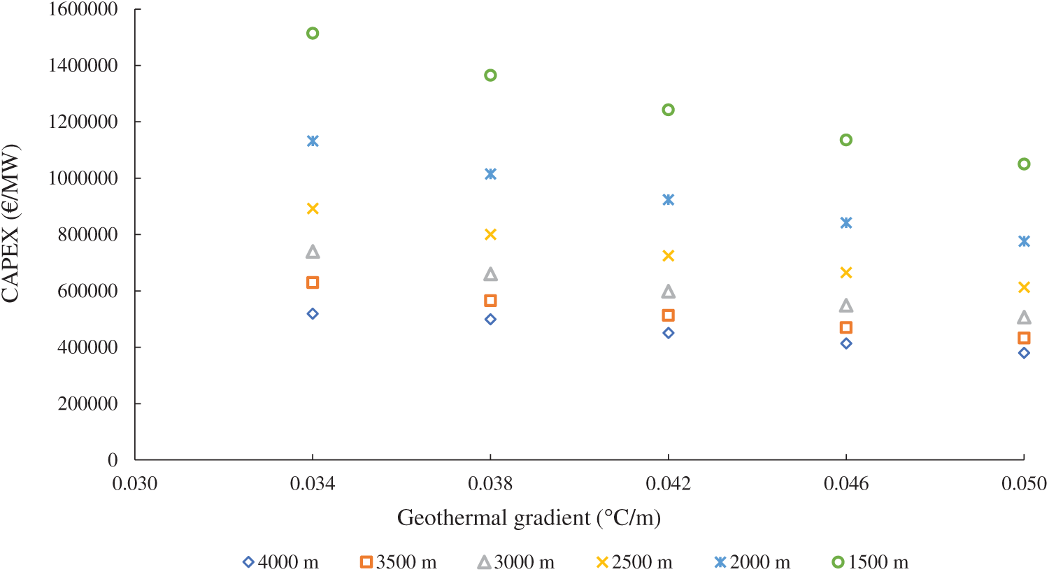
Figure 13: Capital cost of well revitalization with variable heat load for a lower temperature regime depending on the amount of available heat energy
In the next few years, there will be a transition period towards the production and use of electricity and thermal energy from renewable energy sources. It is evident from the EU energy and climate strategies and new energy analyses for the Republic of Croatia that, to a certain extent, geothermal energy is also being counted on. In the forecasts, the exploitation of these sources is reduced to the greatest extent possible, with the use of classic power production systems or thermal energy. Most projections do not account for the possibility of producing heat and electricity from geothermal resources by revitalizing abandoned oil, gas and exploration wells. Systematic research into the potential of available geothermal energy from revitalized abandoned wells has not yet been conducted in the Republic of Croatia. Therefore, the goals of this research are defined by the quantification of the geothermal energy potential of the continental part of the Republic of Croatia using revitalized boreholes with deep borehole heat exchangers and the creation of a conceptual model by linking the thermogeological characteristics of the rock mass, the technical parameters of the borehole, and the generated thermal power.
The process of revitalizing abandoned deep wells into deep coaxial borehole heat exchangers is acceptable to implement, as it yields almost climate-neutral geothermal heat energy with almost no net greenhouse gas emissions, especially since it relies on closed-loop circulation of the working fluid. At the same time, the maximum energy potential of an oil, gas, or exploration well is used even after abandonment. The results show that it is economically justified to revitalize abandoned wells if certain conditions are met, including well depth, geothermal gradient, and other parameters. It can be concluded that the revitalization project would be more profitable with a deeper and more pronounced geothermal gradient. The biggest obstacle to well revitalization is the well’s age and whether it is active or completely abandoned. Deep wells that are inactive, fully abandoned over 30 or 40 years ago, are not good candidates due to cement bond degradation over time and questions about casing condition. The best candidates would be wells that were active at least up to 10 years ago and for which the well history is well-known. Furthermore, the location of the well is also important. If the well is not in the vicinity of potential consumers, the feasibility of revitalizing a single well is questionable. In the Croatian part of the Pannonian Basin, most of the wells, as well as active hydrocarbon fields, are in rural areas, where agricultural production is active. The use of geothermal energy in communities where smaller district heating systems or greenhouses in agriculture is feasible would certainly benefit from lower capital investment in a secure, reliable heating resource. Even though the benefits are clear, the obstacles are seen in the underdeveloped DH system surface equipment. Other than a few larger cities, most of the heating in Croatia is individual gas boilers or biomass systems. Therefore, to prepare for such investments, it would be prudent to plan and develop surface infrastructure in areas where wells for revitalization are identified. Future energy policy should address the continued use of hydrocarbon infrastructure to expedite the development of projects that fully utilize available geothermal resources. Such policies should support the development of currently underdeveloped district heating systems and increase the area under greenhouses. Additionally, the DBHE technology, along with other revitalization technologies, should be addressed in future policy, along with concrete steps, which are currently lacking (i.e., currently there is no standard procedure in legislation and policy on how to revitalize a well via DBHE, the concession fee is not defined for the case of DBHE or BTES, only for brine production, etc.). Such policy changes will incentivize investors to consider well revitalization as a feasible option for developing a geothermal project with lower capital investment and to increase geothermal energy utilization in the Croatian energy mix. This research shows strong potential for obtaining thermal energy through well revitalization and the use of DBHE, and it should have a place in future policy and legislative development.
A model of utilizing geothermal energy through well revitalization aligns with the circular economy, one of the key economic policies of the European Union, which aims to use resources multiple times before they are discarded or disposed of appropriately. Therefore, obtaining thermal energy from abandoned oil, gas, and exploration wells, whose potential as a valuable energy resource is still not sufficiently recognized, can play an important role in the process of decarbonization of the industrial and heating sectors. Finally, based on the example of revitalization and calculation of available heat energy for different parameters of depth, flow, and geothermal gradient, a process model was created as a basis for future estimates of available heat energy using deep well heat exchangers and techno-economic analysis in order to help with the process of deciding which well can be considered for revitalization (Fig. 14).
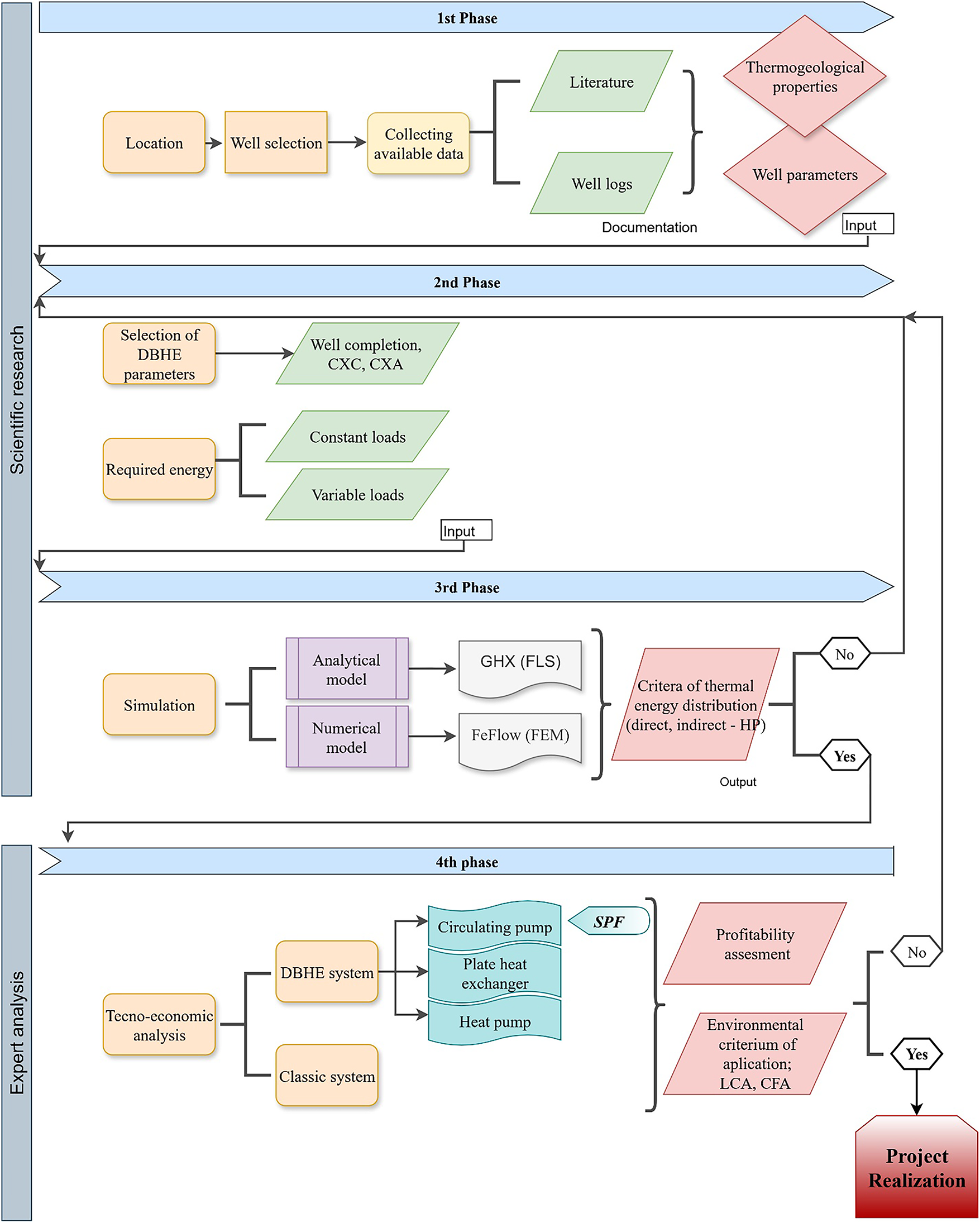
Figure 14: A complete workflow for evaluating the profitability of the revitalization of abandoned wells
Acknowledgement: This research was carried out under Interreg CE TRANSGEO project activities.
Funding Statement: The authors received no specific funding for this study.
Author Contributions: The authors confirm contribution to the paper as follows: study conception and design: Marija Macenić, Tomislav Kurevija; data collection: Marija Macenić, Tomislav Kurevija; analysis and interpretation of results: Marija Macenić, Tomislav Kurevija, Tin Herbst; draft manuscript preparation: Marija Macenić, Tomislav Kurevija, Tin Herbst. All authors reviewed the results and approved the final version of the manuscript.
Availability of Data and Materials: Data available on request from the authors. The data that support the findings of this study are available from the corresponding author, [Tomislav Kurevija], upon reasonable request.
Ethics Approval: Not applicable.
Conflicts of Interest: The authors declare no conflicts of interest to report regarding the present study.
Glossary
| Pipe diameter, (mm) | |
| Euler number (2.7183) | |
| ELT | Entering load temperature, (°C) |
| g | Eskilson’s g-function |
| Borehole depth, (m) | |
| LST | Leaving source temperature, (°C) |
| Heat power per meter of a borehole, (W/m) | |
| Radius, (m) | |
| Wellbore radius, (m) | |
| Equivalent borehole thermal resistance, (m K/W) | |
| Skin factor, - | |
| Time, (s) | |
| Time at which steady-state heat transfer is achieved | |
| Temperature, (°C) | |
| Initial borehole temperature, (°C) | |
| Temperature in function of radius and time, (°C) | |
| Greek Symbols | |
| Thermal diffusivity, (m2/s) | |
| Temperature drop/rise due to skin effect, (°C) | |
| Euler’s constant ( | |
| Thermal conductivity, (W/m K) | |
| Abbreviations | |
| BHE | Borehole heat exchanger |
| CAPEX | Capital cost |
| CPBS | The croatian part of the pannonian basin |
| DBHE | Deep borehole heat exchanger |
| DCBHE | Deep coaxial borehole heat exchanger |
| FLH | Full load hours |
| FLS | Finite line source model |
| ILS | Infinite line source model |
| SPF | Seasonal performance factor |
| VIT | Vacuum insulated tubing |
References
1. Morita K, Matsubayashi O, Kusunoki K. Down-hole coaxial heat exchanger using insulated inner pipe for maximum heat extraction. Geotherm Resour Counc Trans. 1985;9(1):45–50. [Google Scholar]
2. Bu X, Ma W, Li H. Geothermal energy production utilizing abandoned oil and gas wells. Renew Energy. 2012;41:80–5. doi:10.1016/j.renene.2011.10.009. [Google Scholar] [CrossRef]
3. Campbell K, Smith R. Permanent well abandonment. Way Ahead. 2013;9(3):25–7. doi:10.2118/0313-025-twa. [Google Scholar] [CrossRef]
4. Fanailoo P, Buchmiller D, Ouyang S, Allen E, Buchmiller D. Risk based approach to well plugging & abandoning-reducing costs while verifying risk. In: Proceedings of the Offshore Technology Conference; 2017 May 1–4; Houston, TX, USA. doi:10.4043/27921-ms. [Google Scholar] [CrossRef]
5. Kang M, Christian S, Celia MA, Mauzerall DL, Bill M, Miller AR, et al. Identification and characterization of high methane-emitting abandoned oil and gas wells. Proc Natl Acad Sci U S A. 2016;113(48):13636–41. doi:10.1073/pnas.1605913113. [Google Scholar] [PubMed] [CrossRef]
6. Kohl T, Brenni R, Eugster W. System performance of a deep borehole heat exchanger. Geothermics. 2002;31(6):687–708. doi:10.1016/S0375-6505(02)00031-7. [Google Scholar] [CrossRef]
7. Kohl T, Salton M, Rybach L. Data analysis of the deep borehole heat exchanger plant Weissbad (Switzerland). In: Proceedings of the World Geothermal Congress; 2000 May 28–Jun 10; Kyushu-Tohoku, Japan. p. 3459–64. [Google Scholar]
8. Link K, Rybach L, Imhasly S, Wyss R. Geothermal energy in Switzerland-country update. In: Proceedings of the World Geothermal Congress 2015; 2015 Apr 19–25; Melbourne, Australia. [Google Scholar]
9. Dijkshoorn L, Speer S, Pechnig R. Measurements and design calculations for a deep coaxial borehole heat exchanger in Aachen. Germany Int J Geophys. 2013;2013(1):916541. doi:10.1155/2013/916541. [Google Scholar] [CrossRef]
10. Wang Z, Wang F, Liu J, Ma Z, Han E, Song M. Field test and numerical investigation on the heat transfer characteristics and optimal design of the heat exchangers of a deep borehole ground source heat pump system. Energy Convers Manag. 2017;153:603–15. doi:10.1016/j.enconman.2017.10.038. [Google Scholar] [CrossRef]
11. Chen H, Tomac I. Feasibility of coaxial deep borehole heat exchangers in southern California. Geotherm Energy. 2024;12(1):41. doi:10.1186/s40517-024-00319-0. [Google Scholar] [CrossRef]
12. Kujawa T, Nowak W, Stachel AA. Utilization of existing deep geological wells for acquisitions of geothermal energy. Energy. 2006;31(5):650–64. doi:10.1016/j.energy.2005.05.002. [Google Scholar] [CrossRef]
13. Alimonti C, Soldo E. Study of geothermal power generation from a very deep oil well with a wellbore heat exchanger. Renew Energy. 2016;86:292–301. doi:10.1016/j.renene.2015.08.031. [Google Scholar] [CrossRef]
14. Davis AP, Michaelides EE. Geothermal power production from abandoned oil wells. Energy. 2009;34(7):866–72. doi:10.1016/j.energy.2009.03.017. [Google Scholar] [CrossRef]
15. Templeton JD, Ghoreishi-Madiseh SA, Hassani F, Al-Khawaja MJ. Abandoned petroleum wells as sustainable sources of geothermal energy. Energy. 2014;70:366–73. doi:10.1016/j.energy.2014.04.006. [Google Scholar] [CrossRef]
16. Noorollahi Y, Taghipoor S, Sajadi B. Geothermal sea water desalination system (GSWDS) using abandoned oil/gas wells. Geothermics. 2017;67(1):66–75. doi:10.1016/j.geothermics.2017.01.008. [Google Scholar] [CrossRef]
17. Li J, Zhu T, Li F, Wang D, Bu X, Wang L. Performance characteristics of geothermal single well for building heating. Energy Eng. 2021;118(3):517–34. doi:10.32604/ee.2021.014464. [Google Scholar] [CrossRef]
18. Li H, Wang J, Liu S, Tang L, Zhang X, Wang P. Study on heat extraction capacity of deep coaxial borehole heat exchanger equipped with spiral-finned inner tube. Int J Heat Fluid Flow. 2025;116:109946. doi:10.1016/j.ijheatfluidflow.2025.109946. [Google Scholar] [CrossRef]
19. Li J, Xu W, Li J, Huang S, Li Z, Qiao B, et al. Heat extraction model and characteristics of coaxial deep borehole heat exchanger. Renew Energy. 2021;169:738–51. doi:10.1016/j.renene.2021.01.036. [Google Scholar] [CrossRef]
20. Zhang Q, Liu F, Han Y, Gao X, Pang H. Numerical analysis of the heat extraction performance of a U-type medium-deep borehole heat exchanger utilizing supercritical CO2 as a heat-carrying fluid. Appl Therm Eng. 2025;279:127834. doi:10.1016/j.applthermaleng.2025.127834. [Google Scholar] [CrossRef]
21. Chen H, Liu H, Yang F, Tan H, Wang B. Field measurements and numerical investigation on heat transfer characteristics and long-term performance of deep borehole heat exchangers. Renew Energy. 2023;205:1125–36. doi:10.1016/j.renene.2023.02.021. [Google Scholar] [CrossRef]
22. Gola G, Di Sipio E, Facci M, Galgaro A, Manzella A. Geothermal deep closed-loop heat exchangers: a novel technical potential evaluation to answer the power and heat demands. Renew Energy. 2022;198:1193–209. doi:10.1016/j.renene.2022.08.071. [Google Scholar] [CrossRef]
23. Landau M, Seib L, Bossennec C, Handke H, Muhl J, Stumpf J, et al. Drilling engineering experience gained from MD-BTES construction phase of SKEWES demo-site. In: Proceedings of the 25th EGU General Assembly; 2023 Apr 23–28; Vienna, Austria. [Google Scholar]
24. PUSH-IT Project. Pilot Site Darmstadt (Germany). [cited 2025 Jan 1]. Available from: https://www.push-it-thermalstorage.eu/pilots/darmstadt/. [Google Scholar]
25. PUSH-IT Project. Pilot Site Litoměřice (Czechia). [cited 2025 Jan 1]. Available from: https://www.push-it-thermalstorage.eu/pilots/litomerice/. [Google Scholar]
26. Eavor. [cited 2025 Jan 1]. Available from: https://eavor.com/. [Google Scholar]
27. Eavor-Lite. [cited 2025 Jan 1]. Available from: https://eavor.com/eavor-lite/. [Google Scholar]
28. In Geretsried schreibt Eavor das nächste Kapitel der Energiewende. [cited 2025 Jan 1]. Available from: https://eavor.de/projekt-geretsried/. [Google Scholar]
29. Amaya A, Scherer J, Muir J, Patel M, Higgins B. GreenFire energy closed-loop geothermal demonstration using supercritical carbon dioxide as working fluid. In: Proceedings of the 45th Workshop on Geothermal Reservoir Engineering; 2020 Feb 10–12; Stanford, CA, USA. p. 10–2. [Google Scholar]
30. Republic of Slovenia: Ministry of Cohesion and Regional Development MKRR [Internet]. 2022 [cited 2025 Jan 1]. Available from: https://si-geo-electricity.si/en/about-the-project/. [Google Scholar]
31. Zhang Y, Yu C, Li G, Guo X, Wang G, Shi Y, et al. Performance analysis of a downhole coaxial heat exchanger geothermal system with various working fluids. Appl Therm Eng. 2019;163:114317. doi:10.1016/j.applthermaleng.2019.114317. [Google Scholar] [CrossRef]
32. Kolo I, Brown CS, Falcone G, Banks D. Closed-loop deep borehole heat exchanger: newcastle science central deep geothermal borehole. In: Proceedings of the European Geothermal Congress 2022; 2022 Oct 17–21; Berlin/Heidelberg, Germany. [Google Scholar]
33. The Slovenia Times. Pilot geothermal plant generates electricity, but modifications required [Internet]. 2024 [cited 2025 Jan 1]. Available from: https://sloveniatimes.com/40419/pilot-geothermal-plant-generates-electricity-but-modifications-required. [Google Scholar]
34. Fourier J. Theorie analytique de la chaleur. Paris, France: Firmin Didot, père et fils; 1822. [Google Scholar]
35. Chiasson AD. Geothermal heat pump and heat engine systems: theory and practice. Hoboken, NJ, USA: John Wiley & Sons; 2016. doi:10.1002/9781118961957. [Google Scholar] [CrossRef]
36. Claesson J, Eskilson P. Conductive heat extraction to a deep borehole: thermal analyses and dimensioning rules. Energy. 1988;13(6):509–27. doi:10.1016/0360-5442(88)90005-9. [Google Scholar] [CrossRef]
37. Kurevija T, Strpić K, Koščak-Kolin S. Applying petroleum the pressure buildup well test procedure on thermal response test—a novel method for analyzing temperature recovery period. Energies. 2018;11(2):366. doi:10.3390/en11020366. [Google Scholar] [CrossRef]
38. Hellström GAJ. Ground heat storage: thermal analyses of duct storage systems. I. Theory. Lund, Sweden: Lund University; 1991. [Google Scholar]
39. Al-Khoury R, Bonnier PG, Brinkgreve RBJ. Efficient finite element formulation for geothermal heating systems. Part I: steady state. Numer Meth Eng. 2005;63(7):988–1013. doi:10.1002/nme.1313. [Google Scholar] [CrossRef]
40. Śliwa T, Kruszewski M, Sapińska-Śliwa A, Assadi M. The application of vacuum insulated tubing in deep borehole heat exchangers. Drill. 2017;34(2):597. doi:10.7494/drill.2017.34.2.597. [Google Scholar] [CrossRef]
41. Jelić K. Thermic properties of sedimentation complex of southwest region of Pannonian Basin (Original: Termičke osobine sedimentacionog kompleksa jugozapadnog dijela Panonskog bazena) [dissertation]. Zagreb, Croatia: University of Zagreb; 1979. [Google Scholar]
42. Macenić M, Kurevija T, Medved I. Novel geothermal gradient map of the Croatian part of the Pannonian Basin system based on data interpretation from 154 deep exploration wells. Renew Sustain Energy Rev. 2020;132:110069. doi:10.1016/j.rser.2020.110069. [Google Scholar] [CrossRef]
43. Velić J, Malvić T, Cvetković M, Vrbanac B. Reservoir geology, hydrocarbon reserves and production in the Croatian part of the Pannonian Basin. Geol Croat. 2012;65(1):91–101. doi:10.4154/gc.2012.07. [Google Scholar] [CrossRef]
44. Saftić B, Velić J, Sztano O, Juhasz G, Ivković Ž., Zagreb INDD. Tertiary subsurface facies, source rocks and hydrocarbon reservoirs in the SW part of the pannonian basin (northern Croatia and south-western Hungary). Geol Croat. 2003;56(1):101–22. doi:10.4154/232. [Google Scholar] [CrossRef]
45. Durn T, Krpan M. Onshore Croatia: hydrocarbon opportunities at the crossroads of Europe. London, UK: GeoExPro-Petroleum Geoscience Magazine; 2016. [Google Scholar]
46. Malvić T. Regional turbidites and turbiditic environments developed during Neogene and Quaternary in Croatia. Mater Geoenviron. 2016;63(1):39–54. doi:10.1515/rmzmag-2016-0004. [Google Scholar] [CrossRef]
47. Chen C, Shao H, Naumov D, Kong Y, Tu K, Kolditz O. Numerical investigation on the performance, sustainability, and efficiency of the deep borehole heat exchanger system for building heating. Geotherm Energy. 2019;7(1):18. doi:10.1186/s40517-019-0133-8. [Google Scholar] [CrossRef]
48. Tuschl M, Kurevija T. Revitalization modelling of a mature oil field with bottom-type aquifer into geothermal resource—reservoir engineering and techno-economic challenges. Energies. 2023;16(18):6599. doi:10.3390/en16186599. [Google Scholar] [CrossRef]
Cite This Article
 Copyright © 2026 The Author(s). Published by Tech Science Press.
This work is licensed under a Creative Commons Attribution 4.0 International License , which permits unrestricted use, distribution, and reproduction in any medium, provided the original work is properly cited.
 Downloads
 Citation Tools