
 Submit a Paper
 Propose a Special lssue
 Open Access
ARTICLE

Low-Carbon Economic Dispatch of an Integrated Energy System with Multi-Device Coupling under Ladder-Type Carbon Trading
School of Electrical Engineering, Shanghai Dianji University, Shanghai, 201306, China
* Corresponding Author: Yongqing Qi. Email:
Energy Engineering 2026, 123(2), 12 https://doi.org/10.32604/ee.2025.069878
Received 02 July 2025; Accepted 13 August 2025; Issue published 27 January 2026
 View Full Text
 Download PDF
Abstract
To enhance the low-carbon economic efficiency and increase the utilization of renewable energy within integrated energy systems (IES), this paper proposes a low-carbon dispatch model integrating power-to-gas (P2G), carbon capture and storage (CCS), hydrogen fuel cell (HFC), and combined heat and power (CHP). The P2G process is refined into a two-stage structure, and HFC is introduced to enhance hydrogen utilization. Together with CCS and CHP, these devices form a multi-energy conversion system coupling electricity, heat, cooling, and gas. A ladder-type carbon trading approach is adopted to flexibly manage carbon output by leveraging marginal cost adjustments. To evaluate the resilience of the proposed low-carbon scheduling strategy involving multiple energy units under the variability of renewable energy, a two-level robust optimization framework is developed. This model captures the most adverse scenarios of wind and solar generation. The dispatch strategy is validated against these extreme conditions to demonstrate its flexibility and effectiveness. The problem is solved using the GUROBI optimization tool. Results from simulations indicate that the model increases renewable energy integration by 39.1%, and achieves reductions of 15.96% in carbon emissions and 16.29% in operational expenditures. The results demonstrate that the strategy ensures both economic efficiency and environmental performance under uncertain conditions. Compared with existing studies that separately model two-stage P2G or CCS devices, this paper integrates HFC, CHP, and CCS into a unified dispatchable system, enabling refined hydrogen utilization and flexible carbon circulation. Furthermore, the introduction of a ladder-type carbon pricing mechanism, combined with multi-energy storage participation in implicit demand response, creates a dynamic and cost-sensitive dispatch framework. These modeling strategies go beyond conventional linear IES formulations and provide more realistic system representations. The proposed approach not only deepens the coupling among electric, thermal, and gas systems, but also offers a feasible pathway for high-penetration renewable integration in low-carbon energy systems.Keywords
As global energy consumption surges, exacerbating environmental degradation and climate concerns, the acceleration of energy system reform has become critical for achieving carbon emission reductions [1]. IES address this challenge by mitigating the limitations of conventional siloed planning and operation across multiple energy domains—including electricity, heating, cooling, gas, and hydrogen. Through coordinated optimization and cross-energy integration, IES enable more sustainable, secure, and cost-effective energy usage. Their growth significantly contributes to enhancing the uptake of RES, which in turn helps curtail overall fossil fuel dependence and carbon emission [2]. Currently, extensive research worldwide focuses on key aspects of IES, such as the collaborative scheduling of multiple energy units, environmentally friendly economic dispatch strategies, demand-side flexibility assessment, and strategies for mitigating uncertainties in RES output and load prediction [3].
Carbon trading has gained widespread recognition as a highly effective policy tool for curbing greenhouse gas emissions [4]. Prior research, such as that in [5,6], explores the cost-efficient and low-emission operation of IES under carbon trading frameworks, indicating that such approaches contribute both to emission mitigation and operational savings. In [7], a wind power-integrated system is examined with an embedded carbon market, where its influence on conventional dispatch strategies is assessed. A comparative study in [8] evaluates the performance differences between flat-rate and ladder-type carbon pricing models, focusing on their respective impacts on system cost-efficiency and emission levels. The study in [9] incorporates a ladder-type carbon pricing strategy into the long-term planning of IES, yielding a significant reduction in total emissions. Likewise, Ref. [10] integrates carbon trading into centralized scheduling of electricity-gas-thermal systems, validating through simulation that applying a ladder-type pricing scheme enhances the effectiveness of low-carbon economic dispatch. These studies confirm that the integration of carbon trading mechanisms into IES is effective for promoting low-carbon and cost-efficient operations, and that ladder-type carbon pricing generally demonstrates superior performance in emission reduction. However, most existing works treat carbon trading as a linear cost term, which fails to capture the progressive nature of marginal carbon pricing under real-world policy frameworks, thereby weakening the emission-reduction incentive. In contrast, the ladder-type carbon trading mechanism introduces ladder-type pricing across predefined emission intervals, aligning more closely with the structural characteristics of actual carbon markets. This not only helps maintain economic efficiency but also enhances the driving force for carbon mitigation. Building upon a multi-device coordinated optimization model for IES, this paper introduces a segmented, ladder-type carbon pricing mechanism. This study allows differentiated constraints on carbon emissions while improving the model’s adaptability to various policy scenarios. As a result, it more accurately reflects how emission reduction targets influence system operation strategies and offers higher practical value and policy relevance.
In recent years, hydrogen energy has gained significant interest and rapid development owing to its high energy conversion efficiency, excellent storage capabilities, and minimal environmental impact. Within IES, P2G serves as the primary approach for hydrogen integration. By transforming excess electrical energy into synthetic methane, P2G strengthens the interconnection between electricity and gas infrastructures while minimizing energy losses associated with multistage conversions [11]. In [12], a collaborative operational strategy combining CHP, P2G, and CCS technologies is proposed, and results indicate that this configuration effectively boosts renewable energy absorption and lowers greenhouse gas emissions. However, most existing studies oversimplify the P2G process as a single-stage gas production mechanism, without explicitly modeling the two key stages—electrolytic hydrogen production (EL) and methanation reaction (MR)—and their respective energy flows. In reality, the P2G process comprises these two distinct stages [13], with the intermediate hydrogen production phase offering higher energy conversion efficiency. Therefore, a refined modeling approach that captures the internal structure of P2G, particularly the energy utilization pathway of intermediate hydrogen, is crucial for enabling efficient and clean use of hydrogen energy. According to Reference [14], the adoption of a two-level P2G system contributes to lowering operational expenditures while enhancing the efficiency of energy utilization. Moreover, Reference [15] integrates two-stage P2G with CCS technology into the IES framework and validates the proposed model in terms of its economic, environmental, and energy-related benefits.
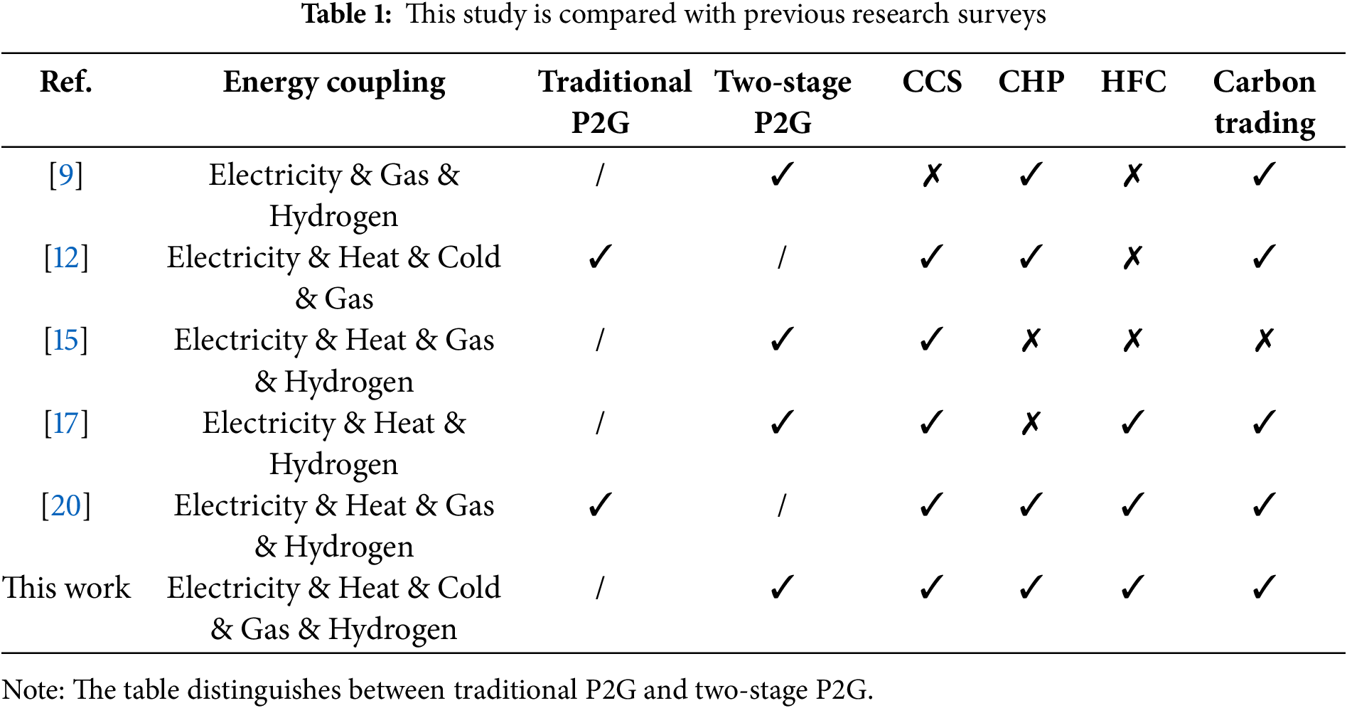
However, merely introducing a two-stage P2G structure still presents limitations, as it routes hydrogen energy exclusively toward methane production. This narrow conversion pathway restricts hydrogen’s flexible use across diverse scenarios and, coupled with multi-stage energy conversion losses, may hinder overall system performance. To address this issue, this study further introduces HFC as a direct utilization route for hydrogen energy. HFC offer advantages such as high efficiency, fast response, and zero emissions, making them particularly suitable for converting surplus renewable energy and supplementing power during peak demand periods. Incorporating HFC not only diversifies hydrogen utilization pathways but also enhances the system’s operational flexibility and comprehensive energy efficiency. Reference [16] highlights that HFC exhibit higher efficiency and significantly lower or even zero emissions compared to internal combustion engines. Reference [17] proposed a hydrogen-based IES under a CCS-P2G framework, demonstrating that the integration of HFC facilitates the efficient utilization of hydrogen. References [18–20] analyzed the inclusion of HFC in IES from multiple dimensions—economic benefits, carbon emissions, and hydrogen utilization—and confirmed that the coordinated operation of HFC and CHP units improves renewable energy absorption, reduces emissions, and increases overall system profit. Nonetheless, the majority of existing research primarily concentrates on the integration of a single energy technology or the interaction between two types of systems, often overlooking comprehensive dispatch strategies that incorporate multiple energy units—such as CHP, P2G, and HFC. As a core platform for enabling multi-energy interaction, the effectiveness of an IES is significantly influenced by how well it synchronizes energy flow and coordinates operations across diverse devices. Consequently, there is a pressing need to establish a unified optimization framework that simultaneously accounts for various energy conversion technologies, with the objective of improving total system efficiency and minimizing operational expenses. Table 1 provides a detailed comparison between this study and the previous relevant studies.
With the increasing integration of energy system components and ongoing transformation of the energy structure, both domestic and international research efforts have progressively emphasized the synergistic optimization of IES in terms of efficiency, low-carbon performance, and economic viability. Ensuring the reliable and stable operation of IES requires effectively managing various system uncertainties, among which RES present the most significant variability on the power generation side [21]. To evaluate the operational resilience of the proposed multi-device coupling model under extreme wind and solar output conditions, a two-stage robust optimization approach is utilized to determine the worst-case scenarios based on typical wind and photovoltaic profiles, with subsequent simulation analyses conducted accordingly.
This study integrates a ladder-type carbon trading mechanism, an enhanced two-stage P2G operation, and a comprehensive P2G-CCS-HFC-CHP dispatch strategy to investigate their effects on low-carbon economic dispatch within IES. The aim is to promote efficient multi-energy utilization while fully harnessing the system’s operational flexibility and energy efficiency potential. To manage the variability and unpredictability associated with renewable energy generation, this study develops an optimization model aimed at minimizing the total system cost, which comprises operational expenses, carbon trading costs, external energy procurement costs, and penalties for wind and solar energy curtailment. The model is efficiently solved using the GUROBI optimizer, and its economic and environmental advantages are validated through comparative scenario analyses. Moreover, the model’s robustness under the worst-case renewable generation conditions is examined within the two-stage robust optimization framework, confirming its capability to maintain stability amidst fluctuations in renewable energy output.
2 The Multi-Equipment Coupled IES Model
The multi-equipment coupled IES constructed in this research comprises wind turbines (WT), photovoltaic (PV) units, CCS, a two-stage P2G system, CHP units, HFC, absorption chiller (AC), electric chiller (EC), electric storage (ES), heat storage (HS), gas storage (GS), hydrogen storage (H2S), as well as cooling, heating, electrical, and gas loads. The detailed system configuration and corresponding energy flow relationships are illustrated in Fig. 1.
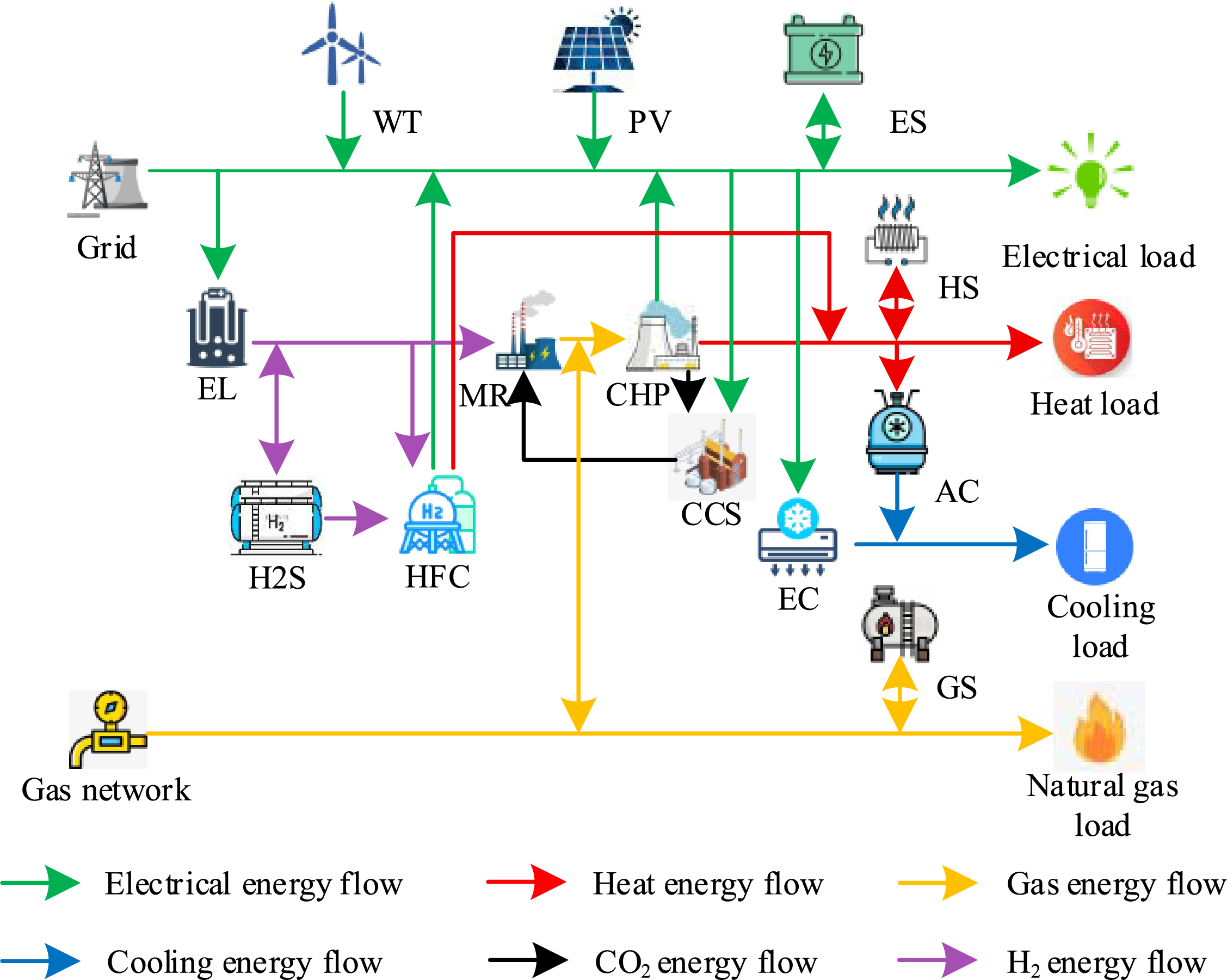
Figure 1: IES system diagram
2.1 P2G-CCS-HFC-CHP Coupling Mechanism
To achieve efficient coordination among multiple forms of energy and promote the cyclic utilization of carbon resources, this section systematically analyzes the coupling mechanisms of key devices including P2G, CCS, HFC, and CHP. On this basis, corresponding mathematical models are developed to support the subsequent system optimization and dispatch strategy.
(a) EL model
The EL serves as the central device that converts electrical energy into hydrogen by splitting water molecules, the corresponding mathematical formulation is presented in Eq. (1).
where,
(b) MR model
The MR converts hydrogen and CO2 into methane via catalytic reactions, thereby facilitating cross-energy carrier coupling between hydrogen and gas. The corresponding mathematical formulation is presented in Eq. (2).
where,
Carbon capture is a technology used to capture CO2 from exhaust gases produced by the combustion of fossil fuels.
where,
The HFC converts hydrogen power directly into electricity and heat through electrochemical reactions, offering advantages such as zero carbon emissions and rapid response. The corresponding mathematical model is presented in Eq. (4).
where,
Based on the aforementioned research, a coupled system integrating two-stage P2G, CCS, HFC, and CHP is constructed, forming the P2G-CCS-HFC-CHP (PCHC) integrated model. Fig. 2 depicts the operational behavior of the proposed PCHC system.
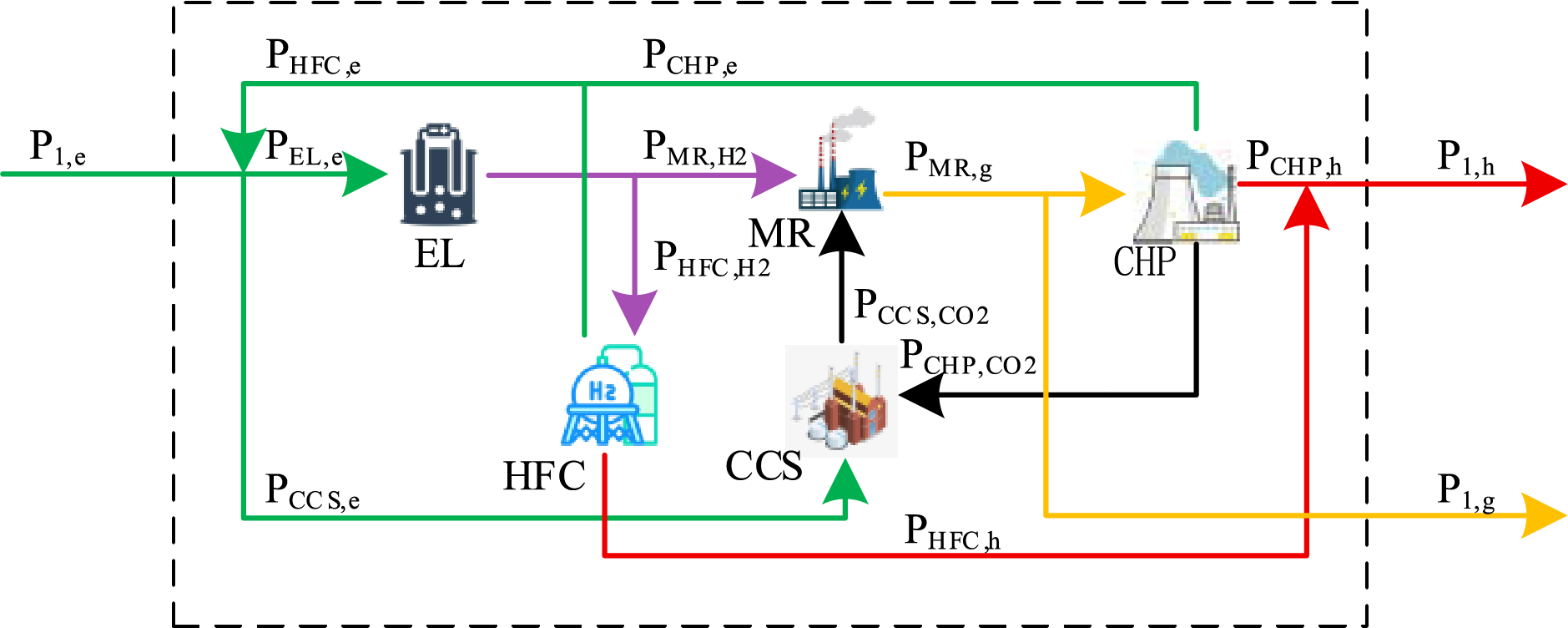
Figure 2: P2G-CCS-HFC-CHP coupled model
During joint operation, the P2G module utilizes surplus wind and solar power through the EL, with all hydrogen production sourced from EL. The generated hydrogen is primarily consumed by the MR and the HFC. Within the model, the PCHC system is treated as a unified coupled entity featuring three types of external energy interaction ports: electrical, thermal, and gaseous. These ports respectively fulfill the supply of electricity, heat, and gas energy. In this configuration, heat power is co-supplied by the HFC and the CHP unit, whereas methane is generated by the MR for either injection into subsequent energy applications.
Coupled model of electrical, gas and heat ports:
where,
The hydrogen energy boundary condition within the model is represented as follows:
where,
2.2 Ladder-Type Carbon Trading Costing Model
Regulatory agencies distribute initial carbon emission allowances based on the specific characteristics and origins of the emissions. When actual emissions surpass the allocated quota, the unit must acquire additional allowances from the carbon market, leading to increased expenses. Conversely, if emissions remain below the quota, the excess allowances can be sold, generating financial gains.
2.2.1 Carbon Credits Initial Quota Modeling
Within the IES, carbon emissions mainly stem from electricity imported from the upstream grid and the operation of CHP units. The model for the initial carbon emission allowance is given in Eq. (7).
where,
2.2.2 Net System Carbon Emissions
The integrated equipment configuration facilitates the capture of CO2 emissions generated by the CHP unit during its operation, thereby significantly reducing the total carbon emissions of the IES. The net carbon emissions of the system are defined in Eq. (8).
where,
2.2.3 Ladder-Type Carbon Trading Costing Model
To better reflect the cost constraints imposed by carbon markets on high-emission behavior, this study introduces a ladder-type carbon trading price mechanism. This mechanism divides the carbon allowance price into multiple segments, reflecting the rising marginal cost. The corresponding model is formulated in Eq. (9).
where,
where,
3 Low-Carbon Economic Optimization Model for IES
This study proposes an integrated modeling framework and coordinated operational strategy for the PCHC system, and further establishes a low-carbon economic dispatch model for the IES that incorporates market-based mechanisms and auxiliary energy supply. The objective is to minimize the total operating cost of the system by determining the optimal scheduling decisions.
3.1.1 Overall Operating Cost of the IES
The objective of the optimization model is to minimize the total operating cost of the IES, with its mathematical expression provided in Eq. (11).
where,
3.1.2 Systematic Acquisition of Energy and Penalty Costs
The system’s energy procurement and penalty costs encompass expenses related to electricity purchases from the upstream power grid, penalties incurred due to wind and solar curtailment, as well as ladder-type carbon trading costs determined by deviations from allocated carbon emission allowances. The corresponding mathematical expression is provided in Eq. (12).
where,
where,
where, respectively,
To achieve coordinated matching between energy supply and demand within the IES, it is essential to maintain energy balance across multiple forms—namely electricity, heat, cooling, and gas—at every time interval. This section delineates the energy balance constraints corresponding to electrical, thermal, cooling, and gaseous energies, this guarantees the feasibility of the scheduling plan and maintains uninterrupted energy flows.
3.2.1 System Electrical Balance Constraints
where,
3.2.2 System Heat Balance Constraints
where,
3.2.3 System Gas Balance Constraints
where,
3.2.4 System Cold Balance Constraints
where,
3.2.5 System Hydrogen Balance Constraints
where,
4.1 System Parameters and Scene Settings
A case study was conducted using data from an integrated energy park. Fig. 3 illustrates the forecasted profiles of wind and solar power, and electricity, heating, gas and cooling loads for a typical day.
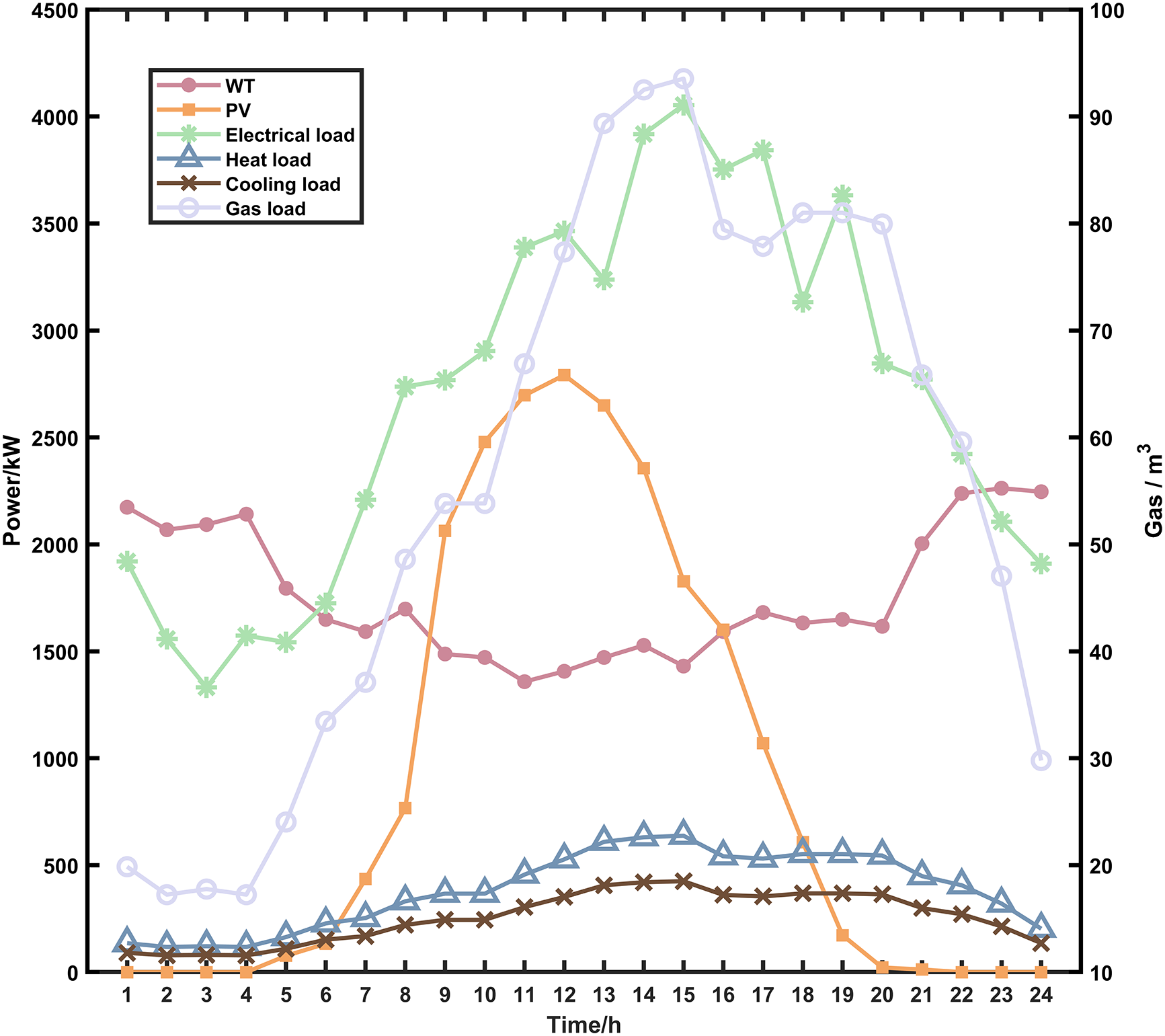
Figure 3: Power prediction curve
To assess the effectiveness of the proposed low-carbon economic dispatch model for the IES, this study establishes four sets of control cases for comparative analysis:
Scenario 1: Considering only CHP, without P2G, CCS, HFC and ladder-type carbon trading;
Scenario 2: Considering CHP, P2G, without CCS, HFC and ladder-type carbon trading;
Scenario 3: Considering the overall operation of CHP, P2G, CCS, HFC, without considering ladder-type carbon trading;
Scenario 4: Considering the overall operation of CHP, P2G, CCS, HFC, and considering ladder-type carbon trading.
4.2 Analysis of Optimized Scheduling Results for the IES under Various Scenarios
Scenario 1 relies entirely on CHP units for energy supply and requires substantial natural gas purchases, resulting in the highest energy procurement cost. Simultaneous to this, its new energy consumption capacity is extremely low, and curtailment of wind and solar energy remains a critical concern, and the related cost is also the highest. Scenario 2 introduces P2G device, which significantly enhances the wind and solar energy consumption rate by 39.1% compared with Scenario 1, and almost completely utilizes the excess wind and solar energy. Synthetic natural gas produced through P2G technology can be supplied to the system’s gas-consuming devices, which significantly lowers the cost of purchasing gas. However, neither Scenario 1 nor Scenario 2 includes carbon capture equipment; however, the CO2 produced by the system is released directly into the atmosphere. Although selling some synthetic natural gas brings revenue, the high cost of carbon tax seriously erodes the economic benefits.
Scenarios 3 and 4, on the other hand, adopt a multi-equipment coupled operation strategy, introducing carbon capture equipment with HFC, which significantly improves the IES’s efficiency by facilitating the coordinated use of renewable energy in combination with various energy carriers. This configuration not only captures the CO2 produced by the system and methanizes it through P2G, effectively reducing the system carbon emissions. The carbon tax expense in Scenario 3 decreases by 76.47% relative to Scenario 2, thereby easing the energy supply burden on the CHP unit and reducing the total system operating cost by 59.28%; the total purchased energy cost is reduced by about 80.13%. This optimization primarily stems from the effective carbon emission control enabled by CCS and the efficient hydrogen conversion and utilization facilitated by HFC. Together, these technologies enhance the internal energy circulation and conversion capabilities of the system, reducing reliance on external gas and power grids. These results demonstrate the significant advantages of adopting a low-carbon, high-efficiency operational strategy within an integrated energy system, achieving substantial renewable energy penetration alongside comprehensive and efficient energy utilization.
Building upon Scenario 3, Scenario 4 further incorporates a ladder-type carbon trading mechanism. As the price of carbon emission right allowances under this mechanism rises ladder-type with the increase in emissions, this creates a powerful driving force for lowering the system’s carbon emissions and promotes the advancement of carbon capture and sequestration technologies within the system. This further improves the overall operational efficiency of Scenario 4 and reduces the cost by another 16.29%, maximizing the net profit. In terms of economic efficiency, low-carbon operational performance, and renewable energy consumption capacity, Scenario 4 demonstrates notable advantages.
The economic dispatch outcomes across various scenarios are summarized in Table 2, while Fig. 4a depicts the corresponding renewable energy consumption rates. Scenario 4 attains a wind and solar consumption rate of 96.6%, slightly below that of Scenario 2; however, it achieves a substantial reduction in total operating costs by 65.4%. The carbon emission and absorption tracking results are presented in Fig. 4b, where the translucent area represents total system carbon emissions and the solid line denotes total carbon absorption. Notably, Scenario 4 demonstrates a great reduction in total carbon emissions compared to the other scenarios, achieving a 15.96% decrease relative to Scenario 3. This result highlights the effectiveness of implementing the ladder-type carbon trading mechanism in further constraining system-wide carbon emissions.
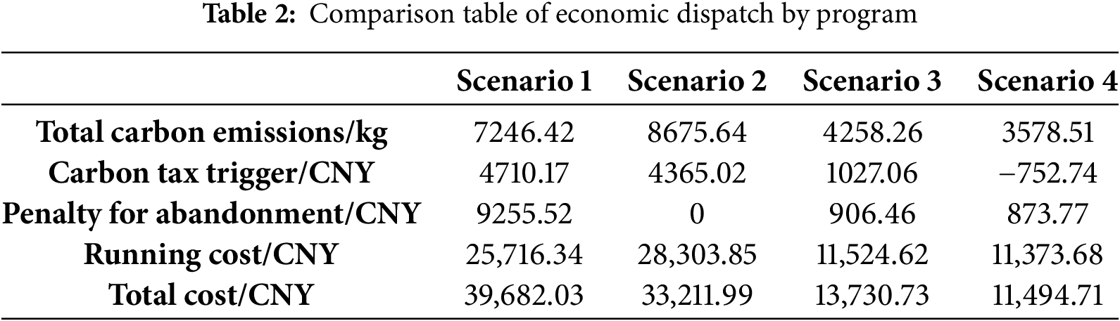
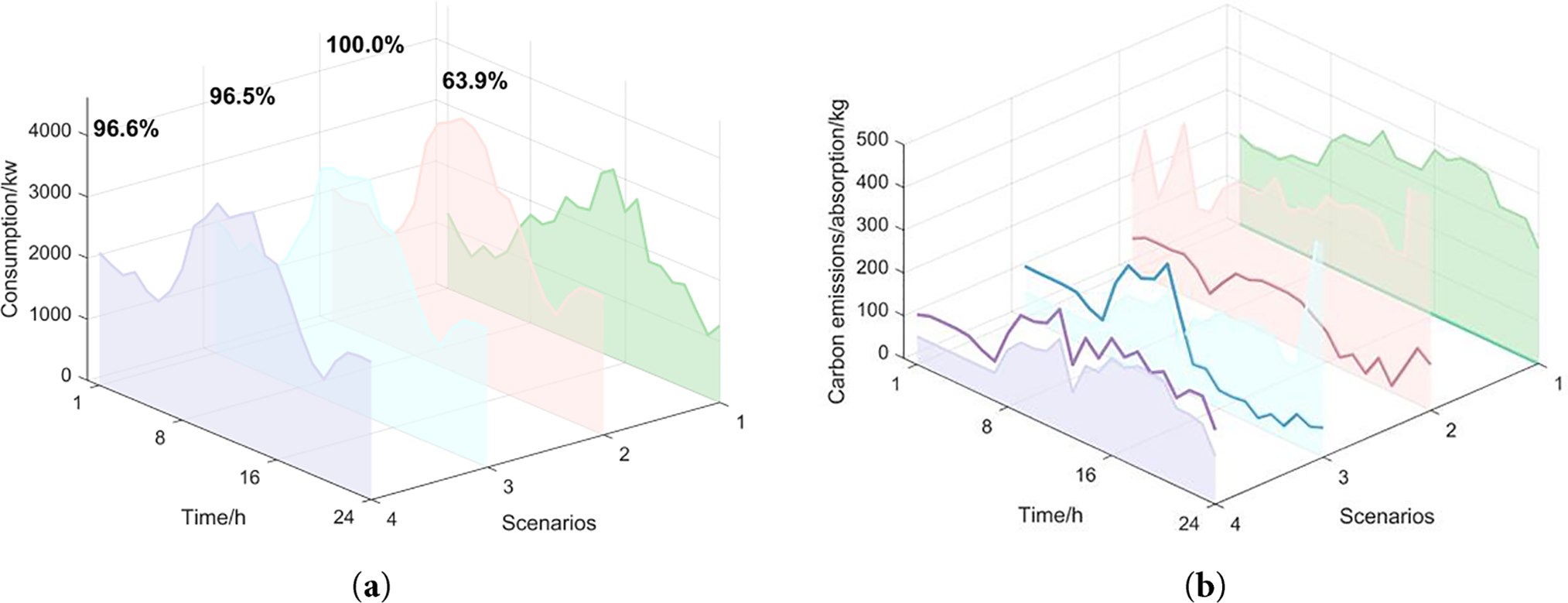
Figure 4: (a) Consumption of WT and PV; (b) Carbon tracking comparison
Throughout the operational period, the system consistently prioritizes the utilization of wind and solar energy generation, the system electrical balances illustrated in Fig. 5. During 7:00–12:00, the renewable energy output rises rapidly, the electrical load grows synchronously, and the electrolyzer fully consumes the surplus wind power to produce hydrogen. During 13:00–15:00, the cooling load peaks, and the electric chillers are activated to dissipate the electricity and reduce the pressure on the heating system, the system cooling energy balances illustrated in Fig. 6a. During 17:00–21:00, the renewable energy output trough is superimposed on the evening peak of electric load, CHP increases the power generation output, electrolyzer operates with reduced load, and the fuel cell calls for daytime hydrogen storage and generation to smooth out the load fluctuation. The fuel cell participates in system regulation on demand, supplementing the power gap throughout the day. EC cooperates with AC to optimize the energy consumption distribution during the cold load peak hours, and strengthens the efficiency of multi-energy flow coupling.
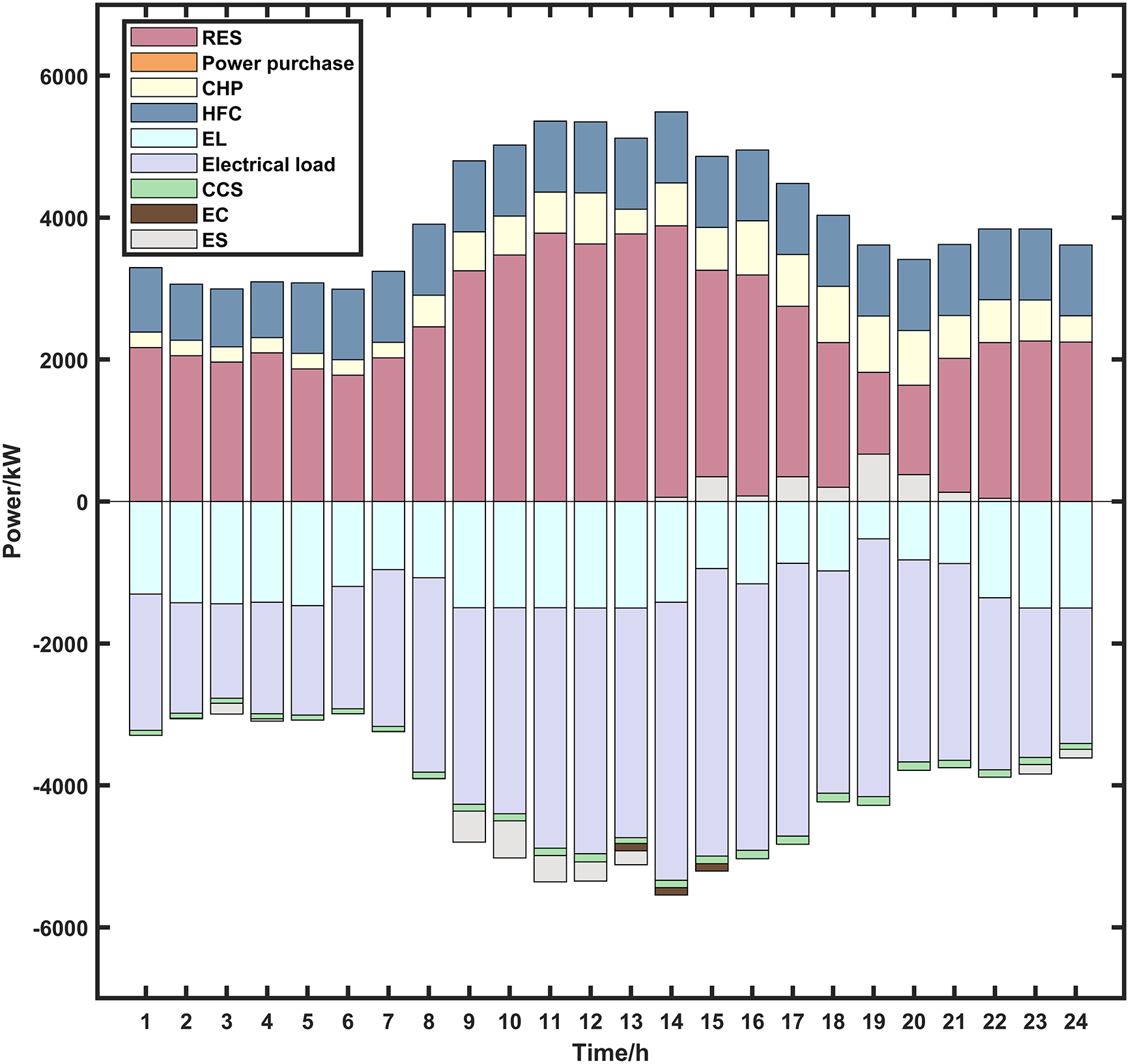
Figure 5: Power balance diagram
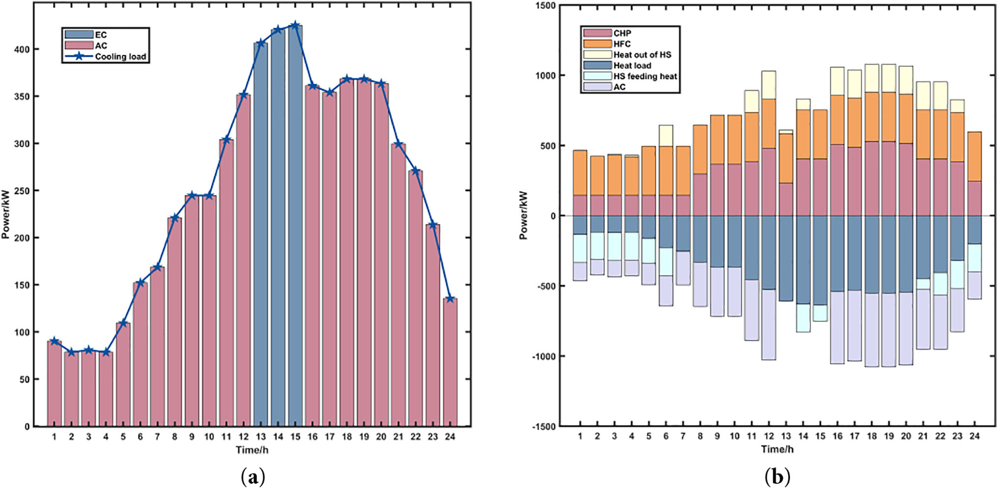
Figure 6: (a) Cooling energy balance diagram; (b) Heat balance diagram
For the heat load demand throughout the day, it is supplied by a combination of CHP and fuel cell, the system heat balances illustrated in Fig. 6b. During 0:00–6:00, the system heat load requirement is in the trough, CHP continues to stabilize the low output to decrease the operating cost, and HS stores the surplus heat energy. During 9:00–22:00, the heat and cooling load reaches the peak demand, CHP enhances the heat output to supply energy directly, and the heat storage unit releases the accumulated heat to support the energy supply during peak demand periods.
The daily gas load demand is predominantly met by the MR, with the system’s gas balance dynamics illustrated in Fig. 7a. From 00:00 to 07:00, both CHP output and gas load demand remain low, resulting in most of the gas produced by the MR being stored in GS. During the time interval between 08:00 and 23:00, the gas consumption by CHP and other loads gradually increases, and GS releases the previously stored gas to satisfy the rising energy demand. Between 17:00 and 21:00, a decline in renewable energy output causes a reduction in hydrogen production by the electrolyzer, leading to insufficient methane generation to meet the load requirements, the system hydrogen balances illustrated in Fig. 7b. Consequently, a small volume of gas is temporarily procured from the external gas network to compensate for short-term supply shortages.
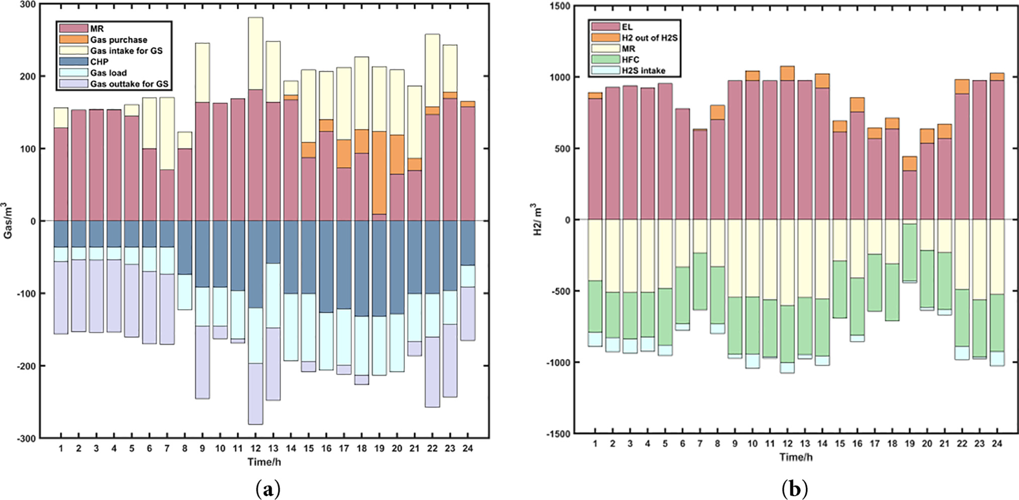
Figure 7: (a) Gas balance diagram; (b) Hydrogen balance diagram
4.3 Model Robustness Validation
To assess the model’s effectiveness in managing uncertainties in renewable energy generation, this study adopts a two-stage robust optimization approach specifically targeting the variability in wind and solar power outputs based on the methodology derived in [22], a typical min-max-min robust scheduling model is constructed to characterize the worst-case scenarios of wind and solar outputs. The system is then simulated under these worst-case conditions to assess performance. The final expressions of the master problem and subproblem are given by Eqs. (20) and (21).
where,
where,
The variations in wind and solar power generation are assumed to be bounded within a box-type uncertainty set
where,
The problem is addressed in this study using the Cut-and-Column Generation (C&CG) algorithm, which is implemented based on the Fig. 8.
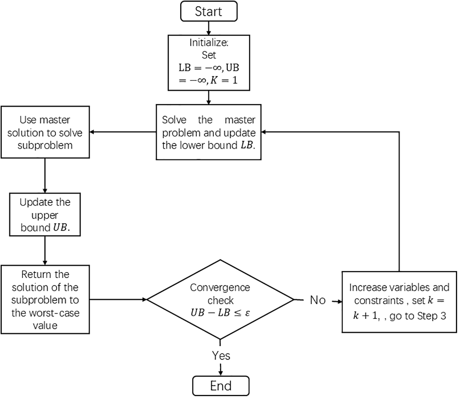
Figure 8: Solution process
The worst-case wind and solar output curves are constructed as shown in the Fig. 9. In this study, the fluctuation deviations for wind and solar output are considered to be 10% and 15% of their forecast values, respectively [23,24]. The shaded area in the figure represents the uncertainty set considered in this study. The worst-case wind and solar outputs are applied to Scenario 4, and the comparison of simulation outcomes is provided in Table 3.
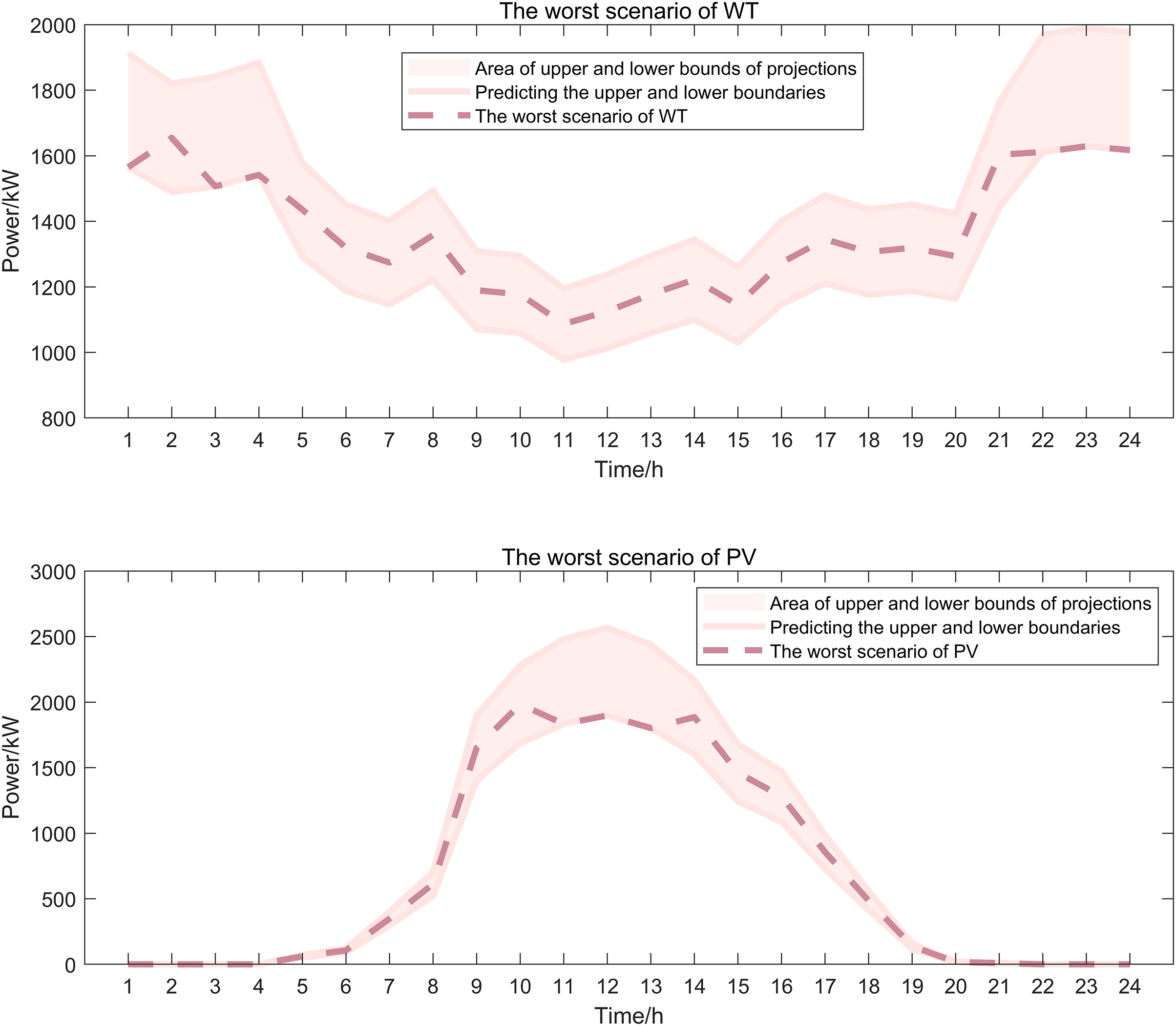
Figure 9: Worst-case scenarios for wind and solar
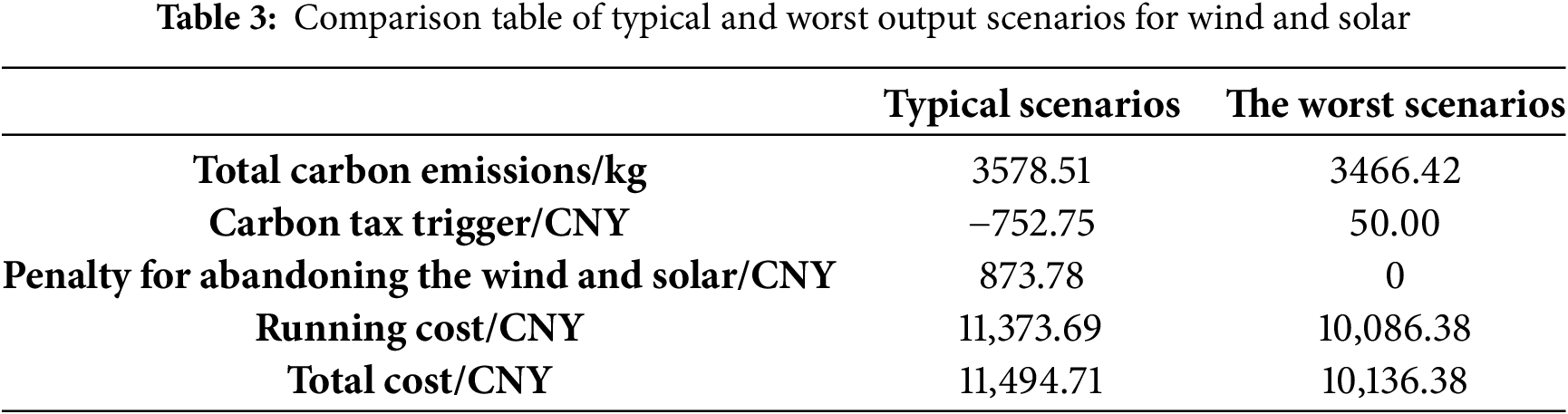
As shown in Table 3, under the worst-case scenarios of wind and solar power output, the system in Scenario 4 results in a reduced overall carbon footprint when compared to Scenario 3, while fully absorbing all wind and solar generation. However, due to insufficient renewable generation, supplemental gas must be procured from the external gas network. In summary, the implementation of Scenario 4 within the integrated energy system achieves reduced total operating costs, enhanced renewable energy consumption, improved carbon capture capacity, and a certain degree of operational robustness. Therefore, Scenario 4 represents the optimal solution for system optimization.
To promote efficient utilization of renewable resources, mitigate carbon emissions, and optimize the economic operation of integrated energy systems, this study proposes a low-carbon dispatch model that integrates multiple energy conversion devices and embeds a ladder-type carbon trading mechanism. Comparative analyses are conducted across various scenarios. Additionally, to validate the model’s robustness in handling uncertainty, a worst-case scenario of wind and solar power output is constructed for simulation testing. The following conclusions are derived.
This work introduces a two-stage hydrogen flow framework that separates the P2G process into electrolysis and hydrogen storage, with subsequent consumption via HFC. This closed-loop design explicitly models hydrogen efficiency and supports dynamic utilization within a unified dispatch model. As a result, hydrogen becomes a flexible buffer between electricity and gas sectors, contributing to a 39.1% increase in renewable energy utilization by mitigating intermittency and enhancing overall system flexibility.
A unified multi-energy optimization model is proposed that jointly coordinates P2G, CCS, HFC, and CHP under electricity–heat–cooling–gas coupling constraints. This holistic approach breaks the siloed modeling of past studies and enables deep synergy across sectors. The improved dispatch efficiency and flexibility lead to a 59.28% reduction in total operating costs, demonstrating the economic value of integrated low-carbon system optimization.
A ladder-type carbon pricing structure is integrated into the model to capture progressively increasing marginal penalties for emissions exceeding allocated limits. This design incentivizes internal carbon reduction rather than relying solely on external trading. The results demonstrate a 15.96% reduction in carbon emissions and a 16.29% decrease in operating costs, confirming the mechanism’s effectiveness in achieving both environmental and economic objectives.
Two-stage distributionally robust optimization model is developed to manage wind and solar power uncertainty using historical scenario-based data. The strategy identifies worst-case renewable outputs and ensures feasible operation across all system constraints. Numerical simulations confirm that the system maintains stable performance under these extreme conditions, validating its robustness and reliability in real-world applications dominated by renewable energy.
Acknowledgement: Not applicable.
Funding Statement: This research was supported by the Key Project of Shanghai (Project Number A1-0224-25-002-02-040, Municipal Key Course—Heat Transfer) and funded by the National Natural Science Foundation of China (Grant No. 52077137).
Author Contributions: Chenxuan Zhang conceived the idea, developed the methodology, clarified the underlying principles, and prepared the initial draft of the manuscript. Yongqing Qi supervised the project and approved the overall work. Ximin Cao contributed by reviewing, revising, and granting final approval of the manuscript. Yanchi Zhang offered technical guidance on data analysis and simulation validation. All authors reviewed the results and approved the final version of the manuscript.
Availability of Data and Materials: All data supporting the conclusions of this study are included within the article.
Ethics Approval: Not applicable.
Conflicts of Interest: The authors declare no conflicts of interest to report regarding the present study.
Nomenclature
| The total operating power of CCS at time t | |
| The fixed energy consumption of CCS | |
| The operating power of CCS at time t | |
| The electrical power consumed for capturing CO2 | |
| The carbon capture efficiency of CCS | |
| Carbon emission intensity per unit of power generation | |
| The maximum operating power of CCS | |
| Input the electrical energy of EL during period t | |
| The hydrogen energy output by EL during period t | |
| The energy conversion efficiency of EL | |
| Enter the upper limit of electrical energy of EL | |
| Input the lower limit of electrical energy of EL | |
| Input the hydrogen energy of MR during period t | |
| The natural gas power output by MR in period t | |
| Enter the upper limit of hydrogen energy for MR | |
| Input the lower limit of hydrogen energy for MR | |
| The power of HFC in the t period | |
| The electrical energy output by HFC during period t | |
| The thermal energy output by HFC during period t | |
| The efficiency of converting HFC into electrical energy | |
| The efficiency of converting HFC into thermal energy | |
| The upper limit of HFC power | |
| The lower limit of HFC power |
References
1. Pu Z, Yi T. Low-carbon economic energy sharing and revenue distribution strategy for multi-integrated energy systems considering the uncertainty of new energy output. Sustain Energy Grids Netw. 2025;43(10):101757. doi:10.1016/j.segan.2025.101757. [Google Scholar] [CrossRef]
2. Chen XQ, Yang LF, Dong W, Yang Q. Net-zero carbon emission oriented bi-level optimal capacity planning of integrated energy system considering carbon capture and hydrogen facilities. Renew Energy. 2024;237(Pt B):121624. doi:10.1016/j.renene.2024.121624. [Google Scholar] [CrossRef]
3. Chattopadhyay A, Witmer AP, Sauer PW. The need for teaching place-based contextualization for sustainable power system infrastructure design. IEEE Trans Power Syst. 2021;36(6):5846–53. doi:10.1109/TPWRS.2021.3079113. [Google Scholar] [CrossRef]
4. Sun CW, Tie Y, Yu LL. How to achieve both environmental protection and firm performance improvement: based on China’s carbon emissions trading (CET) policy. Energy Econ. 2024;130(5):107282. doi:10.1016/j.eneco.2023.107282. [Google Scholar] [CrossRef]
5. Sun P, Hao X, Wang J, Shen D, Tian L. Low-carbon economic operation for integrated energy system considering carbon trading mechanism. Energy Sci Eng. 2021;9(11):2064–78. doi:10.1002/ese3.982. [Google Scholar] [CrossRef]
6. Wang LY, Dong HQ, Lin JL, Zeng M. Multi-objective optimal scheduling model with IGDT method of integrated energy system considering ladder-type carbon trading mechanism. Int J Electr Power Energy Syst. 2022;143(S2):108386. doi:10.1016/j.ijepes.2022.108386. [Google Scholar] [CrossRef]
7. Jin J, Wen Q, Zhang X, Cheng S, Guo X. Economic emission dispatch for wind power integrated system with carbon trading mechanism. Energies. 2021;14(7):1870. doi:10.3390/en14071870. [Google Scholar] [CrossRef]
8. Li F, Wang D, Guo HD, Zhang JH. Distributionally robust optimization for integrated energy system accounting for refinement utilization of hydrogen andladder-type carbon trading mechanism. Appl Energy. 2024;367(4):123391. doi:10.1016/j.apenergy.2024.123391. [Google Scholar] [CrossRef]
9. Zhu X, Xue J, Hu M, Liu Z, Gao X. Low-carbon economy dispatching of integrated energy system with P2G-HGT coupling wind power absorption based on stepped Carbon emission trading. Energy Rep. 2023;10(34):1753–64. doi:10.1016/j.egyr.2023.08.023. [Google Scholar] [CrossRef]
10. Yang M, Liu Y. Research on multi-energy collaborative operation optimization of integrated energy system considering carbon trading and demand response. Energy. 2023;283:129117. doi:10.1016/j.energy.2023.129117. [Google Scholar] [CrossRef]
11. Li YB, Zhang F, Li Y, Wang YW. An improved two-stage robust optimization model for CCHP-P2G microgrid system considering multi-energy operation under wind power outputs uncertainties. Energy. 2021;223(9):120048. doi:10.1016/j.energy.2021.120048. [Google Scholar] [CrossRef]
12. Ma Y, Wang H, Hong F, Yang J, Chen Z, Cui H, et al. Modeling and optimization of combined heat and power with power-to-gas and carbon capture system in integrated energy system. Energy. 2021;236(5):121392. doi:10.1016/j.energy.2021.121392. [Google Scholar] [CrossRef]
13. Gao JW, Meng QC, Liu JT, Wang ZY. Thermoelectric optimization of integrated energy system considering wind-photovoltaic uncertainty, two-stage power-to-gas and ladder-type carbon trading. Renew Energy. 2024;221(2):119806. doi:10.1016/j.renene.2023.119806. [Google Scholar] [CrossRef]
14. He K, Zeng L, Yang J, Gong Y, Zhang Z, Chen K. Optimization strategy for low-carbon economy of integrated energy system considering carbon capture-two stage power-to-gas hydrogen coupling. Energies. 2024;17(13):3205. doi:10.3390/en17133205. [Google Scholar] [CrossRef]
15. Feng Z, Zhang J, Lu J, Zhang Z, Bai W, Ma L, et al. Low-carbon economic dispatch strategy for integrated energy systems under uncertainty counting CCS-P2G and concentrating solar power stations. Energy Eng. 2025;122(4):1531–60. doi:10.32604/ee.2025.060795. [Google Scholar] [CrossRef]
16. Jamal T, Shafiullah GM, Dawood F, Kaur A, Arif MT, Pugazhendhi R, et al. Fuelling the future: an in-depth review of recent trends, challenges and opportunities of hydrogen fuel cell for a sustainable hydrogen economy. Energy Rep. 2023;10(2):2103–27. doi:10.1016/j.egyr.2023.09.011. [Google Scholar] [CrossRef]
17. Wu QL, Li CX. Modeling and operation optimization of hydrogen-based integrated energy system with refined power-to-gas and carbon-capture-storage technologies under carbon trading. Energy. 2023;270(1–5):126832. doi:10.1016/j.energy.2023.126832. [Google Scholar] [CrossRef]
18. Wang M, Shi Z, Luo W, Sui Y, Wu D. Distributionally robust optimal scheduling of integrated energy systems including hydrogen fuel cells considering uncertainties. Energy Rep. 2023;10(4):1575–88. doi:10.1016/j.egyr.2023.08.056. [Google Scholar] [CrossRef]
19. Liu X. Optimal scheduling strategy of electricity-heat-hydrogen integrated energy system under different operating modes. Int J Energy Res. 2022;46(9):12901–25. doi:10.1002/er.8072. [Google Scholar] [CrossRef]
20. Zhang ZY, Wu YJ, Li XQ, Song MH, Zhang GW, Li ZW, et al. Optimization of supply and demand balancing in park-level energy systems considering comprehensive utilization of hydrogen under P2G-CCS coupling. Energy Eng. 2025;122(5):1919–48. doi:10.32604/ee.2025.063178. [Google Scholar] [CrossRef]
21. Li YM, Wang JJ, Cao YH. Multi-objective distributed robust cooperative optimization model of multiple integrated energy systems considering uncertainty of renewable energy and participation of electric vehicles. Sustain Cities Soc. 2024;104(2):105308. doi:10.1016/j.scs.2024.105308. [Google Scholar] [CrossRef]
22. Liu YX, Guo L, Wang CS. Microgrid two-stage robust optimal economic dispatch method. Proc CSEE. 2018;38(14):4013–22,4307. doi:10.13334/j.0258-8013.pcsee.170500. [Google Scholar] [CrossRef]
23. GB/T 19963.1-2021. China Electricity Council. In: Technical requirements for wind farm integration into power systems—part 1: onshore wind power. Beijing, China: China Standards Press; 2021. [Google Scholar]
24. GB/T 19964-2024. China Electricity Council. In: Technical requirements for photovoltaic power station integration into power systems. Bejing, China: China Standards Press; 2024. [Google Scholar]
Cite This Article
 Copyright © 2026 The Author(s). Published by Tech Science Press.
This work is licensed under a Creative Commons Attribution 4.0 International License , which permits unrestricted use, distribution, and reproduction in any medium, provided the original work is properly cited.
 Downloads
 Citation Tools