
 Login
Login Register
 Submit a Paper
 Propose a Special lssue
 Open Access
ARTICLE

Dynamic Modeling and Control of Phosphate-Pebble Drying Systems—A Comprehensive Approach
1 Electronic Engineering Department, Universitat Politècnica de Catalunya, Barcelona, Spain
2 Process Department, Celulosa Arauco y Constitución SA, Concepción, Chile
3 Process Research Department, Celulosa Bioforest SA, Concepción, Chile
* Corresponding Author: José M. Campos-Salazar. Email:
Energy Engineering 2026, 123(6), 14 https://doi.org/10.32604/ee.2026.075407
Received 31 October 2025; Accepted 20 March 2026; Issue published 27 May 2026
 View Full Text
 Download PDF
Abstract
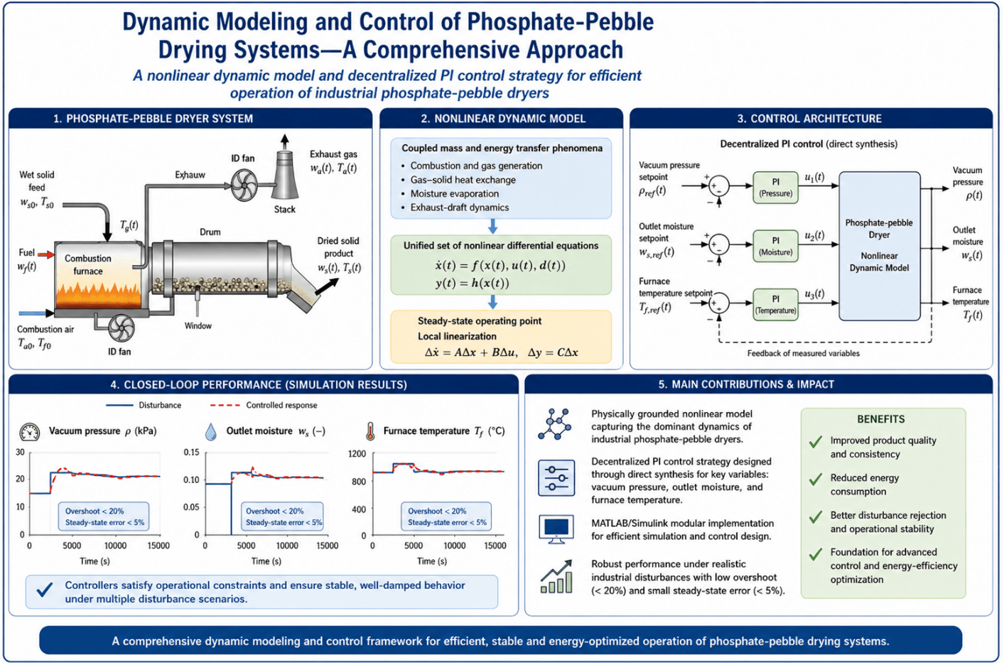
A nonlinear dynamic framework is developed to represent the coupled mass- and energy-transfer phenomena governing an industrial phosphate-pebble dryer. The formulation integrates combustion, gas–solid heat exchange, moisture evaporation, and exhaust-draft dynamics into a unified set of nonlinear differential equations suitable for transient analysis and control design. Steady-state operating conditions are first established, followed by local linearization to enable the synthesis of decentralized proportional–integral (PI) controllers using direct-synthesis principles. The resulting control architecture regulates key process variables, including vacuum pressure, outlet moisture content, and furnace temperature. The proposed model is implemented in MATLAB/Simulink using a modular structure that preserves the physical interpretation of each subsystem while enabling efficient numerical simulation. Closed-loop performance is evaluated under multiple disturbance scenarios, including variations in pressure, feed moisture, temperature, and flow conditions representative of industrial operation. Simulation results demonstrate that the designed controllers satisfy operational constraints, achieving overshoot values below 20% and steady-state errors under 5% across all regulated variables. The responses exhibit stable and well-damped behavior, confirming the suitability of the control-oriented modeling approach for capturing dominant process dynamics. The resulting framework provides a physically grounded and computationally efficient representation that supports dynamic performance assessment, disturbance rejection analysis, and future extensions toward advanced control strategies and energy-efficiency optimization.Graphic Abstract
Keywords
Drying operations are fundamental, yet energy-intensive unit processes extensively deployed across chemical, mineral, and agri-food industries. In the context of phosphate fertilizer production, mined phosphate “pebbles” must undergo thermal dehydration to reduce their inherent moisture content prior to acidulation and downstream processing. This drying step is driven by two pivotal industrial objectives: (i) minimizing the transport of excess water, which translates to reduced logistical costs, and (ii) improving the flowability, grindability, and overall handling characteristics of the solid feedstock [1]. Industrial phosphate dryers are typically large-scale rotary drums wherein the wet solids are exposed to high-temperature combustion gases, facilitating concurrent convective heat and mass transfer. These systems exhibit complex nonlinear dynamics arising from the interaction between thermal and moisture transport phenomena, spatial and temporal transport delays, and the coupled behavior of the gas and solid phases. Consequently, accurate dynamic modeling is essential not only for process design and optimization but also for control synthesis aimed at maintaining product quality and energy efficiency under transient conditions; recent research increasingly emphasizes control-oriented modeling of rotary dryers for operational flexibility and energy-management objectives [2].
Indeed, other advances in drying system research have increasingly emphasized the development of dynamic and control-oriented models capable of capturing transient behavior under variable operating conditions. In particular, modern studies have explored energy-efficient operation, flexible process control, and improved system responsiveness through physics-based and hybrid modeling approaches [3–6]. These contributions highlight the growing need for models that not only describe steady-state performance but also enable real-time optimization and advanced control implementation in large-scale industrial dryers.
Several modeling paradigms have been developed to represent drying systems, ranging from empirical correlations and black-box system identification to high-fidelity first-principles and computational fluid dynamics (CFD) approaches. Recent reviews highlight sustained growth in dryer modeling and optimization methods (including hybrid physics/data-driven approaches and parameter-optimization strategies) across multiple dryer types and industrial contexts [7]. Empirical thin-layer models, such as the Newton, Page, and Henderson–Pabis formulations [8], remain widely used in laboratory-scale studies owing to their simplicity and ease of parameterization. While these models capture moisture-removal trends over time using one or more adjustable parameters, their reliance on curve-fitting techniques and limited physical insight renders them unsuitable for extrapolation beyond calibrated operating conditions. Despite these limitations, they continue to be cited in the literature for a wide variety of agricultural and food products due to their minimal data requirements and acceptable predictive accuracy under fixed settings [8].
More recent developments have extended traditional modeling approaches by incorporating enhanced heat and mass transfer descriptions, as well as improved representation of variable operating conditions. These models often integrate energy analysis, parameter sensitivity, and system-level optimization to better capture industrial dryer performance [4,5,9]. Such approaches provide a more robust framework for analyzing process efficiency and dynamic behavior, particularly in large-scale systems where operating conditions may vary significantly over time.
In contrast, black-box system identification and machine-learning-based techniques have gained traction for modeling complex drying systems where first-principles derivation is challenging. Approaches including ARX/ARMAX models, support vector regression, and adaptive neuro-fuzzy inference systems have been applied to rotary dryers with promising accuracy [10,11]. However, the predictive capability of these models is typically confined to the training domain, and their interpretability is inherently limited. Consequently, such models are often integrated with physics-based approaches when control-oriented modeling is required, as also reflected in recent surveys of drying-parameter optimization and modeling trends [7].
CFD offers a high-resolution alternative for simulating coupled heat, momentum, and species transport within dryers. State-of-the-art studies employ multiphysics CFD solvers coupled with discrete element methods (DEM) to resolve solid–gas interactions in packed beds or rotary drums [12]. Examples include the 3D modeling of iron ore pellet dryers and the simulation of laboratory-scale rotary kilns incorporating radiation and detailed kinetics [5,13]. Complementary recent work illustrates the role of bed-scale transport non-uniformities in packed-bed drying simulations [14] and the use of DEM-informed reduced representations to capture solids motion and residence effects in rotary fertilizer drying [15]. These studies provide deep insight into localized phenomena such as velocity fields, temperature gradients, and internal diffusion. However, the computational expense, complexity of mesh generation, and parameter calibration significantly limit the practicality of CFD for dynamic control studies or real-time applications.
In parallel, recent studies have investigated reduced-order and control-oriented representations derived from high-fidelity models, aiming to balance computational efficiency with physical accuracy. These approaches enable the integration of advanced control strategies, including multivariable and model-based control techniques, which are increasingly applied to drying systems to enhance stability, disturbance rejection, and energy efficiency [6,16]. This trend reflects a shift toward models that are not only descriptive but also directly applicable to control system design.
To bridge the gap between empirical simplicity and CFD detail, first-principles dynamic models based on conservation laws (mass, energy) have emerged as an effective compromise. These models offer physically grounded formulations capable of capturing drying kinetics, gas–solid heat exchange, and internal moisture transport, often with reduced computational burden. The literature documents several seminal contributions in this area, such as the lumped and distributed models for rotary dryers developed in [17–19], which laid the foundation for simulating transient drying behavior under various operating scenarios. More recent contributions increasingly emphasize explicitly control-oriented formulations for rotary dryers (including structures suitable for linearization and controller synthesis) [2], as well as hybrid reduced-order strategies informed by solids-motion modeling [15]. In addition, dynamic models validated against semi-industrial dryers for citrus residues and soybean seeds [20,21], confirming the utility of this approach in both simulation and control design. Notably, such models yield systems of ordinary or partial differential equations that can be linearized for model-based controller synthesis.
Furthermore, recent literature has highlighted the importance of advanced control strategies in industrial drying applications, particularly under nonlinear and multivariable conditions. Techniques such as model predictive control, adaptive control, and optimization-based approaches have demonstrated significant improvements in energy utilization and product quality when supported by accurate dynamic models [6,16]. However, the successful application of these strategies strongly depends on the availability of physically consistent and control-oriented models capable of representing the dominant process interactions.
Despite the maturity of drying-system modeling in general, a critical knowledge gap exists regarding phosphate pebble drying systems. Specifically, no existing study reports a comprehensive dynamic model encompassing the full process—from combustion and hot gas generation to the drying systems and exhaust subsystems—for phosphate pebbles dryers. This is surprising given the unique characteristics of phosphate drying: dense, heterogeneous solids with high thermal inertia and internal moisture gradients, large flow rates, and dusty exhaust environments. Recent work has demonstrated that multivariate industrial drying processes can be modeled and experimentally validated when plant data are available [22], yet prior works relevant to phosphate operations have often been steady-state in nature or partial in scope, focusing on isolated subsystems such as the furnace or airflow control [11,22]. This lack of a unified model hinders the development of effective control strategies for energy efficiency and product quality in phosphate drying operations.
The present study addresses this deficiency by introducing a novel nonlinear dynamic model of an industrial phosphate-pebble drying system. The model is formulated from first principles and integrates all critical components: (i) the combustion subsystem (fuel and air mixing, burner dynamics), (ii) the drying system (with gas–solid energy and mass balances), and (iii) the exhaust gas handling unit (including stack flow and draft pressure).
The resulting model comprises a coupled set of nonlinear differential equations, capturing the dynamic propagation of disturbances through the system.
Building on this model, the study further develops a multivariable control strategy using decentralized PI compensators tuned via the direct synthesis method (DSM). The linearized model around a nominal operating point facilitates the derivation of decoupled controllers with targeted performance metrics.
Simulation results under multiple disturbance scenarios demonstrate superior setpoint tracking, reduced overshoot, and robust disturbance rejection—highlighting the efficacy of the proposed control approach relative to conventional tuning heuristics.
In summary, this article makes two primary contributions. First, it develops the first comprehensive, first-principles dynamic model of an industrial phosphate-pebble drying system, explicitly integrating the combustion, drying, and exhaust subsystems within a unified thermodynamic and hydrodynamic framework. Second, the model is exercised through a set of representative closed-loop simulations using DSM-tuned PI controllers, not with the intention of establishing control superiority, but rather to demonstrate that the nonlinear model reproduces realistic dynamic interactions, disturbance propagation, and regulatory behavior. The control design therefore serves as a proof-of-concept validation stage, illustrating how the model can support future controller benchmarking and process optimization studies.
It is important to clarify that the present work constitutes a proof-of-concept dynamic modeling study, as no industrial phosphate-pebble dryer was accessible for data collection. Consequently, the model is not experimentally validated against plant measurements, and no calibration using moisture, temperature, or flow datasets was possible. Instead, the model has been validated in a structural and internal-consistency sense, ensuring that the mass and energy balances close, that state trajectories remain physically consistent, and that transient responses behave in accordance with established drying theory. The control simulations included in this work should therefore be interpreted as a demonstration of model coherence, not as performance predictions for any specific industrial dryer. A full experimental validation—requiring facility access, instrumentation deployment, and test-campaign planning—is identified as future work once industrial collaboration becomes available, consistent with recent practice in experimentally validated industrial drying studies [22].
The remainder of the paper is organized as follows. Section 2 outlines the industrial phosphate dryer system. Section 3 details the dynamic model formulation. Section 4 presents dryer efficiency expression. Section 5 describes the control strategy and tuning. Section 6 discusses simulation results, and Section 7 concludes the study.
Fig. 1 shows a simplified process flow diagram of the phosphate-pebble dryer. The system is composed of four primary subsystems: (i) the combustion furnace, (ii) the windbox, (iii) the drying zone (pebble bed), and (iv) the exhaust stack. Each subsystem functions as a thermodynamic control volume governed by transient mass, energy, and momentum balances. Together, these subsystems convert the chemical energy of the fuel into sensible heat, transfer that heat into the solid pebbles, and remove the evaporated moisture from the phosphate matrix.

Figure 1: Phosphate-pebble drying systems. Process diagram.
The combustion furnace is the primary source of thermal energy in the dryer. It receives two inlet streams:
• Fuel stream (wf(t))—typically a flow of oil or natural gas delivered by a pump.
• Combustion air stream (fa(t))—air supplied by a forced-draft fan (FD fan) to support combustion.
It is important to highlight that variations in the fuel pump and forced-draft fan speeds are achieved through modulation of their respective control signals, kCf(t) and kCa(t), which directly govern the fuel and air flow rates into the combustion furnace.
Within the furnace, the fuel and air mix and undergo complete combustion, converting the fuel’s chemical energy into hot flue gases. The flue gas composition is primarily nitrogen, carbon dioxide, and water vapor from combustion. The furnace operates at high temperatures (roughly 900°C–1200°C) to provide a strong driving force for downstream heat transfer. The hot flue gases are then directed as the outlet stream from the furnace into the next stage (the windbox). The furnace is designed for stable combustion with minimal excess oxygen and thorough mixing of air and fuel to ensure consistent operation [23–25].
The windbox is a plenum chamber (pressurized box) between the furnace and the drying zone. Its purpose is to equalize pressure fluctuations, stabilize the flow, and uniformly distribute the combustion gases across the pebble bed. In doing so, it ensures the drying zone receives a steady, evenly distributed supply of hot gas.
Hot flue gas from the furnace enters the windbox at a high temperature and may be conditioned (i.e., mixed with additional air) before reaching the pebble bed. The windbox outputs a hot gas stream at temperature Td(t), which serves as the inlet gas condition for the drying zone. Any additional air introduced at this stage can be used to fine-tune the oxygen content or adjust the gas temperature as needed. A well-designed windbox provides even gas distribution, preventing flow channeling (preferential pathways) or other non-uniformities that would cause uneven drying across the bed [26–28].
The drying zone is the core of the process, containing a fixed bed of phosphate pebbles through which the hot combustion gases flow. Two major mass streams define this subsystem:
• Wet pebble feed: Incoming pebbles enter the dryer at a mass flow rate ws(t), with an inlet moisture fraction xin(t) (approximately the weight fraction of water in the feed).
• Dried pebble product: Pebbles exit the dryer at the same mass flow rate ws(t) (assuming no solids loss), but with a reduced moisture content xout(t) after drying.
• Within this zone, moisture is removed from the pebbles through two principal mechanisms:
• Convective heating: Hot gases convectively transfer thermal energy to the pebble surface, increasing the solid temperature.
• Evaporation: Moisture within the pores and on the surface of the pebbles is vaporized, consuming latent heat associated with the phase change.
The bed geometry and uniform airflow distribution are designed to enhance gas–solid contact, thereby maximizing the efficiency of both heat and mass transfer. The dried solids leaving this zone constitute the main product stream, and the outlet moisture fraction xout(t) serves as a key quality indicator of the drying process. This zone also represents the primary site of dynamic variability, as disturbances such as fluctuations in feed moisture or solids throughput must be effectively mitigated by control actions to ensure consistent product quality and process stability [29–32].
It is also worth noting that the pebble bed within the dryer is mechanically conveyed by a drive system, actuated by an electric motor controlled via a variable frequency drive (VFD). This VFD, in turn, is modulated by the control signal kCs(t), which governs the bed’s movement dynamics.
It is important to note that, for the sake of model tractability and clarity, radiative heat transfer mechanisms have not been included in the present formulation. Although radiation may contribute under certain high-temperature conditions, its effect is often secondary in gas–solid systems dominated by convective and evaporative phenomena, particularly in fluidized or well-mixed beds. This assumption aligns with prior modeling practices where the primary focus is on dominant convective and latent heat pathways [12].
2.4 Exhaust Stack and Induced-Draft Fan
The exhaust system removes the moisture-laden exhaust gases from the dryer and safely releases them to the atmosphere. The gas stream leaving the pebble bed contains the combustion products plus the evaporated water vapor from drying. An induced-draft fan (ID fan) draws this hot, humid stream out through the exhaust stack. The ID fan serves two critical roles:
• Maintain negative pressure: It maintains a slight negative pressure (vacuum) inside the dryer to prevent any backflow of gases into the upstream equipment.
• Regulate exhaust flow: It regulates the exhaust flow rate wstack(t), which in turn controls the residence time of gases in the system and thus influences the drying efficiency.
The exhaust stream is typically monitored by measuring the stack gas temperature (Tstack(t)) and pressure (p(t)), both of which are key indicators used for process monitoring and control. In some systems, the stack may be equipped with heat-recovery units (to reclaim energy) or pollution-control devices (to scrub or filter emissions). However, the primary function of the exhaust stack is the safe discharge of the spent gases to the environment [33–35].
The phosphate-pebble drying process involves four interconnected subsystems: the combustion furnace, the windbox, the drying zone, and the exhaust system. Each subsystem is modeled as a thermodynamic control volume governed by transient mass and energy balances, assuming ideal gas behavior and spatial homogeneity (i.e., perfectly mixed temperatures and compositions). The model is designed to capture the dominant dynamics of heat and mass transfer while maintaining simplicity and tractability. To that end, several assumptions are adopted: combustion is complete and instantaneous, moisture is evenly distributed within the pebbles, and the only heat transfer mechanism explicitly considered is convection. Radiative effects, while potentially significant at high temperatures, are excluded in this formulation for clarity and consistency with similar models in the literature [12].
The process begins with wet phosphate pebbles entering the drying zone at mass flow rate ws(t) and inlet moisture fraction xin(t). Hot combustion gases generated in the furnace—by mixing a fuel flow wf(t) with combustion air fa(t)—are supplied via a forced-draft fan and flow through the windbox before reaching the drying zone at temperature Td(t). Within the bed, the solid phase is modeled with a time-varying dry mass ms(t), a time-varying water mass mwt(t), and temperature Ts(t). The outlet moisture fraction xout(t) is defined by the following:
The drying zone energy balance includes convective heat transfer from the gas stream to the solids, moisture evaporation consuming latent heat, and sensible heating of the pebble matrix. Evaporated moisture joins the gas phase, which exits the bed at mass flow rate wg(t) and temperature Tg(t). The outlet solids, exiting with the same flow ws(t), define the process product.
The exhaust subsystem receives the hot, humid gases and directs them through an induced-draft fan to the stack. The fan regulates the exhaust flow wstack(t) and maintains the internal dryer pressure p(t). The mole balance within the exhaust is governed by the ideal gas law, relating molar density, pressure, and volume. An energy balance is applied to the exhaust volume, including sensible heat of the flowing gases and their pressure–temperature evolution.
Three key feedback control loops are integrated into the system. The primary loop regulates xout(t) by manipulating the pebble feed rate ws(t). The second loop stabilizes the dryer’s internal pressure p(t) via the ID fan. The third loop controls the gas temperature Tw(t) at the windbox inlet by adjusting the furnace fuel/air ratio. These loops collectively ensure efficient, stable, and high-quality drying performance under dynamic operating conditions.
3.1 Combustion Furnace Modeling
The combustion furnace is modeled as a lumped thermodynamic control volume where fuel and air are continuously mixed and combusted to generate hot flue gases. The system receives two input streams: a mass flow of fuel wf(t) in kg/s, regulated by a dedicated pump via a command signal kCf(t), and a volumetric airflow fa(t) in m3/s, provided by a forced-draft fan and modulated through kCa(t). The combustion process is assumed to be complete and instantaneous, with ideal gas behavior and a uniform gas composition throughout the chamber.
The resulting output stream is the hot gas flow ww(t) in kg/s, leaving the furnace at temperature Tw(t) in K, and feeding into the windbox. The total gas mass within the furnace is denoted by mc(t) in kg.
The dynamic mass balance is written as:
where ρa is the air density in kg/m3.
The corresponding energy balance, assuming negligible heat losses (adiabatic system), is given by (3). Here, Ta(t) and Tw(t) are the temperatures of the incoming air and outgoing combustion gases, respectively, both in K, cpa is the specific heat of air at constant pressure in kJ/kg·K, cpc, cvc are the specific heats of the combustion gases at constant pressure and volume, respectively, in kJ/kg·K, and finally, HV is the heating value of the fuel in kJ/kg.
Eqs. (2) and (3) constitute a zero-dimensional dynamic model of the furnace, capturing the unsteady accumulation of mass and energy. Under the common isobaric assumption (valid for systems with pressure control via the FD-fan), the fuel heating value directly appears as enthalpy input. The outflow ww(t) then serves as the hot gas input to the windbox stage in the downstream dryer system. This modeling approach follows established practices for high-temperature combustion systems [36].
The windbox acts as an intermediate plenum that receives hot combustion gases from the furnace and delivers them uniformly to the drying zone. It serves as a stabilizing volume, ensuring that the temperature and pressure of the incoming gas flow are well mixed before reaching the pebble bed. In this system, the windbox is modeled as a lumped control volume with one inlet and one outlet.
The inlet is the gas stream from the combustion furnace, with mass flow rate ww(t) in kg/s and temperature Tw(t) in K. The outlet is the gas stream directed toward the drying zone, with mass flow rate wd(t) in kg/s and temperature Td(t) in K. The total mass of gas contained within the windbox is denoted by mw(t) in kg.
Assuming no gas is lost within the windbox and no additional air is injected, the dynamic mass balance is given by:
The corresponding energy balance assumes adiabatic conditions (i.e., negligible heat losses), and uniform mixing of gases within the chamber:
here, cpc is the specific heat of the combustion gases entering the windbox in kJ/kg·K, cpd, cvd are the specific heats of the windbox gas mixture at constant pressure and volume, respectively in kJ/kg·K, Tw(t) is the furnace gas temperature at the windbox inlet in K, and finally, Td(t) is the gas temperature exiting toward the drying zone in K.
This lumped formulation captures the dynamic accumulation of both mass and energy inside the windbox, allowing transient variations in fuel or air flow from the furnace to influence the gas temperature supplied to the dryer. In many cases, the temperatures Tw(t) and Td(t) are close, due to the short residence time and good mixing within the windbox. This modeling approach is consistent with previous drying and furnace systems described in the literature [37].
The dryer is the core component of the phosphate pebble drying process. It has two input streams and two output streams. The first input is the mass flow of phosphate pebbles, denoted by ws(t) in kg/s, which moves through a mechanically driven bed. This bed is powered by a motor via a frequency converter drive, whose control signal is given by kCs(t). The pebble flow is composed of two components: a dry solid mass ms(t) in kg and an entrained water mass mwt(t), also in kg. The feed enters the dryer at an inlet temperature Tsin(t) in K and an initial moisture content xin(t) (expressed on a wet basis).
The second input stream is the hot gas flow wd(t) in kg/s entering from the windbox at temperature Td(t), also in K. These gases transfer heat to the solids to evaporate moisture.
The two output streams are:
• The dried pebble flow, which exits at the same mass rate ws(t) but with a reduced moisture fraction xout(t). It is assumed that there is no solids buildup or loss.
• The outgoing gas flow wg(t) in kg/s, which carries the evaporated moisture and exits at temperature Tg(t) in K.
Assuming no accumulation of dry solids in the bed [18]:
This implies the dry mass flow into and out of the dryer remains equal. For the water content in the pebbles, the balance is:
This equation tracks the change in water mass due to drying.
A relation between the outlet moisture content and the internal masses is given by:
This reflects the wet-basis definition of moisture content.
Assuming the bed has a uniform temperature and that radiation is negligible, the energy balance becomes in (9) [18]. From here, here, cvs, cps are the specific heat of dry solids at constant pressure and volume, respectively, in kJ/kg·K; cvwt is the specific heat of entrained water at constant volume in kJ/kg·K; cpd is the specific heat of incoming drying gases, in kJ/kg·K; cpg is the specific heat of gases leaving the dryer at constant pressure, also in kJ/kg·K. On the other hand, λd is the latent heat of vaporization of water measures in kJ/kg; U in the overall heat transfer coefficient measures in kW/m2·K, and finally, A is the effective heat transfer area in m2.
This expression assumes perfect mixing, negligible heat losses, constant physical properties, and ideal gas behavior where applicable. The gas temperature Tg(t) dynamically changes based on heat exchange, evaporation, and outlet losses.
The gas stream wg(t) serves as the coupling variable between the dryer and the next stage (exhaust system.) [18].
The exhaust system is the final subsystem of the phosphate pebble drying process. It connects the dryer to the stack and enables the removal of moisture-laden combustion gases. The system consists of a single inlet and a single outlet stream.
The inlet stream is the gas flow exiting the dryer, denoted as wg(t) in kg/s, at a temperature Tg(t) measures in K. The outlet stream corresponds to the flue gas flow directed toward the stack, labeled wstack(t) in kg/s, with an associated temperature Tstack(t) in K. This outlet flow is driven by the ID-fan, which establishes the necessary pressure differential. The fan is regulated by a control signal kCd(t), normalized to unit scale. Internally, the exhaust system is pressurized to p(t) measures in kPa.
To describe the system dynamics, a mole balance is formulated based on the ideal gas behavior assumption (valid under low-pressure operation). First, the mole balance is expressed as:
where n(t) is the number of moles of gas in kmol and
It can be assumed that the pressure p(t) is relatively low, so it is possible to use the ideal gas equation, that is,
where R is the universal gas constant, measures in kJ/kmol·K and V is the gas volume, in m3.
Substituting (11) into (10), the pressure dynamics is obtained, as follows:
Developing (12), the material balance associated with the exhaust system is obtained, which is defined as:
Finally, the energy balance for the exhaust system is described as follows:
here, cx denotes specific heat capacities: cpg is for gases entering from the dryer at constant pressure, while cpstack and cvstack are for the gases exiting to the stack at constant pressure and volume, respectively, all in kJ/kg·K. ρstack is the mass density of the exhaust gases in kg/m3.
Thus, Eqs. (1)–(14) collectively define the full nonlinear and coupled dynamic model governing the behavior of the phosphate pebble drying system.
To develop a linearized model of the phosphate pebble dryer, it is first necessary to determine the system’s steady-state operating points (OPs). These OPs represent constant values of all process variables where the system remains in equilibrium. Linearization is then carried out around these points to approximate the system’s behavior under small deviations, ensuring the linear model accurately captures local dynamics near the steady state [38].
By setting all time derivatives in the dynamic Eqs. (1)–(14) to zero, the original system of nonlinear differential equations is reduced to a set of algebraic equations. These equations represent the steady-state mass and energy balances for each subsystem. Variables under steady-state conditions are denoted with the superscript “ss.” The complete system is given in Appendix A as equation set (A1).
To solve this system, two variable groups are defined: the known variable vector (kv) and the unknown variable vector (uv). For this study, the known variables are: kv = [wfss, wsss, fass, kCfss, kCass, kCsss, kCdss, Twss, Tass, Tsinss, xinss, xoutss, pss] and the unknowns are: uv = [wwss, wdss, wgss, Tdss, Tgss, Tstackss].
Solving equation set (A1) with the given kv allows us to compute the values in uv, as detailed in (A2). In symbolic terms, kv ∈ {ℝ13} and uv ∈ {ℝ6}.
3.6 Linear Model in State Space
Once the OPs have been calculated, it is possible to perform the linearization process on the nonlinear model described by (1)–(14). Using the Taylor series expansion and perturbation technique, the model is linearized [38,39]. From this process, the linear model in state space of the system is obtained, as a function of the deviation variables (dv), which is described as:
In simple terms, the dvs are defined as xdv(t) = x(t) − Xss. By definition, xdv(t) represents the instantaneous perturbation from steady state. Under the small-signal assumption widely used in process control and linear systems theory [39,40], the deviation magnitude satisfies |xdv(t)| ≪ |Xss|. Consequently, all nonlinear terms can be linearized with respect to xdv(t), yielding a state-space model in deviation-variable form that accurately describes the local dynamics near the selected OP.
From here, xdv(t) is the state vector, udv(t) is the input vector, and ydv(t) is the output vector. For the dryer system, these vectors are defined as follows: xdv(t) = [mcdv(t), Twdv(t), mwdv(t), Tddv(t), msdv(t), mwtdv(t), Tgdv(t), pdv(t), Tstackdv(t)]T, udv(t) = [kCfdv(t), kCadv(t), wfdv(t), wmdv(t), fadv(t), Tadv(t), wwdv(t), wddv(t), wsdv(t), xindv(t), xoutdv(t), Tsindv(t), wgdv(t), wstackdv(t)]T and ydv(t) = xdv(t), indicating that the system outputs correspond directly to measurable state variables. Symbolically, {xdv(t), ydv(t)} ∈ {ℝ9} and udv(t) ∈ {ℝ14}.
On the other hand, A, B, C, and D correspond to the state matrix, input matrix, output matrix, and direct transmission matrix, respectively. The matrices are defined in Appendix A in (A3).
Symbolically, {A, C} ∈
In this study, all state variables correspond to measurable quantities within the dryer subsystem; thus, the relationship ydv(t) = xdv(t) holds.
This linearized state-space model offers a practical and effective framework for analyzing the system’s dynamic behavior, designing feedback controllers, and assessing stability under small changes in fuel, air, or feed rate. Although the model includes nine state variables, it has already been simplified to capture only the most important thermal and moisture transport dynamics. Further reduction was avoided to prevent loss of critical features that affect control accuracy. Despite its complexity, the model remains suitable for decentralized control design and can be implemented without excessive computational effort.
3.7 Dynamic Model in Laplace Domain (s)
Considering the linear model (13), the Laplace transform can be applied to it, obtaining the dryer model in the s domain. The model in s is defined as:
Symbolically, Y(s) ∈ {₵9} and U(s) ∈ {₵14}. By solving the linearized system in (16), all transfer functions (TFs) of the model can, in principle, be derived. However, only three are required for this study, as the control architecture includes three feedback loops. Specifically, independent compensators must be designed to regulate: (i) the internal pressure of the dryer via the ID fan, p(t); (ii) the outlet moisture content of the pebbles, xout(t); and (iii) the combustion temperature, Tw(t). Based on the linearized formulation in (14), the associated control signals for each regulated variable are identified as follows: kCd(t) for pressure control, kCs(t) for moisture control, and kCf(t) for combustion temperature control.
The corresponding transfer functions are shown as follows:
The three transfer functions in (17) represent the core dynamic relationships used to design the decentralized control architecture of the phosphate-pebble dryer. The first transfer function, kCd(s)/p(s), is a first-order system that characterizes the pressure dynamics inside the dryer as a function of the ID fan control signal. The positive gain (K96) and pole at (s = −K91) imply a stable, low-pass behavior, making the system amenable to PI control design. This structure ensures that the internal pressure can be effectively regulated with predictable, monotonic responses and well-defined time constants.
The second transfer function, kCs(s)/xout(s), is purely static—indicating that the outlet moisture content responds instantaneously to changes in the conveyor drive control signal (kCs(s)), assuming constant solids throughput. This zero-order gain reflects a quasi-steady-state relationship derived from the mass balance on water within the dryer bed. While this behavior simplifies controller design, it also highlights the need to compensate for model limitations when dealing with fast transients, potentially through feedforward or gain-scheduled control strategies.
Finally, the third transfer function, (kCf(s)/Tw(s)), models the combustion furnace temperature dynamics with respect to the fuel control input. This is another first-order system, where the gain (K12) captures the thermal sensitivity and (K63) defines the system’s thermal inertia. Faster dynamics (i.e., large (K63)) support more responsive control, but also demand careful tuning to avoid instability or thermal overshoot. Together, these transfer functions form a compact yet physically meaningful foundation for implementing decentralized feedback control loops in the drying system.
The thermal efficiency of the phosphate-pebble dryer, denoted ηd(t), represents how effectively the system converts fuel energy into moisture evaporation. It is defined as the ratio of useful energy used for drying to the total energy input from combustion:
This efficiency index reflects the system’s thermal performance and energy utilization [18,29,40–42].
4.1 Useful Energy for Moisture Evaporation
The useful energy is the heat used to evaporate water from the pebbles. This is calculated as:
here, LH is the latent heat of vaporization, ws(t) is the solids feed rate, and the moisture difference [xin(t)−xout(t)] represents the mass of evaporated water. This formulation is commonly used in convective dryer analysis [40,43–45].
4.2 Total Energy Input to the Dryer
The energy input comes from the fuel burned in the furnace, defined as:
where HV is the heating value of the fuel and wf(t) is the fuel mass flow rate. Some of this energy is lost through the exhaust as hot gases, expressed as:
cpe is the specific heat of exhaust gases, Tstack(t) is the exhaust temperature, and Ta is the ambient temperature [46,47].
4.3 Thermal Efficiency Expression
Combining (18)–(21), the full efficiency expression becomes:
This form clearly shows how efficiency is influenced by drying performance, fuel usage, and exhaust heat losses.
Using the direct synthesis method (DSM), as outlined in [20], three individual feedback compensators are designed to regulate the key operating variables of the phosphate pebble dryer: vacuum pressure p(t), outlet moisture xout(t), and combustion temperature Tw(t). The DSM approach involves selecting a desired closed-loop response and analytically computing the required controller for the linearized system model. The overall control architecture is schematically represented in Fig. 2. The diagram in Fig. 2 illustrates three coordinated feedback control loops designed to regulate the key process variables of the drying system: xout(t), Tw(t), and p(t). Each controlled variable is paired with a dedicated compensator (Comp.) that generates its respective drive signal.

Figure 2: Decentralized control architecture of the phosphate dryer. Three feedback loops regulate outlet moisture xout(t), chamber temperature Tw(t), and draft pressure p(t) using compensators acting on kCs(t), kCf(t), and kCd(t).
5.1 Compensator for the Vacuum Pressure Loop (ID Fan)
The linearized TF for the pressure loop is given by (17). To design the controller, a first-order desired closed-loop behavior is assumed with a time constant τcp, typically selected as one-third of the open-loop time constant, i.e., τcp = 1/(3∙K91). Applying the DSM for first-order systems yields the following PI controller structure:
Given τp = 1/K91, the controller parameters become:
• Kcd = τp/(K96∙τcp) = 1/(3·K91).
• τId = τp = 1/K91.
5.2 Compensator for the Outlet Moisture Loop (Pebble Bed)
The TF for the outlet moisture is also given by (17). Due to the absence of system dynamics, a PI controller is required to eliminate steady-state error. The controller is given by:
here,
5.3 Compensator for the Furnace Temperature Loop
The combustion temperature control loop is represented by (17). Following the DSM approach, the desired closed-loop time constant is chosen as τcT = 1/K63. The controller form becomes:
with τT = 1/K63, the resulting PI parameters are:
• Kcf = τT/(K12∙τcT) = 1/(3∙K12).
• τIf = τT = 1/K63.
Table 1 presents the tuning parameters for the three PI controllers derived using the DSM.

The nonlinear dynamic model of the dryer, governed by (1)–(14), was simulated under transient operating conditions using MATLAB/Simulink. The physical and thermodynamic parameters used in the simulation are provided in Table 2. To assess the closed-loop performance and dynamic response of the dryer system regulated by the designed compensators, several figures of merit (FoMs) were employed: the the maximum percent overshoot (ov), and the final steady-state error (ess). The design criteria for satisfactory control performance specified a ov of less than 20% and a ess below 5%.

Details regarding the MATLAB/Simulink implementation of the nonlinear dynamic model, including block structure, solver configuration, and initialization procedures, are provided in Appendix B.
The simulation was conducted under cold-start conditions, with the system initialized from the steady-state values listed in Table 3. At t = 1200 s, a step disturbance is introduced in the vacuum pressure p(t).

Prior to the disturbance, p(t) was maintained at −10.5 kPa; following a 20% increase in magnitude, it reached −12.6 kPa. At t = 1600 s, a step disturbance is applied to the outlet moisture content of the phosphate pebbles xout(t), reducing it from its nominal value of 10% to 8%. Later, at t = 2000 s, the combustion furnace temperature Tw(t) experiences a step increase of 10% from its initial value of 1273.15 K. These disturbances affect the system’s controlled variables, for which the previously designed PI compensators generate appropriate control actions to maintain system stability and desired performance.
Subsequently, several external (uncontrolled) disturbances are applied to assess the robustness of the control strategy. At t = 3500 s, the combustion air flow rate fa(t) undergoes a 10% step increase from its steady-state value of 2.1 m3/s. At t = 4000 s, the combustion air temperature Ta(t) is subjected to a sharp 80% reduction. Then, at t = 4500 s, the dryer exhaust gas flow rate wg(t) is disturbed via an 80% decrease, simulating a severe flow constraint.
In the final testing stage, additional setpoint changes are introduced in the controlled variables. At t = 5500 s, the pressure p(t) is reduced by 80% relative to its initial value. At t = 6000 s, the outlet moisture xout(t) is increased by 20% compared to the baseline. Finally, at t = 7000 s, the furnace temperature Tw(t) is decreased by 90% from its initial condition, marking the last disturbance scenario applied to the system.
Fig. 3a presents the transient response of the vacuum pressure p(t) together with its corresponding actuation signal kCd(t) applied to the ID fan. The closed-loop behavior fully satisfies the design constraints, exhibiting a ov of 8%, well below the 20% allowable limit. The ess of 0.35% is also within the prescribed 5% tolerance, confirming accurate setpoint tracking. Although the controller maintains stability and achieves the desired steady state, the transient dynamics indicate that additional fine-tuning could further smooth the response and enhance disturbance rejection.

Figure 3: Transient simulation results under cold-start conditions (initial states in Table 3). Step disturbances: p(t) at 1200 s and at 5500 s, xout(t) at 1600 s and at 6000 s, and finally, Tw(t) at 2000 s and at 7000 s. (a)
Fig. 3b presents the transient response of the outlet moisture fraction xout(t) together with the corresponding actuation signal kCs(t) driving the phosphate-pebble transfer mechanism. The closed-loop behavior demonstrates a stable and well-damped response, with a ov of 2.87%, comfortably below the specified 20% limit. The ess of 0.18% likewise satisfies the design requirement of remaining under 5%, indicating precise tracking of the desired moisture level. Overall, the controller provides effective regulation with mild transients, though minor tuning adjustments could further enhance responsiveness.
Finally, Fig. 3c presents the transient response of the combustion furnace temperature Tw(t) alongside its corresponding control input kCf(t). The closed-loop behavior exhibits stable and well-regulated dynamics, featuring a maximum overshoot of 13.8%, which lies comfortably within the prescribed design limit of 20%. The steady-state error of 0.27% also satisfies the requirement of remaining below 5%, indicating accurate long-term temperature tracking. Overall, the compensator achieves effective regulation and disturbance rejection, though marginal tuning improvements could further refine the transient profile. Table 4 summarizes the calculated FoMs according to the controlled variable.

The closed-loop simulations in Fig. 3 confirm that all three control loops satisfy the imposed performance constraints. The pressure loop exhibits an overshoot of 8% and a steady-state error of 0.35%, ensuring stable regulation and accurate tracking, with only minor room for transient refinement. The outlet-moisture loop shows an overshoot of 2.87% and a steady-state error of 0.18%, demonstrating tight control and well-damped dynamics. The furnace-temperature loop achieves an overshoot of 13.8% and a steady-state error of 0.27%, indicating effective thermal regulation with stable convergence. Overall, all compensators meet the design objectives (ov < 20%, ess < 5%), providing robust and reliable closed-loop performance
Fig. 4 illustrates the transient response of the system’s thermal efficiency ηd(t), as defined in (22). The efficiency profile closely mirrors the dynamic behavior of the outlet moisture fraction xout(t), which is consistent with the underlying formulation—ηd(t) is directly dependent on the moisture removed during the drying process, quantified by the difference between xin(t) and xout(t). This strong correlation confirms the validity of the efficiency expression and highlights xout(t) as a primary driver of thermal performance.

Figure 4: Transient response of system thermal efficiency ηd(t), exhibiting strong correlation with outlet xout(t) due to their analytical dependence.
Fig. 5 presents two surface plots of the dryer’s thermal efficiency ηd(t), as defined in (22), under different input dependencies. Fig. 5a depicts ηd(t) as a function of the fuel mass flow rate wf(t) and the outlet moisture content xout(t). The surface reveals a strong nonlinear relationship: efficiency increases as xout(t) decreases—indicating more effective moisture removal—and as wf(t) approaches an optimal range. However, beyond this optimum, additional fuel input yields diminishing efficiency gains, underscoring the energy-performance trade-off and the importance of coordinated fuel and moisture control.

Figure 5: Surface plots of the dryer’s instantaneous thermal efficiency ηd(t) under varying operational parameters. (a) Efficiency as a function of fuel mass flow rate wf(t) and outlet moisture content xout(t), highlighting the trade-off between energy input and drying effectiveness. (b) Efficiency as a function of exhaust gas temperature Tstack(t) and exhaust flow rate wstack(t), illustrating losses due to elevated exhaust conditions and emphasizing the importance of heat recovery and draft control.
Fig. 5b illustrates ηd(t) as a function of exhaust gas temperature Tstack(t) and exhaust gas flow rate wstack(t). The surface shows that higher Tstack(t) and wstack(t) lead to significant efficiency losses due to increased thermal energy discharged through the exhaust. The resulting efficiency gradient confirms the negative impact of elevated flue gas temperatures and flow rates, emphasizing the need for efficient draft regulation and heat recovery strategies to minimize waste and improve overall thermal performance.
This work has presented the first unified, first-principles dynamic model of an industrial phosphate-pebble drying system, integrating the coupled thermal and mass-transfer behavior of the combustion furnace, windbox, drying zone, and exhaust subsystem within a single nonlinear framework. Unlike prior studies that address only isolated components or rely on empirical correlations, the model developed here captures the dominant process interactions—including gas–solid convective heating, moisture evaporation, combustion-gas dynamics, and draft-pressure evolution—through a set of coupled mass and energy balances supported by physically meaningful assumptions.
The dynamic model was linearized around a computed steady-state operating point and expressed in state-space form, enabling the derivation of control-oriented transfer functions describing the vacuum-pressure, moisture-content, and combustion-temperature loops. Using these transfer functions, moisture decentralized PI compensators were designed following the DSM, ensuring transparent and analytically grounded tuning based on desired closed-loop performance.
Closed-loop simulations under representative disturbances demonstrate that the proposed control architecture provides stable, well-damped regulation of the key process variables. All control loops satisfied the prescribed performance criteria, achieving overshoot values below 20% and steady-state errors below 5%, while maintaining robust disturbance rejection and consistent convergence to the desired operating conditions. These results confirm that the model reliably reproduces the dynamic propagation of thermal and moisture disturbances across the integrated drying system and serves as a sound basis for model-based control design.
It is important to note that this study constitutes a proof-of-concept modeling and control framework. Due to the lack of industrial data, experimental validation could not be performed, and parameter calibration relied on physics-based assumptions rather than plant measurements. Nevertheless, structural validation, conservation-law consistency, and physically coherent transient behavior indicate that the model is suitable for controller development, benchmarking, and future optimization studies.
Overall, the main contributions of this work are twofold:
1. A comprehensive nonlinear dynamic model of a phosphate-pebble dryer that integrates combustion, gas distribution, drying kinetics, and exhaust dynamics under a unified formulation.
2. A decentralized DS-based control strategy that achieves reliable regulation of outlet moisture, furnace temperature, and draft pressure while respecting performance constraints.
Future work will focus on performing experimental validation and parameter identification using industrial dryer data, together with the incorporation of structured uncertainty analysis to quantify parameter variability and model robustness. This includes developing sensitivity studies to identify dominant thermophysical parameters, establishing uncertainty bounds for heat- and mass-transfer coefficients, and refining the model accordingly. In parallel, the framework will be extended to advanced control strategies such as MPC, gain-scheduled PI control, and energy-optimization schemes that incorporate exhaust heat recovery and fuel-efficiency considerations. These efforts will elevate the model from a first-principles baseline to a fully validated, uncertainty-aware platform suitable for industrial deployment.
Acknowledgement: Not applicable.
Funding Statement: The authors received no specific funding.
Author Contributions: The authors confirm contribution to the paper as follows: Conceptualization, José M. Campos-Salazar; methodology, José M. Campos-Salazar, Felipe Santander, and Eduardo Keim; software, José M. Campos-Salazar and Felipe Santander; validation, José M. Campos-Salazar, Felipe Santander, and Eduardo Keim; formal analysis, José M. Campos-Salazar, Felipe Santander, and Eduardo Keim; investigation, José M. Campos-Salazar and Felipe Santander; data curation, José M. Campos-Salazar, Felipe Santander, and Eduardo Keim; writing, José M. Campos-Salazar; draft preparation, José M. Campos-Salazar; writing—review and editing, José M. Campos-Salazar, Felipe Santander, and Eduardo Keim; visualization, José M. Campos-Salazar, Felipe Santander, and Eduardo Keim; supervision, José M. Campos-Salazar; project administration, José M. Campos-Salazar. All authors reviewed and approved the final version of the manuscript.
Availability of Data and Materials: The data that support the findings of this study are available from the corresponding author, José M. Campos-Salazar, upon reasonable request.
Ethics Approval: Not applicable.
Conflicts of Interest: The authors declare no conflicts of interest.
Appendix A Steady-State Formulation and State Matrices Definition of the Phosphate-Pebble Dryer Model
Below is the steady-state model of the system. Thus, the model is defined in (A1). Then, the OPS calculated from the solution of (A1) and are defined as follows in (A2). The matrices of the model in (15) are defined in (A3). The k-coefficients are defined in (A4.1 and A4.2). From (A3), I is the identity matrix of size 9 and 0 is the null matrix of size 9 × 14.
Appendix B MATLAB/Simulink Implementation Framework
The dynamic model of the phosphate-pebble dryer was implemented in MATLAB/Simulink using a modular and hierarchical architecture that faithfully captures the nonlinear differential equations outlined in Section 3. Fig. A1 shows the top-level structure of the Simulink model, where each subsystem—combustion furnace, windbox, drying zone, and exhaust stack—is represented as a thermodynamic control volume governed by mass and energy conservation laws. Internally, each subsystem block encapsulates the corresponding ordinary differential equations using integrators, algebraic operations, and gain blocks. The implementation is organized into three main layers: (i) the controller layer that houses the PI compensators, (ii) the input initialization layer where all boundary and control variables are defined, and (iii) the core dynamics layer where the governing equations and auxiliary relationships are implemented to simulate transient behavior.

Figure A1: High-level Simulink architecture of the phosphate-pebble dryer model, illustrating subsystem interconnections, signal flow, and control loop integration.
A detailed view of the dynamic layer is shown in Fig. A2, which encapsulates the core dynamics and auxiliary expressions for temperature, mass flow, and humidity evolution.

Figure A2: Internal Simulink block implementing the system’s nonlinear mass and energy balances using integrators and algebraic functions.
Model initialization was handled through a dedicated MATLAB script that sets all physical constants (i.e., specific heats, latent heat, geometric parameters), initial operating conditions, and control references.
This script enables full customization of the simulation environment and facilitates parameter sweeps.
Control references and disturbance scenarios are also defined here, supporting full-cycle simulation from cold-start to transient response.
Simulation results were extracted via structured signal logging. A post-processing script, also included, loads the output data and produces the figures shown in the main manuscript (Figs. 3 and 4). It computes and visualizes the dynamic evolution of key states—pressure, moisture, temperature—and their respective control signals. Additionally, a separate script generates the efficiency surface plots (Fig. 5) by computing ηd(t) over structured input grids using the thermal efficiency expression in (20). All computational routines were executed in MATLAB, ensuring numerical stability and reproducibility.
References
1. Becker C. Drying and processing of pebble phosphate in the Florida field. San Ramon, CA, USA: The American Institute of Mining, Metallurgical, and Petroleum Engineers; 1936. [Google Scholar]
2. Schaßberger JM, Gröll L, Hagenmeyer V. Control-oriented modeling of direct-heat co-current rotary dryers for energy demand flexibility. Comput Chem Eng. 2024;189:108774. doi:10.1016/j.compchemeng.2024.108774. [Google Scholar] [CrossRef]
3. Friso D. Mathematical modelling of rotary drum dryers for alfalfa drying process control. Inventions. 2023;8(1):11. doi:10.3390/inventions8010011. [Google Scholar] [CrossRef]
4. Madhu B. Advances in renewable energy-based drying systems for food materials: a comprehensive review of innovations, smart integration, and sustainability. J Food Process Eng. 2025;48(9):e70207. doi:10.1111/jfpe.70207. [Google Scholar] [CrossRef]
5. Gu C, Yuan Z, Sun S, Guan L, Wu K. Simulation investigation of drying characteristics of wet filamentous biomass particles in a rotary kiln. Fuel Process Technol. 2018;178(5):344–52. doi:10.1016/j.fuproc.2018.07.001. [Google Scholar] [CrossRef]
6. Kang M, Bian J, Li B, Fan X, Xi Y, Wang Y, et al. Advanced progress of numerical simulation in drum drying process: gas–solid flow model and simulation of flow characteristics. Int Commun Heat Mass Transf. 2024;157(5):107758. doi:10.1016/j.icheatmasstransfer.2024.107758. [Google Scholar] [CrossRef]
7. Asrate DA, Ali AN. Review on the recent trends of food dryer technologies and optimization methods of drying parameters. Appl Food Res. 2025;5(1):100927. doi:10.1016/j.afres.2025.100927. [Google Scholar] [CrossRef]
8. Inyang UE, Oboh IO, Etuk BR. Kinetic models for drying techniques—food materials. Adv Chem Eng Sci. 2018;8(2):27–48. doi:10.4236/aces.2018.82003. [Google Scholar] [CrossRef]
9. Nabipoor Hassankiadeh M, Spiteri RJ, Zeynali R, Zhang L, Bergstrom D. Modeling of multiphase heat and mass transport and drying behavior of potash particles in a packed bed: experiments and simulation. Chem Eng Res Des. 2023;200(6):419–30. doi:10.1016/j.cherd.2023.10.057. [Google Scholar] [CrossRef]
10. Sałat R, Awtoniuk M, Korpysz K. Black-box identification of a pilot-scale dryer model: a support vector regression and an imperialist competitive algorithm approach. IFAC-PapersOnLine. 2017;50(1):1559–64. doi:10.1016/j.ifacol.2017.08.309. [Google Scholar] [CrossRef]
11. Ettahi K, Chaanaoui M, Sébastien V, Abderafi S, Bounahmidi T. Modeling and design of a solar rotary dryer bench test for phosphate sludge. Model Simul Eng. 2022;2022:5574242. doi:10.1155/2022/5574242. [Google Scholar] [CrossRef]
12. Ramachandran RP, Akbarzadeh M, Paliwal J, Cenkowski S. Computational fluid dynamics in drying process modelling—a technical review. Food Bioprocess Technol. 2018;11(2):271–92. doi:10.1007/s11947-017-2040-y. [Google Scholar] [CrossRef]
13. Gunnarsson A, Andersson K, Adams BR, Fredriksson C. Full-scale 3D-modelling of the radiative heat transfer in rotary kilns with a present bed material. Int J Heat Mass Transf. 2020;147:118924. doi:10.1016/j.ijheatmasstransfer.2019.118924. [Google Scholar] [CrossRef]
14. Tran TTH, Le KH. Computational fluid dynamic simulation of packed bed drying process: impact of particle properties, drying conditions, and lateral edge heating modes on drying kinetics. Int J Air Cond Refrig. 2024;32(1):3. doi:10.1007/s44189-024-00047-x. [Google Scholar] [CrossRef]
15. Prieto-García M, Hernández B, Sanz C, Marcos J, Sánchez JL, Grondona I, et al. Discrete element method-based hybrid compartment model of a rotary dryer for fertilizer production. Ind Eng Chem Res. 2024;63(19):8713–28. doi:10.1021/acs.iecr.3c04436. [Google Scholar] [CrossRef]
16. Zoukit A, Doubabi H, Salhi I, Abdenouri N. Advanced cascade control strategy applied to an indirect hybrid solar-gas dryer: numerical and experimental investigations. Sustain Energy Technol Assess. 2022;53:102380. doi:10.1016/j.seta.2022.102380. [Google Scholar] [CrossRef]
17. Thorne B, Kelly JJ. Mathematical modelling of rotary dryers. In: Proceedings of the International Symposium on Solid Separation Processes; 1980 Apr 16–18; Dublin, Ireland. [Google Scholar]
18. Kemp IC, Oakley DE. Modelling of particulate drying in theory and practice. Dry Technol. 2002;20(9):1699–750. doi:10.1081/drt-120015410. [Google Scholar] [CrossRef]
19. Najim K. Modelling and learning control of rotary phosphate dryer. Int J Syst Sci. 1989;20(9):1627–36. doi:10.1080/00207728908910247. [Google Scholar] [CrossRef]
20. Perazzini H, Perazzini MTB, Freire FB, Freire FB, Freire JT. Modeling and cost analysis of drying of citrus residues as biomass in rotary dryer for bioenergy. Renew Energy. 2021;175:167–78. doi:10.1016/j.renene.2021.04.144. [Google Scholar] [CrossRef]
21. Souza GFMV, Avendaño PS, Francisquetti MCC, Ferreira FRC, Duarte CR, Barrozo MAS. Modeling of heat and mass transfer in a non-conventional rotary dryer. Appl Therm Eng. 2021;182:116118. doi:10.1016/j.applthermaleng.2020.116118. [Google Scholar] [CrossRef]
22. Yahya O, Lassoued Z, Aboud Z, Abderrahim K. An experimentally validated model for a multivariate drying industrial process. Trans Inst Meas Control. 2024:01423312241261127. doi:10.1177/01423312241261127. [Google Scholar] [CrossRef]
23. Warnatz J, Maas U, Dibble RW. Combustion: physical and chemical fundamentals, modeling and simulation, experiments, pollutant formation. Berlin/Heidelberg, Germany: Springer; 2012. [Google Scholar]
24. Bejan A. Advanced engineering thermodynamics. Hoboken, NJ, USA: John Wiley & Sons, Inc.; 2016. [Google Scholar]
25. Seborg DE, Mellichamp DA, Edgar TF, Doyle FJ III. Process dynamics and control. Hoboken, NJ, USA: John Wiley & Sons, Inc.; 2010. [Google Scholar]
26. Kunii D, Levenspiel O. Fluidization engineering. Oxford, UK: Butterworth-Heinemann; 1991. [Google Scholar]
27. Welty J, Rorrer GL, Foster DG. Fundamentals of momentum, heat, and mass transfer. Hoboken, NJ, USA: John Wiley & Sons, Inc.; 2014. [Google Scholar]
28. Kaviany M. Principles of heat transfer in porous media. Berlin/Heidelberg, Germany: Springer; 2012. [Google Scholar]
29. Polat O, Mujumdar A. Drying of pulp and paper. In: Handbook of industrial drying. 3rd ed. Boca Raton, FL, USA: CRC Press; 2006. doi:10.1201/9781420017618.ch35. [Google Scholar] [CrossRef]
30. Whitaker S. Simultaneous heat, mass, and momentum transfer in porous media: a theory of drying. In: Advances in heat transfer. Vol. 13, Amsterdam, The Netherlands: Elsevier; 1977. p. 119–203. doi:10.1016/s0065-2717(08)70223-5. [Google Scholar] [CrossRef]
31. Holdsworth SD. Dehydration of food products: a review. Int J Food Sci Tech. 1971;6(4):331–70. doi:10.1111/j.1365-2621.1971.tb01623.x. [Google Scholar] [CrossRef]
32. Mujumdar AS. Drying research—current state and future trends. Dev Chem Eng Mineral Process. 2002;10(3–4):225–46. doi:10.1002/apj.5500100402. [Google Scholar] [CrossRef]
33. Dave D, Arnold W, Timothy S, Reed M. Dynamic simulation studies for boiler draft. Appl Therm Eng. 2017;121(4):255–93. doi:10.1016/j.applthermaleng.2017.03.043. [Google Scholar] [CrossRef]
34. Hewitt GF. Heat exchanger design handbook 2008. Danbury, CT, USA: Begell House; 2008. [Google Scholar]
35. Hoffmann CT, Praß J, Uhlemann THJ, Franke J. Improving the energy efficiency of industrial drying processes: a computational fluid dynamics approach. Procedia Manuf. 2019;33(8):422–9. doi:10.1016/j.promfg.2019.04.052. [Google Scholar] [CrossRef]
36. Mehrpanahi A, Payganeh G, Arbabtafti M. Dynamic modeling of an industrial gas turbine in loading and unloading conditions using a gray box method. Energy. 2017;120(3):1012–24. doi:10.1016/j.energy.2016.12.012. [Google Scholar] [CrossRef]
37. Kiricenko K, Hartmann F, Altmeyer A, Kleinebudde P. Loss-on-drying prediction for a vibrated fluidised bed dryer by means of mass and energy balances. J Pharm Innov. 2023;18(4):2429–46. doi:10.1007/s12247-023-09802-w. [Google Scholar] [CrossRef]
38. Smith CA, Corripio AB. Principles and practice of automatic process control. 2nd ed. Hoboken, NJ, USA: John Wiley & Sons, Inc.; 1997. [Google Scholar]
39. Katsuhiko O. Modern control engineering. London, UK: Pearson; 2009. [Google Scholar]
40. Kudra T. Energy aspects in drying. Dry Technol. 2004;22(5):917–32. doi:10.1081/DRT-120038572. [Google Scholar] [CrossRef]
41. Dinçer İ, Zamfirescu C. Energy and exergy analyses of drying processes and systems. In: Drying phenomena: theory and applications. Hoboken, NJ, USA: John Wiley & Sons, Inc.; 2015. p. 153–88. [Google Scholar]
42. Martynenko AA, Alves Vieira GN. Sustainability of drying technologies: system analysis. Sustainable Food Technol. 2023;1(5):629–40. doi:10.1039/d3fb00080j. [Google Scholar] [CrossRef]
43. Ghodbanan S, Alizadeh R, Shafiei S. Optimization for energy consumption in drying section of fluting paper machine. Therm Sci. 2017;21(3):1419–29. doi:10.2298/tsci150503141g. [Google Scholar] [CrossRef]
44. Djaeni M, Asiah N, Suherman S, Sutanto A, Nurhasanah A. Energy efficient dryer with rice husk fuel for agriculture drying. Int J Renew Energy Dev. 2015;4(1):20–4. doi:10.14710/ijred.4.1.20-24. [Google Scholar] [CrossRef]
45. Bennamoun L. An overview on application of exergy and energy for determination of solar drying efficiency. Int J Energy Eng. 2012;2(5):184–94. doi:10.5923/j.ijee.20120205.01. [Google Scholar] [CrossRef]
46. Kumar D, Mahanta P, Kalita P. Energy and exergy analysis of a natural convection dryer with and without sensible heat storage medium. J Energy Storage. 2020;29(8):101481. doi:10.1016/j.est.2020.101481. [Google Scholar] [CrossRef]
47. Boles MA, Çengel YA. Thermodynamics: an engineering approach. 10th ed. New York, NY, USA: McGraw Hill; 2023. [Google Scholar]
Cite This Article
 Copyright © 2026 The Author(s). Published by Tech Science Press.
This work is licensed under a Creative Commons Attribution 4.0 International License , which permits unrestricted use, distribution, and reproduction in any medium, provided the original work is properly cited.
 Downloads
 Citation Tools
