
 Submit a Paper
 Propose a Special lssue
 Open Access
ARTICLE

Experimental Study on the Thermal Performances of a Tube-Type Indirect Evaporative Cooler
School of Urban Planning and Municipal Engineering, Xi’an Polytechnic University, Xi’an, 71000, China
* Corresponding Author: Tiezhu Sun. Email:
Fluid Dynamics & Materials Processing 2023, 19(10), 2519-2531. https://doi.org/10.32604/fdmp.2023.027118
Received 14 October 2022; Accepted 14 March 2023; Issue published 25 June 2023
 View Full Text
 Download PDF
Abstract
The so-called indirect evaporative cooling technology is widely used in air conditioning applications. The thermal characterization of tube-type indirect evaporative coolers, however, still presents challenges which need to be addressed to make this technology more reliable and easy to implement. This experimental study deals with the performances of a tube-type indirect evaporative cooler based on an aluminum tube with a 10 mm diameter. In particular, the required tests were carried out considering a range of dry-bulb temperatures between 16°C and 18°C and a temperature difference between the wet-bulb and dry-bulb temperature of 2°C∼4°C. The integrated convective heat transfer coefficient inside the tube in the drenching condition has been found to lie in the range between 36.10 and 437.4 (W/(m2⋅K)).Graphic Abstract
Keywords
Nomenclature
| d | Tube diameter |
| φ | Heat exchange capacity |
| h1 | The heat transfer coefficient between the produced air in the dry channel and the tube wall |
| V | The volume flow rate of the produced air |
| hZ | Integrated heat transfer coefficient in wet channel |
| K | Total heat transfer coefficient |
| Г | Drench water density |
| η | Wet-bulb efficiency |
With the world’s attention on energy applications, evaporative cooling technology as an energy-saving and environmentally friendly refrigeration technology has been vigorously promoted and applied, and as one of the core technologies of evaporative cooling, indirect evaporative cooler (IEC) has been widely studied by many scholars worldwide [1].
Zhou et al. [2] proposed a thermal engineering calculation method based on the wet-bulb temperature of the working air for a plate type IEC. They derived the expressions for the integrated heat transfer coefficient and the corresponding heat transfer coefficient at its phase interface. Based on the produced air, water film, and working air of both sides of the heat transfer surface, Zhang et al. [3] theoretically analyzed the heat and mass transfer processes (HMTP) of the IEC and obtained the analytical expressions for the space distribution of produced air temperature, water film temperature, and working air enthalpy. Their research provides a theoretical basis for the further analysis and improvement of tubular IECs. Yu et al. [4] experimentally studied the heat and mass transfer process between the flowing water film outside the horizontal single tube and the swept air for a tubular IEC. The experimental results showed that the flow condition of the water film outside the tube has a large effect on the convective mass transfer coefficient, which indicates that it is not accurate enough to calculate the convective mass transfer coefficient in the presence of the flowing water film by means of the convective heat transfer coefficient of air flowing across the smooth tube.
Abdalazeem et al. [5] developed a numerical model based on the energy and mass balance inside the IEC system to predict the condensation state of the produced air, and the results showed that the three condensation states of the produced duct are subject to the air state parameters like humidity ratio, inlet temperature, velocity, and wettability coefficient. Riangvilaikul et al. [6,7] presented the theoretical performance of a new dew point indirect evaporative cooling system under various inlet air conditions (including dry, moderate, and wetting climates) and the effect of the main operating parameters (i.e., speed, system size, and the ratio of working air to inlet air) on the system. In addition, the effect of different inlet air conditions (temperature, humidity, and speed) on the outlet air parameters was also studied under the above-mentioned three climate conditions. Pandelidis et al. [8,9] simulated the HMTP of eight types of dew point indirect evaporative (M-cycle) heat and mass exchangers (HMX) used for IEC. Meanwhile, the optimization of the M-cycle heat exchanger was also performed for five impact parameters (air inlet temperature and relative humidity, produced air mass flow rate, working air/produced air volume ratio, and relative length of the initial components). Doroshenko et al. [10] developed a mathematical model for the HMTP in evaporative coolers and a comparative analysis of the feasibility of the cooler was carried out according to the experimental data of the efficiency of the HMTP. Bolotin et al. [11] conducted a comparative analysis on the HMTP of two staggered flow IECs on the basis of the ε-NTU method. Anisimov et al. [12,13] held the view that the HMTP in the wet channels of counterflow, staggered flow, and regenerative IECs are characterized by the creation of two specific heat and mass transfer zones. Vahabi et al. [14] revealed that the dew point efficiency and the coefficient of performance of the indirect flat plate evaporative cooler vary monotonically with the inlet mass flow rate, temperature and humidity ratio of produced air, respectively. Asemi et al. [15] established a mathematical model to compare and analyze the energy and exergy performance of the indirect plate evaporative cooler and the direct evaporative cooler.
The above-mentioned research mainly focuses on the mechanism of heat and mass transfer coupling processes in terms of plate type, horizontal tube type, and M-cycle IECs, but there is little research on the integrated convective heat transfer coefficient in the thermal calculation of the vertical tube type indirect evaporative cooler (VTIEC). The VTIEC has been widely used in actual engineering, however, due to the complexity of the coupling between the working air and the liquid film inside the tube, there are still a large design errors in the design process of engineering applications, meanwhile, it is difficult to accurately calculate the integrated convective heat transfer coefficient on the inner side of the tube.
In the exiting thermal calculation, especially when liquid water is adopted as the medium, the in-tube integrated convective heat transfer coefficient is designed as an approximate value with ranging from 200 to 12000 W/(m2⋅K). However, the evaporative cooling equipment is not completely filled with water medium, but two-phase flow (i.e., water and air). Considering the heat capacity of water is better than that of air, thus the integrated convection heat transfer coefficient of the two-phase flow is necessarily less than that of the single-phase (only water medium). Aiming to improve the accuracy of design calculation for IEC, firstly, this paper selects an aluminum VTIEC with a tube diameter of 10 mm and conducts a series of experimental research to discuss its performance under different working air/produced air volume ratios. Then, the theoretical analysis and calculation are carried out, and the integrated convection heat transfer coefficient of the IEC are experimentally studied.
The innovations of the current study are: (1) the actual values of in-tube integrated convective heat transfer coefficient of the VTIEC are estimated based on the experimental data, which verifies the inaccuracy of the approximate values of the traditional VTIEC design calculation; (2) the definition of the optimum spray density of the VTIEC is developed and the relationship between the water flow rate and the in-tube integrated convective heat transfer coefficient is revealed. The results also verify that the higher the water flow rate is not equal to higher integrated convective heat transfer coefficient in the tube.
2.1 Principle of the Vertical Tube-Type Indirect Evaporative Cooler
The configuration of the VTIEC is different from the traditional horizontal tube-type and plate fin-type IEC. Compared with the traditional horizontal tube-type and plate fin-type IEC, the produced air of the VTIEC flows outside the heat exchanger tube, and the working air and circulating water flow inside the heat exchanger tube. On the one hand, the outside of the tube of the VTIEC is the produced air, owing to the tube wall is vertical, which makes it difficult to accumulate debris. On the other hand, the inside of the tube is the working air and circulating water flow, due to the self-scouring effect of circulating water from top to bottom, the heat exchanger tube is not prone to scaling issue. At the same time, the vertical structure of the heat exchanger can reduce the size of the equipment in the horizontal direction, namely, reduce the footprint of the unit.
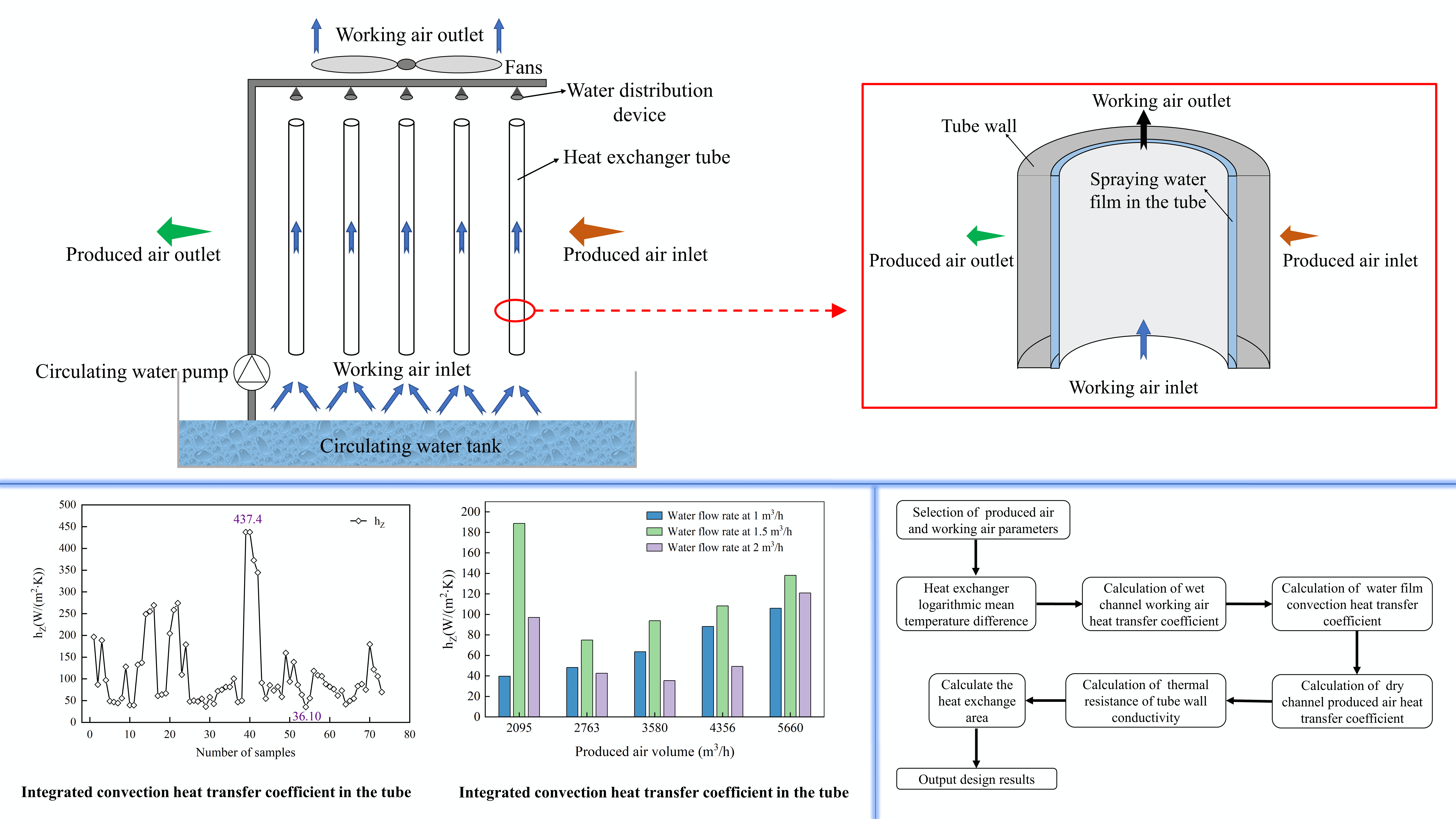
The configuration and heat exchange principle of the VTIEC are illustrated in Figs. 1 and 2, respectively. The core components are the circulating water system, the produced and working air system and the vertically arranged heat exchanger tube with a certain heat exchange performance. The heat exchanger is arranged above the circulating water tank. Under the action of the water pump, the circulating water sprays into the tube through the upper water distribution device, which makes the inner wall of the tube form a uniform attached water film. The water film keeps flowing from top to bottom due to the gravity. At the same time, the working air inlet is arranged below the heat exchanger. Under the negative pressure of the top exhaust fans, the working air flows through the tube of the heat exchanger from bottom to top. The working air and the top-down circulating water film have countercurrent contact and the intense heat and mass transfer occurs here, which cools the circulating water film in the tube. Then, the low temperature water film cools the produced air outside the tube. The cooling limit of the produced air is the wet-bulb temperature of the working air, and the working air is discharged to the outside of VTIEC under the action of exhaust fans [1].
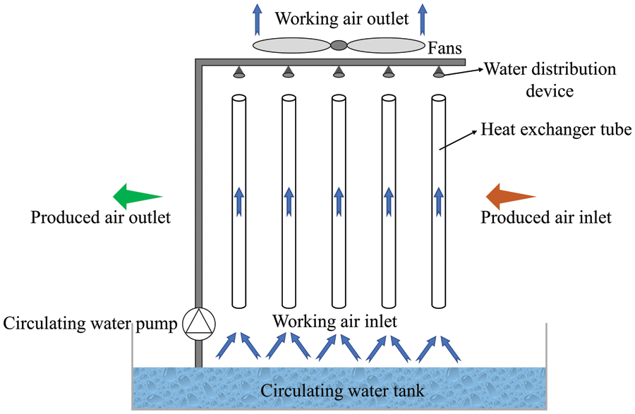
Figure 1: Schematic of the configuration and heat exchange principle of the VTIEC
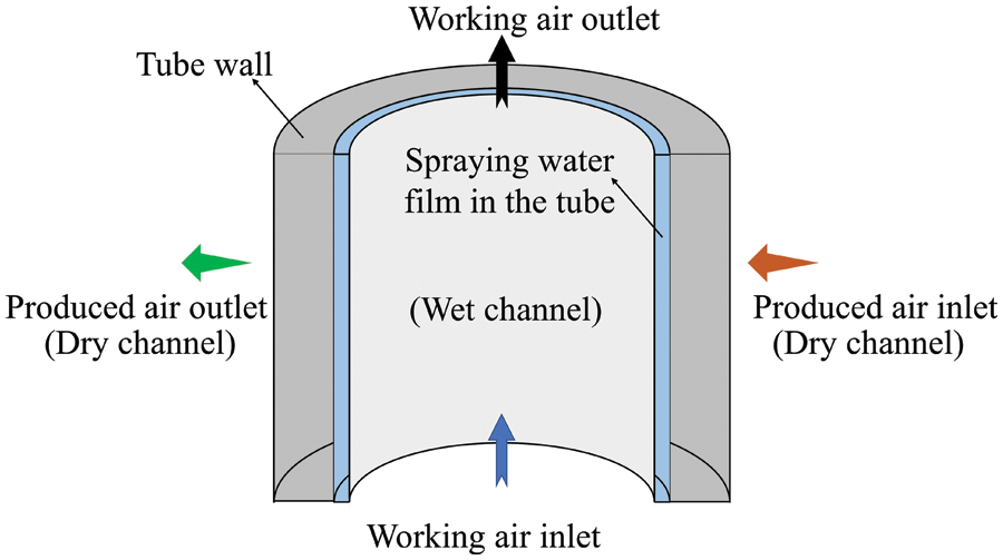
Figure 2: Schematic of the HMTP inside the heat exchanger tubes of the VTIEC
2.2 The Heat and Mass Transfer Model
As mentioned above, the circulating water film flows down the inner wall of the heat exchanger tube of the VTIEC, while the working air will produce counter-flow resistance, which results in forced convection heat transfer. The output air flows outside the heat exchanger tube and conducts indirect heat exchange with the water film inside the tube through the tube wall, which is an equal moisture cooling process [16].
The design calculation process of VTIEC is illustrated in Fig. 3 [17] and is described as follows.
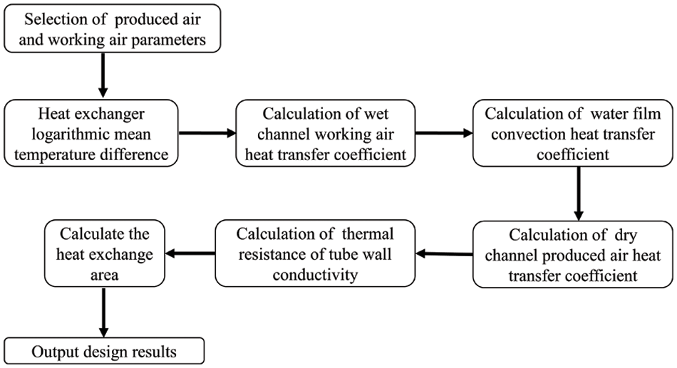
Figure 3: Design flowchart of the VTIEC [17]
Firstly, calculating the logarithmic average temperature difference of heat exchange of the VTIEC. Defining that: the dry-bulb temperature of the air before entering the IEC is tg1, and the wet-bulb temperature is ts1. The working air inside the tube is in direct contact with circulating water film for direct evaporative cooling. The dry-bulb temperature of the produced air outlet is tg2. The dry-bulb temperature of working air outlet is t1, and the wet-bulb temperature is ts2.
Eqs. (1) to (3) are used to calculate the logarithmic average temperature difference of heat transfer [18] according to the inlet and outlet air temperature of the VTIEC, the temperature of circulating water film in the tube.
where tg1 represents the outdoor dry-bulb temperature, °C. t1 represents the dry-bulb temperature of working air outlet, °C. tg2 represents the dry-bulb temperature of the produced air outlet, °C. Δtm represents the heat exchange logarithmic mean temperature difference, °C.
Secondly, as for the calculation of the heat exchange capability of the VTIEC, the volume flow rate of the produced air is V, the average temperature tg = t1 + Δtm. The dry air thermophysical properties, air density ρ, air specific heat capacity at constant pressure cp, thermal conductivity λ, dynamic viscosity μ, kinematic viscosity υ, Prandtl Number constant Pr are queried according to the qualitative temperature (i.e., average temperature).
Based on the temperature drop of the produced air, the heat exchange capability of the VTIEC is calculated as:
where φ represents the heat exchange capability of VTIEC, W. cp represents specific heat capacity of air kJ/(kg⋅K). V represents volume flow rate of produced air, m3/h. ρ represents air density at average temperature, kg/m3.
Then, calculating the heat transfer coefficient h1 between the produced air and the wall in the dry channel. The VTIEC has a rated operating air volume of V m3/h, the heat exchanger tubes are arranged in a staggered row way. The outer diameter of heat exchanger tube is d. A total of x tubes is designed on the windward plane. The transverse and longitudinal distance between the two adjacent tubes are S1 and S2, respectively, as is shown in Fig. 4.
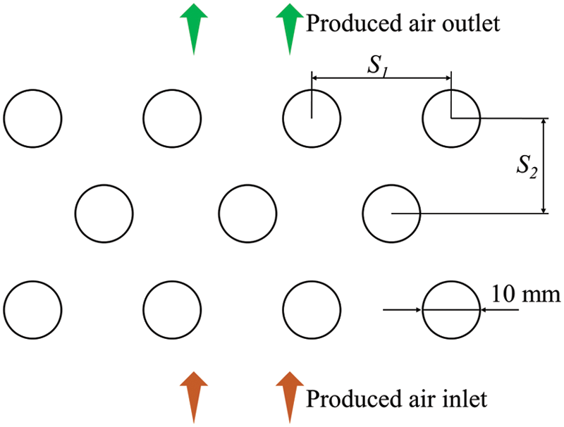
Figure 4: Arrangement for heat exchanger tube
The narrowest circulation area between two adjacent tubes (f) is calculated as:
The total cross-sectional area for fork row (F) is calculated as:
The heat transfer area of tube bundle (A) is calculated as:
where l represents the tube length, m. S1 represents the tube cross-row spacing, m. d represents the tube diameter, m. x represents the number of tubes arranged on the windward plane. n represents the total number of tubes.
Considering the flow around a cylinder, namely, the produced air flows outside the heat exchanger tube in this paper, the maximum flow rate is adopted as the air flow rate, the tube outer diameter d is adopted as the qualitative size, the average air temperature is adopted as the qualitative temperature for the calculation of flow Reynolds number [16], as is shown in Eqs. (8)–(10).
The maximum flow rate is calculated as:
The flow Reynolds number is calculated as:
Based on the reference [8], according to S1/S2 and Eq. (9), the correlation formula of average surface heat transfer coefficient of the tube bundle (h1) is found, and h1 is calculated according to Eq. (10).
where V represents the volume flow rate of produced air, m3/h, where ν represents the kinematic viscosity of air at average temperature, m2/s. λ represents the thermal conductivity of the tube, W/(m⋅°C).
The thermal resistance of tube wall conductivity (R) is calculated as:
Calculate hz in the wet channel according to the heat transfer formula ϕ = KAΔtm. The total heat transfer coefficient K can be calculated according to the flat wall heat transfer method because of the thin wall of the tube [19].
The spray density of the VTIEC (Γ) is calculated as:
where Г represents the water density, kg/(m⋅h). Mw represents the circulating water mass flow rate, kg/h. n represents the number of tubes on the shower surface, Z represents the perimeter of the tube, m.
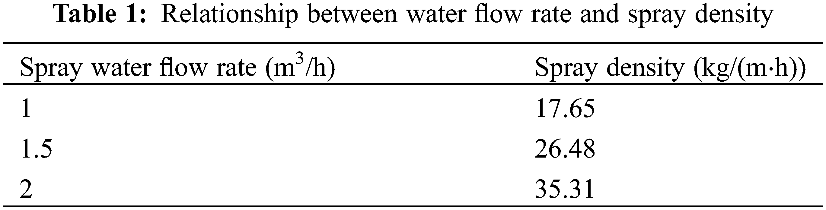
The working air/produced air volume ratio is set as 0.5, 0.6, 0.8 in this paper. The spray water flow rate is set as 1, 1.5, 2 m3/h. and then the spray density of the VTIEC (Γ) is obtained according to Eq. (13). The relationship between spray water flow rate and spray density is shown in Table 1. The spray density is 17.65, 26.48 and 35.31 kg/(m⋅h) when the water flow rate is 1, 1.5 and 2 m3/h.
The wet-bulb efficiency (η) is used to be the performance index of the VTIEC, that is, the ratio of the difference between the dry-bulb temperature of the inlet and outlet of the produced air to the difference between the dry-bulb temperature of the produced air and the wet-bulb temperature of the working air.
where η represents the wet-bulb efficiency. tg1 represents the dry-bulb temperature of produced air inlet, °C. tg2 represents the dry-bulb temperature of the produced air outlet, °C. ts2 represents the wet-bulb temperature of the working air, °C.
As mentioned above, an aluminum VTIEC with a tube diameter of 10 mm is selected and it is composed of 1804 circular tubes arranged in a cross pattern, including 44 odd rows and 45 even rows, with a tube length of 1200 mm, a tube wall thickness of 0.3 mm, S1 of 16 mm and S2 of 16 mm. The produced air flows along the horizontal direction (outside of the tube, dry channel), and the spray water and working air flow along the vertical direction (inside the tube, wet channel). Using the upper water distribution method, and there is a water distribution device above the heat exchanger tube. The water distribution device sprays water into the interior of the tube.
A water baffle is provided at the end of the wet channel to avoid the cooling water from being blown out of the VTIEC. A viewable window is provided in the channel over the top air duct of the device, which makes it easy to observe the internal condition of the duct of the core.
Both the dry channel and the wet channel use press-in fans, and both channels are equipped with 5 mm diameter orifice plates at 0.5 m after the fans, so that the airflow of the incoming air is evenly organized. At the corners of the wet channel and the bottom of the dry channel after the evaporative cooler, removable baffles are set to control the flow direction of the working air. The inlet of the dry and wet channel and the outlet of the dry channel has removable orifice plates with 5 mm apertures for stabilizing the airflow organization.
The spray water used in the VTIEC is recycled and is pumped from the tank by a circulating pump and flows back to the tank after passing through the water distribution device and tubes in the core. The schematic diagram of the VTIEC is illustrated in Fig. 5.
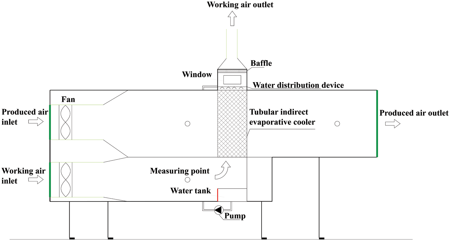
Figure 5: Test rig of the VTIEC
The physical diagram of the experimental setup is illustrated in Fig. 6.

Figure 6: Test rig of VTIDC
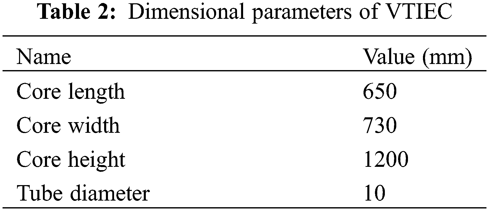
The core of the VTIEC is 650 mm long, 730 mm wide and 1200 mm high, where the tube diameter is 10 mm, Table 2 lists the dimensional parameters of the VTIEC.
In this study, a VTIEC with a tube diameter of 10 mm was used to analyze the effect on the heat transfer coefficient of its tube inner side under different conditions. The experiment data are recorded only when the fans, pumps, and other equipment ran stably. The details of the measuring instruments and parameters are presented in Table 3.
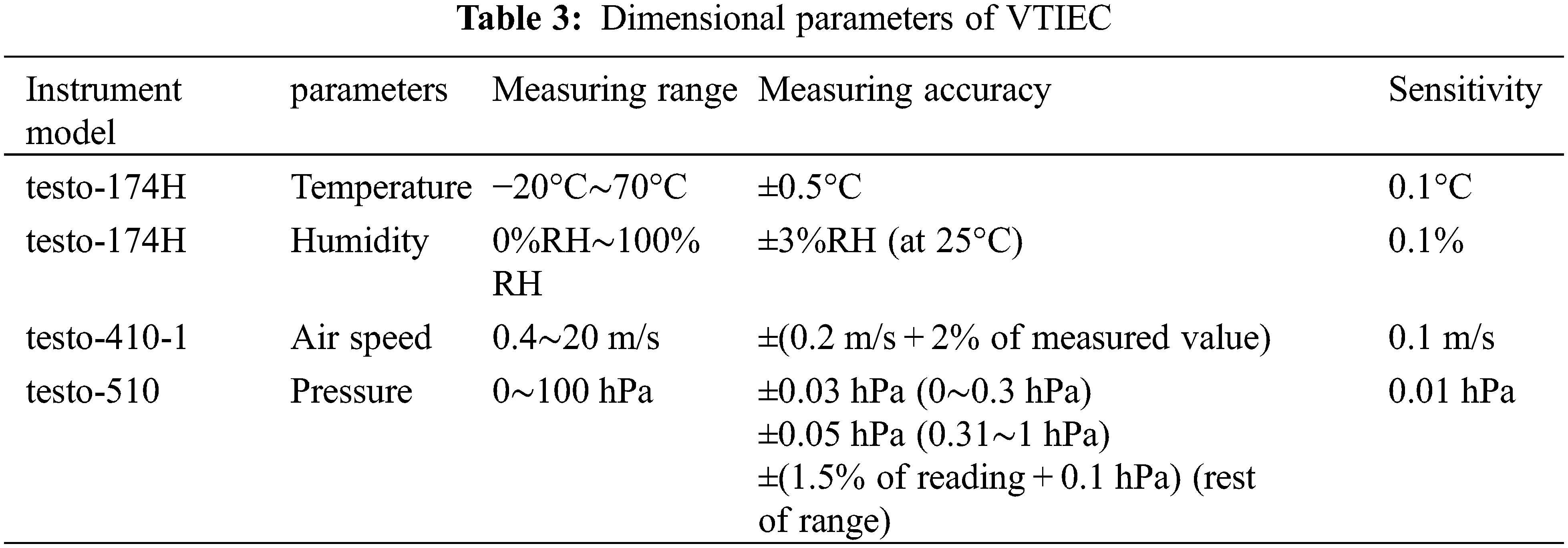
Two instruments were placed at each of the outdoor, produced air outlet and working air outlet for measuring the dry-bulb temperature and relative humidity at the corresponding locations, and the results were averaged from the data of the two instruments. In addition, a handheld anemometer was used to measure the desired air velocity, and the air velocity was read after waiting for the display to stabilize.
Once the operating parameters are changed, the equipment will run for 30 min to ensure that the working condition is stable.
(1) Maximum relative error in temperature
The testo temperature and humidity self-registering instrument has an error of ±0.5°C. The lowest temperature in the actual test was 15.8°C. The maximum value of the relative error was calculated as:
(2) Maximum relative error in humidity
The Testo temperature and humidity self-recording instrument has an error of ±3%RH and the lowest humidity in the actual test was 75.7%. The maximum value of the relative error was calculated as:
(3) Maximum relative error in wind speed
The testo anemometer instrument error is ±0.2 m/s. The lowest wind speed in the actual test was 8.6 m/s. The maximum relative error was calculated as:
The temperature range of the test instrument is −20°C∼70°C, with an accuracy of ±0.5 and a maximum relative error of 3.2%. The humidity range is 0%RH∼100%RH, with an accuracy of ±3%RH and a maximum relative error of 4.0%. The wind speed range is 0.4∼20 m/s, with an accuracy of ±0.2 m/s and a maximum relative error of 2.3%.
4.1 Integrated Convective Heat Transfer Coefficient
In October 2022 in Xi’an, Shaanxi Province, the dry-bulb temperature was 16°C∼18°C (The inlet temperatures of the produced air and the working air are all in this range.), and the difference between dry-bulb temperature and wet-bulb temperature was in the range of 2°C∼4°C, and the test bench of the VTIEC integrated convection heat transfer coefficient was tested. The corresponding calculation results are illustrated in Fig. 7.
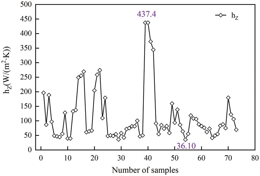
Figure 7: Integrated convection heat transfer coefficient in the tube
By analyzing the experimental results, it can be seen that the outdoor dry-bulb temperature was in the range of 16.35°C∼17.55°C, and the difference between dry-bulb temperature and wet-bulb temperature is about 2°C. The range of the integrated convection heat transfer coefficient of the VTIEC with a diameter of 10 mm is 36.10∼437.4 W/(m2⋅K), which matches the values range studied by scholars in reference [20].
As is shown in Fig. 8, the outdoor dry-bulb temperature ranged from 16°C to 18°C, and the measurements were carried out under different produced air volume and different water flow rates. When the water flow rate was 1.5 m3/h, the integrated convective heat transfer coefficient in the tube was the largest. When the water flow rate was 1.5 m3/h, the spray density was 26.48 kg/(m⋅h). Currently, the wet-side water film thickness is the most appropriate, and its integrated convection heat transfer coefficient is the largest.
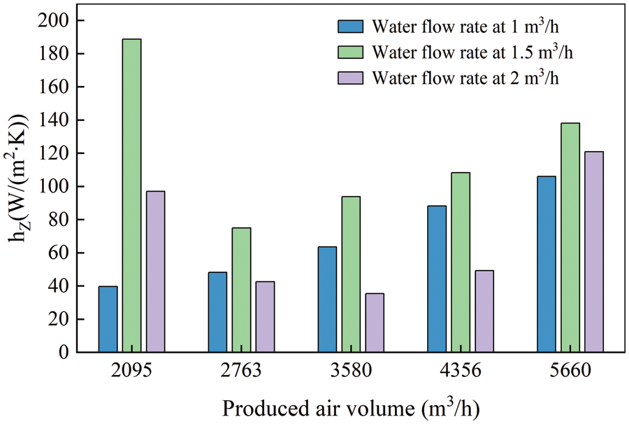
Figure 8: Integrated convection heat transfer coefficient in the tube
The integrated convective heat transfer coefficient under different air velocity is illustrated in Fig. 9. The integrated convective heat transfer coefficient achieved its maximum at the water flow of 1, 1.5, 2 m3/h when the produced air volume was in the range of 2500∼3000 m3/h.
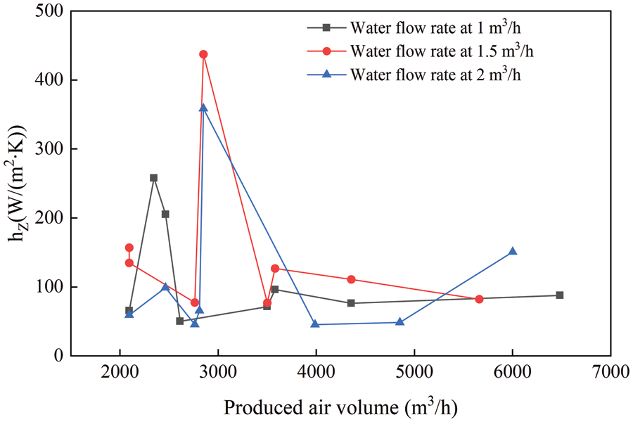
Figure 9: Integrated convection heat transfer coefficient at different water flow rates
4.2 The Relationship between the Spray Density and Wet-Bulb Efficiency
As is shown in Fig. 10, the square pattern represents the working air/produced air volume ratio of 0.5, the circle pattern represents the working air/produced air volume ratio of 0.6, and the triangle pattern represents the working air/produced air volume ratio of 0.8. The integrated convective heat transfer coefficient in the tube is in the range of 36.10∼437.4 W/(m2⋅K). The wet-bulb efficiencies of the three studied working air/produced air volume ratios are the maximum in the case of spray density of 26.48 kg/(m⋅h). The wet-bulb efficiency is generally the highest when the working air/produced air volume ratio is 0.8.
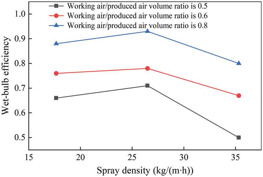
Figure 10: Relationship between the wet-bulb efficiency and spray density at different working air/produced air volume ratios
As is shown in Fig. 11, the wet-bulb efficiency varies monotonically with the ratios of working air volume to produced air volume at the spray density of 17.65, 26.48, and 35.31 kg/(m⋅h), respectively. Under the same working air/produced air volume ratio, the wet-bulb efficiency is the largest when the spray density is 26.48 kg/(m⋅h).
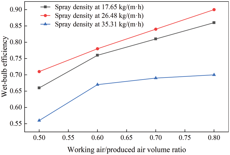
Figure 11: Relationship between working air/produced air volume ratio and wet-bulb efficiency at varying spray density
During the design process of the VTIEC, there are two most important parameters (i.e., the surface heat transfer coefficient between the produced air and the aluminum tube h1 and the working air integrated convection heat transfer coefficient hZ) that affect its design accuracy. The h1 has been studied by many scholars but the working air integrated convection heat transfer coefficient hZ is measured as the water medium inside the tube of the 200∼12000 W/(m2⋅K) range.
Evaporative cooling equipment tube is not completely filled with the water medium but a two-phase flow (i.e., water and air). Therefore, the value of the integrated convective heat transfer coefficient in the two-phase flow state differs from the heat transfer coefficient when the water medium is passed through the tube. To solve this problem, this paper used a 10 mm tube diameter indirect evaporative cooler to carry out experimental measurement of the actual working conditions. When the outdoor dry-bulb temperature is in the range of 16°C∼18°C, the value of the integrated convection heat transfer coefficient of the water side of the tube under this condition is in the range of 36.10∼437.4 W/(m2⋅K).
Through the calculation of the integrated convection heat transfer coefficient in the tube, the factors affecting this coefficient were analyzed, and the integrated convection heat transfer coefficient in the tube was the largest when the water flow rate was 1.5 m3/h.
In this test, the measured integrated convection heat transfer coefficient in the tube ranged from 36.10 to 437.4 W/(m2⋅K), and the wet-bulb efficiencies of the three working air/produced air volume ratios were all at a maximum when the spray density was 26.48 kg/(m⋅h), and the VTIEC reached the highest efficiency. Generally, the wet-bulb efficiency is the highest when the working air/produced air volume ratio is 0.8.
The wet-bulb efficiency increases with the increase in the working air/produced air volume ratio when the integrated convective heat transfer coefficient in the tube is within the range of 36.10∼437.4 W/(m2⋅K). At the same working air/produced air volume ratio, the wet-bulb efficiency is the largest when the spray density is 26.48 kg/(m⋅h).
Funding Statement: This work was supported by Natural Science Basic Research Program of Shaanxi (2021JQ-689).
Conflicts of Interest: The authors declare that they have no conflicts of interest to report regarding the present study.
References
1. Huang, X. (2010). Theory and application of evaporative cooling air conditioning. Beijing, China: China Construction Industry Press. [Google Scholar]
2. Zhou, X. Q., Chen, P. L. (2000). Design calculation method of indirect evaporative cooler. HVAC, (1), 39–42. [Google Scholar]
3. Zhang, X., Chen, J. H., Chen, P. L. (1998). Analytical solution and verification of the transfer process of a tubular indirect evaporative cooler. Journal of Tongji University, (4), 461–465. [Google Scholar]
4. Yu, J. L., Jin, L. W., Cao, Q., Wang, Y. Y., Wu, Y. Z. (1999). Experimental study of horizontal single-tube external convection mass transfer in a tubular indirect evaporative cooler. Journal of Xi’an Jiaotong University, 33(3), 67–71. [Google Scholar]
5. Abdalazeem, A., Han, D., He, W. F., Majid, A., Zhong, H. (2022). Numerical investigation of the heat and mass transfer process within a cross-flow indirect evaporative cooling system for hot and humid climates. Journal of Building Engineering, 45, 103499. https://doi.org/10.1016/j.jobe.2021.103499 [Google Scholar] [CrossRef]
6. Riangvilaikul, B., Kumar, S. (2010). Numerical study of a novel dew point evaporative cooling system. Energy & Buildings, 42(11), 2241–2250. https://doi.org/10.1016/j.enbuild.2010.07.020 [Google Scholar] [CrossRef]
7. Riangvilaikul, B., Kumar, S. (2010). An experimental study of a novel dew point evaporative cooling system. Energy & Buildings, 42(5), 637–644. https://doi.org/10.1016/j.enbuild.2009.10.034 [Google Scholar] [CrossRef]
8. Pandelidis, D., Anisimov, S. (2015). Numerical analysis of the heat and mass transfer processes in selected M-cycle heat exchangers for the dew point evaporative cooling. Energy Conversion and Management, 90, 62–83. https://doi.org/10.1016/j.enconman.2014.11.008 [Google Scholar] [CrossRef]
9. Pandelidis, D., Anisimov, S. (2016). Numerical study and optimization of the cross-flow maisotsenko cycle indirect evaporative air cooler. International Journal of Heat and Mass Transfer, 103, 1029–1041. https://doi.org/10.1016/j.ijheatmasstransfer.2016.08.014 [Google Scholar] [CrossRef]
10. Doroshenko, A. V., Kirillov, V. H., Ludnitsky, K. V., Goncharenco, V. A. (2015). Direct evaporatrive coolers of gases and liquids with lowered limit of cooling. Problems of the Regional Energetics, 3(29), 74–85. [Google Scholar]
11. Bolotin, S., Vager, B., Vasilijev, V. (2015). Comparative analysis of the cross-flow indirect evaporative air coolers. International Journal of Heat and Mass Transfer, 88, 224–235. https://doi.org/10.1016/j.ijheatmasstransfer.2015.04.072 [Google Scholar] [CrossRef]
12. Anisimov, S., Pandelidis, D. (2015). Theoretical study of the basic cycles for indirect evaporative air cooling. International Journal of Heat and Mass Transfer, 84, 974–989. https://doi.org/10.1016/j.ijheatmasstransfer.2015.01.087 [Google Scholar] [CrossRef]
13. Anisimov, S., Pandelidis, D., Danielewicz, J. (2015). Numerical study and optimization of the combined indirect evaporative air cooler for air-conditioning systems. Energy, 80, 452–464. https://doi.org/10.1016/j.energy.2014.11.086 [Google Scholar] [CrossRef]
14. Vahabi, M. K., Hamidreza, A., Sareh, D., Rahim, Z. (2022). Thermal analysis and optimization of indirect flat evaporative coolers. International Journal of Thermofluids, 16, 100246. https://doi.org/10.1016/j.ijft.2022.100246 [Google Scholar] [CrossRef]
15. Asemi, H., Zahedi, R., Daneshgar, S. (2023). Theoretical analysis of the performance and optimization of indirect flat evaporative coolers. Future Energy Open Access, Journal, 2(1), 9–14. [Google Scholar]
16. Zhang, X. M. (2007). Heat transfer, 5th Edition. China: China Industry Press. [Google Scholar]
17. Chang, J. P., Huang, X., Jia, C. Y., Du, D. Y., Xu, J. J. (2020). Design and applicability study of riser-type indirect evaporative cooler. Fluid Mechanics, 48(12), 68–73. [Google Scholar]
18. Fan, L. J., Huang, X., Xu, F. C. (2011). Performance testing and analysis of tubular indirect evaporative chillers. Building Science, 27(10), 55–57. [Google Scholar]
19. Wang, F., Wu, J. M., Huang, X., Wang, Z. J. (2009). Establishment and validation of heat and mass transfer model for tubular indirect evaporative cooler. The First China (Xi’an) Symposium on Energy Saving and Emission Reduction Technology for Heating, Ventilation, Refrigeration and Air Conditioning, pp. 75–87. Xi’an, China. [Google Scholar]
20. Song, X. L. (2014). Experimental study of standpipe indirect-target nozzle composite evaporative cooling air conditioning unit (Master Thesis). Xi’an University of Engineering, China. [Google Scholar]
Cite This Article
 Copyright © 2023 The Author(s). Published by Tech Science Press.
This work is licensed under a Creative Commons Attribution 4.0 International License , which permits unrestricted use, distribution, and reproduction in any medium, provided the original work is properly cited.
 Downloads
 Citation Tools