
 Submit a Paper
 Propose a Special lssue
 Open Access
ARTICLE

Numerical Analysis of Cavity-Based Control of Base Pressure Variations at Supersonic Mach Numbers
1
Mechanical and Aerospace Engineering Department, Faculty of Engineering, International Islamic University, Kuala Lumpur,
53100, Malaysia
2
Department of Engineering Management, College of Engineering, Prince Sultan University, Riyadh, 11586, Saudi Arabia
* Corresponding Author: Sher Afghan Khan. Email:
Fluid Dynamics & Materials Processing 2023, 19(6), 1655-1678. https://doi.org/10.32604/fdmp.2023.025230
Received 30 June 2022; Accepted 27 September 2022; Issue published 30 January 2023
 View Full Text
 Download PDF
Abstract
In the present study, the base pressure variations induced by the presence of a cavity, known to have a strong influence of the behaviour of supersonic projectiles, are investigated through numerical solution of the balance equations for mass, momentum, and energy. An area ratio of four is considered and numerical simulations are carried out at Mach M = 1.2, 1.4, 1.6, and 1.8 assuming no cavity or cavity locations 0.5D, 1D, 1.5D, and 2D. The inlet pressure of the nozzle is considered as a flow variable. The Taguchi method is also used, and the considered cases are then analyzed using a full factorial experimental design. The results show that the cavity is effective in increasing the base pressure for the conditions examined. For other nozzle pressure ratios, cavities do not lead to passive control due the change in the reattachment length. The distribution of wall pressure reveals that, in general, a cavity used to implement passive control of the base pressure does not adversely influence the flow pattern in the domain.Keywords
Nomenclature
| D | Enlarged duct diameter |
| M | Mach number |
| C | Location of the cavity from the nozzle exit |
| CD | Convergent-Divergent |
| CFD | Computational fluid dynamics |
| NPR | Nozzle pressure ratio |
| L | Length of duct |
| Pb | Base pressure |
| De | Nozzle exit diameter |
| Di | Nozzle inlet diameter |
| Dt | Nozzle throat diameter |
| Lc | Nozzle converging length |
| Ld | Nozzle diverging length |
| ASR1 | Models with cavity aspect ratio 1 (3:3) |
| ASR2 | Models with cavity aspect ratio 2 (6:3) |
| ST | Duct without cavity |
| WC | Duct without cavity |
| 0.5D | Cavity location at 10 mm in the duct |
| 1D | Cavity location at 20 mm in the duct |
| 1.5D | Cavity location at 30 mm in the duct |
| 2D | Cavity location at 40 mm in the duct |
| u | Instantaneous velocity |
| V | Velocity modulus |
| ρ | Gas density |
| P | Gas pressure |
| qj | Heat flux |
| τij | Viscous stress tensor |
The study of base pressure in a high-speed supersonic flow is an important topic, as the resulting base drag contributes to nearly seventy per cent of the total drag of missiles, rockets, and projectiles. However, even a slight rise in pressure will significantly reduce the base drag and this decrease in the base drag will cause a significant improvement in the overall performance of the projectiles. Hence, many researchers are currently working on ways to control base pressure. A search of the literature reveals that there are two ways to regulate base pressure. One is a dynamic/active control, and the other is passive control. Passive control of the base pressure can be achieved through changes to the geometry of the flow field. Whereas, for dynamic/active control, an additional source of energy is needed to achieve control. In dynamic conditions, arranging external energy sources may not always be feasible.
Pandey et al. [1] have studied base pressure control using a cavity in a sudden expansion duct of the CD nozzle and show that the use of cavities will result in reducing the recirculation zone of the base region. Pathan et al. [2] have numerically simulated the base pressure in external and internal flows and found that the variations in base pressure are similar in external and internal flows. Similarly, a number of studies have been found in reducing the drag and increasing the base pressure using dynamics/active [3–8] and passive methods [9–14], considering the convergent-divergent (CD) nozzle inlet flow. Recently a numerical study has been carried out in a multi-jet with a divergent upstream ramp at supersonic cross flow. The findings show that a strong vortex produced in low jet space is more effective on fuel mixing than low multi vortices [15]. Also, by solving a half-plane problem with the symmetric line treated as the reflecting surface, symmetric Mach reflection in steady supersonic flow was examined, but the chance to identify antisymmetric flow structures was lost [16].
On the other hand, control of supersonic compression corner flow using a plasma actuator has been recognized as a practical approach [17]. Several studies, as described hereafter, have shown the benefits of the practical method of using the plasma actuators in supersonic flow and determining the pressure and flow rates when controlled and uncontrolled [18–23]. In some studies, the simulation of a CD rocket nozzle using computational fluid dynamics (CFD) was analyzed [24] and showed the performance of flows in a nozzle. Numerical analysis of the gas flow dynamics from a rectangular slot-nozzle for pulse cleaning of a filter unit was studied [25] and proved the effectiveness of the rectangular slot. In some cases, the nozzle has been changed in different forms like De-Laval nozzle designs employed for surface plasma figuring were investigated [26] with the flow formations. The theoretical & experimental data of the CD nozzle were analyzed and compared [27] and theoretical data was validated with the experimentation. Using the CFD approach it has been also determined the flow over the CD nozzle called external flows as well as internal flows were also determined for axisymmetric convergent-divergent nozzles on an over-expansion state [28] and the study found it very appealing in the fluid flow analysis. Also, the con-di type of nozzle was found with a simulation approach in which the study of large eddy supersonic jet plumes from rectangular con-di nozzles was done [29]. A three-dimensional CD nozzle was used to investigate the shock train structure [30] and flow analysis using CFD was studied [31]. Using different non-equilibrium condensation models, a numerical solution of stream flow in a nozzle was investigate [32], and a homogeneous equilibrium model and cavitation pattern in CD nozzles of diesel injectors in the nozzle flow was studied [33]. In CD nozzle, comparative analysis of K-epsilon and Spalart-Allmaras turbulence models for compressible flow is studied and found effective in fluid properties analysis.
Additionally, the flow of control outside the system/object has been determined very well using the CFD approach, from which results show adequate information and significant appropriateness for the fluid flow analysis. In recent years, ANSYS fluent study was found for the sharp wedge flow formation, and shock observations were determined with the CFD approach and compared with the theoretical results [34,35]. Similarly, to control the flow in the bluff body, a non-circular cylinder was utilized and determined the flow rate [36,37], and a splitter plate was used to reduce the drag [38,39]. Also, a study showed the simulations over a airfoil for determining the flow rates using the CFD method [40,41]. Based on all the above literature and studies, we can conclude that the CFD method helps to assess flow rates.
The objective of the current work is focused on passive control using a cavity in a CD expansion duct of the nozzle. The waves dominate supersonic flows, and the combination of each parameter will give different outcomes and variations in flow and geometrical parameters provide a different flow pattern was determined. The cavity in the duct is employed to determine its effectiveness on the base pressure control. While simulating the flow, the nozzle inlet pressure has been considered as a flow variable. The duct diameter considered for the analysis is 20 mm, and the cavity used for the flow control has dimensions 3:3. Therefore, the current work with the finite volume method designed and modelled the three-dimensional CD nozzle with a circular duct and the duct controlled by the cavities to reduce the base drag and determine the pressure rates. Additionally, a Taguchi method was used to optimize the flow parameters and nozzle dimensions for the optimum solution of base drag control and increase the flow rate of the duct.
Fig. 1 shows the CD nozzle connected with an enlarged duct. When the fluid passes through the diverging nozzle and is exhausted in a pipe with a larger area, low pressure is formed in the base region. This negative pressure results in base drag. The passive and active methods are utilized to regulate the base flows.
Figure 1: The CD nozzle and enlarged duct with annular cavity
The parameters considered for the current work are Mach number (M), length-to-diameter ratio (L), Cavity location (C), and Nozzle pressure ratio (NPR). The enlarged duct diameter (D) is constant at 20 mm and the exit diameter of the nozzle is 10 mm. The nozzle dimensions are calculated for various Mach numbers and presented in Table 1. The geometries are modelled in the ANSYS workbench for all the combinations of the parameters and analyzed in Fluent software.
Since the duct is axisymmetric, this results in a reduction of the computation time. Using 2D or 3D analysis with the half model, numerical simulations can be done easily by considering the symmetric model. We may consider symmetric about one plane and 3D analysis with the quarter model, i.e., symmetric about two planes. Fig. 2 shows the complete 3D model and boundary conditions, and Fig. 3 shows the quarter 3D model and boundary conditions. The quarter 3D model is selected for further analysis to get better results in optimal time.
Figure 2: Complete 3D model for CFD analysis and boundary condition
Figure 3: Quarter 3D model for CFD analysis and boundary condition
2.2 Meshing and Boundary Conditions
Fig. 3 illustrates the three-dimensional finite volume model with appropriate boundary conditions. The pressure inlet is considered the entry, and the pressure outlet is considered the duct exit. The pressure to be specified at the inlet is calculated as per the nozzle pressure ratio (NPR) and assigned. The pressure at the duct exit plane is regarded as zero-gauge pressure. Fig. 4 shows the 3D meshed model for CFD analysis. The 3D model uses an ANSYS workbench to mesh with a hexahedral mesh element. To develop hexahedral elements, the complete model is divided into a number of sub volumes, and each sub volume has meshed separately.
Figure 4: 3D meshed model
2.3 CFD Analysis and Post-Processing
The CFD analysis is done using ANSYS fluent for all the groupings of constraints by considering a complete factorial design. The K-epsilon turbulent model is utilized during computation, giving more accurate results in a reasonable time [2–8]. Hence the k-epsilon method is used for the analysis. As it is a compressible flow, a density-based solver is used. As an ideal gas, the air is considered the study’s working medium. The equations considered for a fluid flow analysis are the continuity equation (Eq. (1)), momentum equation (Eq. (2)), and energy equation (Eq. (3)), which are written below:
The results for the base pressure are extracted from the fluent software. The pressure values are gauge pressure, converted into absolute pressure, and then normalized by ambient pressure. The purpose of converting the base pressure into dimensionless base pressure is to better visualize and understand the results. The pressure contours are also extracted from the fluent software.
The grid element size plays a significant role in numerical analysis. The element sizing should be optimized to get accurate results in minimal computation time. To optimize the grid size, the grid independence test is carried out for grid element sizes of 0.1 to 5 mm. Table 2 shows the grid independence test results for various grid element sizes and dimensions. Based on the current results it has been found that the base pressure has sudden enhancement when it reaches greater than one and increment after one has far variation in results. However, when the element size 0.1 to 1.0 mm a large difference was found at 3.35 × 10⁻³ which is small, but the base pressure was found very less when it is 0.5 or 1.0 mm. Indeed, the use of 0.5 or 1.0 mm has approximately the same results we choose 0.5 mm because of less computational time and the grid element size of 0.5 mm is used for further CFD analysis of the current work.
2.5 Validation of CFD Analysis Results
In order to validate or confirm the CFD model the benchmark work of Pandey et al. [1] was selected to compare the base pressure results and the results were found good agreement with the present work. All three models designed without a cavity, cavity with an aspect ratio equal to 1, and cavity with an aspect ratio equal to 2, are determined using CFD analysis. Fig. 5 shows the CFD and experimental results for various length-to-diameter ratios.
Figure 5: Validation of CFD results with experimental results [1]
The per cent variation in CFD analysis results and the experimental outcomes are shown in Table 3. It can be seen that in most of the cases, the variation is less than 5%.
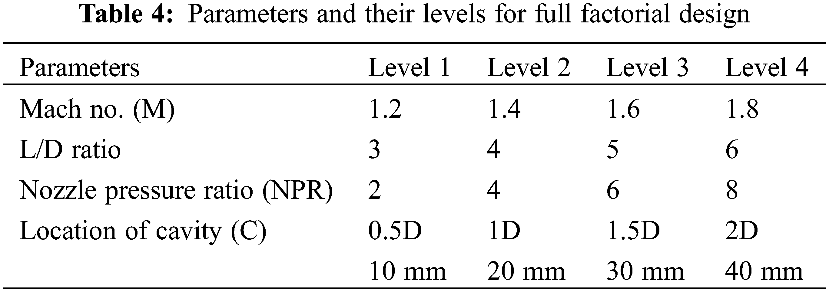
The Taguchi approach optimizes the design parameters to minimize variation before optimizing the design to achieve the target value of the output parameters. The Taguchi approach employs special orthogonal arrays to investigate all design factors with minimal investigation [42]. The complete factorial design is considered for the CFD analysis in the latter part of the research. For a complete factorial design, the (AR) area ratio is fixed at 4. The tube diameter for area ratio 4 is 20 mm, and the nozzle exit diameter is 10 mm. The aspect ratio, i.e., the width to height ratio of the cavity, considered for the CFD analysis is 1 (3:3). The variables studied for the investigation are the Mach number (M), L/D ratio, NPR, and Cavity location (C) concerning duct diameter (D). Table 4 presents the constraints and their levels. The CFD assessment is carried out for all good groupings of these constraints by considering cavity and without cavity. The total number of trials with cavities and without cavities is 320.
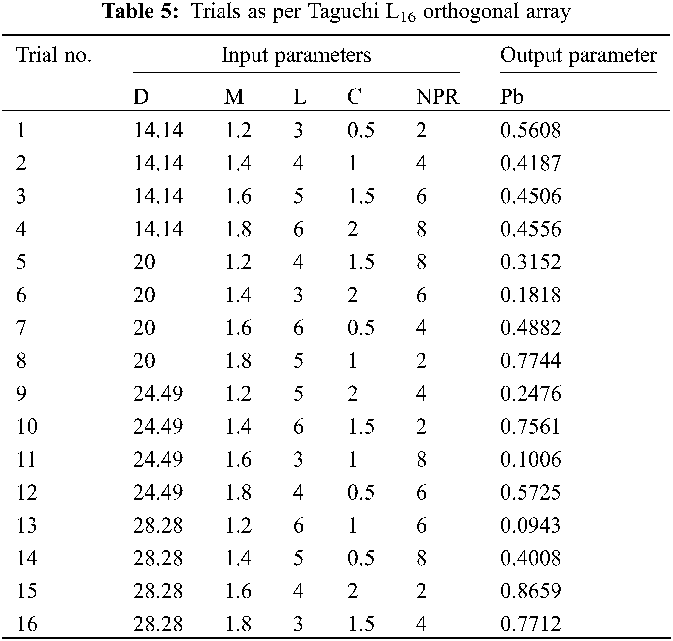
The Taguchi orthogonal array L16 is used in the CFD analysis’ initial stage to identify the various parameters’ main and interaction effects. The input parameters used in Taguchi orthogonal array are duct diameter (D) with sudden expansion, Mach number (M), length-to-diameter-ratio (L), cavity location (C), and nozzle pressure ratio (NPR). The base pressure (Pb) is considered an output parameter. Table 5 presents the L16 orthogonal array.
3.1 Taguchi Method: Main Effect Plots
Fig. 6 shows the plot of the main effects of various parameters on base pressure. It is seen that the parameters, diameter of duct (D), Mach number (M), length to diameter ratio (L), cavity location (C), and nozzle pressure ratio (NPR), have a significant effect on base pressure. The parameter that most influences base pressure is expansion level (NPR). The pressure in the base area reduces significantly due to an increase in the nozzle pressure ratio.
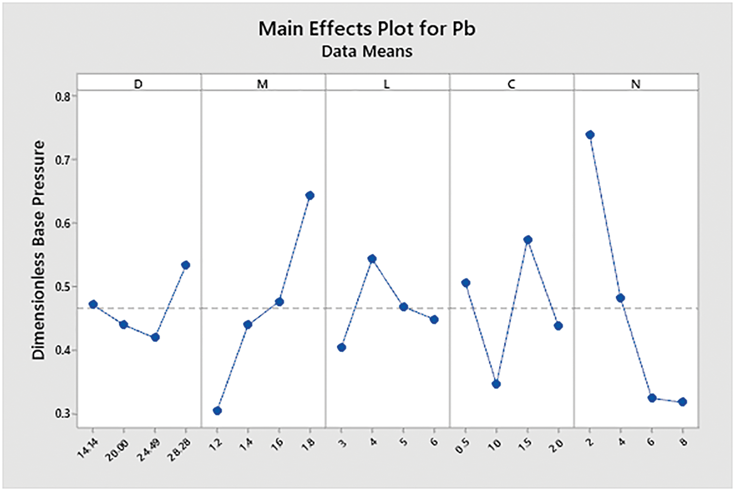
Figure 6: Main effect of parameters
Fluent software extracts provide the total pressure contours to aid in understanding the pressure variations in the CD nozzle and enlarged duct. The pressure contours for L/D = 6, Mach 1.2–1.8, and NPR’s 2–8 are extracted. Figs. 7 to 26 show the total pressure contours for these various cases. The reattachment length is the point from the nozzle exit at which the flow is reattached to the duct.
Figure 7: Pressure contours: L/D = 6 Mach no. = 1.4, NPR = 2 and without cavity

Figure 8: Pressure contours: L/D = 6 Mach no. = 1.4, NPR = 2 and cavity at 0.5D
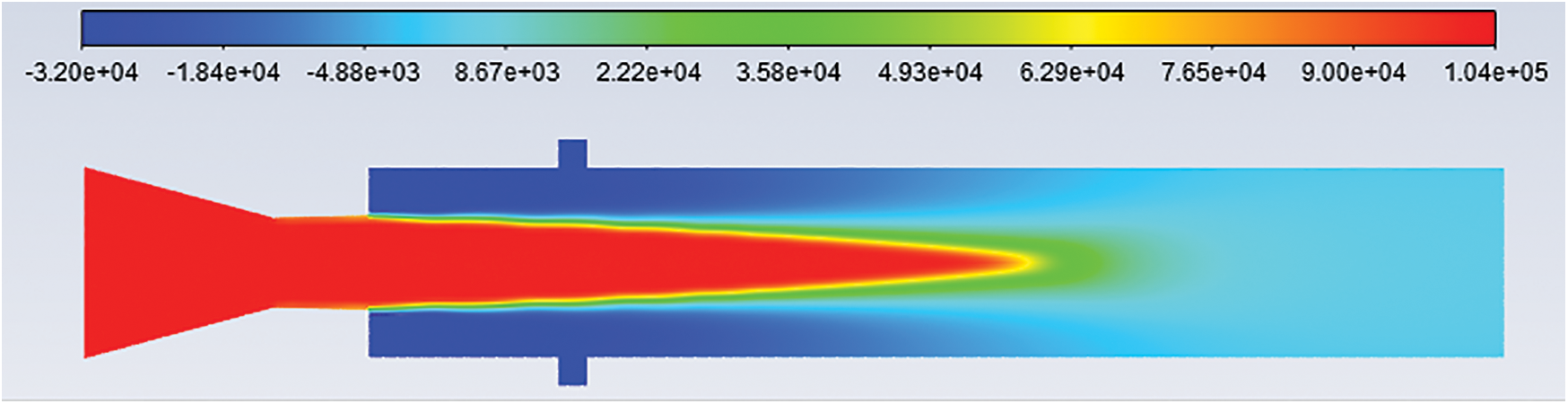
Figure 9: Pressure contours: L/D = 6 Mach no. = 1.4, NPR = 2 and cavity at 1D
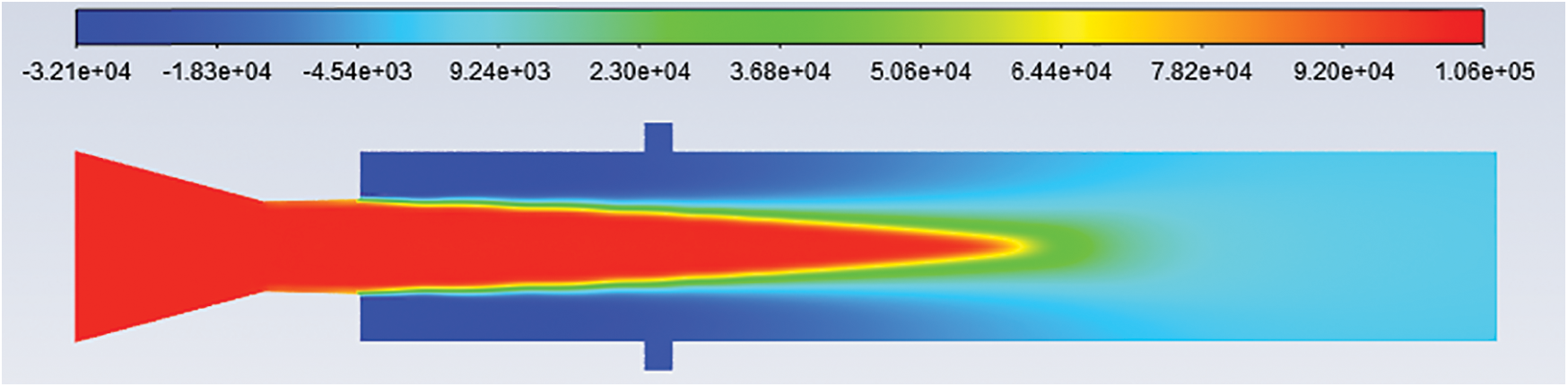
Figure 10: Pressure contours: L/D = 6 Mach no. = 1.4, NPR = 2 and cavity at 1.5D
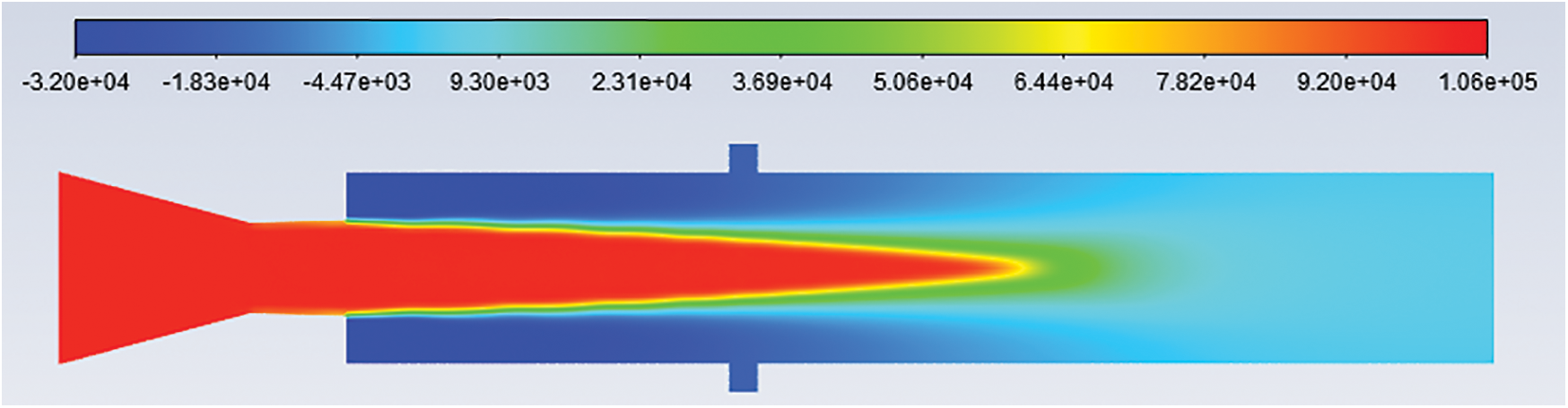
Figure 11: Pressure contours: L/D = 6 Mach no. = 1.4, NPR = 2 and cavity at 2D
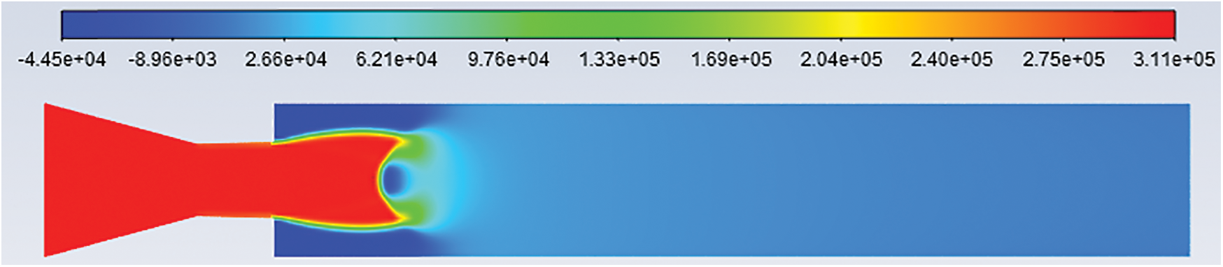
Figure 12: Pressure contours: L/D = 6 Mach no. = 1.4, NPR = 4 and without cavity
Figure 13: Pressure contours: L/D = 6 Mach no. = 1.4, NPR = 4 and cavity at 0.5D
Figure 14: Pressure contours: L/D = 6 Mach no. = 1.4, NPR = 4 and cavity at 1D
Figure 15: Pressure contours: L/D = 6 Mach no. = 1.4, NPR = 4 and cavity at 1.5D
Figure 16: Pressure contours: L/D = 6 Mach no. = 1.4, NPR = 4, and cavity at 2D

Figure 17: Pressure contours: L/D = 6 Mach no. = 1.4, NPR = 6 and without cavity
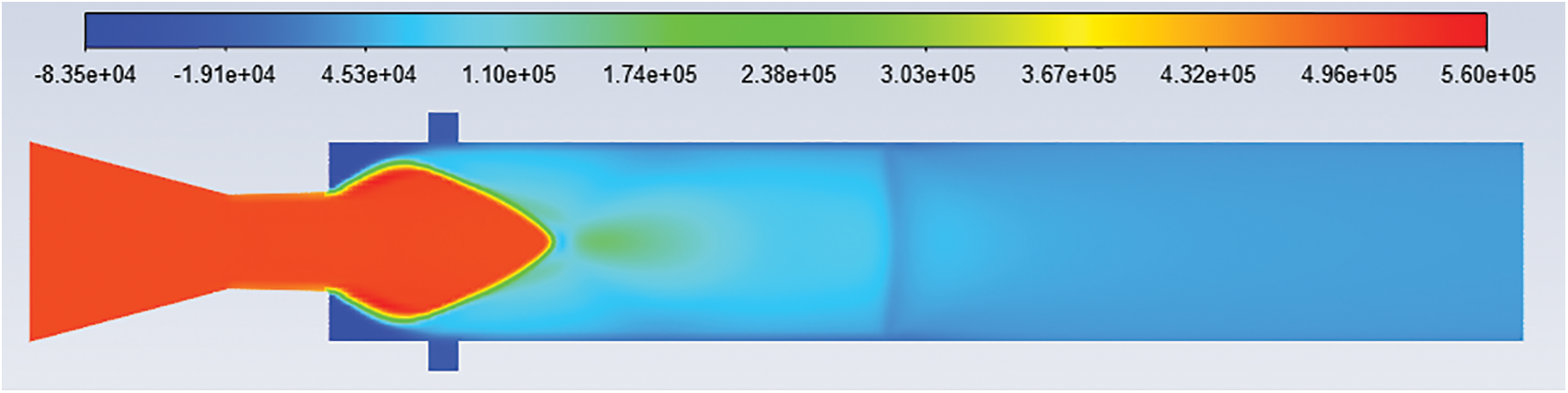
Figure 18: Pressure contours: L/D = 6 Mach no. = 1.4, NPR = 6 and cavity at 0.5D

Figure 19: Pressure contours: L/D = 6 Mach no. = 1.4, NPR = 6 and cavity at 1D
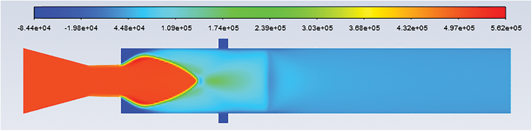
Figure 20: Pressure contours: L/D = 6 Mach no. = 1.4, NPR = 6 and cavity at 1.5D

Figure 21: Pressure contours: L/D = 6 Mach no. = 1.4, NPR = 6 and cavity at 2D
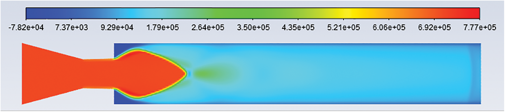
Figure 22: Pressure contours: L/D = 6 Mach no. = 1.4, NPR = 8 and without cavity
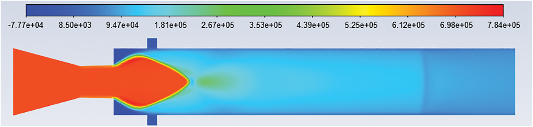
Figure 23: Pressure contours: L/D = 6 Mach no. = 1.4, NPR = 8 and cavity at 0.5D

Figure 24: Pressure contours: L/D = 6 Mach no. = 1.4, NPR = 8 and cavity at 1D
Figure 25: Pressure contours: L/D = 6 Mach no. = 1.4, NPR = 8 and cavity at 1.5D

Figure 26: Pressure contours: L/D = 6 Mach no. = 1.4, NPR = 8 and cavity at 2D
4.1 Pressure Contours: L/D = 6, Mach No. = 1.4, NPR = 2
Figs. 7–11 show the pressure contours for L/D 6, Mach number 1.4, nozzle pressure ratio 2 for without cavity and with a cavity at 0.5D, 1D, 1.5D, and 2D locations. It can be seen that the flow from the CD nozzle is over-expanded. At Mach M = 1.4, the nozzle pressure ratio needed for correct expansion is 3.18 [21]. Hence the expansion level for nozzle pressure ratio 2 is 0.6289.
4.2 Pressure Contours: L/D = 6, Mach No. = 1.4, NPR = 4
Figs. 12–16 show the pressure contours of L/D 6, Mach number 1.4, nozzle pressure ratio 4 for without cavity and with a cavity at 0.5D, 1D, 1.5D, and 2D locations. From Figs. 12–16, it is found that the jet is under-expanded. For Mach 1.4, the nozzle pressure ratio needed for correct expansion is 3.18 [21]. Hence expansion level for nozzle pressure ratio 4 is 1.2578.
4.3 Pressure Contours: L/D = 6, Mach No. = 1.4, NPR = 6
Fig. 17–21 show the pressure contour for L/D 6, Mach number 1.4, and nozzle pressure ratio 6 without cavity and with a cavity at 0.5D, 1D, 1.5D, and 2D locations. It is observed that the jet is under-expanded. The level of expansion for nozzle pressure ratio 6 is 1.8869.
4.4 Pressure Contours: L/D = 6, Mach No. = 1.4, NPR = 8
Figs. 22–26 show the pressure contours for L/D 6, Mach number 1.4, and nozzle pressure ratio eight without cavity and with a cavity at 0.5D, 1D, 1.5D, and 2D locations. The nozzle is highly under-expanded, as seen in Figs. 22–26. The level of expansion for NPR = 8 is 2.5157.
4.5 CFD Analysis Results: Base Pressure for Mach No. 1.2
Before analyzing the base pressure results due to the cavities, it is necessary to explain the physics of the flow when the shear layer is exhausted in a duct with a larger area. When the Mach number is less than unity, the boundary layer will get separated, expanded, and reattached to the enlarged duct after exiting from the nozzle. The separated region will contain one or more vortices as the first vortex will be close to the base and relatively strong. This vortex is named the central vortex. It works like a pump and transfers fluids from the base region to the main jet, which is on the side of the edge of the boundary layer. Due to this pushing activity, low pressure will be created in the recirculation zone. However, as is known, this vortex spread is a periodic phenomenon, making pushing activity too irregular. This irregular pattern causes fluctuations in the base pressure. However, while conducting the tests, it is observed that these variations in the base pressure are negligible. Hence, we take the mean base pressure values while analyzing the results. Owing to the cyclicity of the vortex desquamation, the complete flow pattern in the enlarged duct may turn out to be oscillatory. These oscillations may become very severe for a set of geometrical and inertia parameters. The intensity of the central vortex positioned at the base mainly depends on the level of expansion, reattachment length, the Mach number, and the area ratio.
We theorize that in the flow-through of the CD nozzle, the exiting jet may result from either of three conditions, i.e., the flow may be ideally expanded, under-expanded, or over-expanded. In the case of ideal expansion, the exiting shear layer dominated by waves across the stream flow will be isentropic. A strong shock wave will be located where the nozzle experiences adverse pressure at the nozzle exit. This shock will make the flow move to the main flow, resulting in a delay of reattachment and more significant reattachment length, which will significantly influence the strength of the primary vortex and hence the base pressure values. Finally, for under-expanded nozzles, an expansion fan accelerates the flow as the flow is expanded, and flow will turn away towards the base, resulting in early reattachment and smaller reattachment length. When cavities exist in the duct, these grooves in the form of a cavity will generate additional vortices. These other vortices will act as promoters of mixing despite being small in size thereby, resulting in higher base pressure.
Figs. 27 to 30 show the variations of base pressure. The parameters considered are nozzle pressure ratio, with and without a cavity, and various cavity locations for Mach number 1.2. It can be seen that the cavity is effective only at NPR = 4. At NPR = 4, the cavity is effective at all locations, i.e., 0.5D, 1D, 1.5D, and 2D, but at 1D, the cavity is most effective in increasing the base pressure. At NPR’s 2, 6, and 8, the change in base pressure using cavity is negligible for L/D ratios 3, 4, and 6. At NPR’s 2 and 4, the variation in the base pressure using cavity is small but considerable for L/D ratio 5.
Figure 27: Base pressure vs. NPR, Mach M = 1.2 & L/D = 3

Figure 28: Base pressure vs. NPR, Mach M = 1.2 & L/D = 4

Figure 29: Base pressure vs. NPR, Mach M = 1.2 & L/D = 5
Figure 30: Base pressure vs. NPR, Mach M = 1.2 & L/D = 6
4.6 CFD Analysis Results: Base Pressure for Mach No. 1.4
Figs. 31 to 34 show the variations of base pressure. The constraints studied are NPR, without a cavity, and various cavity locations for Mach number 1.4. Figs. 31 to 34 show that the cavity is effective only at NPR = 4. At NPR = 4, the cavity is effective at all locations, i.e., 0.5D, 1D, 1.5D, and 2D, to change the base pressure. At NPR’s 2, 6, and 8, the change in base pressure using the cavity is negligible.

Figure 31: Base pressure vs. NPR, Mach M = 1.4 & L/D = 3

Figure 32: Base pressure vs. NPR, Mach M = 1.4 & L/D = 4
Figure 33: Base pressure vs. NPR, Mach M = 1.4 & L/D = 5
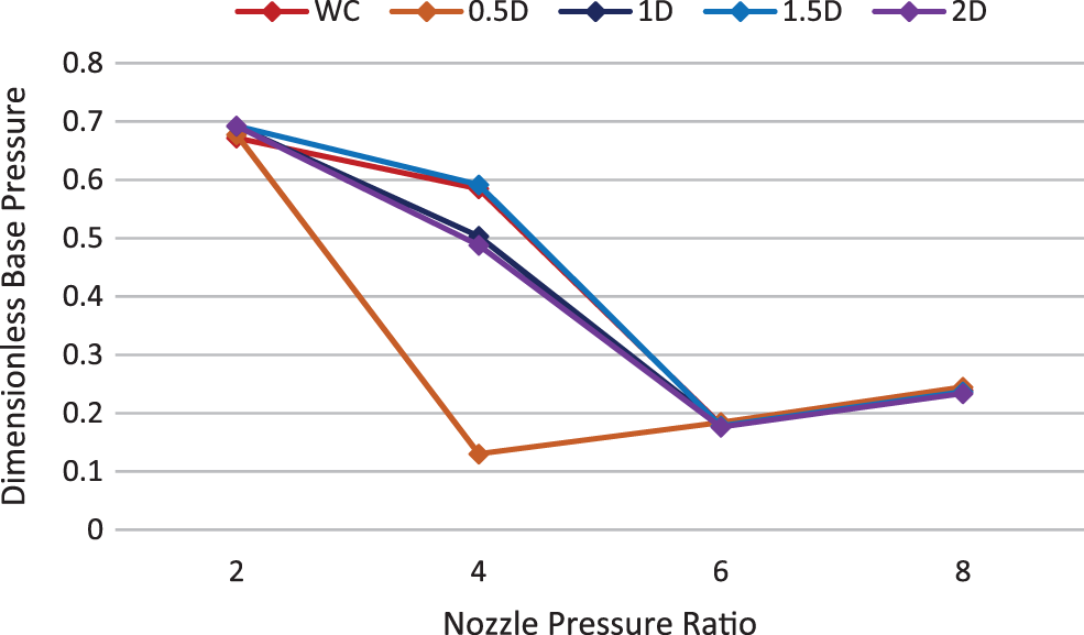
Figure 34: Base pressure vs. NPR, Mach M = 1.4 & L/D = 6
4.7 CFD Analysis Results: Base Pressure for Mach No. 1.6
Figs. 35 to 38 show the base pressure variations with parameters like nozzle pressure ratio, without a cavity, and various cavity locations for Mach number 1.6. it can be seen that the cavity is effective only at NPR = 4. At this NPR, the cavity is effective at some locations in changing the base pressure. At NPR’s 2, 6, and 8, the change in base pressure using the cavity is negligible.
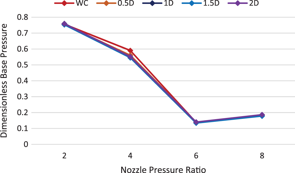
Figure 35: Base pressure vs. NPR at M = 1.6 & L/D = 3

Figure 36: Base pressure vs. NPR at M = 1.6 & L/D = 4

Figure 37: Base pressure vs. NPR at M = 1.6 & L/D = 5

Figure 38: Base pressure vs. NPR at M = 1.6 & L/D = 6
4.8 CFD Analysis Results: Base Pressure for Mach No. 1.8
Figs. 39 to 42 show the base pressure variations with the other parameters of nozzle pressure ratio, without cavity and various cavity locations for Mach number 1.8. It can be seen that the cavity is effective only at NPR = 4. At this NPR, the cavity is effective at some locations in growing the pressure at the base. At NPR’s 2, 6, and 8, the difference in base pressure using the cavity is insignificant.

Figure 39: Base pressure vs. NPR, M = 1.8 & L/D = 3
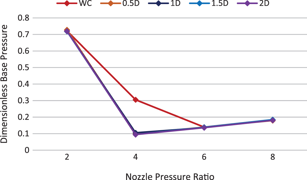
Figure 40: Base pressure vs. NPR, M = 1.8 & L/D = 4
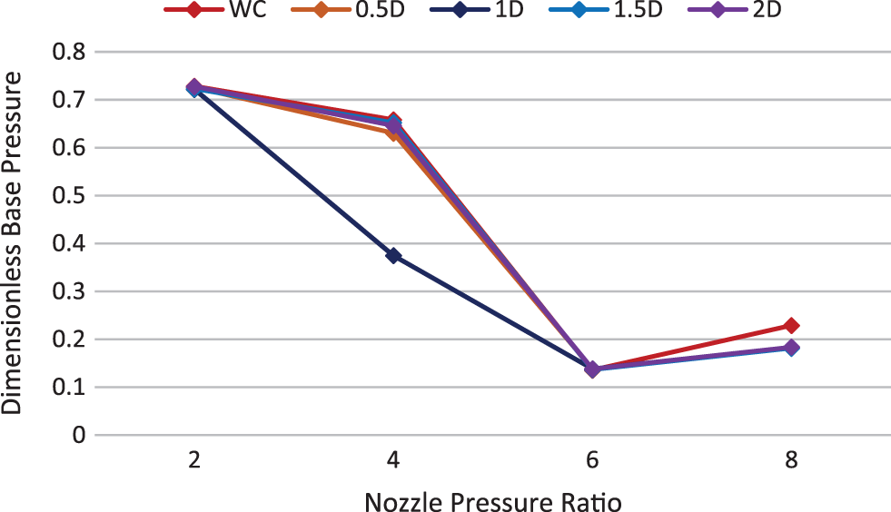
Figure 41: Base pressure vs. NPR, M = 1.8 & L/D = 5
Figure 42: Base pressure vs. NPR, M = 1.8 & L/D = 6
Whenever a control is employed to regulate the flow in a duct with sudden expansion, it is mandatory to examine the impact of the flow management methods on the flow field of the tube. On the researcher’s part, it is necessary to confirm that the passive control does not adversely influence the flow inside the tube. Hence, in this case, we have also considered the effect of the cavities as flow regulators on the wall pressure. Fig. 43 shows that the duct flow field is identical for all the cavity positions except at 2D. Wall pressure is more or less similar, as seen from the figure. Hence, it can be said that the flow in the duct remains identical to the flow without control.
Figure 43: Wall Pressure along the duct at M = 1.4, L/D = 6, and NPR = 4
Based on our results, we can conclude that a cavity can be used to control the base flow. The cavity is adequate to regulate base pressure at NPR = 4. At NPR 2, 6, and 8, the changes in base pressure due to the cavity are insignificant. The reasons for the ineffectiveness of the cavity at these locations are that, at NPR = 2, the nozzle is over-expanded, and the reattachment length is considerable, far away from the base region. Hence there is no interaction between the flow and cavity. Therefore, the cavity is unproductive at a nozzle pressure ratio of 2. On the other hand, the nozzle is highly under-expanded at NPR 6 and 8, and the reattachment length is less than 0.5D. The flow is reattached to the tube before 0.5 times the diameter. The flow is reattached to the duct before 0.5D, and all cavities are placed after 0.5D. Hence, there is no interaction between the base region and the cavity. Thus, the cavities are unsuccessful in increasing base pressure at nozzle pressure ratios 6 and 8. From Taguchi’s main effect plots, it is seen that the parameters, Duct diameter, Mach M, L/D ratio, NPR, and cavity and its location have a substantial effect on controlling base pressure.
Funding Statement: The authors received no specific funding for this study.
Conflicts of Interest: The authors declare that they have no conflicts of interest to report regarding the present study.
References
1. Pandey, K. M., Rathakrishnan, E. (2006). Annular cavities for base flow control. International Journal of Turbo and Jet Engines, 23(2), 113–127. DOI 10.1515/TJJ.2006.23.2.113. [Google Scholar] [CrossRef]
2. Pathan, K. A., Dabeer, P. S., Khan, S. A. (2018). Investigation of base pressure variations in internal and external suddenly expanded flows using CFD analysis. CFD Letters, 17–25. [Google Scholar]
3. Pathan, K. A., Dabeer, P. S., Khan, S. A. (2017a). CFD analysis of effect of flow and geometry parameters on thrust force created by flow from nozzle. 2nd International Conference for Convergence in Technology, pp. 1121–1125. Pune. [Google Scholar]
4. Pathan, K. A., Dabeer, P. S., Khan, S. A. (2017b). CFD analysis of effect of mach number, area ratio and nozzle pressure ratio on velocity for suddenly expanded flows. 2nd International Conference for Convergence in Technology (I2CT), pp. 1104–1110. Pune. [Google Scholar]
5. Khan, S. A., Fatepurwala, M. A., Pathan, K. N., Dabeer, P. S., Baig, M. A. A. (2018). CFD analysis of human powered submarine to minimize drag. International Journal of Mechanical and Production Engineering Research and Development, 8(3), 1057–1066. DOI 10.24247/ijmperdjun2018111. [Google Scholar] [CrossRef]
6. Pathan, K. A., Dabeer, P. S., Khan, S. A. (2019). An investigation of effect of nozzle pressure ratio and control jets location to control base pressure in suddenly expanded flows. Journal of Thermal Engineering, 12(4), 1127–1135. DOI 10.29252/jafm.12.04.29495. [Google Scholar] [CrossRef]
7. Pathan, K. A., Dabeer, P. S., Khan, S. A. (2020). Enlarge duct length optimization for suddenly expanded flows. Advances in Aircraft and Spacecraft Science, 7(3), 203–214. [Google Scholar]
8. Aabid, A., Afghan Khan, S., Baig, M. (2022). Numerical analysis of a microjet-based method for active flow control in convergent-divergent nozzles with a sudden expansion duct. Fluid Dynamics & Materials Processing, 18(6), 1877–1900. DOI 10.32604/fdmp.2022.021860. [Google Scholar] [CrossRef]
9. Saleel, A., Baig, M. A. A., Khan, S. A. (2018). Experimental investigation of the base flow and base pressure of sudden expansion nozzle experimental investigation of the base flow and base pressure of sudden expansion nozzle. IOP Conference Series: Materials Science and Engineering, 370(1), 12052. DOI 10.1088/1757-899X/370/1/012052. [Google Scholar] [CrossRef]
10. Fharukh, A. G. M., Alrobaian, A. A., Aabid, A., Khan, S. A. (2018). Numerical analysis of convergent-divergent nozzle using finite element method. International Journal of Mechanical and Production Engineering and Development, 8(6), 373–382. [Google Scholar]
11. Khan, A., Aabid, A., Khan, S. A. (2018). CFD analysis of convergent-divergent nozzle flow and base pressure control using micro-JETS. International Journal of Engineering & Technology, 7(3), 232–235. DOI 10.14419/ijet.v7i3.29.18802. [Google Scholar] [CrossRef]
12. Khan, S. A., Aabid, A. (2018). CFD analysis of CD nozzle and effect of nozzle pressure ratio on pressure and velocity for suddenly expanded flows. International Journal of Mechanical and Production Engineering Research and Development, 8, 1147–1158. [Google Scholar]
13. Afghan, S., Mohamed, O., Aabid, A. (2021). CFD analysis of compressible flows in a convergent-divergent nozzle. Materials Today: Proceedings, 46, 2835–2842. DOI 10.1016/j.matpr.2021.03.074. [Google Scholar] [CrossRef]
14. Husnina, N., Zuraidi, M., Khan, S. A., Aabid, A., Baig, M. (2023). Passive control of base pressure in a converging-diverging nozzle with area. Fluid Dynamics & Materials Processing, 19(3), 807–829. DOI 10.32604/fdmp.2023.023246. [Google Scholar] [CrossRef]
15. Shen, Z., Yu, S., Zheng, S., Nofal, T. A., Musa, A. et al. (2022). Numerical study of multi-jet with upstream divergent ramp at supersonic cross flow. Aerospace Science and Technology, 127(26), 107689. DOI 10.1016/j.ast.2022.107689. [Google Scholar] [CrossRef]
16. Bai, C., Wang, M., Wu, Z. (2022). Symmetric mach reflection configuration with asymmetric unsteady solution symmetric mach reflection configuration with asymmetric unsteady solution. Chinese Journal of Aeronautics, 469(1), 71. DOI 10.1016/j.cja.2022.06.012. [Google Scholar] [CrossRef]
17. You, A., Be, M. A. Y., In, I. (2022). Control of supersonic compression corner flow using a plasma actuator. Physics of Fluids, 37(7), 073605. DOI 10.1063/5.0096511. [Google Scholar] [CrossRef]
18. Samimy, M., Kim, J. H., Kastner, J., Adamovich, I., Utkin, Y. (2007). Active control of high-speed and high-Reynolds-number jets using plasma actuators. Journal of Fluid Mechanics, 578, 305–330. DOI 10.1017/S0022112007004867. [Google Scholar] [CrossRef]
19. Goparaju, K., Gaitonde, D. V. (2016). Large-eddy simulation of plasma-based active control on imperfectly expanded jets. Journal of Fluids Engineering, 138(7), 1–12. DOI 10.1115/1.4032571. [Google Scholar] [CrossRef]
20. Gaitonde, D. V., Samimy, M. (2011). Coherent structures in plasma-actuator controlled supersonic jets: Axisymmetric and mixed azimuthal modes. Physics of Fluids, 23(9), 95104. DOI 10.1063/1.3627215. [Google Scholar] [CrossRef]
21. Samimy, Mo, Webb, N., Crawley, M. (2018). Excitation of free shear-layer instabilities for high-speed flow control. AIAA Journal, 56(5), 1770–1791. DOI 10.2514/1.J056610. [Google Scholar] [CrossRef]
22. Manigandan, S., Vijayaraja, K. (2018). Mixing characteristics of elliptical jet control with crosswire. IOP Conference Series: Materials Science and Engineering, 310(1), 12163. DOI 10.1088/1757-899X/310/1/012163. [Google Scholar] [CrossRef]
23. Viard, R., Talbi, A., Ghouila-houri, C., Kourta, A., Merlen, A. et al. (2020). Magneto-mechanical micro-valve for active flow control. Sensors and Actuators A: Physical, 316, 112387. DOI 10.1016/j.sna.2020.112387. [Google Scholar] [CrossRef]
24. Narayana, K. P. S. S., Reddy, K. S. (2016). Simulation of convergent divergent rocket nozzle using CFD analysis. IOSR Journal of Mechanical and Civil Engineering, 13(4), 58–65. DOI 10.9790/1684-1304015865. [Google Scholar] [CrossRef]
25. Li, H., Choi, J., Li, B., Kim, I., Heo, J. (2016). Numerical analysis on the gas flow dynamics from a rectangular slot-nozzle for pulse cleaning of filter unit. Powder Technology, 297(1), 330–339. DOI 10.1016/j.powtec.2016.04.040. [Google Scholar] [CrossRef]
26. Yu, N., Jourdain, R., Gourma, M., Shore, P. (2016). Analysis of De-Laval nozzle designs employed for plasma figuring of surfaces. International Journal of Advanced Manufacturing Technology, 87(1–4), 735–745. DOI 10.1007/s00170-016-8502-y. [Google Scholar] [CrossRef]
27. Keir, A. S., Ives, R., Hamad, F. (2018). CFD analysis of C-D nozzle compared with theoretical & experimental data. INCAS Bulletin, 10(2), 53–64. DOI 10.13111/2066-8201.2018.10.2.6. [Google Scholar] [CrossRef]
28. Wang, Y. S., Xu, J. L. (2019). Experimentaland Numerical investigation of an axisymmetric divergent dual throat nozzle. Proceeding of the Institution of Mechanical Engineers, Part: G: Journal of Aerospace Engineering, 234(3), 563–572. DOI 10.1177/0954410019872089. [Google Scholar] [CrossRef]
29. Wang, P. C., McGuirk, J. J. (2013). Large eddy simulation of supersonic jet plumes from rectangular con-di nozzles. International Journal of Heat and Fluid Flow, 43(7), 62–73. DOI 10.1016/j.ijheatfluidflow.2013.06.002. [Google Scholar] [CrossRef]
30. Mousavi, S. M., Roohi, E. (2014). Three dimensional investigation of the shock train structure in a convergent-divergent nozzle. Acta Astronautica, 105(1), 117–127. DOI 10.1016/j.actaastro.2014.09.002. [Google Scholar] [CrossRef]
31. Rao, G. R., Ramakanth, U. S., Lakshman, A. (2013). Flow analysis in a convergent-divergent nozzle using CFD. International Journal of Research in Mechanical Engineering, 1(1), 136–144. [Google Scholar]
32. Najar, N. A., Dandotiya, D., Najar, F. A. (2013). Comparative analysis of K-ε and Spalart-Allmaras turbulence models for compressible flow through a convergent-divergent nozzle. International Journal of Engineering and Science, 2(8), 8–17. [Google Scholar]
33. Salvador, F. J., Jaramillo, D., Romero, J.V., Roselló, M.D. (2017). Using a homogeneous equilibrium model for the study of the inner nozzle flow and cavitation pattern in convergent-divergent nozzles of diesel injectors. Journal of Computational and Applied Mathematics, 309(2), 630–641. DOI 10.1016/j.cam.2016.04.010. [Google Scholar] [CrossRef]
34. Khan, S. A., Aabid, A., Mokashi, I., Al-Robaian, A. A., Alsagri, A. S. (2019). Optimization of two-dimensional wedge flow field at supersonic mach number. CFD Letters, 11, 80–97. [Google Scholar]
35. Khan, S. A., Aabid, A., Ahamed Saleel, C. (2019). CFD simulation with analytical and theoretical validation of different flow parameters for the wedge at supersonic mach number. International Journal of Mechanical & Mechatronics Engineering, 19(1), 170–177. [Google Scholar]
36. Sajali, M. F. M., Ashfaq, S., Aabid, A., Khan, S. A. (2019). Simulation of effect of various distances between front and rear body on drag of a non-circular cylinder. Journal of Advanced Research in Fluid Mechanics and Thermal Sciences, 62(1), 53–65. [Google Scholar]
37. Sajali, M. F. M., Aabid, A., Khan, S. A., Mehaboobali, F. A. G., Sulaeman, E. (2019). Numerical investigation of flow field of a non-circular cylinder. CFD Letters, 11(5), 37–49. [Google Scholar]
38. Aabid, A., Afifi, A., Ahmed Ghasi Mehaboob Ali, F., Nishat Akhtar, M., Afghan Khan, S. (2019). CFD analysis of splitter plate on bluff body. CFD Letters, 11, 25–38. [Google Scholar]
39. Afifi, A., Aabid, A., Afghan Khan, S. (2021). Numerical investigation of splitter plate effect on bluff body using finite volume method. Materials Today: Proceedings, 38(6–7), 2181–2190. DOI 10.1016/j.matpr.2020.05.559. [Google Scholar] [CrossRef]
40. Aabid, A., Nabilah, L., Khairulaman, B., Khan, S. A. (2021). Analysis of flows and prediction of CH10 airfoil for unmanned arial vehicle wing design. Advances in Aircraft and Spacecraft Science, 8(2), 87–109. DOI 10.12989/aas.2021.8.2.087. [Google Scholar] [CrossRef]
41. Kharulaman, L., Aabid, A., Ahmed, F., Mehaboobali, G., Khan, S. A. (2019). Research on flows for NACA, 2412 airfoil using computational fluid dynamics method. International Journal of Engineering and Advanced Technology, 9(1), 5450–5456. DOI 10.35940/ijeat.A3085.109119. [Google Scholar] [CrossRef]
42. Cimbala, M. J. (2014). Taguchi orthogonal arrays. Instrumentation, Measurements, and Statistics. https://www.mne.psu.edu/me345/Lectures/Taguchi_orthogonal_arrays.pdf. [Google Scholar]
Cite This Article
 Copyright © 2023 The Author(s). Published by Tech Science Press.
This work is licensed under a Creative Commons Attribution 4.0 International License , which permits unrestricted use, distribution, and reproduction in any medium, provided the original work is properly cited.
 Downloads
 Citation Tools