
 Submit a Paper
 Propose a Special lssue
 Open Access
ARTICLE

Design and Dynamic Analysis of Pipeline Dredging Devices
1 Jiangsu Key Laboratory of Advanced Manufacturing Technology, Huaiyin Institute of Technology, Huai’an, 223003, China
2 School of Mechanical and Material Engineering, Huaiyin Institute of Technology, Huai’an, 223003, China
* Corresponding Author: Zhong Chen. Email:
(This article belongs to the Special Issue: Computational Mechanics and Fluid Dynamics in Intelligent Manufacturing and Material Processing)
Fluid Dynamics & Materials Processing 2023, 19(6), 1349-1367. https://doi.org/10.32604/fdmp.2023.024513
Received 31 May 2022; Accepted 13 September 2022; Issue published 30 January 2023
 View Full Text
 Download PDF
Abstract
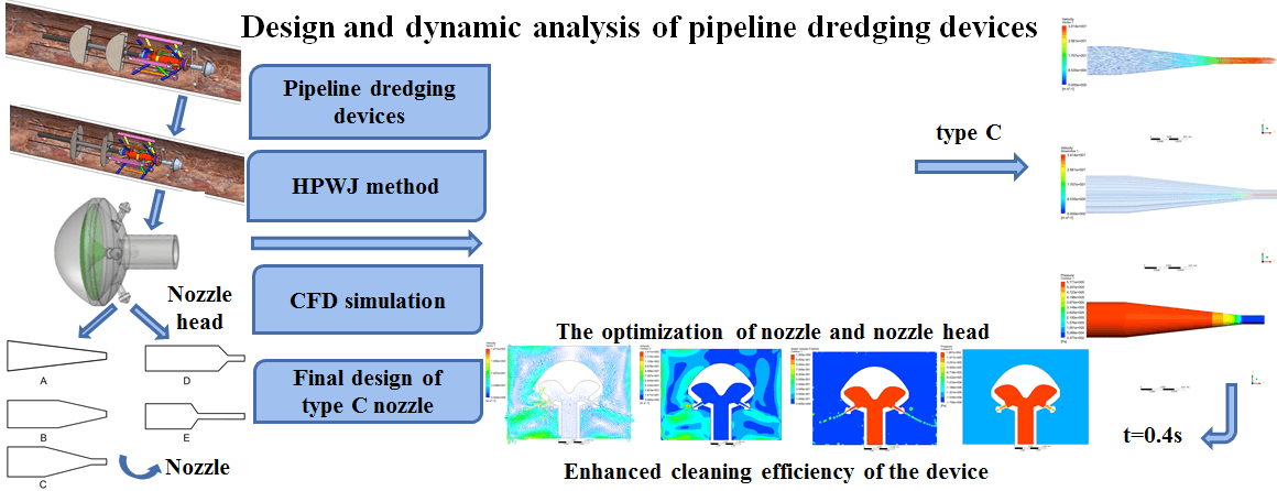
In order to improve the efficiency as well the adaptability and operability of traditional devices used to dredge drainage pipelines a new design is presented here, obtained by matching the structural specifications of a drainage pipeline with the working principle of a high-pressure water jet (HPWJ). To effectively improve the water jet nozzle performances, the nozzle’s structural parameters of the proposed device have been analyzed through Computational fluid dynamics (CFD) simulation. The corresponding behavior of the fluids inside and outside the self-rotational nozzle has been numerically simulated. The final design for the nozzle has been optimized taking into account such results.Graphic Abstract
Keywords
Drainage pipeline blockage is one of the main reasons for waterlogging disasters. Particularly in urban industrial construction, a large amount of concrete sludge flows towards and into drainage pipelines. Although a large fraction of this concrete has already failed, it can still harden on the inner wall of the pipes, which can seriously affect drainage performance during flooding and waterlogging control and, in turn, cause heavy economic losses. Therefore, the pipeline dredging problem needs to be solved urgently [1–3].
The high-pressure water jet (HPWJ) dredging method has been developed. It is extensively applied in many fields such as petroleum engineering, chemical, and electric power industries [4–6]. In water trucks, water is pressed by a high-pressure water pump powered by the water truck engine and is delivered to the water jet nozzle when working. The counterforce generated by the water jet nozzle causes the nozzle and hose to move forward simultaneously, cleaning the pipeline’s inner wall during movement. HPWJ dredging method is appropriate for sewer pipelines with different diameters but not for serious drainage pipelines. At the same time, dredging efficiency is relatively low in this method, while a large amount of cleaning water is required and dredging operation cost is high. Winch dredging is another commonly applied method for pipeline dredging [7]. The key step in this method is to go down the well and make the cables manually and the bamboo slices pass through the pipeline. The working environment in wells is very harsh and brings great inconveniences to workers, and could even cause safety accidents when the pipeline is seriously blocked.
The rapid development of dredging robotics technology for drainage pipelines is mainly divided into two categories: pipeline detection robots which perform a series of pipeline inspection and maintenance operations under the control of the operator [8–10], and pipeline dredging robots, in which dredging function is performed by installing various dredging devices on pipeline dredging robots [11–14]. So far, researchers have generally focused on pipeline detection robots [15–17]. Singh et al. [18] developed a new crawler-type modular pipeline robot with a pipeline diameter adaptive mechanism to make it run in pipelines with different diameters, which had a small and simple structure and easy operation. However, due to the limitations of crawler structures of walking mode, it was not suitable for pipelines with variable diameters. Mills et al. [19] mentioned a wheeled pipeline robot system. The function of adjustability of the robot’s structure for different design requirements can improve its adaptability with pipeline diameter. Due to the short distance between device wheels, it has good obstacle crossing performance, compact structure, strong functionality, etc. [20–22].
For the practical applications of dredging pipeline devices with HPWJ technology, the nozzle and nozzle head, as significant parts, have a considerable impact on the properties of water jets [23]. Different nozzle structures present different hydraulic performances directly affecting the dredging efficiency of water jets [24–26]. Therefore, it is necessary to choose suitable nozzle types and study the key structural parameters of the nozzle in order to improve water jet performance.
This paper developed a dredging method by combining mechanical beating with HPWJ cleaning, and a new dredging device with self-adaptive three-legged walking support. The nozzle and nozzle head, as the main functional components of the dredging device, were numerically simulated and analyzed to obtain optimum nozzle size and improve the structural designs of the nozzle and nozzle head as well as the dredging efficiency of the device. This device could also overcome some existing pipeline dredging difficulties and reduce the labor intensity of dredging workers.
2.1 Machine Structure and Working Principle
2.1.1 Structure and Working Principle
Fig. 1 shows the developed pipeline dredging device, which is divided into dredging, walking and desilting function modules. The walking function module consisted of a walking support bracket, adjustable bracket, roller, slot type link bracket, device housing, ear plate, support bars, connecting rods, support auxiliary brackets, and sliding collars. Among them, adjustable brackets were adopted to adapt to various diameters of drainage pipelines.
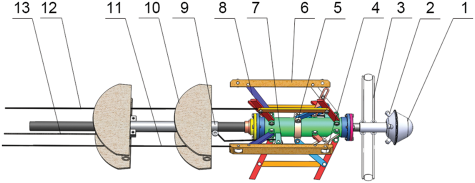
Figure 1: The schematic diagram of device structure: (1) nozzle head, (2) nozzle, (3) flexible hammer, (4) support pulley, (5) axial sliding sleeve ring, (6) walking support, (7) reset pulley, (8) support rod, (9) sediment drainage casing, (10) sediment drainage plate, (11) support nylon rope, (12) reset nylon rope, (13) silt removal nylon rope
Four nozzles were evenly distributed on the nozzle head and had a certain inclination angle with the device’s axial centerline. HPWJ produced a counterforce against the inner wall impact of the pipeline, which forced the nozzle to rotate and generated a forward driving force in the device. Two flexible hammers were installed on the rear seat tube shaft of the nozzle. Nozzle head rotation rotated the flexible hammer to knock the attached dirt and hard scale, eventually making them fall from the inner surface of the pipeline. The device always remained in the middle of the pipe due to the driving force provided by the nozzle head and bracing force from the three walking bracket sets; also, the roller reduced the resistance of device advancement so that it could run smoothly in the pipeline.
In order to effectively avoid blockage accumulating in the pipelines, a sludge discharge module was considered. Two sludge discharge board sets were installed by pivot pins on sludge discharge sleeved on the pipeline. When the device entered the drainage pipeline, the desilting board was in a closed state, as shown in Fig. 2a. When the dredging nylon rope installed on the silt discharge plate was pulled, the silt discharge plate unfolded and moved backward along the water pipeline. Fig. 2b shows the silt discharge plate’s unfolded state. Sludge and dirt in the pipeline were collected and brought to detection wellhead by desilting board cooperating with dredging machine at pipeline outlet to suck the blockage out of the drainage pipeline.

Figure 2: Device structure diagram
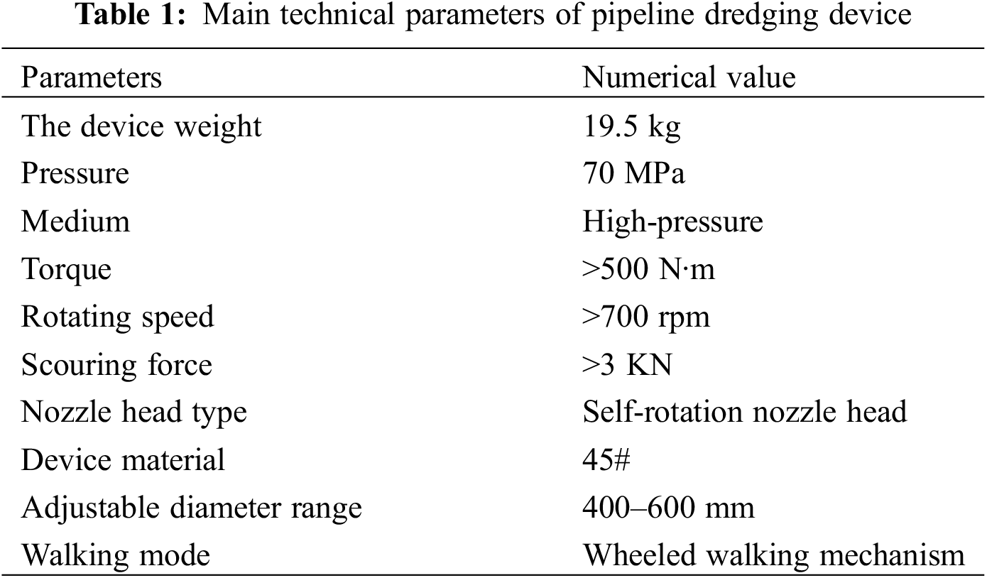
After the sludge was cleaned, the device needed to continue dredging work; therefore, a reset mechanism was designed. The reset pulley of the desilting board was mounted on the bracket backend of the device housing by pivot pins. One end of the nylon rope was fastened to the desilting sleeve front-end, and the other end bypassed the reset pulley and passed to the outside of the drainage pipeline. When reset nylon rope was pulled back, the sludge discharge board was closed and moved along the pipeline to reset. At the same time, the bracket backend was tightened up to release device fixation. High-pressure water was injected into the device to work again. The main technical parameters of the device are summarized in Table 1.
2.2 Nozzle Head Working Theory and Structural Design
2.2.1 Nozzle Head Selection and Design
In this research, high-pressure water was applied as a dredging medium, and impact force was induced by HPWJ impinging on the pipeline inner wall. Therefore, structural design requirements of the nozzle head included high cleaning efficiency, low-pressure loss, low vibration, reasonable nozzle distribution, material saving, high wear resistance, and low flow resistance.
Currently, common nozzle head types on the market include fixed, rotary, and fluid-conducting nozzle heads. In rotating nozzle heads, the jet shape has obvious expansion and a great impact which result in the formation of a large impact area so that sludge and blockage on the inner wall of the pipeline can be effectively cleaned, but they have a relatively complicated structure. Therefore, to meet nozzle structure design requirements, a self-rotation nozzle head was selected, composed of a nozzle head front cover, a nozzle head back cover, and a deflector, a nozzle, and other necessary parts. The four nozzles were evenly distributed on the nozzle head with a certain inclination angle. Fig. 3 shows the structure of a rotating nozzle head.

Figure 3: 3D model of a rotating nozzle head
The rotating nozzle used in this research lost a fraction of its energy when working. When HPWJ impinged on the pipe’s inner wall, the direction and magnitude of its velocity, and therefore its momentum, were changed. In calculations, the device’s water jet was considered an ideal fluid, and jet velocity at the nozzle was not changed while its direction changed. The calculation equation of the impact force generated by the water jet was stated as:
where
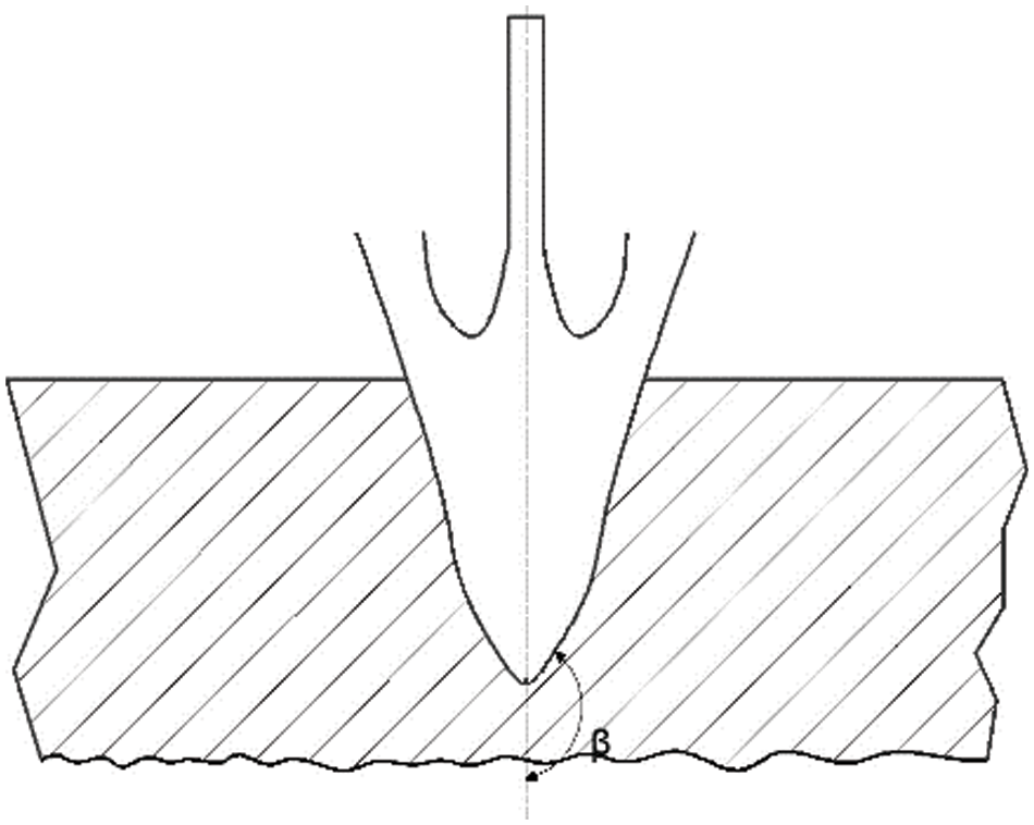
Figure 4: Schematic diagram of reflection angle
When the water jet impact force on the part surface was at maximum theoretical value, it was seen from Eq. (1) that the calculated surface impact force value was larger than the actual value because the energy lost by air friction with water jet was not considered in the calculation process. In addition, it could be concluded from target distance theory that the theoretical value did not take into account the influence of the distance between the water jet nozzle outlet and pipeline inner wall; so, there was a certain deviation between calculated and actual values [27–29]. Therefore, selecting reasonable HPWJ parameters such as working pressure, target distance, and flow rate to calculate water jet impact force on inner pipe wall can effectively hit the dirt attached to inner pipe surface without causing damage to the pipe material.
The structure and diameters of the nozzle had different effects on the flow field distribution and nozzle performance of HPWJ. Therefore, choosing a reasonable nozzle type could provide a better jet effect. Nozzle shape can be generally divided into cone-shaped, fan-shaped, and special-shaped types, among which fan-shaped and cone-shaped nozzles are often employed for cleaning. Fan-shaped nozzles have a flat shape, compact structure, and wide spray range, so the generated water jet is also flat, generating an atomization effect. Fan-shaped nozzles are used in mechanical equipment such as continuous casting machines, which need cooling as well as oil injection and lubrication processes such as high-speed wire rods. They are also often employed in air purification, eco-friendly cleaning, and pesticide spraying. Conical nozzles have the advantages of simple geometric structure, high clustering, good processing technology, and low cost compared with other nozzles and can reduce fluid blockage problems in the nozzle. Conical nozzles are generally applied for water jet cleaning with high requirements to complete the cleaning task. Compared with conical nozzles, fan-shaped nozzle have much larger jet diffusion angles, creating more uniform water jet with a much lower impact force, and insufficient impact force on the dirt attached to the part surface; therefore, they are not suitable for pipeline dredging tasks. When considering the water jet’s effect, simple structure, and high jet pressure in this research, a conical nozzle was used, and the three-dimensional model of that nozzle structure is shown in Fig. 5.
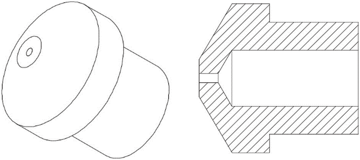
Figure 5: The schematic diagrams of nozzle structure
2.3.1 The Main Parameters of the Nozzle
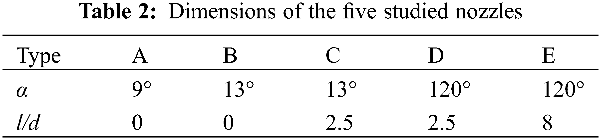
Many factors affect conical nozzle performance, such as nozzle outlet diameter, nozzle transitional section length l, nozzle length-to-diameter ratio l/d, nozzle contraction angle α, and nozzle flow coefficient [30,31]. These parameters are shown in Fig. 6. In order to improve nozzle working performance, this research provided a design based on the specific nozzle structure and diameter characteristics. Five types of conical nozzles were presented in this work to study the influences of contraction angle and length-to-diameter ratio on nozzle performance to analyze and optimize nozzle structure. The five nozzles used in this research are shown in Fig. 7. Nozzle inlet diameter was 8 mm, outlet diameter was 2 mm, and the total nozzle length was set to 40 mm. The inner dimensions of the above five nozzles are given in Table 2.
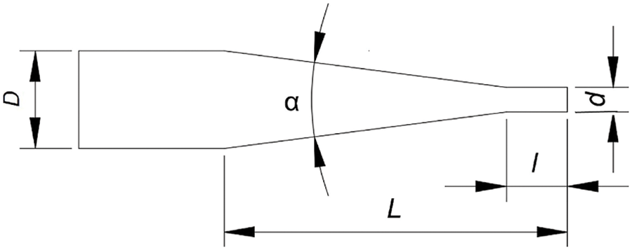
Figure 6: Nozzle parameters
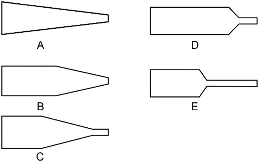
Figure 7: The shapes of the five nozzle types used in this work
2.4 Nozzle Structure Optimization
In order to improve the cleaning and dredging efficiencies of HPWJ, a reasonable mounting angle was required, as shown in Fig. 8. For too small θ values, the water jet sprayed by the nozzle could not have an impact on the inner wall. For too high θ values, for example, 90°, a vertical impact was generated, which did not provide a suitable driving force for the device. Moreover, when the inclination angle was 60°, the backflow phenomenon caused by the water jet was the slightest. When one considers the flushing effect of the pipeline inner wall and reaction force, the inclination value was considered to be in the range of θ as 60°.
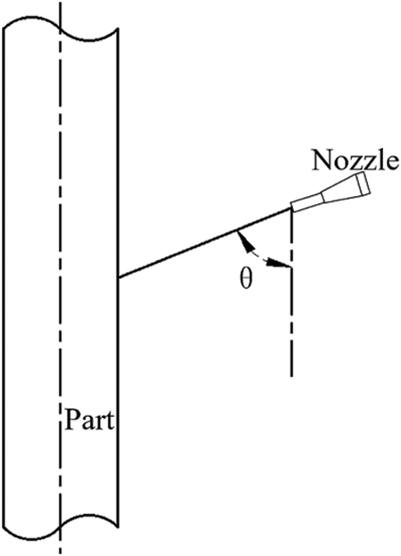
Figure 8: The impact angle of the nozzle
3 Numerical Simulation Analysis of Nozzle
This paper mainly studies the incompressible fluid flow process of nozzle jet and obtained jet equation from fluid continuity equation [32–35].
Continuity equation of incompressible fluid was:
And momentum equation was:
Since the jet field was in a highly turbulent state, the turbulence model of the flow field inside the nozzle adopted a standard
where
3.2 Numerical Simulation of Nozzle
3.2.1 Geometric Modeling and Meshing
SolidWorks software was used to construct five nozzle types, and the reconstructed 3D model was saved in X_T format and imported into GAMBIT. In order to extract the nozzle fluid domain, a face closed geometric model was developed by setting caps to specify the boundaries of the fluid domain so that the fluid field in the model was in a completely closed state. The fluid inlet and outlet are shown in Fig. 9. To precisely obtain the distributions of different nozzles’ internal and external flow fields and ensure the accuracy and speed of subsequent calculations, the nozzle fluid area grid was constructed in GAMBIT into unstructured tetrahedral meshes. After division, the number of grid nodes was 24,644, the number of grid elements was 88,479, and the average grid quality was 0.74199, which met the requirements of numerical calculations. Fig. 10 shows the grid quality distribution diagram.
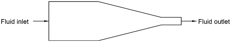
Figure 9: Fluid inlet and outlet construction
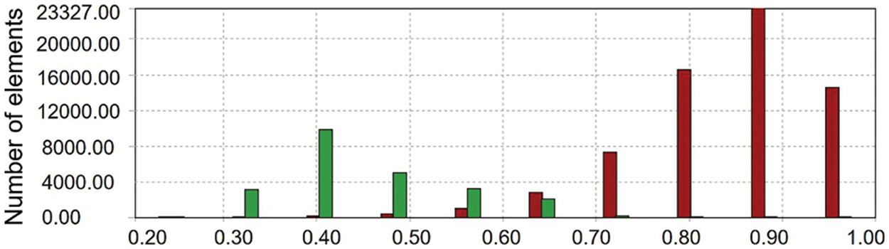
Figure 10: The quality of mesh
In this research, the device used HPWJ to dredge and remove silt on the pipeline inner wall. The density and viscosity of water were 1000 kg/m3 and 0.001 Pa∙s., respectively. Velocity-inlet boundary condition was chosen for inlet, and jet inlet velocity was 2 m/s. Pressure-outlet was considered as an exit boundary condition, and standard atmosphere pressure was set. When neglecting the slip between medium water and nozzle inner wall contact surface, the no-slip boundary condition was defined at walls.
3.2.3 Solution Method and Model Selection
The Fluent16.0 in the ANSYS Workbench software package was applied to simulate and analyze the flow field. According to simulation results, the influence rules of flow filed with its various parameters could be observed so as to optimize the nozzle structure. The SIMPLE algorithm was adopted, a second-order model was selected by pressure discrete algorithm, and the solution and calculation were carried out in Fluent16.0.
4.1 Simulation Model and Analysis of Nozzle
The internal flow field, velocity vector and pressure nephograms of the five nozzles were simulated, as shown in Fig. 11.
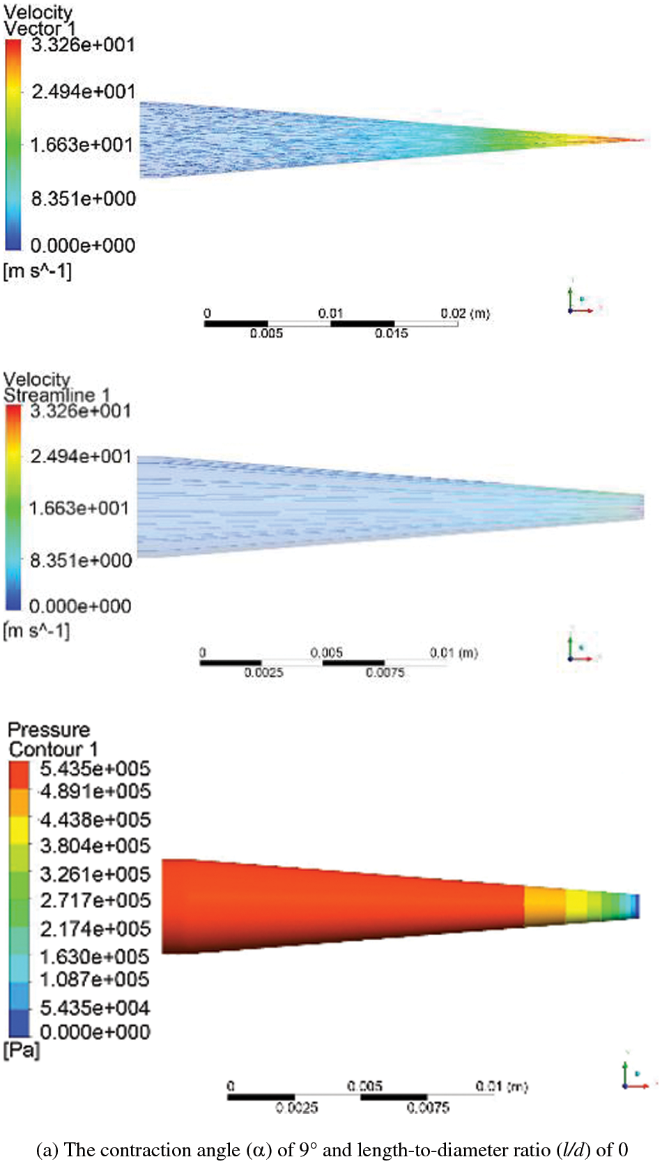

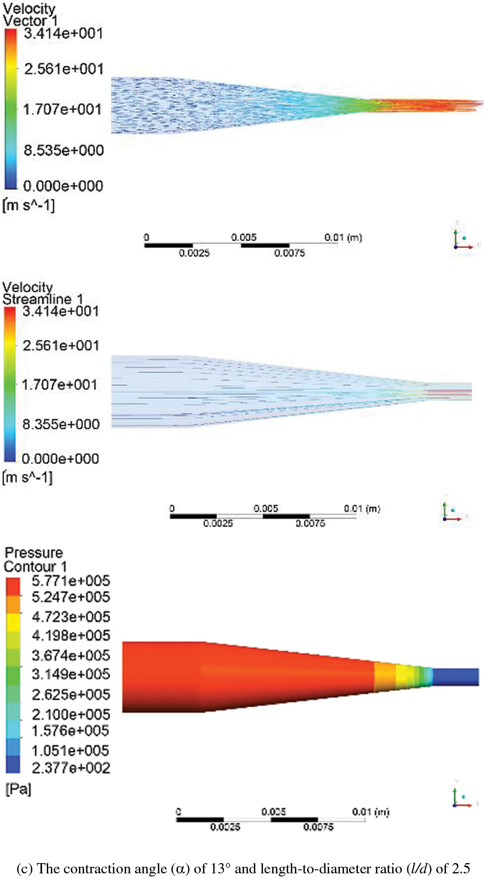


Figure 11: Nephograms of flow field, velocity vector and pressure of five nozzles
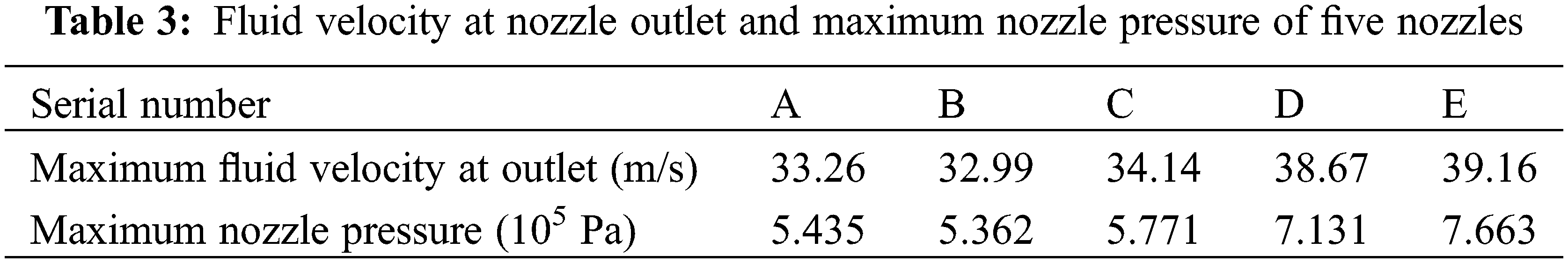
According to the results of the flow nephograms analysis, the maximum fluid velocity at nozzle outlet and maximum nozzle pressure were obtained, as shown in Table 3.
4.1.1 Internal Flow Field Distribution Nephograms
The first column in Fig. 11 shows the flow field distributions of five nozzle shapes. Flow field distribution inside the nozzles was also different for different contraction angles and length-to-diameter ratios. Considering the contraction angle effect on flow field distribution, when the contraction angle was 9°, the nozzle flow field distribution was more uniform. When the contraction angle was increased to 13°, flow field distribution inside the nozzle changed gently. A sharp contraction of flow field distribution was also observed at the junction of the conical contraction section and cylindrical transition section due to the leaping of 120° contraction angle. As the contraction angle was increased, the internal structure of the nozzle was changed, which changed the water jet direction after contacting the end surface of the contraction section, and the local resistance inside the nozzle was increased. At the same time, turbulence kinetic energy inside the nozzle was affected, which caused energy loss. When the contraction angle was too large, the water jet flow direction changed suddenly, resulting in higher energy loss. When considering the influence of length-to-diameter ratio on flow field distribution, cylindrical transition section length was obtained by l/d ratio. When the geomatics design of l/d ratio was 0, the nozzle had no cylindrical transition section, and the internal flow field sharply shrank near the nozzle outlet section. As the ratio increased to 2.5, flow field distribution in the nozzle was great. This happened because the l/d ratio was increased by increasing cylindrical transition section length, which corresponded to reducing turbulent flow patterns. However, too large a length-to-diameter ratio led to a large frictional drag, resulting in serious energy loss. As shown in Fig. 11e, flow field distribution in the nozzle was not ideal, which had an l/d ratio of 8.
4.1.2 Nozzle Velocity Distribution Nephograms
As shown in column 2 of Fig. 11, comparing the velocity vector distributions of the internal flow fields of five nozzles, the influences of contraction angles and length-to-diameter ratios on velocity vector distribution in the nozzle were determined. It was seen that the velocity of the inlet and contraction sections of the nozzle was not changed significantly, but the velocity at the nozzle outlet increased gradually. Figs. 11a and 11b showed that when the l/d ratio was constant, nozzle outlet velocity with a contraction angle of 9° was relatively high. As shown in Fig. 11, the influence of l/d ratio on velocity distribution varied inside the five nozzles. This was because the nozzle’s length-to-diameter ratio directly affected the nozzle’s flow resistance and flow coefficient. It also mainly affected the efflux of the nozzle. According to Figs. 11c–11e, the introduction of the nozzle transition section caused sudden velocity change in the radial face connected between the nozzle contraction section and transition section. Velocity distribution nephograms presented the same trend that longer nozzle transition sections elongated high-speed section of water jet inside the nozzle, in which the l/d ratio was 2.5. According to Fig. 11e, when the l/d ratio was too large, the velocity of nozzle l/d increased accordingly along the central axis. Still, it changed rapidly along a longitudinal direction, which did not effectively improve cleaning efficiency. It was seen from Fig. 11 and Table 3 that the nozzle outlet velocity of type C was higher when the contraction angle was 13°.
4.1.3 Nozzle Pressure Distribution Nephograms
Internal pressure distribution nephograms of five nozzles were obtained, as shown in column 3 of Fig. 11. It was seen that the internal pressures of the five nozzles indicated decreasing trends. When the contraction angle was small, the change of pressure magnitude inside the nozzle was evenly distributed. As was seen from pressure distribution nephograms in Fig. 11 and Table 3, when the nozzle contraction angle reached 120°, the nozzle structure was changed obviously. Simultaneously, nozzle pressure underwent a dramatic change, causing water jet to impact on cylindrical section wall that contributed to flow stabilization. Meanwhile, the length-to-diameter ratio of the type E nozzle was 9, and the long transition section led to friction loss inside the nozzle, which was not conducive to stabilizing fluid morphology. As shown in Fig. 11, there was an obvious negative pressure area near the outlet section of the nozzle. When the ratio of length to diameter was 2.5, the pressure distribution of the flow field in the nozzle was uniform, streamline distribution was more reasonable, and the water jet could flow from nozzle inlet to outlet smoothly.
From the simulation and comparison analyses of the internal flow field of the above five nozzles, it was seen that when contraction angle and l/d ratio were both small, it was beneficial to decrease water jet energy loss, thereby obtaining a water jet with higher stability. In summary, comparing the simulation results of the five nozzles showed that the type C nozzle had the best performance. Specific parameters were as follows: α was 13°, l/d was 2.5, the maximum pressure in the nozzle was 5.771
4.2 Numerical Simulation Analysis of Nozzle Head
Type C nozzle was selected and installed on the nozzle head with an impact angle of 60° and nozzle inlet velocity was set to 5 m/s. The flow medium in the nozzle was set as water, and the environmental medium was air inside the pipe. Due to intense momentum exchange and turbulent diffusion between the above two mediums (water and air), the velocities of the two-phase medium were not equal, so the multiphase volume of fluid (VOF) model was selected to simulate current flows. Also, a two-phase numerical simulation was carried out. The obtained results at the flow times of 0.2 and 0.4 s are shown in Fig. 12.
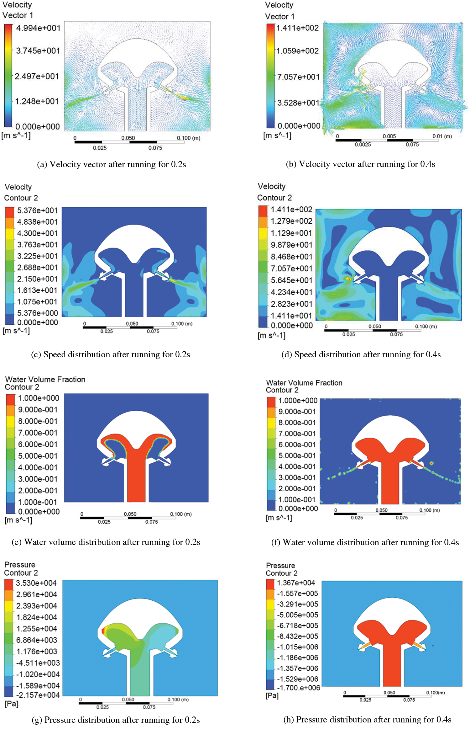
Figure 12: Dynamic analysis nephograms of nozzle head
Water was pressed into the nozzle head from high-pressure water wheel outside the pipeline to wash the inner wall of drainage pipeline. Since the nozzle head was placed horizontally in the pipeline, gravity action had to be considered, and the direction of gravity needed to be set along the negative direction of the X-axis. After water flow was ejected, frictions developed between water and air in the pipeline, so that the non-submerged water jet appeared as a gas-liquid two-phase jet. When flow time was 0.2 s, the water jet just contacted the air. As was seen from Figs. 12a, 12c, 12e and 12g, the jet had a good velocity characteristic at the exit with a large axial velocity along the jet and a uniform velocity gradient distribution perpendicular to the jet axial direction. At this time, water jet filled the nozzle interior, nozzle head internal pressure was evenly distributed, and the pressure on the inner wall of the nozzle head along the negative direction of the X-axis was relatively high. At the flow time of 0.4 s, it was seen from Figs. 12b and 12d that water jet velocity raised rapidly. Under the influence of gravity, water jet velocity along the negative X-axis direction was larger than that along a positive direction. Also, the velocity vector at the nozzle outlet presented a divergent distribution. According to Figs. 12f and 12h, the water jet had a good cluster property and a long range. From the analysis results, water jet velocity at the nozzle outlet was 53.76 m/s at 0.2 s, and the maximum jet velocity generated by the nozzle was 141 m/s at 0.4 s. Higher jet velocities could produce enough impact force to realize the flushing of the inner wall of the pipeline. At this time, pressure distribution in the nozzle head was uniform, which met design requirements.
In summary, a type C nozzle was selected, which was assembled at the inclination angle of 60° on the nozzle head. HPWJ injection had better stability and higher velocity. Therefore, stronger influence on the pipeline walls could provide a greater driving force to the device to achieve a better cleaning effect of desilting.
According to the present situation and some existing problems of urban drainage pipeline dredging, the author has put forward the method of combining mechanical tapping with high-pressure water cleaning and designed a new type of pipeline dredging device, which was convenient to use and moved with good dredging effect, high safety and a high degree of automation. The computational fluid dynamics (CFD) method was applied to simulate and analyze the nozzle and nozzle head to find optimum nozzle parameters, including the convergent angle of nozzle contraction section and the ratio of length to diameter. Jet characteristics were analyzed with the transient flow in the nozzle and nozzle head. The main conclusions were as follows:
(1) Three sets of adjustable walk structures were adopted to improve the pipeline suitability of the device. Also, flexible hammer and reset mechanisms were also included that could collect and clean clogged chips after dredging in the pipeline with high-pressure water, providing a counterforce against the impact of the inner wall of the pipeline and driving the device forward.
(2) In this paper, five nozzles’ internal flow field characteristics with different parameters were studied and analyzed. Velocity was gradually increased while pressure was decreased along the radial direction from injected inside to injected periphery. The influence of contraction angle α and length-to-diameter ratio l/d of the nozzle on the nozzle jet properties were investigated. By increasing contraction angle and length-to-diameter ratio, velocity and pressure were increased. When the contraction angle value was constant, a great increase in length-to-diameter ratio led to a sharp increase of vertical direction velocity. The results showed that the nozzle with α of 13° and l/d of 2.5 had the best performance, the maximum pressure in the nozzle was 5.77105 Pa and water jet velocity at the nozzle outlet was 34.14 m/s. Better jet flow dredging effect can be achieved by an inclination angle of 60° of the nozzle head. Therefore, the nozzle was optimized to improve the stability of HPWJ and enhance the cleaning efficiency of the device, avoiding the waste of resources caused by repeated trial production.
Funding Statement: This work was supported by the Program for Distinguished Talents of Six Domains in Jiangsu Province of China (No. GDZB-062), and the Jiangsu Province Industry University Research Cooperation Prospective Study Project (No. BY2016061-14) and the Jiangsu Province Graduate Research and Practice Innovation Program Project (SJCX22_1671).
Conflicts of Interest: The authors declare that they have no conflicts of interest to report regarding the present study.
References
1. Wang, Z. F. (2018). The cause analysis and countermeasure research on urban water logging in Ningbo. Current Urban Studies, 6(3), 340–347. DOI 10.4236/cus.2018.63018. [Google Scholar] [CrossRef]
2. Lu, S. Q., Wang, C. F., Wang, W., Li, M. J., Zhang, D. T. (2021). Analysis on the shape and impact pressure of the high-pressure water jet during the hydraulic flushing cavity technique. Geofluids, 2021(1–4), 1–16. DOI 10.1155/2021/7496540. [Google Scholar] [CrossRef]
3. Rathi, M. K., Rajiv, P. D. (2011). Study of problems and corrective actions of urban drainage network. Proceeding of International Conference on Electric Technology and Civil Engineering (ICETCE), pp. 22–24. Lushan, China. [Google Scholar]
4. Urazmetov, O., Cadet, M., Teutsch, R., Antonyuk, S. (2021). Investigation of the flow phenomena in high-pressure water jet nozzles. Chemical Engineering Research and Design, 165(14), 320–332. DOI 10.1016/j.cherd.2020.10.030. [Google Scholar] [CrossRef]
5. Yang, Z. Q., Dou, L. M., Liu, C., Xu, M. T., Lei, Z. et al. (2016). Application of high-pressure water jet technology and the theory of rock burst control in roadway. International Journal of Mining Science and Technology, 26(5), 929–935. DOI 10.1016/j.ijmst.2016.05.037. [Google Scholar] [CrossRef]
6. Sarkar, M. K. (2021). Role of inland dredging for integrated water management. Advances in Water Resources Management for Sustainable Use, 131, 57–71. DOI 10.1007/978-981-33-6412-7. [Google Scholar] [CrossRef]
7. Wang, J., Liu, G. H., Wang, J., Xu, X., Shao, Y. T. et al. (2021). Current status, existent problems, and coping strategy of urban drainage pipeline network in China. Environmental Science and Pollution Research, 28(32), 43035–43049. DOI 10.1007/s11356-021-14802-9. [Google Scholar] [CrossRef]
8. Parween, R., Muthugala, M. A., Heredia, M. V., Elangovan, K., Elara, M. R. (2021). Collision avoidance and stability study of a self-reconfigurable drainage robot. Sensors, 2021(11), 3744. DOI 10.3390/s21113744. [Google Scholar] [CrossRef]
9. Gargade, A., Tambuskar, D., Thokal, G. (2013). Modelling and analysis of pipe inspection robot. International Journal of Emerging Technology and Advanced Engineering, 3(5), 120–126. [Google Scholar]
10. Prashanth, B. N., Karthik, V., Karthikeyan, S., Raviteja, P. (2015). Design and development of drainage inspection and anti-clogging robot. Applied Mechanics and Materials, 813–814, 978–982. DOI 10.4028/www.scientific.net/AMM.813-814.978. [Google Scholar] [CrossRef]
11. Satheesh Kumar, G., Arun, D. (2021). In-pipe robot mechanisms—State-of-the-art review. Trends in Mechanical and Biomedical Design, 2021, 703–713. DOI 10.1007/978-981-15-4488-0. [Google Scholar] [CrossRef]
12. Wu, P., Liu, M., Gong, A., Zhuang, E. (2018). Finite element analysis of municipal drainages dredging robot. 2018 6th International Conference on Mechanical, Automotive and Materials Engineering (CMAME), pp. 37–40. IEEE, Hong Kong, China. [Google Scholar]
13. Mishra, D., Yadav, R. S., Agrawal, K. K. (2020). Kinematic modelling and emulation of robot for traversing over the pipeline in the refinery. Microsystem Technologies, 26(3), 1011–1020. DOI 10.1007/s00542-019-04615-9. [Google Scholar] [CrossRef]
14. Parween, R., Palanisamy, P. A., Wen, T. Y., Terntzer, D. N., Elara, M. R. (2022). Estimation of sloshing motion in a wheel-based drain inspection robot. 2022 IEEE 12th Annual Computing and Communication Workshop and Conference (CCWC), pp. 0688–0693. Las Vegas, NV, USA. [Google Scholar]
15. Li, Z. X., Li, Z. H., Li, Y., Wang, W. (2010). Development of the self-adaptive pipeline cleaning robot. Advanced Materials Research, 97, 4482–4486. DOI 10.4028/www.scientific.net/AMR.97-101.4482. [Google Scholar] [CrossRef]
16. Du, Y., Zhu, Q., Ghauri, S., Zhai, J., Jia, H. et al. (2012). Progresses in study of pipeline robot. Proceedings of International Conference on Modelling, Identification and Control, pp. 808–813. IEEE, Wuhan, China. [Google Scholar]
17. Verma, A., Kaiwart, A., Dubey, N. D., Naseer, F., Pradhan, S. (2022). A review on various types of in-pipe inspection robot. Materials Today: Proceedings, 50, 1425–1434. [Google Scholar]
18. Singh, P., Ananthasuresh, G. K. (2012). A compact and compliant external pipe-crawling robot. IEEE Transactions on Robotics, 29(1), 251–260. DOI 10.1109/TRO.2012.2214560. [Google Scholar] [CrossRef]
19. Mills, G. H., Jackson, A. E., Richardson, R. C. (2017). Advances in the inspection of unpiggable pipelines. Robotics, 6(4), 36. DOI 10.3390/robotics6040036. [Google Scholar] [CrossRef]
20. Selvarajan, A., Kumar, A., Sethu, D., Ramlan, M. (2019). Design and development of a snake-robot for pipeline inspection. 2019 IEEE Student Conference on Research and Development (SCOReD), IEEE, Bandar Seri Iskandar, Malaysia. [Google Scholar]
21. Yang, X., Bai, P., Shen, X., Li, Z., Yin, Q. (2018). Design and modeling of a walking mechanism for the self-adapting pipeline robot. IOP Conference Series: Earth and Environmental Science, 186(5), 012035. DOI 10.1088/1755-1315/186/5/012035. [Google Scholar] [CrossRef]
22. Ye, C., Liu, L., Xu, X., Chen, J. (2015). Development of an in-pipe robot with two steerable driving wheels. IEEE International Conference on Mechatronics and Automation (ICMA), pp. 1955–1959. IEEE, Beijing, China. [Google Scholar]
23. He, L., Liu, Y., Shen, K., Yang, X., Ba, Q. et al. (2021). Numerical research on the dynamic rock-breaking process of impact drilling with multi-nozzle water jets. Journal of Petroleum Science and Engineering, 207(2), 109145. DOI 10.1016/j.petrol.2021.109145. [Google Scholar] [CrossRef]
24. Chen, L. H., Cheng, M. Z., Cai, Y., Guo, L. W., Gao, D. (2022). Design and optimization of high-pressure water jet for coal breaking and punching nozzle considering structural parameter interaction. Machines, 10(1), 60. DOI 10.3390/machines10010060. [Google Scholar] [CrossRef]
25. Roselita, S. N. L., Rahman, A., Rahman, M. T. A., Kamarrudin, N. S., Amin, N. A. M. (2021). Design analysis of high-pressure pure water jet nozzle for cutting industry. AIP Conference Proceedings, 2347(1), 020141. [Google Scholar]
26. Shen, C. M., Lin, B. Q., Meng, F. W. (2011). Structure optimization and application of conical convergence high-pressure jet nozzle. Advanced Materials Research, 228, 1001–1006. DOI 10.4028/www.scientific.net/AMR.228-229.1001. [Google Scholar] [CrossRef]
27. Maasberg, W. (2012). Commercial-industrial cleaning, by pressure-washing, hydro-blasting and UHP-jetting: The business operating model and how-to manual for 450 specific applications. Germany: Springer Press. [Google Scholar]
28. Abulimiti, A., Zheng, C., Liu, Y., Pang, H., Pang, D. et al. (2021). Study on the impacting performance of a self-excited oscillation pulsed jet nozzle. Journal of Petroleum Science and Engineering, 207(7), 109120. DOI 10.1016/j.petrol.2021.109120. [Google Scholar] [CrossRef]
29. Sun, Y., Fu, Y., Chen, B., Lu, J., Deng, W. (2021). Numerical simulation and experimental study on flow field in a swirl nozzle. Shock and Vibration, 2021(22), 1–9. DOI 10.1155/2021/6626715. [Google Scholar] [CrossRef]
30. Zhou, J. Z., Xu, X. P., Chu, W. J., Zhu, Z. C., Chen, Y. H. et al. (2013). Analysis and simulation of the fluid field in thermal water-jet nozzle based on ANSYS FLUENT & ICEM CFD. Applied Mechanics and Materials, 423, 1677–1684. DOI 10.4028/www.scientific.net/AMM.423-426.1677. [Google Scholar] [CrossRef]
31. Ghassemieh, E., Versteeg, H. K., Acar, M. (2006). The effect of nozzle geometry on the flow characteristics of small water jets. Proceedings of the Institution of Mechanical Engineers, Part C: Journal of Mechanical Engineering Science, 220(12), 1739–1753. DOI 10.1243/0954406JMES430. [Google Scholar] [CrossRef]
32. Zhang, S., Tao, X., Lu, J., Wang, X., Zeng, Z. (2015). Structure optimization and numerical simulation of nozzle for high pressure water jetting. Advances in Materials Science and Engineering, 2015(4), 1–8. DOI 10.1155/2015/732054. [Google Scholar] [CrossRef]
33. Deng, W., Zhang, R., Xu, G., Li, L., Tang, Q. et al. (2019). The influences of the nozzle throat length and the orifice grooving degree on internal flow field for a multi-entry fan nozzle based on FLUENT. Engineering, 11(11), 777–790. DOI 10.4236/eng.2019.1111052. [Google Scholar] [CrossRef]
34. Banat, R. A. A., Adam, A. M. H., Younis, O. B. A. I., Elsir, D. A. N. I. A. (2018). The effects of nozzle shape on the flow characteristics–A review. European Academic Research, 5(8), 4874–4886. [Google Scholar]
35. Guha, A., Barron, R. M., Balachandar, R. (2011). An experimental and numerical study of water jet cleaning process. Journal of Materials Processing Technology, 211(4), 610–618. DOI 10.1016/j.jmatprotec.2010.11.017. [Google Scholar] [CrossRef]
Cite This Article
 Copyright © 2023 The Author(s). Published by Tech Science Press.
This work is licensed under a Creative Commons Attribution 4.0 International License , which permits unrestricted use, distribution, and reproduction in any medium, provided the original work is properly cited.
 Downloads
 Citation Tools