
 Submit a Paper
 Propose a Special lssue
 Open Access
ARTICLE

Assessment of the Mechanical Properties of Carbon-Fiber Heating Cables in Snow and Ice Melting Applications
1
School of Civil Engineering and Environment, Hubei University of Technology, Wuhan, 430068, China
2
Xiangyang Industrial Institute of Hubei University of Technology, Xiangyang, 441100, China
* Corresponding Author: Zhi Chen. Email:
(This article belongs to the Special Issue: Advances in Solid Waste Processing and Recycling Technologies for Civil Engineering Materials)
Fluid Dynamics & Materials Processing 2023, 19(9), 2267-2288. https://doi.org/10.32604/fdmp.2023.028652
Received 30 December 2022; Accepted 14 March 2023; Issue published 16 May 2023
 View Full Text
 Download PDF
Abstract
The use of carbon-fiber heating cables (CFHC) to achieve effective melting of snow and ice deposited on roads is a method used worldwide. In this study, tensile and compressive tests have been conducted to analyze the mechanical properties of the CFHC and assess whether the maximum tensile and compressive strengths can meet the pavement design specifications. In order to study the aging produced by multiple cycles of heating and cooling, in particular, the CFHC was repeatedly heated in a cold chamber with an ambient temperature ranging between −20°C and +40°C. Moreover, to evaluate how the strength of the pavement is affected by its presence, the CFHC was embedded at different depths and concrete blocks with different curing ages were subjected to relevant compression and splitting tensile tests. Numerical simulations based on the ANSYS software have also been performed and compared with the outcomes of the static loading tests. The results show that the CFHC embedded in the concrete does not affect the compressive splitting tensile strengths of the pavement. Overall, the CFHC meets the conditions required for continued use for road ice melting applications.Graphic Abstract
Keywords
Investigation shows that in the cold winter, snow on roads will have a greater impact on the efficiency of transportation. The heavy snow on the road will cause frequent traffic accidents, resulting in huge economic losses and even endangering safety of lives. Currently, de-icing salt and manual mechanical snow removal methods are widely used around the world to solve the problem of snow accumulation on pavements. The chloride in de-icing salt can seriously affect the durability of concrete pavement, corrode pavement infrastructure in large quantities and reduce the service life of the pavement. De-icing salt penetrates into the pavement and the soil around the road, which can damage the surrounding ecological environment. In reference [1], manual mechanical snow removal methods are time-consuming and laborious and also affect the normal operation of road traffic. Countries around the world have done a lot of research on how to quickly melt snow and ice. At present, rapid development has been achieved mainly by changing the conductivity of concrete [2–7] and the electric heating method [8–12]. In the field of electric heating method, the carbon fiber heating cable (CFHC) is the most commonly used heating cable, and has an important significance for snow melting and de-icing technology on roads.
In recent years, the research on applying CFHCs to road snow and ice melting has developed rapidly. Mohammed et al. [10] embedded three different forms of carbon fibers into concrete specimens and tested their heating properties. Zhao et al. [13,14] buried carbon fiber wires in the concrete pavement and determined that the spacing of the wires within 10 cm could meet the requirements of pavement temperature uniformity. Ke et al. [15] studied the influences of burying distance, depth of cables, input current, ambient temperature, and covering material on the heating effect. Kim et al. [16] studied the effect of cable arrangement and the external environment on snow and ice melting. Qian et al. [17] analyzed the heat transfer process between concrete pavement, snow, and the ice melting system with the arrangement of CFHCs and verified the correctness of the model and calculation method by using the ANSYS thermal analysis module. Huang et al. [18] tested the thermal conductivity of the CFHC applied to the airport road and numerically analyzed them using the ANSYS transient thermal module. Yang et al. [19] used the Fluent module and FENSAP-ICE module of ANSYS to simulate the icing characteristics of the beams of bridges, and proposed an ice melting measure based on the electric heating method, and verified the feasibility and effectiveness of the method by numerical simulation.
It is obvious that scholars have done a lot of research on the layout and conduction law of CFHCs for snow and ice melting on pavements. However, there are relatively few studies on whether the strength of the CFHC can meet the actual work needed within pavements and whether the burial of the cable has an impact on the strength of the concrete pavement. Therefore, it is necessary to carry out further experimental research.
In summary, this paper selects the 48K-type carbon fiber heating cable, carries out tensile and compressive tests, and measures the tensile and compressive strength. To investigate whether the strength of the cable meets the requirements of the work within the pavement and whether the buried pavement will be damaged by the pavement load, resulting in the failure of normal energized heating, the cold and hot cycle tests of the CFHC was conducted. The change law of tensile and compressive strength of the cable after working operation at different ambient temperatures was studied. Compressive and splitting tensile tests of concrete specimens with pre-buried CFHC were conducted to investigate whether the pre-burial of CFHC affects the strength of the concrete pavement. The concrete specimen model of the embedded the CFHC is established by the ANSYS finite element software, and the static loading test is carried out to further verify that the carbon fiber heating cable will not be damaged by the pavement load. This study aims to provide some theoretical support for the application of the CFHC in the snow and ice melting project of pavement concrete.
2 Mechanical Properties of CFHC
2.1 Structure of Carbon Fiber Heating Cable
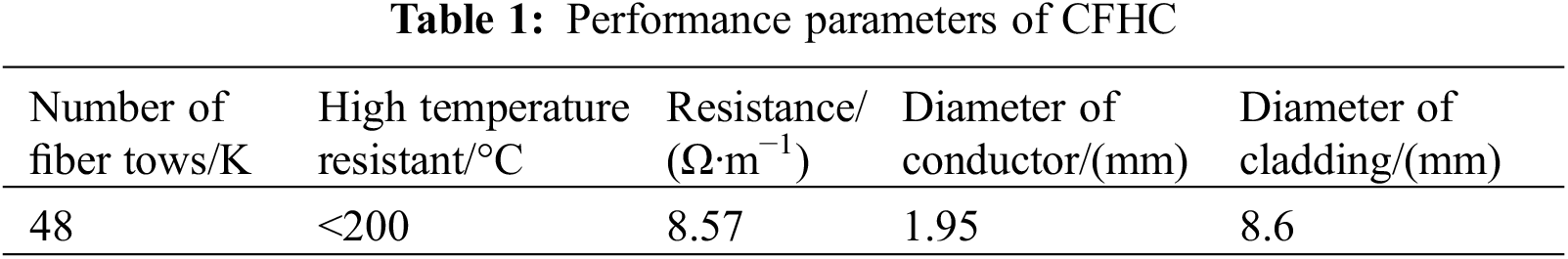
The CFHC is a reinforced plastic composite material made of carbon fiber wire bundles. Compared with other heating bodies such as cables, it has higher strength, fatigue resistance, high-temperature resistance, wear resistance, corrosion resistance, electrical and thermal conductivity, and many other excellent properties, which can meet the basic requirements of built-in materials in special environments such as concrete roads. The whole length of the finished carbon fiber yarn is 14 m, and the performance parameters are given in Table 1.
The finished product of the CFHC is shown in Fig. 1. The structure composition is shown in Fig. 2, which is carbon fiber bundles, Teflon, heat-resistant polyethylene, and stainless-steel woven mesh in order from inside to outside. Teflon has excellent heat resistance and low-temperature resistance. Teflon can work continuously at 260°C, has significant thermal stability, and it can work at −250°C without embrittlement. It also has very good insulation properties, making it an ideal coating for protecting carbon fiber bundles. Heat-resistant polyethylene is a monomer of ethylene and octene by metallocene-catalyzed copolymerization, and is non-toxic, odorless, and odorless. Its use temperature can be more than 80°C, processed into a pipeline after compression, corrosion resistance, life of up to 50 years, green, and recyclable. The outermost stainless steel woven wire mesh has a certain compressive, tensile, and shear strength, which can prevent the wear and tear of the CFHC caused by the friction resulting from the construction when the CFHC is pre-buried in concrete.
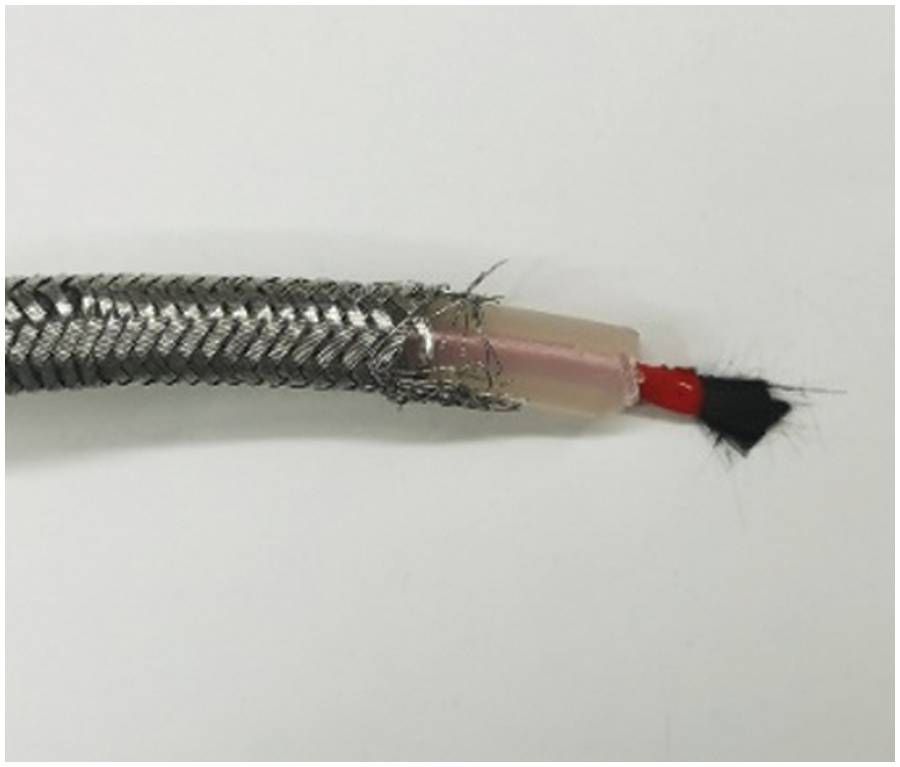
Figure 1: Finished product of CFHC
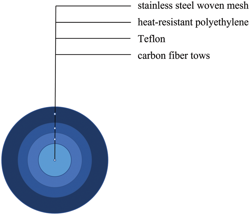
Figure 2: Structure diagram
2.2 Tensile and Compressive Test of Carbon Fiber Heating Cabl
The equipment used for the tensile test is a microcomputer-controlled electronic universal testing machine, as shown in Fig. 3. The displacement control mode was adopted during the tension, the loading strain rate was set to 0.001 s−1, and the speed was set to 20 mm/min. The fixture is chosen to be a flat chuck to avoid the resulting error caused by the sliding of the CFHC during the test. The tensile test selected 5 different lengths of the CFHC placed in the testing machine fixture midpoint line to ensure that the CFHC was straight and fixed. The test procedure follows the steps of adjust the distance between the two fixtures on the computer system to ensure that the initial force is 0 kN and record the distance between the two fixturesstart the tester and the CFHC starts to stretch until the cable breaks. The effective tensile length of the CFHC is 10 mm, and the test data that the tensile CFHC is disconnected from the middle of the CFHC rather than at the pinch is valid data.
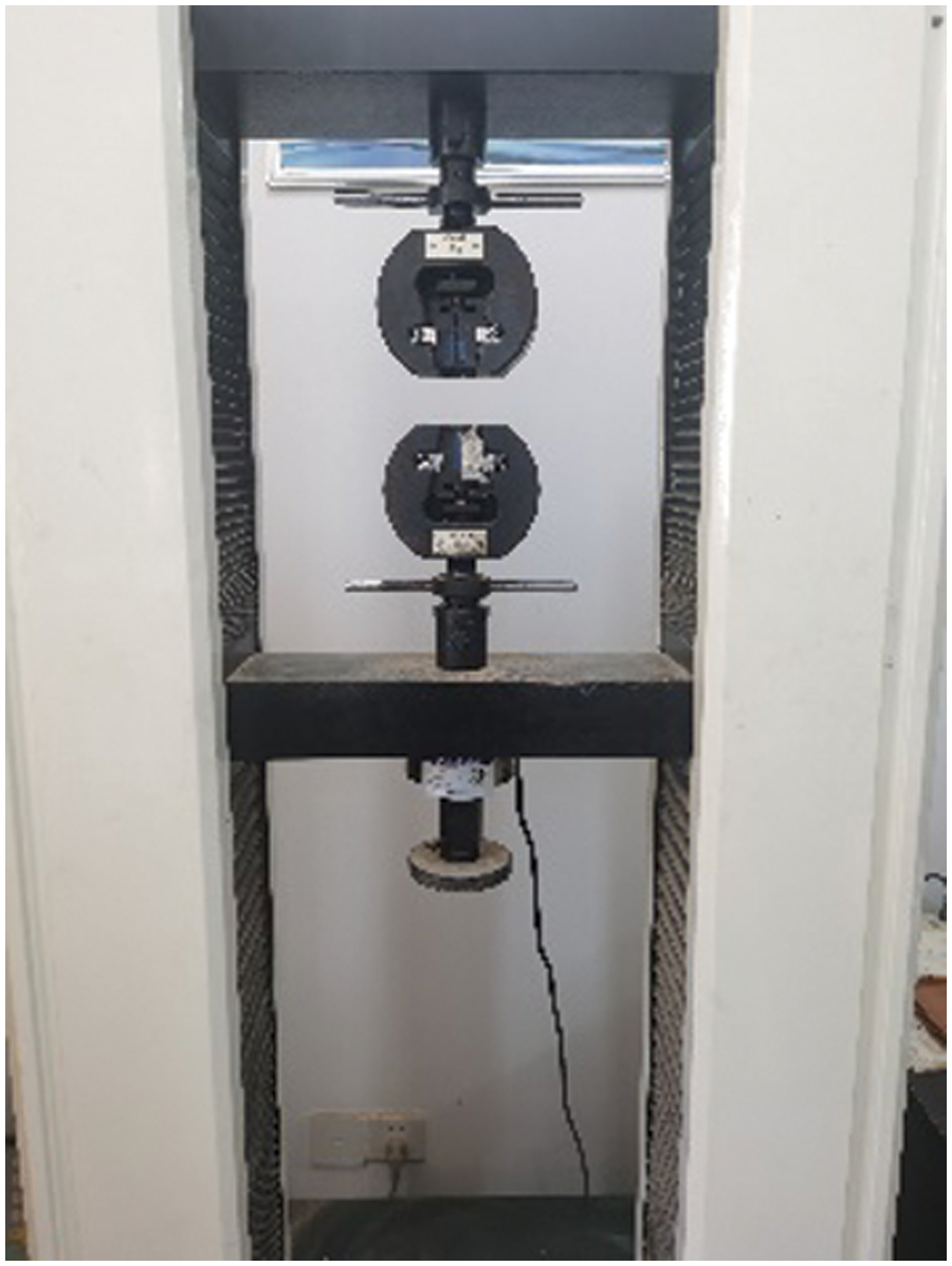
Figure 3: The microcomputer-controlled electronic universal testing machine
The equipment used in the compression tests is also a microcomputer control electronic universal testing machine. The displacement control mode was used for pressing, and the loading strain rate was set to 0.001 s−1, and the speed was set to 100 mm/min. Five CFHC of different lengths were selected and placed horizontally on the test machine, and the CFHC were fixed, with loading pads placed on each end of the CFHCs and the operational procedures carried out as follows the CFHC center should be aligned with the center of the lower plate of the testing machine; open the testing machine, when the upper-pressure plate is close to the CFHC, adjust the underlying plate, so that the contact balance is; the CFHC begins to deform until it fractures, recording the maximum compressive pressure of each CFHC; take the average of multiple sets of tests to avoid accidental errors.
Fig. 4 shows the failure morphology of the stretched CFHC. Obvious debonding occurs at the interface between the heat-resistant polyethylene and Teflon. The bonding of Teflon and carbon fiber bundles is relatively tight, which indicates that the carbon fiber bundles have good bonding ability with Teflon coating. The basic damage mode is Teflon matrix fracture and carbon fiber bundle axial fracture. This damage is caused by tensile damage of the coating and the interface between the coating or the coating and the carbon fiber strands. That is, some parts of the fracture surface are caused by the tensile damage of the coating, and another part is caused by the debonding of the adjacent interface.
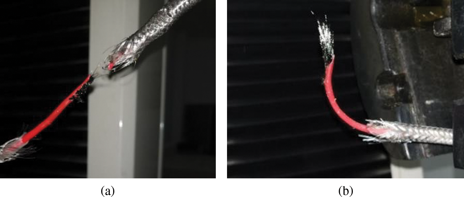
Figure 4: Fracture morphology of CFHC in the tensile test
The tension-deformation curve has two stress peaks, as shown in Fig. 5. The analysis suggests that this phenomenon is related to the bonding effect between the CFHC coating and the coating in the CFHC and between the coating and the carbon fiber bundle. Due to the injection molding process of CFHC, the adjacent media are not an ideal tight bond. This inevitably causes coupling of the CFHC between the coatings and the deformation of the carbon fiber bundle, which has an important effect on the overall mechanical properties of the CFHC. The bimodal phenomenon of the force-deformation curve of the CFHC may also be related to this, but further research is needed.
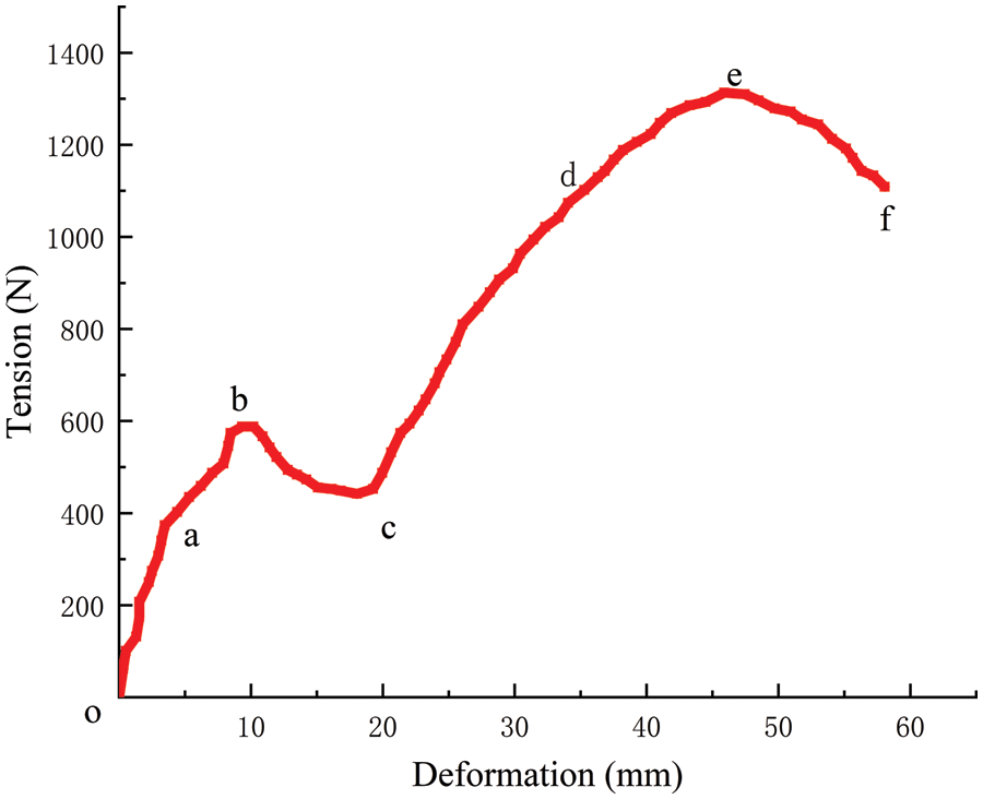
Figure 5: The obtained force-deformation curve
The o-a section in Fig. 5 is mainly when the outermost layer of the CFHC stainless steel compilation network by tension began to produce deformation, and belongs to the elastic deformation stage. From a macroscopic point of view, the tension and elongation share an approximately linear relationship, elastic elongation and the size of the force and the length of the CFHC is directly proportional to the CFHC cross-sectional area and is inversely proportional to the CFHC. The a-b section indicates that the stainless-steel mesh begins to slip as the applied tension gradually increases. The mesh pore increases, the heat-resistant polyethylene in the CFHC begins to bear the main force, and the deformation rate slows down. Section b-c indicates that when the force is applied to point b, the heat-resistant polyethylene suddenly produces plastic deformation, and the test force cannot be applied to the heat-resistant polyethylene completely and effectively. At this stage, the curve begins to show varying degrees of decrease in force, while plastic deformation increases sharply until it ends at point c.
When the CFHC is stretched in the vertical direction, the damage of the CFHC occurs at the coating interface of the adjacent coating due to the debonding damage between the coating and the coating, which reduces the bearing capacity. However, under continuous stretching, the rapid expansion of the fracture at the interface to the entire load-bearing area is hindered by the voids at the interlayer interface caused by injection molding. Thus, the Teflon-coated interface, which is tightly wrapped around the carbon fiber bundle, is not completely debonded, allowing the CFHC to continue to be stretched with a load-bearing capacity as evident in the c-d section. The Teflon coating breaks when the tensile force gradually increases. At this time, the carbon fiber bundle is mainly stressed, as evident in the d-e section.
Point e is the highest point of the force-deformation curve, and the tensile strength of the CFHC is calculated by the maximum stress corresponding to this point. The e-f segment indicates that the curve reaches the e point, the deformation at the carbon fiber bundle increases significantly, the effective cross-section decreases significantly, and the necking phenomenon occurs. After then, the axial deformation of the CFHC is mainly concentrated in the necking and the test reached point f, the CFHC completely broken.
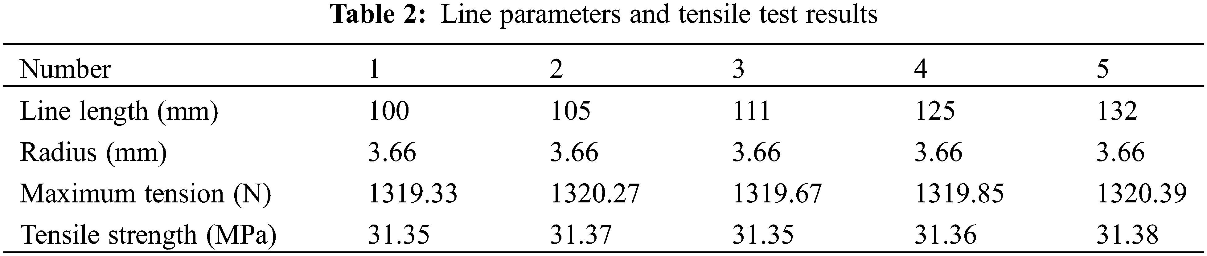
The tensile strength of the CFHC is calculated by the maximum stress corresponding to point e. The maximum stress corresponding to point e mainly comes from the bonding force between the carbon fiber bundle and the coating. The stronger the bonding force between the media, the greater the load it can withstand and the greater the overall tensile strength of the CFHC. The parameters and tensile test results of each wire section of the CFHC are presented in Table 2.
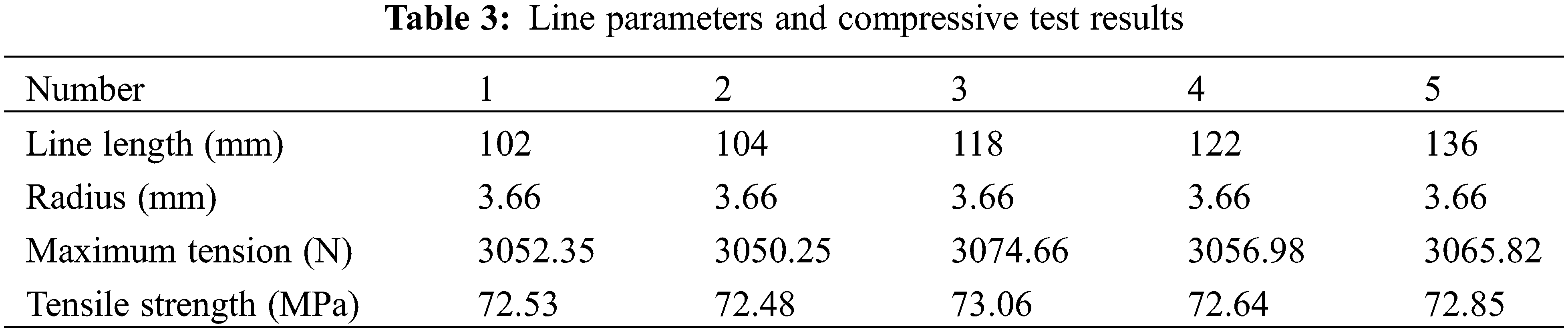
During the compression tests of the CFHC, there is great friction between the upper and lower ends and the indenter, which hinders the lateral deformation of the upper and lower ends of the CFHC, so the CFHC is drum-shaped after compression. During the compression process of the CFHC, the outermost stainless steel woven mesh cracks first, as shown in Fig. 6. With continued pressure, the CFHC will get flatter and flatter, but the appearance of a heat-resistant polyethylene layer is not always destroyed. The change in resistance of the CFHC is measured by a voltmeter to prove whether the carbon fiber bundle inside the CFHC is damaged. The maximum compressive strength is calculated by taking the maximum pressure that the CFHC can withstand when the resistance changes. The parameters and compressive test results of each wire section of the CFHC are shown in Table 3.
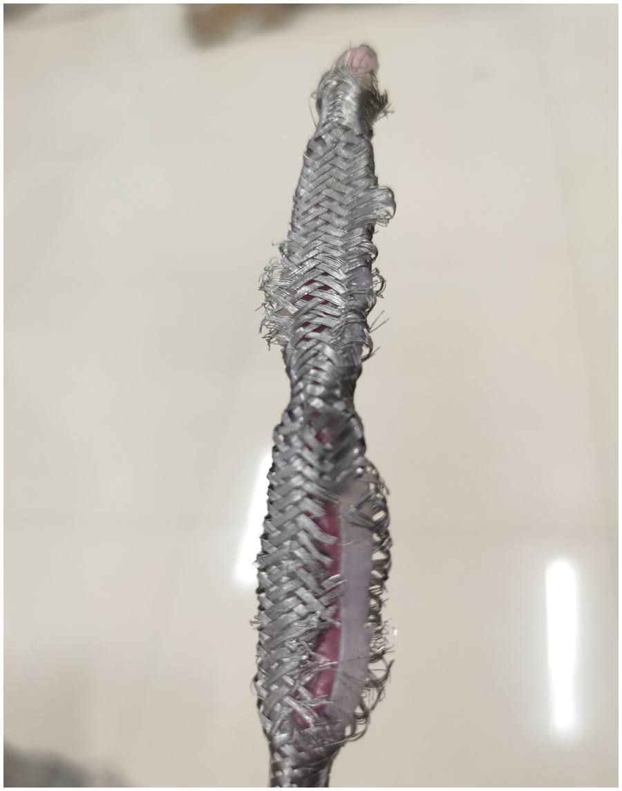
Figure 6: The compression failure mode of the CFHC
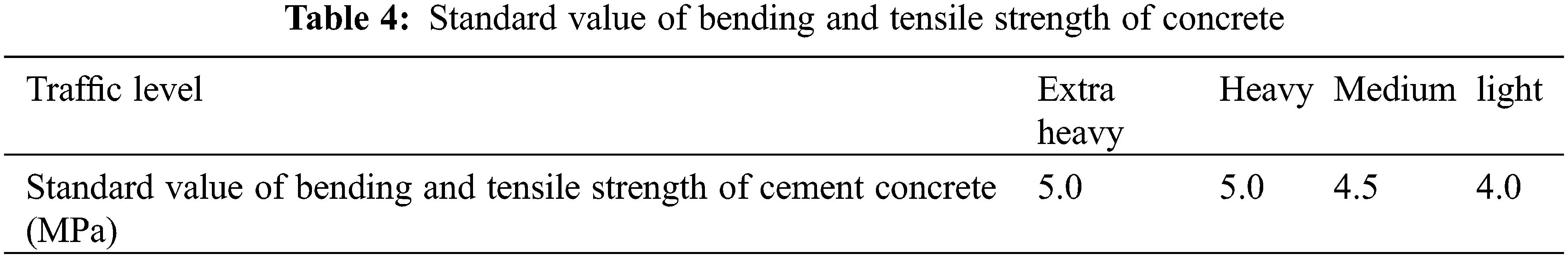
The strength design of cement concrete in the JTG D40-2011 “Design Specification for Highway Cement Concrete Pavement” [20] is controlled by the strength of 28 d age bending period. The design bending and tensile strengths from the specification are 4.0 MPa for light traffic load classes, 4.5 MPa for medium classes, and 5.0 MPa for heavy, extra heavy and very heavy classes, as given in Table 4.
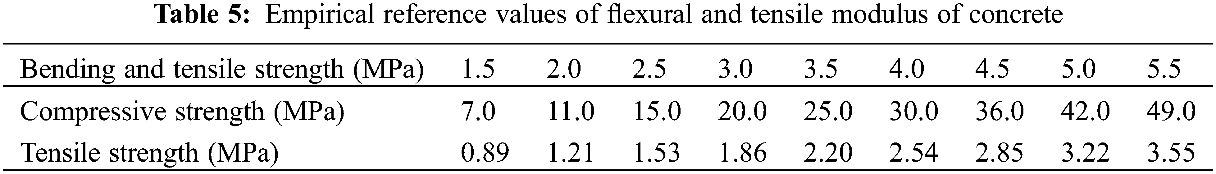
Taking the traffic grade extra heavy as an example, the bending and tensile strength of cement concrete with an empirical reference value of bending and tensile modulus is 5.0 MPa, corresponding to a tensile strength of 3.22 MPa and a compressive strength of 42 MPa, as given in Table 5. By the CFHC tensile and compressive strength test results, it can be considered to ensure that the normal operation of the CFHC is not damaged by the maximum tensile strength value of about 31 MPa, the maximum compressive strength value of about 72 MPa. It is therefore reasonable to conclude that the compressive strength and tensile strength of CFHC is greater than the design strength of concrete pavement, and it can work normally when buried in concrete pavement.
2.3 The Cold and Heat Cycle Strength Tests of the CFHC
The equipment used is a high and low-temperature alternating road mechanics test chamber, as shown in Fig. 7. The CFHC, K-type thermocouple wire, Keysight-34972A data acquisition instrument, and the schematic diagram of the cold and heat cycle test system are shown in Fig. 8. The test is divided into two steps. Firstly, the CFHC is subjected to cold and heat cycle treatment at different temperatures, and then the treated sample is subjected to tensile and compressive tests which are divided into 7 groups according to the temperature (−20°C–40°C) and 5 groups according to the number of cycles (10–50 times). Each group of tests consisted of three samples, a total of 105 CFHCs with a length of 2 m.
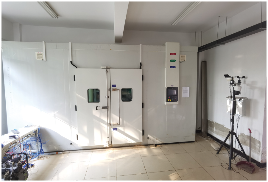
Figure 7: The high and low-temperature alternating road mechanics laboratory
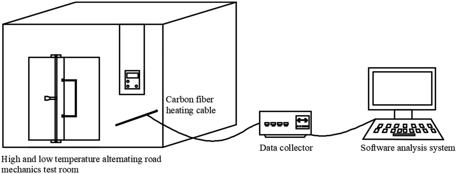
Figure 8: The cold and hot cycle test system
Taking the ambient temperature of −20°C as an example, the test steps are described in detail:
(1) The grouped 15 CFHCs were placed in a freezer with an ambient temperature of −20°C. The k-type thermocouple lines were arranged on the CFHC to measure the surface temperature of the CFHC in real time. The CFHC is connected to the power supply and energized for heating. The surface of the CFHC reaches 60°C (the actual engineering CFHC reaches the highest temperature of about 60°C, as the highest temperature of the CFHC hot and cold cycle), continue to power heating for 1 h to ensure that the CFHC is uniformly heated inside.
(2) Disconnect the power supply and the CFHC stops heating. The CFHC surface is cooled to the freezing ambient temperature, cooled for 1 h, and then heated again to 60°C and continued for 1 h then disconnected and cooled to ambient temperature.
(3) Repeat Step 2 for 10 cycles. At the 10th cooling to ambient temperature and keep for 1 h, take out the CFHC labeled paper labelled-20-10-X (ambient temperature −20°C, cycle 10 times, X represents the CFHC number, take 1,2,3).
(4) Repeat the above steps, so that the CFHC at −20°C–40°C was experienced 10, 20, 30, 40, 50 times of thermal cycle treatment.
(5) After the completion of the hot and cold cycle at different temperatures, the tensile and compressive tests were carried out on all CFHCs. Refer to 2.2 for the test procedure, and test the strength change of the CFHC after hot and cold cycles at different temperatures.
The results of the tensile and compressive tests of the CFHC after hot and cold cycles at different temperatures are presented in Table 6. The variation of tensile and compressive strengths of the CFHC with temperature and number of rings was obtained according to Table 6 as shown in Fig. 9. The tensile strength and compressive strength of the CFHC decreased with the increase of the number of cycles. Taking the ambient temperature of −20°C as an example, the tensile strength of the CFHC decreases from 31.5 to 31.3 MPa after 10 times of hot and cold cycles compared with 50 times. The compressive strength decreased from 73.2 to 72.8 MPa. In the same number of hot and cold cycles, the strength of the CFHC decreases with the increase in temperature. Taking the number of cycles as 10, for example, the ambient temperature increases from −20°C to 40°C, the tensile strength of the CFHC decreases from 31.5 to 31.1 MPa; the compressive strength of the CFHC decreases from 73.2 to 72.4 MPa.
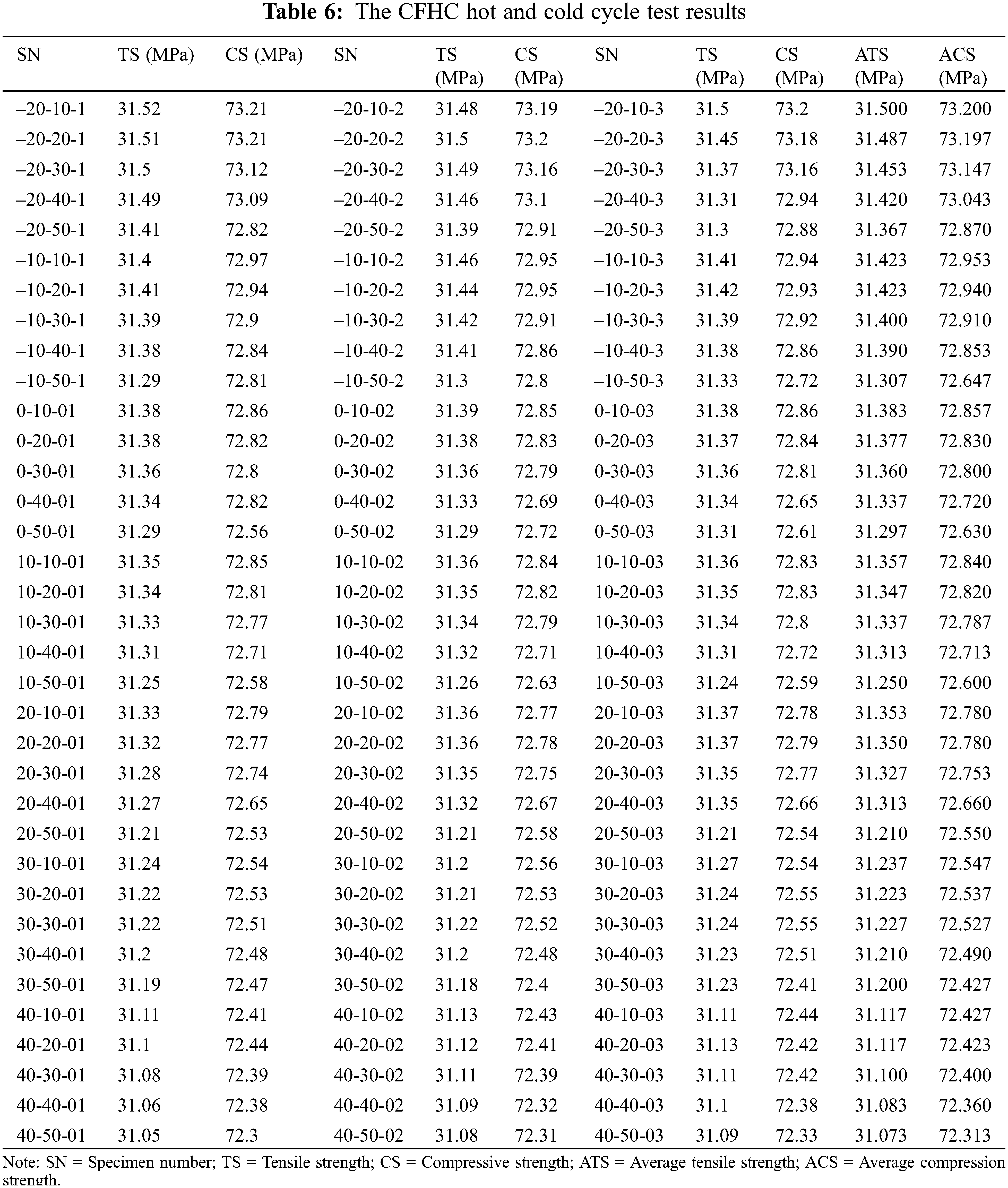
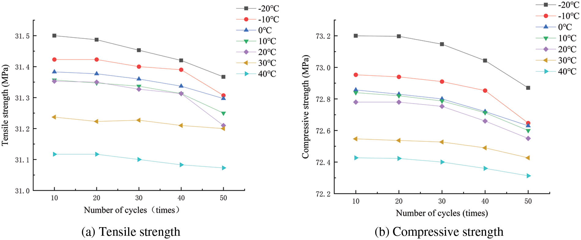
Figure 9: Mechanical properties of CFHC under different temperature cycles
When the CFHC is in the low-temperature stage (−20°C to +20°C), the same temperature effect of the CFHC strength with the number of hot and cold cycles to increase the decline is faster. From −20°C to 20°C, the tensile strength of the CFHC decreases with the increase of the number of hot and cold cycles, and the decrease is 0.42%, 0.36%, 0.27%, 0.34%, and 0.46%, respectively. The compressive strength decreased by 0.45%, 0.42%, 0.31%, 0.33%, and 0.32%, respectively. When in the high-temperature stage (30°C to 40°C), the tensile strength of the CFHC decreases with the increase of the number of cold and hot cycles, and the decrease is 0.11% and 0.14%, respectively. The compressive strength of the CFHC decreased by 0.17% and 0.16%, respectively. When the CFHC is in the high temperature stage (from 30°C to 40°C), its tensile strength and compressive strength decrease at a significantly slower rate. In the high-temperature stage, the actual heating temperature difference of the CFHC is only 20°C to 30°C, the temperature difference is relatively small to the strength of the CFHC, and the impact of the hot and cold cycle on the strength of the CFHC is relatively small.
As the tensile strength and compressive strength of the CFHC decreased with the increase of temperature and the number of cycles, it shows that the temperature and the number of hot and cold cycles played a certain weakening effect on the strength of the CFHC, but the decrease of the strength of the CFHC was not more than 0.5%, which can still meet the good operation of the CFHC in the snow and ice melting system of the concrete pavement in the long term.
3 Influence of CFHC on Pavement Strength
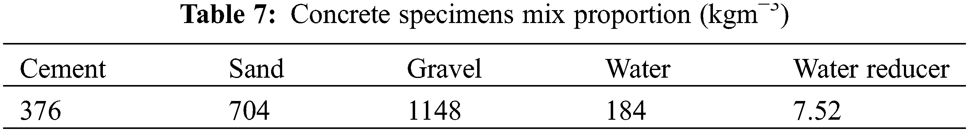
C30 concrete specimens were made according to the JTG D40-2011 “Design Specification for Highway Cement Concrete Pavement” [20] and the JTG/T F30-2014 “Technical Rules for Construction of Highway Cement Concrete Pavement” [21]. The mix proportion is given in Table 7. The cement used for making concrete specimens was PO 42.5 ordinary silicate cement. The coarse aggregates were selected from 5 to 30 mm particle sizes. Natural river sand with a fineness modulus of 2.75 was selected for the fine aggregate. The water reducer adopts a slow-setting water-reducing agent, and the water reduction rate reaches 20%.
The test was carried out in 2 steps. Firstly, the specimens were fabricated and maintained, and then the treated specimens were subjected to a compressive strength test and splitting tensile strength test.
(1) The production of concrete specimens with pre-buried CFHCs: the concrete fabrication process is shown in Fig. 10. The size of the mold is 100 mm × 100 mm × 100 mm, and the 100 mm CFHC is placed in the middle of the mold level. The test ages of concrete specimens include 3, 7, 28, and 60 d. Each age with or without embedded CFHC is a group of specimens, a total of 48 concrete specimens.
(2) The concrete specimens with embedded CFHCs and the specimens without embedded CFHCs were tested for compressive strength and splitting tensile strength. The test equipment is a microcomputer servo pressure testing machine. The mechanical properties of the specimens were tested and calculated according to the provisions in the GB/T 500812019 “Standard for Physical and Mechanical Properties of Concrete Test Methods” [22]. The specimen compressive strength size conversion factor is 0.95 and the splitting tensile strength conversion factor is 0.85.
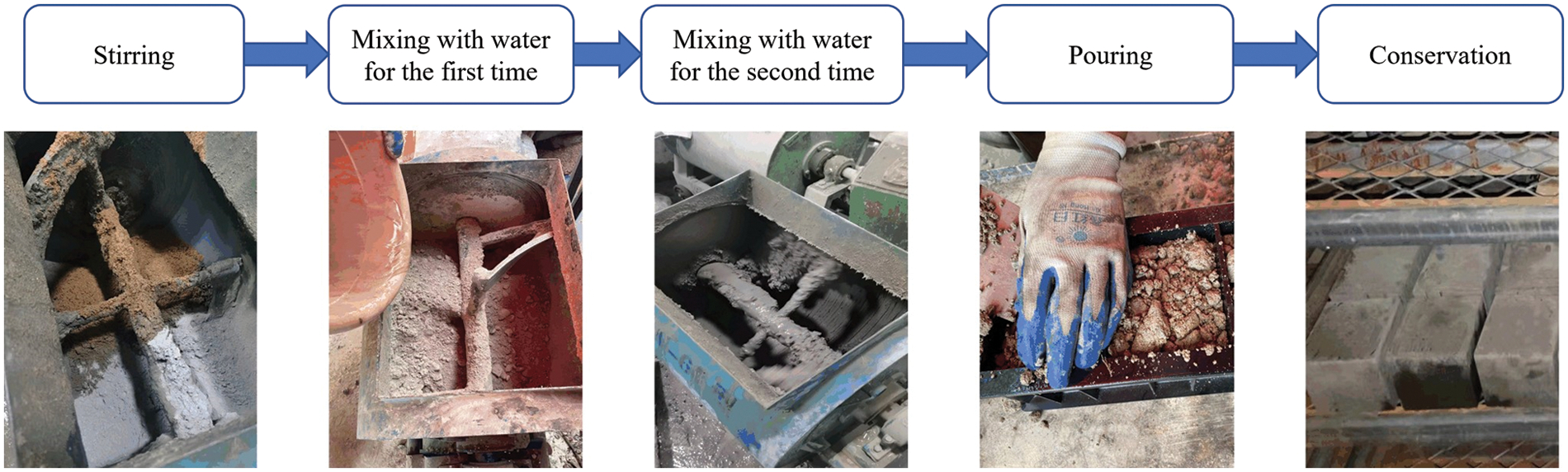
Figure 10: Concrete production process
Compression test: Place the specimen on the press plate of the pressure tester and align the center of the specimen with the center of the press plate of the tester. Turn on the tester and start adding load continuously and evenly, the loading speed is taken as 0.5 MPa per second. The specimen began to deform sharply until the failure, and the failure load was recorded, as shown in Fig. 11. Take the average of the measured values of a group of 3 specimens as the compressive strength value of the group of specimens.
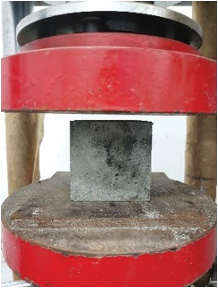
Figure 11: Compression test
Splitting tensile test: Place the specimen on the lower plate of the pressure tester. The center of the specimen is aligned with the center of the lower plate of the test machine, and the cushion pad is placed. The cushion pad is aligned with the center line above and below the specimen. Turn on the tester and start adding load continuously and evenly, the loading speed is taken as 0.05 MPa per second. The specimen began to deform sharply until the failure, and the failure load was recorded, as shown in Fig. 12. Take the average of the measured values of a group of 3 specimens as the splitting tensile strength value of the group of specimens.
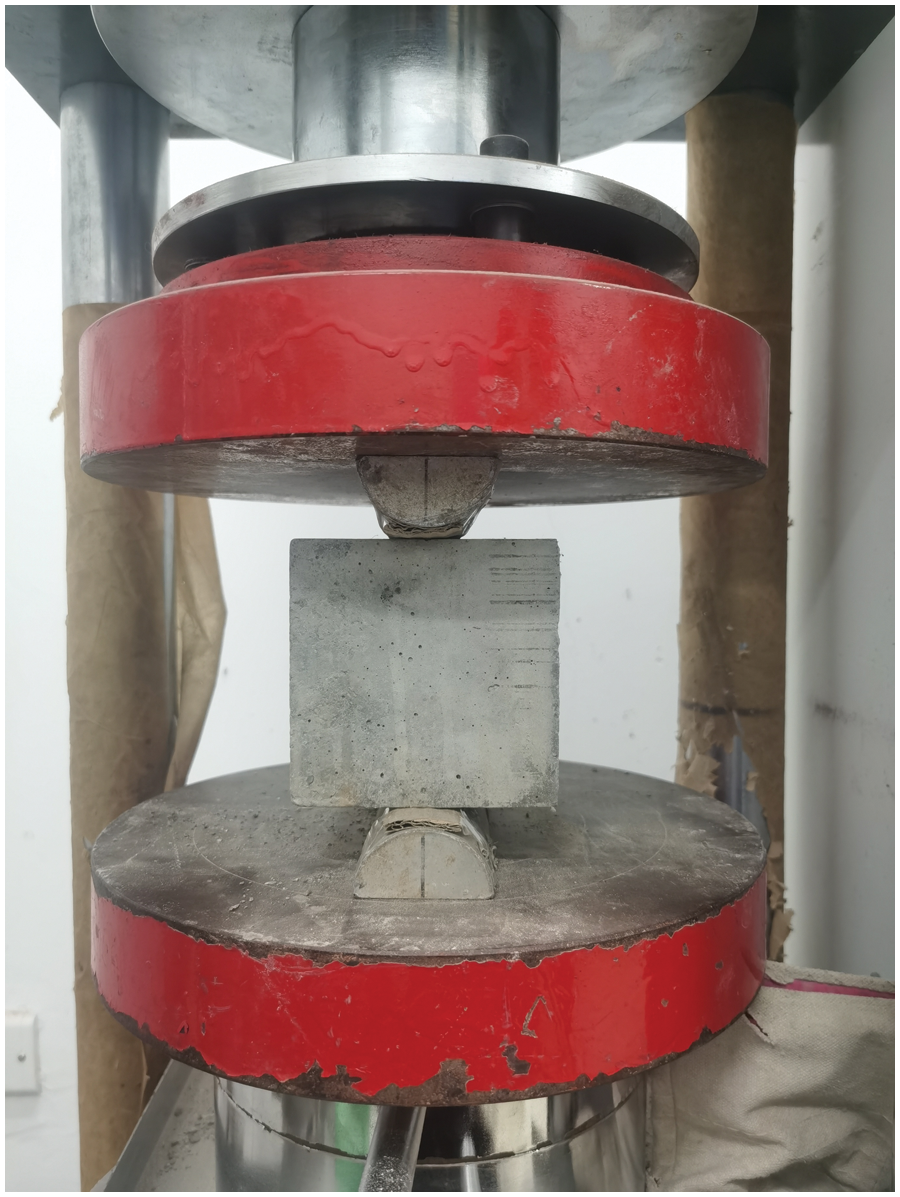
Figure 12: Splitting tensile test
The damage pattern is shown in Fig. 13, selected from a CFHC buried at a depth of 2 cm and a concrete specimen with a curing age of 28 d. The influence of different factors on the compressive strength of concrete specimens is shown in Fig. 14.
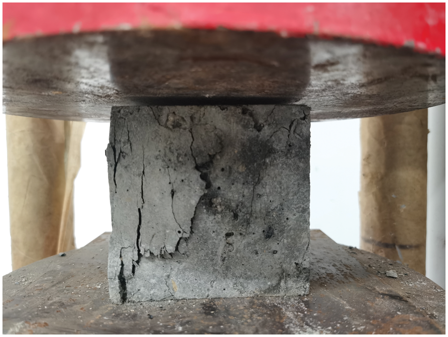
Figure 13: Specimen compressive damage pattern
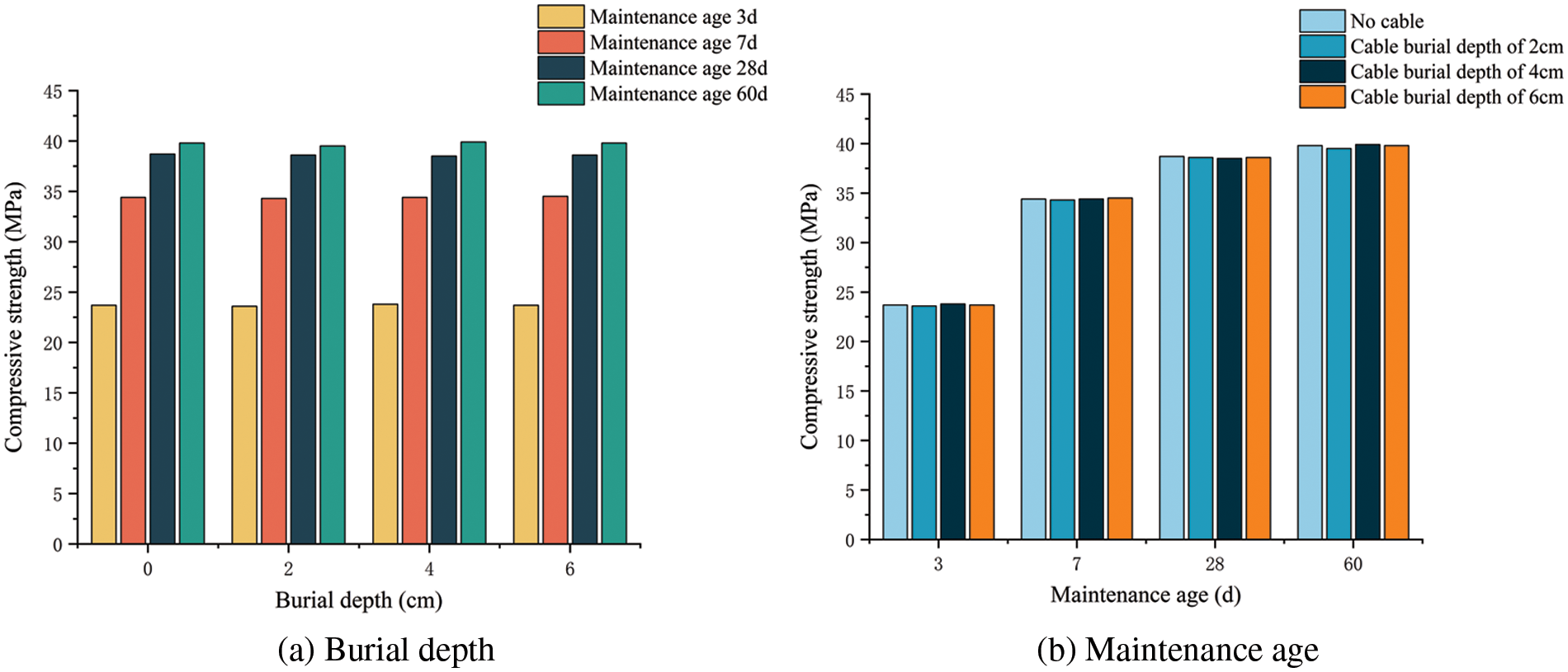
Figure 14: Influence of different factors on compressive strength of concrete specimens
From the compressive damage pattern, the damage pattern of the pre-built CFHC concrete specimens with the same curing age is basically the same as that of the reference concrete specimens. The specimens were loaded with many cracks on the surface, but the cracks did not come off and still had good integrity. At the same age, the compressive damage patterns of concrete specimens with pre-buried CFHC of different burial depths were basically the same, and there was no significant difference with the concrete specimens of the blank control group.
As shown in Fig. 14, the compressive strength of concrete specimens with CFHC pre-buried at different burial depths is basically the same, and the burial depth does not affect the compressive strength of the pavement. From Fig. 14b, the compressive strength of concrete specimens with pre-buried CFHC of different burial depths for each group under the same curing age is basically the same with no significant difference. The early compressive strength of all four groups of specimens increased rapidly, and the compressive strength values of the specimens reached 61.14%–61.82% of the compressive strength values at 28 d after 3 d of curing. It reached 88.86%–89.38% of the compressive strength value at 28 d of maintenance and 7 d of maintenance. This reflects the characteristics of fast hardening and early strengthening of concrete and shows that the pre-burial of CFHC does not affect the growth of compressive strength of pavement concrete at early ages.
3.2 Splitting Tensile Test Results
In the splitting tensile test on concrete specimens, it was found that the duration of the splitting tensile damage process in each group of specimens increased gradually with the growth of the curing age, but the final damage pattern of each specimen in the group did not differ significantly. Taking the curing age of 28 d as an example, the concrete specimens with and without pre-buried CFHC showed slight cracks in the middle of the specimens after loading. As the load gradually increases, the crack extends to both ends of the specimen and gradually evolves into a vertical crack. The specimen is close to damaging before the rapid development of cracks and eventually shows the effect of vertical cracks running through the specimen, splitting it in two. The fracture is accompanied by a large ringing sound, and the whole process of damage to the specimen occurs in a short time, showing obvious brittle damage characteristics. The splitting tensile damage pattern is shown in Fig. 15. The splitting tensile damage patterns of concrete specimens with CFHC pre-buried at different burial depths were basically the same at the same age, and there was no significant difference with the concrete specimens of the blank control group.
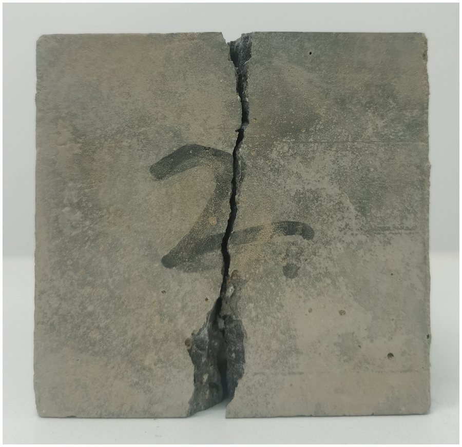
Figure 15: Specimen showing splitting tensile damage pattern
The pre-buried CFHC can be clearly seen in the split tensile damaged concrete specimens, as shown in Fig. 16. Insert the pen of the multimeter into both ends of the CFHC, and use the ohm class to measure the resistance of the CFHC. Adjust the tap position to the minimum range. The values on the multimeter are the same as those measured before the test block breaks the CFHC. The resistance of the CFHC remains unchanged before and after the concrete test block is destroyed, so it can be shown that the CFHC is still intact and can operate normally after the concrete test block is destroyed.
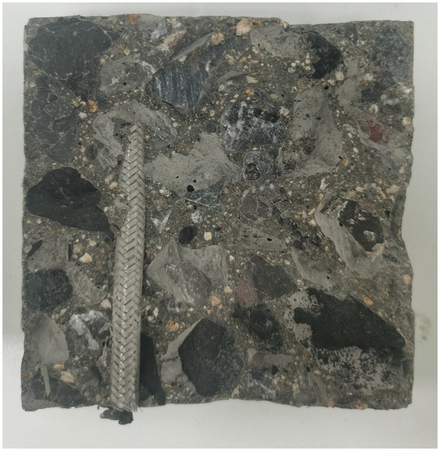
Figure 16: Pre-buried CFHC pattern
The influence of different factors on the splitting tensile strength of concrete specimens is shown in Fig. 17. The splitting tensile strength of concrete specimens with pre-buried CFHC of different burial depths is basically the same, and the burial depth does not affect the tensile strength of the pavement. The tensile strength of concrete specimens with CFHC embedded in different depths under the same curing age is basically the same, and there is no significant difference. The splitting tensile strength of all groups of specimens increased with the age. The splitting tensile strength values of the concrete specimens at age 3 d reached 51.35% to 51.43% of the splitting tensile strength values at age 28 d. When the age is 7 d, it reaches 64.86%–65.71% of the 28 d splitting tensile strength value. As the splitting tensile strength of concrete increases with time, the strength of the first 7 d increases rapidly, which can reach more than 60% of the 28 d strength value. It is also shown that the pre-burial of CFHC does not affect the growth of splitting tensile strength of pavement concrete at early ages.
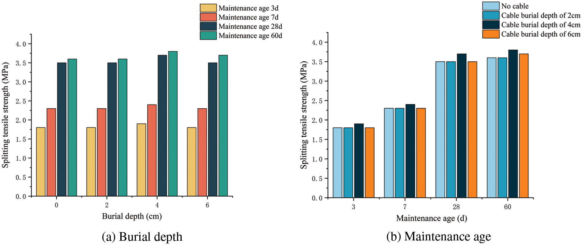
Figure 17: Influence of different factors on splitting tensile strength of concrete specimens
4 Finite Element Simulation of Mechanical Properties of Carbon Fiber Heating Cable
To further verify the mechanical properties of the CFHC in the concrete pavement in the test, and to explore the feasibility of applying the simulation results to the actual project, the concrete specimen model with the pre-buried CFHC is established for static loading test using ANSYS finite element software.
4.1 Basic Theory of Elastic Space
Let the elastomer strain be
From the geometric aspect, the equation for the relationship between deformation and displacement in a right-angle coordinate system can be expressed as
From the physical aspect, the relationship between the elastomer deformation and stress in the right-angle coordinate system as
In the construction of pavement ice and snow melting project, heating materials are often buried by slotting on concrete pavement structure. The groove is carved after the middle surface of the pavement is formed. The CFHC is fixed in the groove, and then the upper layer is paved and rolled. The best snow and ice melting effect was achieved when the CFHC was buried at a depth of 4 cm [8]. Therefore, the static structure module was selected in ANSYS finite element software to build two concrete specimen models with 100 mm cubes in length, width, and height. The 48K-type CFHC with a length of 140 mm was selected to be buried in the horizontal center of one concrete specimen with a burial depth of 40 mm. Due to the good bonding performance between CFHC and concrete after the completion of construction, there is no slippage between them. Therefore, the modeling is set as the embedded relationship between the two, and the outer surface of the CFHC is manually set as the contact surface. In the model, the lower surface of the concrete specimen is restrained by a fixed end, and a static load of 400 kN is applied to the upper surface of the two concrete specimens. Specific material parameters are shown in Table 8. The model mesh is shown in Fig. 18.
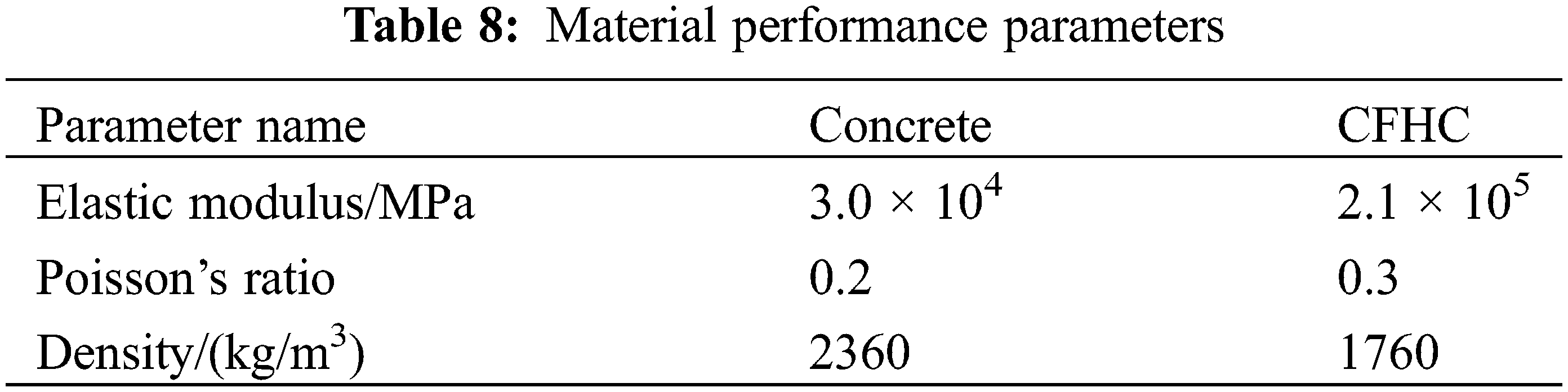
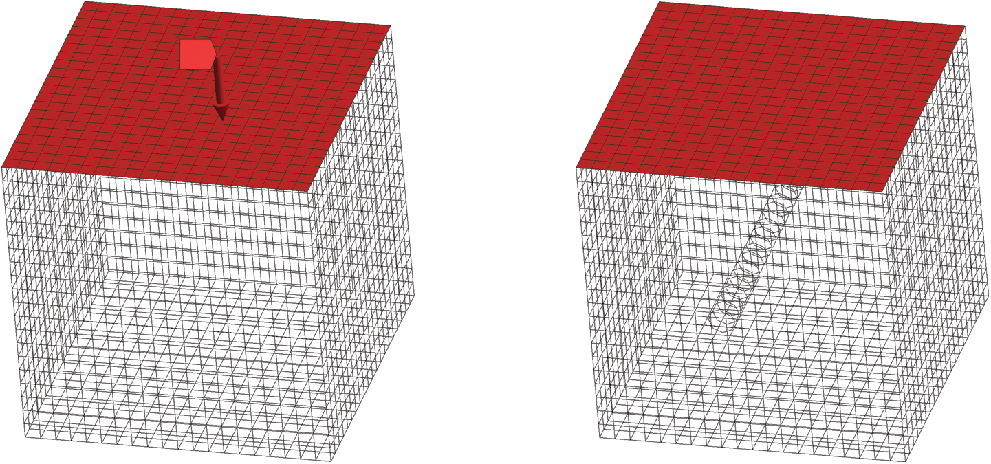
Figure 18: Model meshing
For the force simulation of the model based on compressive tests of concrete specimens with pre-buried CFHC. Fig. 19 shows the deformation results of the plain concrete specimen and the concrete specimen with pre-buried carbon fiber heating cable. Fig. 20 shows the equivalent stress results for the plain concrete specimen and the concrete specimen with pre-buried CFHC.
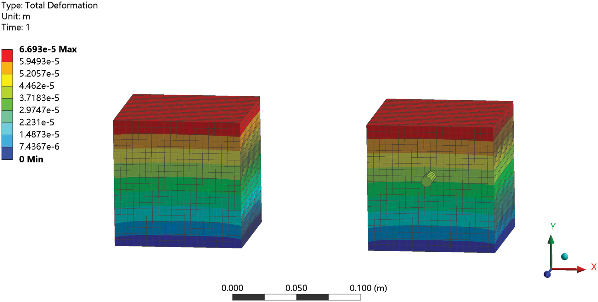
Figure 19: Specimen deformation
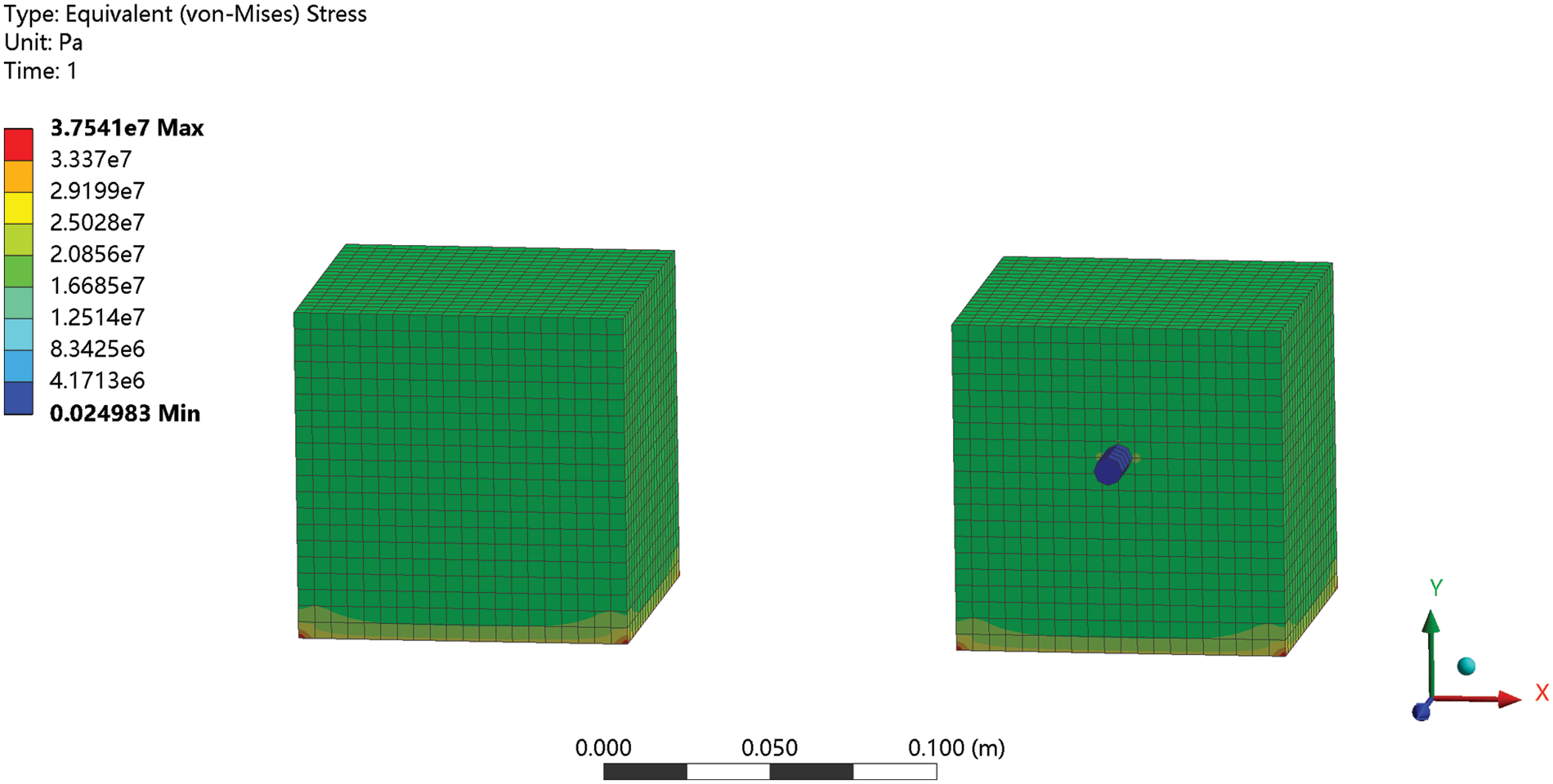
Figure 20: Equivalent stress of specimen
From Fig. 19, the deformation results of concrete specimens with pre-buried CFHC and plain concrete specimens are basically the same, and there is no obvious deformation at the place where the CFHC is buried. From Fig. 20, the equivalent stress results of concrete specimens with pre-buried CFHC and plain concrete specimens are basically the same, and there is no stress concentration in the buried CFHC.
Fig. 21 shows the deformation results of the CFHC. Fig. 22 shows the equivalent stress results of the CFHC. From Fig. 21, the deformation of both sides of the CFHC exposed outside the concrete specimen is larger compared to the deformation of the buried inside the concrete specimen. The minimum deformation of the CFHC occurs at the center of the buried test piece part, 3.9567 × 10⁻² mm, and the maximum deformation occurs at the part of the CFHC exposed outside the test piece, 3.9372 × 10⁻² mm. Due to the good adhesion between the embedded part of the CFHC and the concrete specimen, when the upper part of the concrete specimen is uniformly stressed, the embedded part of the CFHC will not slip. The exposed part of the CFHC will produce slight deformation, and the overall result of deformation is small and negligible, which is in line with the actual test situation.
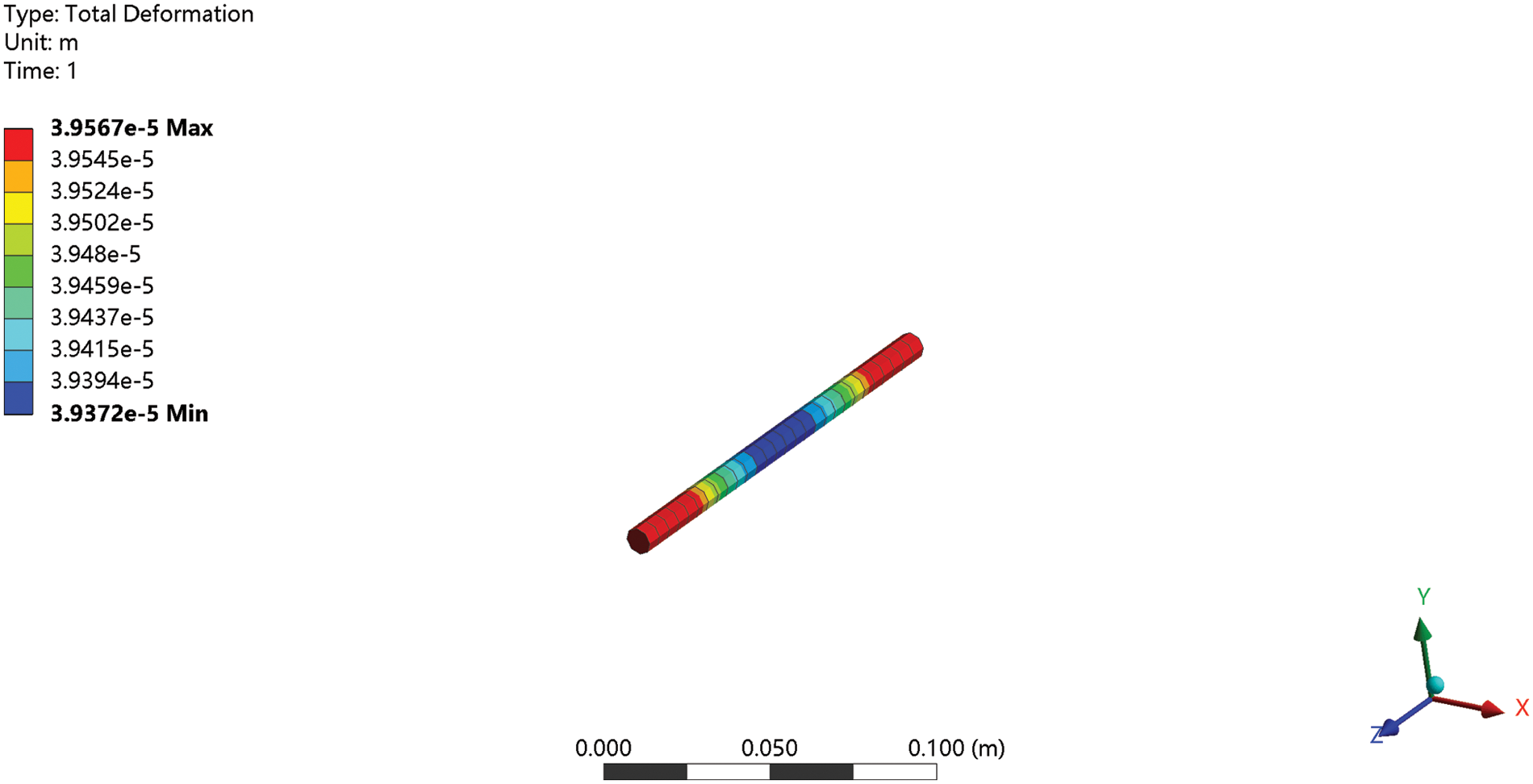
Figure 21: Deformation of the CFHC
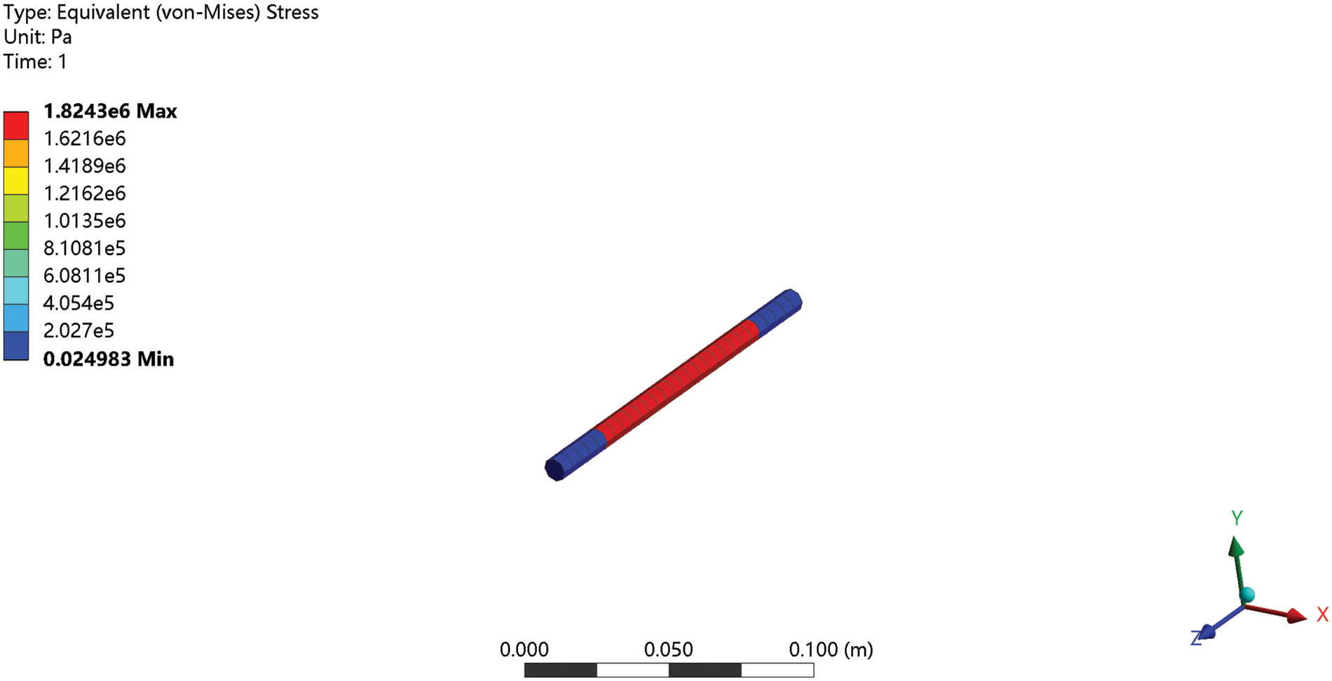
Figure 22: Equivalent stress of the CFHC
From Fig. 22, the internal force of the CFHC embedded in the concrete specimen is uniform, and the equivalent stress is 1.8243 MPa. The equivalent stress of the exposed part of the specimen is small, which is 2.4983 × 10⁻⁸ MPa. The maximum compressive strength of the cable is 72 MPa, which is much larger than the equivalent stress strength of the CFHC when the concrete specimen is compressed. The CFHC will not be damaged, which is in line with the actual test.
The test shows that the results obtained by numerical simulation are in line with the actual law. The CFHC is uniformly stressed in the concrete, and the deformation is very small and negligible. Through the mutual verification of the simulation test results and the test results, it is concluded that the pre-burial of the CFHC will not affect the strength of the concrete, and the CFHC will not be damaged when buried in the concrete.
In this paper, the mechanical properties of the CFHC and its influence on the strength of pavement were systematically investigated with CFHC as the research object. The change law of tensile and compressive strength of CFHC working at different temperatures and the change law of tensile and compressive strength of concrete specimens with pre-buried CFHC were analyzed, and the following conclusions were obtained:
(1) The maximum tensile strength of the CFHC is about 31 MPa, and the maximum compressive strength is about 72 MPa. The strength of CFHC far surpasses the design strength of concrete pavement, and it can work normally without being damaged by the pavement load when buried in the concrete pavement.
(2) Under the action of the thermal cycle, the strength of the CFHC will decrease with the increase of temperature and cycle times, and the reduction range is very small, which can still allow for the effective operation of the CFHC in road snow and ice melting system for a long time.
(3) The different burial depths of the CFHC do not affect the strength of concrete pavements, and the pre-burial of CFHC does not affect the growth of concrete strength at early ages. The results of the study provide a reference for the use of CFHC for snow and ice melting to improve the safety of winter traffic.
Funding Statement: The authors have received financial support from the National Natural Science Foundation of China (No. 52078194), the Key Research and Development Program of Hubei Province (No. 2021BGD015), and the Knowledge Innovation Project of Wuhan (No. 2022010801010259).
Conflicts of Interest: The authors declare that they have no conflicts of interest to report regarding the present study.
References
1. Hintz, W. D., Relyea, R. A. (2017). Impacts of road deicing salts on the early-life growth and development of a stream salmonid: Salt type matters. Environmental Pollution, 223, 409–415. [Google Scholar] [PubMed]
2. Malakooti, A., Theh, W. S., Sadati, S., Ceylan, H., Kim, S. et al. (2020). Design and full-scale implementation of the largest operational electrically conductive concrete heated pavement system. Construction and Building Materials, 255, 119229. [Google Scholar]
3. Cheng, Y., Zhou, Q., Liu, Y., Li, X., Feng, X. (2021). Preparation and performance study of carbon fiber grounded conductive concrete based on vibration mixing technology. Concrete and Cement Products, (2), 61–64+100. [Google Scholar]
4. Li, M., Min, Q., Zhang, M., Liu, D., Feng, D. (2021). Mechanical property tests and fine simulation analysis of new crushed conductive concrete functional materials. Scientia Sinica Technologica, 52(8), 1245–1258. [Google Scholar]
5. Dehghanpour, H., Yilmaz, K., Ipek, M. (2019). Evaluation of recycled nano carbon black and waste erosion wires in electrically conductive concretes. Construction and Building Materials, 221, 109–121. [Google Scholar]
6. Adari, S. K., Urmila, P., Bharathi, K. P. (2022). Thermal properties of conductive concrete using graphite powder and steel fibers. Journal of Building Pathology and Rehabilitation, 8(1), 9. [Google Scholar]
7. Dehghanpour, H., Yilmaz, K., İpek, M. (2019). Evaluation of recycled nano carbon black and waste erosion wires in electrically conductive concretes. Construction and Building Materials, 221, 109–121. [Google Scholar]
8. Yuan, Y., Zhang, Y., Guo, B. (2019). Experimental study on snow melting of asphalt concrete with pre-buried carbon fiber heating lines. Chinese Science and Technology Paper, 14(6), 5. [Google Scholar]
9. Habibzadeh-Bigdarvish, O., Yu, X., Li, T., Lei, G., Banerjee, A. et al. (2021). A novel full-scale external geothermal heating system for bridge deck de-icing. Applied Thermal Engineering, 185, 116365. [Google Scholar]
10. Mohammed, A. G., Ozgur, G., Sevkat, E. (2019). Electrical resistance heating for deicing and snow melting applications: Experimental study. Cold Regions Science and Technology, 160, 128–138. [Google Scholar]
11. Daniels, J. W., Heymsfield, E., Kuss, M. (2019). Hydronic heated pavement system performance using a solar water heating system with heat pipe evacuated tube solar collectors. Solar Energy, 179, 343–351. [Google Scholar]
12. Mirzanamadi, R., Hagentoft, C. E., Johansson, P., Johnsson, J. (2018). Anti-icing of road surfaces using hydronic heating pavement with low temperature. Cold Regions Science and Technology, 145, 106–118. [Google Scholar]
13. Zhao, H., Wu, Z., Wang, S., Zheng, J., Che, G. (2011). Concrete pavement deicing with carbon fiber heating wires. Cold Regions Science and Technology, 65, 413–420. [Google Scholar]
14. Zhao, H., Wang, S., Wu, Z., Che, G. (2010). Concrete slab installed with carbon fiber heating wire for bridge deck deicing. Journal of Transportation Engineering, 136, 500–509. [Google Scholar]
15. Ke, L., Jian, L., Xing, H., Yong, Y. (2021). Finite element analysis of snow and ice melting pavement based on carbon fiber heating cables. Science and Technology Information, 19(19), 4. [Google Scholar]
16. Kim, H., Ban, H., Park, W. (2020). Deicing concrete pavements and roads with carbon nanotubes (CNTs) as heating elements. Materials, 13(11), 2504. [Google Scholar] [PubMed]
17. Qian, Z., Yan, Z., Zhi, W. (2015). Research on snow and ice melting with carbon fiber heating lines for concrete pavements. Highway and Transportation Technology, 32(2), 41–48. [Google Scholar]
18. Huang, C., Yu, H., Tan, Y., You, W. (2021). Experimental and numerical simulation of snow and ice melting by carbon fiber electrothermal method on airport roads. Journal of Civil Engineering and Management, 38(2), 119–125+144. [Google Scholar]
19. Yang, Z., Zhan, X., Zhou, X., Xiao, H., Pei, Y. (2021). The icing distribution characteristics research of tower cross beam of long-span bridge by numerical simulation. Energies, 14(17), 5584. [Google Scholar]
20. Ministry of Transport of the People’s Republic of China. (2011). Specification for design of cement concrete pavement for highways. China: People’s Traffic Press. [Google Scholar]
21. Ministry of Transport of the People’s Republic of China. (2014). Technical details of road cement concrete pavement construction. People’s Traffic Press. [Google Scholar]
22. Ministry of Housing and Urban-Rural Development of the People’s Republic of China. (2019). Standard for test methods for physical and mechanical properties of concrete. China: China Construction Industry Press. [Google Scholar]
Cite This Article
 Copyright © 2023 The Author(s). Published by Tech Science Press.
This work is licensed under a Creative Commons Attribution 4.0 International License , which permits unrestricted use, distribution, and reproduction in any medium, provided the original work is properly cited.
 Downloads
 Citation Tools