
 Submit a Paper
 Propose a Special lssue
 Open Access
ARTICLE
Protective Graphite Coating for Two-Dimensional Carbon/Carbon Composites
1
School of Mechanical and Power Engineering, Dalian Ocean University, Dalian, 116023, China
2
School of Mechanical and Electrical Engineering, Gongqing Institute of Science and Technology, Jiujiang, 332020, China
* Corresponding Author: Heng Ju. Email:
Fluid Dynamics & Materials Processing 2024, 20(1), 97-108. https://doi.org/10.32604/fdmp.2023.029028
Received 26 January 2023; Accepted 05 May 2023; Issue published 08 November 2023
 View Full Text
 Download PDF
Abstract
Two-dimensional carbon/carbon (2D C/C) composites are a special class of carbon/carbon composites, generally obtained by combining resin-impregnated carbon fiber clothes, which are then cured and carbonized. This study deals with the preparation of a protective coating for these materials. This coating, based on graphite, was prepared by the slurry method. The effect of graphite and phenolic resin powders with different weight ratios was examined. The results have shown that the coating slurry can fill the pores and cracks of the composite surface, thereby densifying the surface layer of the material. With the increase of the graphite powder/phenolic resin weight ratio, the coating density is enhanced while the coating surface flatness decreases; moreover, the protective ability of coating against erosion first increases (from 1:3 to 2:2) and then decreases (from 2:2 to 3:1). When the weight ratio is about 1:1, the coating for 2D C/C composites exhibits the best erosion resistance, which greatly aids these materials during gas quenching. In this case, the erosion rate is decreased by approximately 41.5% at the impact angle of 30° and 52.3% at normal impact, respectively. This can be attributed to the ability of the coating slurry to infiltrate into the substrate, thereby bonding the fibers together and increasing the compactness of the 2D C/C composites.Keywords
As a special class of carbon/carbon composites, two dimensional carbon/carbon (2D C/C) composites are synthesized based on stacking up with resin-impregnated carbon fiber cloth, followed by curing and carbonization [1,2]. Due to their simple preparation process, 2D C/C composites have large amounts of pores and cracks [3,4]. Furthermore, fibers in these composites are not tightly bound because of the lack of adequate support by carbon matrix, derived from impregnated resin.
2D C/C materials exhibit the advantages of low cost and capability of being designed for complex wall products, which are extensively applied in thermal insulation protection of high-temperature equipment due to their good thermal insulation performance [5]. During gas quenching, there are some particulate substances in air flow, which could result in erosion after impingement with thermal insulation materials, and have adverse impacts on the thermal insulation of the equipment reducing their safety. Fig. 1 shows severe erosion of 2D C/C composites in high-pressure gas quenching furnaces. While the requirements of quenching rate increase for some heat treatments, high gas pressure may easily cause erosion on the surfaces of such materials. It is also necessary to be kept in mind that, enhancing the anti-erosion properties of these materials in the process of high-pressure quenching is essential.
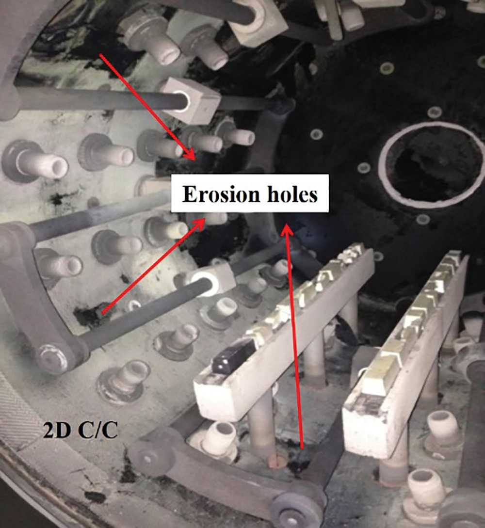
Figure 1: Erosion of 2D C/C composites in high-pressure gas quenching furnace
Generally, two methods are available for solving the above problem; one is increasing material compactness [6], and the other is preparing protective coatings for the materials [7,8]. For 2D C/C composites, densification processes mainly include chemical vapor deposition and liquid impregnation. Chemical vapor infiltration is a time-consuming process (usually more than 100 h) and is expensive [9]. Liquid impregnation requires several repetitions and high impregnation pressure for further densification, which imposes high cost due to increased requirements for materials [10]. The above mentioned two densification methods cannot enhance the erosion resistance of 2D C/C composites due to increased manufacturing cost, which may weaken the advantage of the material. Compared with densification, the coating method has many advantages such as property improvement, high performance and cost effective, and secondary treatment for reutilization. Therefore, protective coatings are very suitable tools to meet the requirement of high erosion resistance.
Several coatings have been investigated for improving the erosion resistance of porous C/C composites. Carbon-based coatings and claddings exhibit superior erosion resistance to unprotected composites and improve erosion resistant ability to varying extents [11,12]. Ceramic coatings, including SiC, TiC and SiO2–Al2O3–Y2O3, have been fabricated by several methods to be applied in C/C composites and revealed significantly stronger anti-erosion property than substrates with one order of magnitude greater erosion rates [13–15]. Graphite coating has the same composition with 2D C/C composites, and may not bring other pollution in the requirement of high purity environment for the thermal field. Also, it has obvious advantages including physical and chemical compatibility and better bonding strength compared with other coatings. Therefore, graphite coating is commonly used as pre-coating and coating in carbon materials. In addition, graphite coating can decrease the porosity of the surface of such materials, improving their erosion resistance. Today, graphite coating can be fabricated by several methods, such as slurry-sintering, sol-gel, deposition, and spaying [16–18]. Among these methods, the slurry method has many advantages, such as easy process, easy operation, low cost, and controllable thickness.
In this research, graphite coatings were prepared on the sample surface according to the slurry method. The microstructure and erosion performance of graphite coatings were also examined. The influence of slurry composition on coating performance was investigated. Finally, the features of graphite coatings were observed and erosion mechanisms were analyzed.
2.1 Preparation of Graphite Coating for 2D C/C Composites
Substrate samples (60 × 60 × 8 mm3) were cut from bulk 2D C/C (Shanghai Jingchi Carbon Co., Ltd., Shanghai, China). The samples were then polished with #400 SiC paper and dried at 373 K for 4 h after ultrasonically cleaning in distilled water. Graphite coatings were synthesized using slurry technology because of their various advantages such as simple operation and short production cycle. Phenolic resin (45.2% carbon yield, Shandong Shengquan Chemical Industry Co., Ltd., Jinan, China) and fine graphite (particle size of 3.5–4 μm, Shanghai Yifan Grahite Co., Ltd., Shanghai, China) were adequately mixed at a certain proportion. Then, the mixed powders were dissolved in ethanol with a weight ratio of 1:1 and mixed for 30 min. The as-prepared slurry was applied on the surface of C/C composites with a brush. The coating thickness was adjusted by brush coating times. Samples were cured at 393 K for 2 h, then carbonized and graphitized in an argon atmosphere for 3 h at 1473 K and 1923 K, respectively.
Phase compositions of graphite coatings were studied by X-ray diffraction (XRD) method on Bruker D8 Focus. The morphologies of graphite coatings were observed by scanning electron microscope (SEM, ZEISS SUPRA 55).
Erosion tests were performed by a gas-blast apparatus according to reference [15]. Alumina particles with flaky and angular morphologies are universally used in this field due to their high hardness which can cause large erosion rates. During erosion tests, alumina particles with an average size of 120 μm and flow rate of 50 mg/s were adopted as eroded particles. Particle velocity was tested using rotating double disks and adjusted by air pressure. In this test, air pressure and speed were set at 0.15 MPa and about 25 m/s, respectively. Fig. 2a illustrates the schematic diagram of the erosion testing device. This test was carried out under impact angles of 30° and 90°, and the results are shown in Fig. 2b.
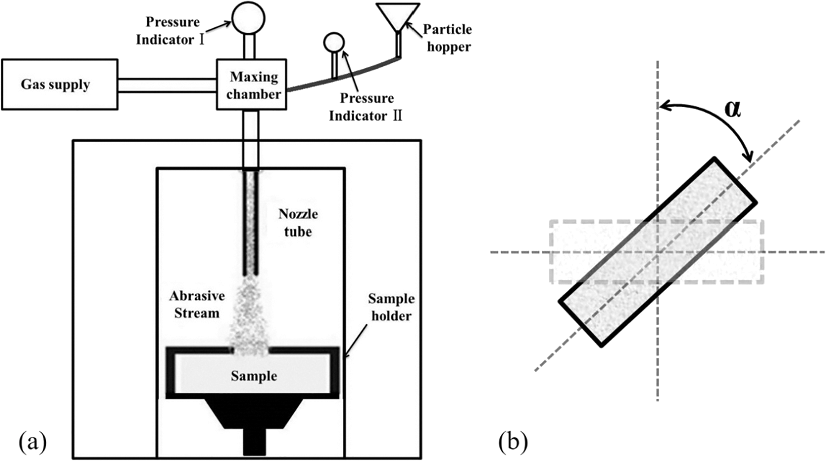
Figure 2: Schematic diagram of erosion device (a) and erosion angle (b)
Target specimens were 25 × 25 × 8 mm3 in size. Erosion tests were carried out at room temperature. The samples were ultrasonically cleaned with ethanol, weighed accurately, and subsequently placed on erosion test bench support. Erosion frequency was once every 5 s and samples were weighed to determine mass change. The erosion rate was determined according to the proportion of mass loss due to erosion and mass dissipation of erodent particles. Erosion surface micro morphology of the coating was inspected by SEM.
3.1 Microstructure of Graphite Coatings
Fig. 3 shows the macrograph of uncoated and graphite-coated 2D C/C composites. According to the results presented in this figure, the surface of the graphite coating was bright gray with gloss and was relatively smooth with no obvious cracks. When graphite powder is introduced into the system, many interfaces can be formed in graphite coating, which can relieve thermal stress due to volume shrinkage. Moreover, the interfaces may greatly reduce the number and size of cracks, creating a relatively compact coating.
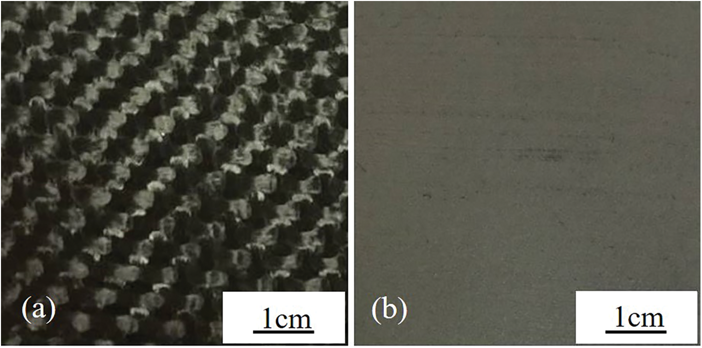
Figure 3: Macrograph of uncoated (a) and graphite-coated (b) 2D C/C
XRD results of samples and graphite coating are shown in Fig. 4. A weak and broad peak appeared, which was characteristic of disordered carbon and reflected that the crystallinity of the substrate was low. After graphite coating, the typical (002) diffraction peak at 26.5 of graphite crystal became sharper, and those of (100) and (004) appeared.
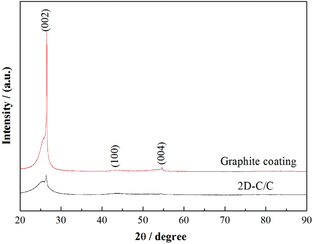
Figure 4: XRD results of sample and graphite coating
Fig. 4 presents SEM images of the surface and cross-section of graphite coating. From Figs. 4a and 4c, the coating was seen to be composed of flake graphite and the carbon derived from phenolic resin was relatively dense and continuous, which was different from substrate surface characteristics. However, many pores were seen on the coating, which might be mainly caused by irregular stacking of flake graphite powder and incomplete filling with resin-pyrolytic carbon. From Figs. 5b and 5d, graphite coating thickness was about 50 μm. Coating slurry penetrated into the substrate and bonded the fibers together, resulting in the densification of the 2D C/C composite skin layer to a certain extent. However, fiber bundles were still loose and there were obvious gaps among fibers in the substrate where the slurry was not penetrated. Surface densification could be expected to enhance erosion resistance capacity.
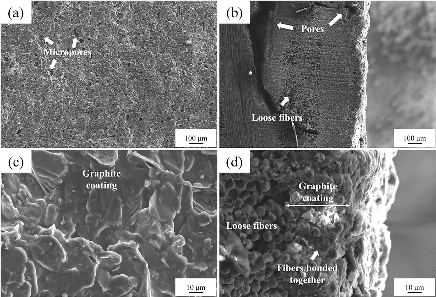
Figure 5: Micrographs of graphite coating: (a) and (c) surface, (b) and (d) cross-section
To study the relation between slurry composition and erosion resistance of graphite coatings, three coating types with different weight ratios of graphite and phenolic resin were prepared. Weight ratios were set to 1:3, 2:2, and 3:1. Fig. 6 exhibits the SEM images of graphite coatings. With the increase of graphite weight ratio, graphite coating porosity was gradually decreased, while coating density was increased. From Fig. 6a, it was seen that abundant cracks and fibers were created on the surface of 2D C/C composites. However, as the graphite weight ratio was increased, the cracks and exposed fibers were completely covered by graphite coating, and the flatness of the graphite coating surface gradually decreased. At the same time, it was observed that some bumps (Fig. 6e), with similar morphology to “ridge”, were formed on the graphite coating surface. This phenomenon could be explained by the fact that when graphite powder content was small (low weight ratio), coating slurry had low viscosity and could easily penetrate into the substrate during the brushing process, resulting in the ineffective covering of the surface by the coating; therefore, some fibers were exposed. Also, cracks on the coating were produced due to large volume shrinkage during the carbonization process of phenolic resin. With higher graphite powder contents in the slurry, the carbon yield of the coating was increased, which could fill cracks and make graphite coating denser. On the other hand, graphite powder increased the viscosity and decreased the fluidity of the coating slurry; therefore, the slurry was prone to form a dense coating. At too high of graphite powder contents, the fluidity of coating slurry was remarkably decreased, resulting in uneven spreading of slurry on the substrate surface; therefore, it was easy to form some “ridges” along the trace of the brushing process.
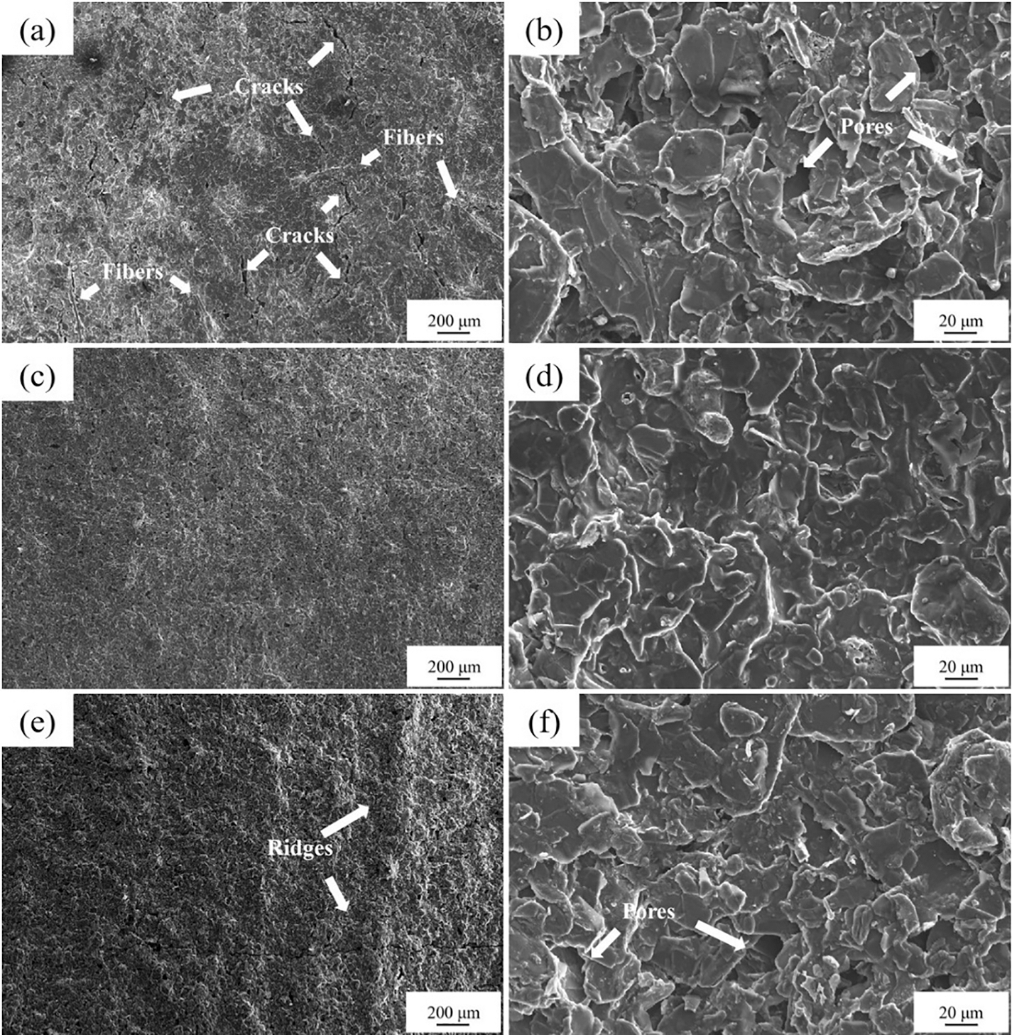
Figure 6: SEM images of the graphite coatings synthesized with different weight ratios of graphite powder and phenolic resin (a) and (b) 1:3, (c) and (d) 2:2, (e) and (f) 3:1
3.2 Erosion Resistance of Graphite Coatings
Fig. 7 shows the erosion mass loss curves of graphite coatings on samples at 30° and 90° impact angles. It was seen that graphite coating improved substrate erosion resistance at both normal and oblique impact angles. In addition, the extent of the erosion performance improvement of graphite coating was determined by the weight ratios of graphite powder and phenolic resin. After 50 s, the erosion resistance of graphite coating was first increased and then decreased by increasing the graphite powder content. With the graphite weight ratio increased, the erosion mass loss of the graphite coatings decreased 28.7%, 41.5%, 8.6% at 30° impact angle and 40.8%, 52.3%, 19.2% at 90° impact angle, respectively. This result reflected the fact that graphite coating showed better erosion resistance at an impact angle of 90° compared to that at 30°. At the 1:1 weight ratio of the two components, graphite coating showed the highest erosion protective ability. The erosion rate curves of graphite coatings at impact angles of 30° and 90° are illustrated in Fig. 8. The erosion rates of graphite coating were 17.2 mg/g at 30° impact angle and 23.3 mg/g at 90° impact angle. According to comparison results, coating treatment enhanced anti-erosion property by about 41.5% at the impact angle of 30° and 52.3% at normal impact. With longer erosion times, the erosion rates of primary samples remained relatively constant, while that index of graphite-coated samples had an obvious change interval. Moreover, that index of graphite-coated samples also remained constant before and after the change interval, and the erosion rate was larger in the early stage than in the late stage. Variation of erosion rate for graphite-coated specimens meant that the erosion mechanism was changed significantly.
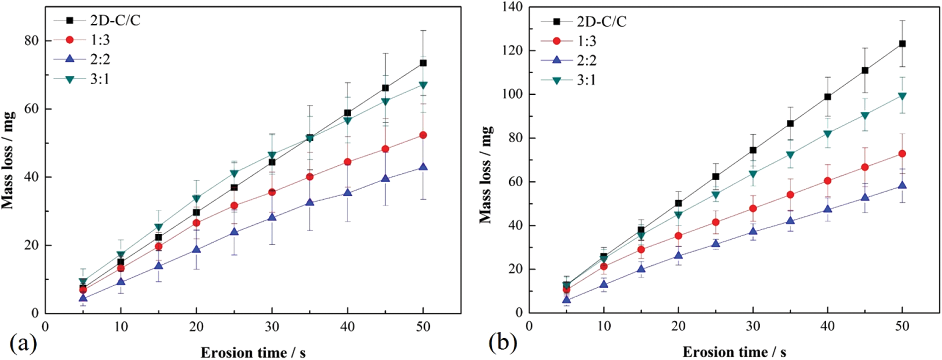
Figure 7: The erosion mass loss curves of graphite coating at different impact angles (a) 30° and (b) 90°
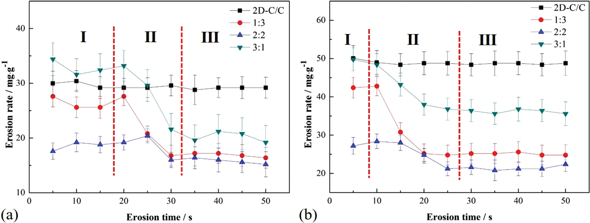
Figure 8: The erosion rate curves of graphite coating for C/C materials with various impact angles (a) 30° and (b) 90°
According to the variations of erosion rate curves, the erosion process of graphite-coated 2D C/C included three stages. In the first stage (region I), solid particles accelerated and impacted graphite coating, the erosion mass loss of samples was mainly the graphite coating. In the last stage (region III), graphite coating was worn out and solid particles began to impact the interfacial bond layer between substrate and coating, resulting in the removal of bond layer materials. At this stage, the specimen erosion rate was significantly decreased, which might be caused by interfacial bond layer densification by slurry infiltration in the process of coating preparation. In stage (II), there was a transition region that revealed the mixed erosion of graphite coating and interfacial bond layer.
Furthermore, even graphite-coated specimens with graphite and phenolic resin weight ratio of 3:1 in coating slurry exhibited larger erosion rates compared to that of the substrate in the initial stage of the erosion process. This was because graphite is soft and is easily fractured and delaminated by solid particles impacting repeatedly, which may increase the specimen erosion rate. As the graphite coating was completely removed, solid particles directly impacted on the substrate, decreasing the erosion rate. Therefore, the erosion rate of graphite-coated specimens was greater in the early erosion stage than that in the last erosion stage. At 30° impact angle, there were many “ridges” composed of graphite powder, which were easily cracked by oblique impact, and demonstrated large erosion rates.
3.3 Erosion Mechanism of Graphite Coatings
The macromorphology of erosion scar for graphite-coated 2D C/C composites under various impact angles is shown in Fig. 9. Under different impact angles, specimen direction is accordingly changed. In this impact experiment, particle flow divergence at different impact angles was also observed. Previous erosion-related studies have found that particle flow divergence was increased at low-impact angles, which led to the formation of an oval depression [19,20].
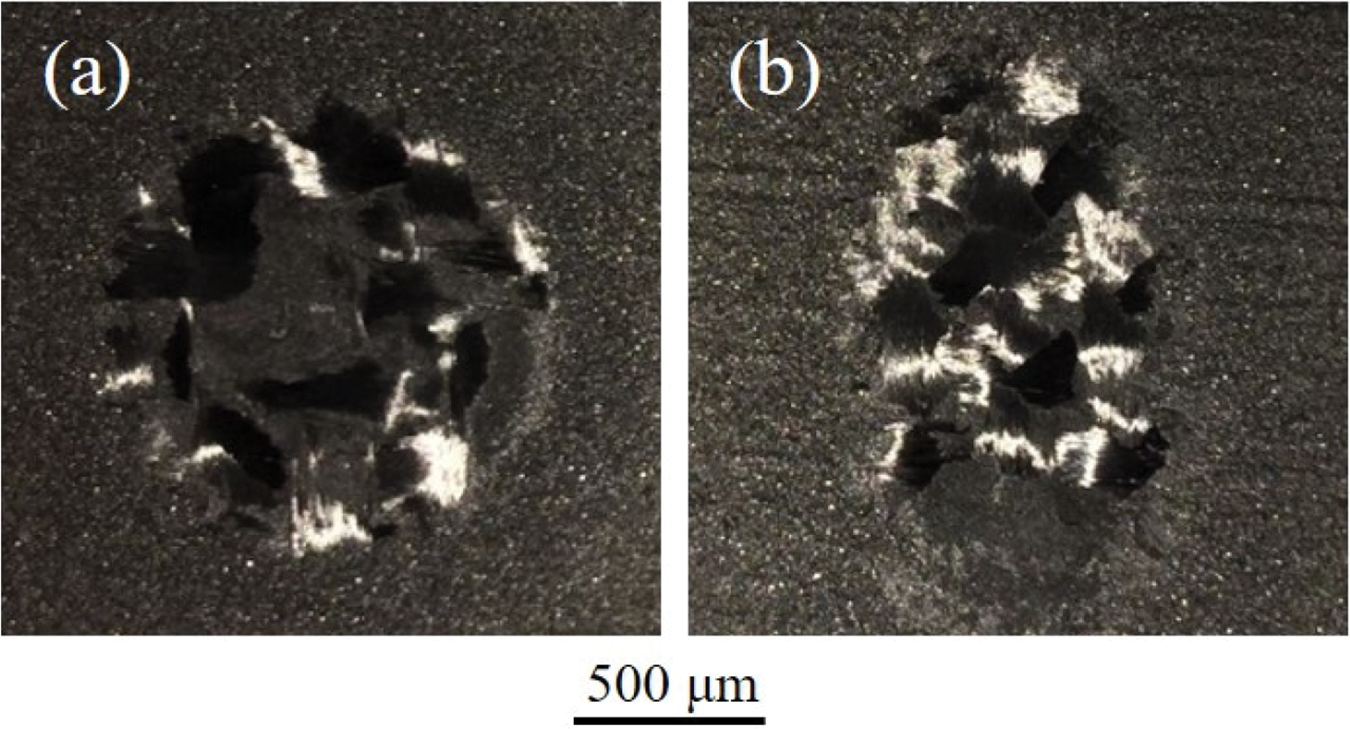
Figure 9: Macrographs of graphite coating for specimens after erosion at various impact angles (a) 90°: circle, (b) 30°: ellipse
Figs. 10 and 11 present the SEM images of the eroded surfaces of graphite-coated specimens at 30° and 90° impact angles, respectively. Graphite coatings were severely damaged and worn out in the central area of erosion at both oblique and normal impact angles. Additionally, the coatings fracture, the fibers breakage can also be seen from the edge and center erosion region. In the early erosion stage, the coating replaced substrate erosion, which might provide protection at a certain amount for 2D C/C composites. It had a significant effect on improving the stability of composite materials and better met the requirements of thermal insulation performance. At 30° impact angle (Fig. 10), ploughing marks were observed parallel to the erosion direction, while coating fracture was presented perpendicular to the erosion direction. From high magnification SEM micrographs (Figs. 10b and 10d), fibers exhibited cutting damage. At 90° impact angle (Fig. 11), ploughing marks disappeared and the erosion mechanism in this circumstance mainly consisted of graphite coating fracture and fiber breakage.
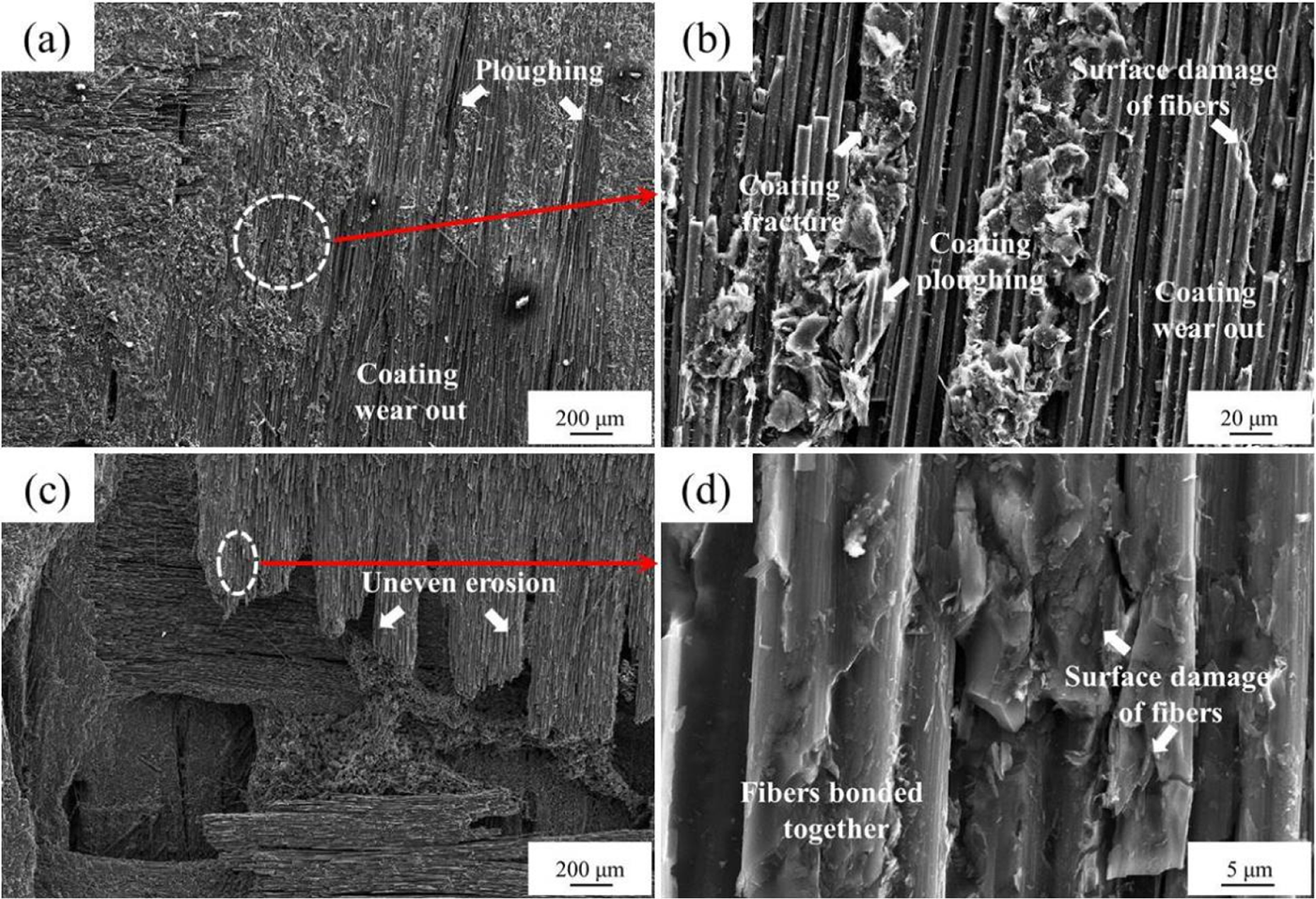
Figure 10: Erodent surface morphologies of specimens with graphite coating at 30° impact angle: (a) and (b) the edge of erosion scar, (c) and (d) the center of erosion scar
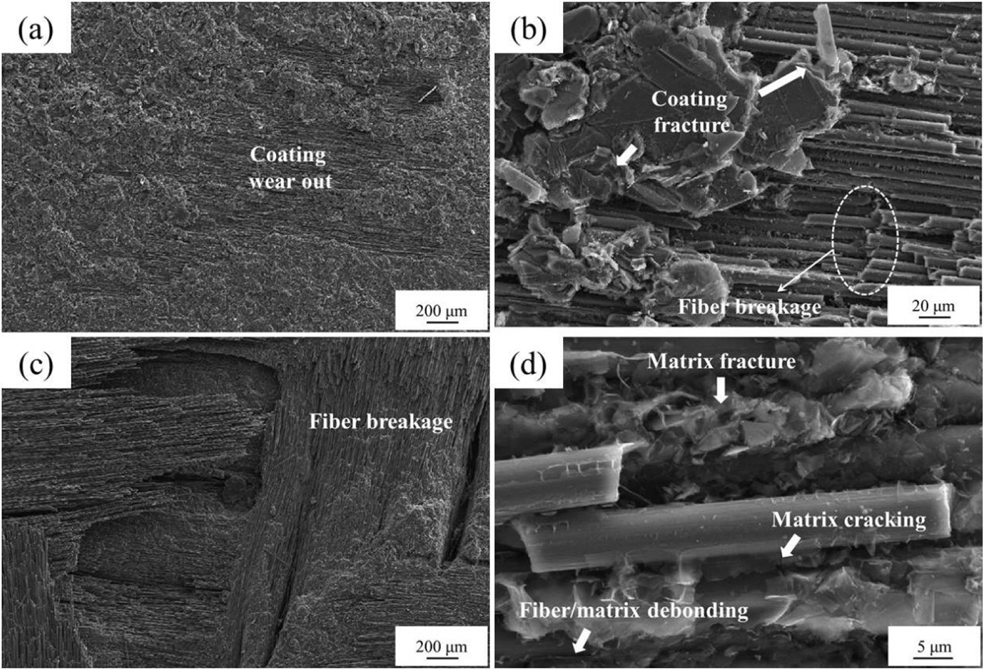
Figure 11: Erodent surface morphology of graphite-coated specimens at 90° impact angle: (a) and (b) the edge of erosion scar, (c) and (d) the center of erosion scar
For graphite-coated samples, the main impact factors of erosion resistance were as follows: (I) Graphite coating took the place of matrix erosion in the early stage, providing protection for 2D C/C samples. (II) Coating slurry filled pores and cracks on the matrix surface, which caused a stronger 2D C/C surface than substrate. (III) Coating slurry could penetrate the substrate and bond carbon fibers, which not only increased the number of interfaces obtained from coating slurry, but also provided enough support for fibers [21,22]. At this time, even if the fibers were broken, they were still bonded with the substrate, as shown in Fig. 12a. Furthermore, the delamination of the fractured fibers needed to destroy more interfaces (Fig. 12b), which might prevent crack initiation and propagation during the erosion process and increase the breakage energy required for fiber debonding. Therefore, the erosion resistance ability graphite-coated 2D C/C samples was obviously enhanced.
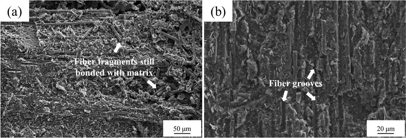
Figure 12: Typical micromorphology of fibers after erosion: (a) fibers fragments, and (b) fibers removal
2D C/C materials were modified for erosion resistance by graphite coating according to a low-cost slurry method. With the increase of graphite powder/phenolic resin weight ratio, the porosity and smoothness of the coating gradually decreased, while its density evidently increased. The erosion resistance of graphite coatings was first increased and then decreased. The graphite coating prepared with equal weight ratios of graphite powder and phenolic resin exhibited the best anti-erosion property, which obviously decreased the erosion rate of 2D C/C samples by about 41.5% and 52.3% at impact angles of 30° and 90° after 50 s erosion, respectively. The improvement of graphite coating on the anti-erosion property could be explained by the fact that coating replaced the matrix to erosion in the early erosion stage, and coating slurry infiltrated into the composites, enhancing the fiber bonding and increasing the interfaces, which can prevent the initiation and propagation of cracks during the late erosion process. The morphologies eroded surfaces revealed that the major erosion mechanisms of graphite-coated 2D C/C samples were graphite coating fracture, fiber breakage, and fiber/matrix debonding. Furthermore, the erosion mechanism involved the ploughing of carbon fiber bundles and cutting of the carbon fiber surface at an oblique impact angle.
Acknowledgement: The authors would like to thank all supporters and reviewers who provide constructive and detailed critique.
Funding Statement: This paper has obtained the support of the National Natural Science Foundation of China (No. 51902039), High-Level Talents Innovation Support Plan of Dalian (No. 2020RQ127), and Scientific Research Project of Liaoning Provincial Department Education (No. LJKZ0722).
Author Contributions: The authors confirm contribution to the paper as follows: study conception and design: Wei Shi and Ju Heng; data collection: Zhengyi Li; analysis and interpretation of results: Yingshui Yu and Xiaofei Ding; draft manuscript preparation: Xiaobing Xu. All authors reviewed the results and approved the final version of the manuscript.
Availability of Data and Materials: The data that support the findings of this study are available from the corresponding author upon reasonable request.
Conflicts of Interest: The authors declare that they have no conflicts of interest to report regarding the present study.
References
1. Schmidt, D. L., Davidson, K. E., Theibert, L. S. (1999). Unique applications of carbon-carbon composite materials. Sample Journal, 35(3), 27–39. [Google Scholar]
2. Li, C. J., Crosky, A. (2006). The effect of carbon fabric treatment on delamination of 2D-C/C composites. Composites Science and Technology, 66(15), 2633–2638. https://doi.org/10.1016/j.compscitech.2006.03.025 [Google Scholar] [CrossRef]
3. Yang, X., Li, H. J., Yu, K. H., Zhang, S. Y. (2013). Effect of stress level on fatigue behavior of 2D C/C composites. Transactions of Nonferrous Metals Society of China, 23(7), 2135–2140. https://doi.org/10.1016/S1003-6326(13)62708-9 [Google Scholar] [CrossRef]
4. Luo, R. Y., Huai, X. L., Qu, J. W., Ding, H. Y., Xu, S. H. (2003). Effect of heat treatment on the tribological behavior of 2D carbon/carbon composites. Carbon, 41(14), 2693–2701. https://doi.org/10.1016/S0008-6223(03)00291-4 [Google Scholar] [CrossRef]
5. Bogachev, E., Elakov, A. (2022). Organomorphic carbon-carbon composite for hot pressing molds. International Journal of Applied Ceramic Technology, 19(1), 101–107. https://doi.org/10.1111/ijac.13813 [Google Scholar] [CrossRef]
6. Baxter, R. I., Rawlings, R. D., Iwashita, N., Sawada, Y. (2000). Effect of chemical vapor infiltration on erosion and thermal properties of porous carbon/carbon composite thermal insulation. Carbon, 38(3), 441–449. https://doi.org/10.1016/S0008-6223(99)00125-6 [Google Scholar] [CrossRef]
7. Fang, M., Ma, Y. J., Zhang, N., Huang, M., Lu, B. et al. (2020). Solid particle erosion resistance and electromagnetic shielding performance of carbon fiber reinforced polycarbonate composites. Materials Research Express, 7(4), 045305. https://doi.org/10.1088/2053-1591/ab6fa6 [Google Scholar] [CrossRef]
8. Maurer, C., Schulz, U. (2013). Erosion resistant titanium based PVD coatings on CFRP. Wear, 302(1–2), 937–945. https://doi.org/10.1016/j.wear.2013.01.045 [Google Scholar] [CrossRef]
9. Zhao, J. G., Li, K. Z., Li, H. J., Wang, C. (2006). The influence of thermal gradient on pyrocarbon deposition in carbon/carbon composites during the CVI process. Carbon, 44(4), 786–791. https://doi.org/10.1016/j.carbon.2005.08.030 [Google Scholar] [CrossRef]
10. Jana, B., Rajulapati, K. V., Prasad, N. E., Jain, R. K., Rao, K. B. S. (2016). Effect of carbon fabric type on properties of 2D carbon-carbon composites processed by liquid pitch impregnation-pyrolysis. Journal of Composite Materials, 50(23), 3239–3254. https://doi.org/10.1177/0021998315617817 [Google Scholar] [CrossRef]
11. Baxter, R. I., Rawlings, R. D. (1997). Microstructure and solid particle erosion of carbon-based materials used for the protection of highly porous carbon-carbon composite thermal insulation. Journal of Materials Science, 32(17), 4485–4492. https://doi.org/10.1023/A:1018656814398 [Google Scholar] [CrossRef]
12. Alajmi, A. F., Ramulu, M. (2021). Solid particle erosion of graphene-based coatings. Wear, 476(S1), 203686. https://doi.org/10.1016/j.wear.2021.203686 [Google Scholar] [CrossRef]
13. Smeacetto, F., Salvo, M., Ferraris, M., Casalegno, V., Canavese, G. et al. (2009). Erosion protective coatings for low density, highly porous carbon/carbon composites. Carbon, 47(6), 1511–1519. https://doi.org/10.1016/j.carbon.2009.01.045 [Google Scholar] [CrossRef]
14. Shi, W., Tan, Y., Hao, J. J., Li, J. Y. (2016). Microstructure and anti-erosion property of SiC coated 2D C/C composites by chemical vapor reaction. Ceramics International, 42(15), 17666–17672. https://doi.org/10.1016/j.ceramint.2016.08.083 [Google Scholar] [CrossRef]
15. Shi, W., Tan, Y., Hao, J. J., Li, J. Y. (2018). Effect of precoated carbon layer on microstructure and anti-erosion properties of SiC coating for 2D-C/C composites. International Journal of Applied Ceramic Technology, 15(3), 592–601. https://doi.org/10.1111/ijac.12841 [Google Scholar] [CrossRef]
16. He, Q. C., Li, H. J., Yin, X. M., Lu, J. H. (2021). Effect of PyC shell thickness on the microstructure, ablation resistance of SiCnws/PyC-C/C-ZrC-SiC composites. Journal of Materials Science & Technology, 71, 55–66. https://doi.org/10.1016/j.jmst.2020.08.047 [Google Scholar] [CrossRef]
17. He, Q. C., Li, H. J., Tan, Q., Lu, J. H., Wang, Y. Q. (2021). Influence of carbon preform density on the microstructure and ablation resistance of CLVD-C/C-ZrC-SiC composites. Corrosion Science, 190, 109648. https://doi.org/10.1016/j.corsci.2021.109648 [Google Scholar] [CrossRef]
18. He, Q. C., Li, H. J., Tan, Q., Lu, J. H., Yin, X. M. (2022). Effects of ZrC particle size on ablation behavior of C/C-SiC-ZrC composites prepared by chemical liquid vapor deposition. Corrosion Science, 205, 110469. https://doi.org/10.1016/j.corsci.2022.110469 [Google Scholar] [CrossRef]
19. Coto, B., Hallander, P., Mendizabal, L., Pagano, F., Kling, H. et al. (2021). Particle and rain erosion mechanisms on Ti/TiN multilayer PVD coatings for carbon fibre reinforced polymer substrates protection. Wear, 466, 203575. https://doi.org/10.1016/j.wear.2020.203575 [Google Scholar] [CrossRef]
20. Ozzaim, P., Korkusuz, O. B., Fidan, S., Sinmazcelik, T. (2022). Investiagtion of particle erosion of polytetrafluoroethylene and its composites. Journal of Materials: Design and Applications, 236, 1738–1749. https://doi.org/10.1177/14644207221081964 [Google Scholar] [CrossRef]
21. Bao, L. M., Maruyama, Y., Shi, J. (2022). Mechanisms of solid particle erosion damage in the repair of damaged composites structures. Advanced Composite Materials, 31(4), 385–389. https://doi.org/10.1080/09243046.2021.2018090 [Google Scholar] [CrossRef]
22. Jing, W. W., Zhang, F., Chen, H. (2022). Comparative tribological performance and erosion resistance of epoxy resin composite coatings reinforced with aramid fiber and carbon fiber. Collids and Surfaces A: Physicochemical and Engineering Aspects, 648(10), 129354. https://doi.org/10.1016/j.colsurfa.2022.129354 [Google Scholar] [CrossRef]
Cite This Article
 Copyright © 2024 The Author(s). Published by Tech Science Press.
This work is licensed under a Creative Commons Attribution 4.0 International License , which permits unrestricted use, distribution, and reproduction in any medium, provided the original work is properly cited.
 Downloads
 Citation Tools