
 Submit a Paper
 Propose a Special lssue
 Open Access
ARTICLE

Effect of Nozzle Inclination Angle on Fuel-Air Mixing and Combustion in a Heavy Fuel Engine
School of Transportation and Vehicle Engineering, Shandong University of Technology, Zibo, 255049, China
* Corresponding Author: Jian Meng. Email:
Fluid Dynamics & Materials Processing 2024, 20(2), 365-382. https://doi.org/10.32604/fdmp.2023.030302
Received 30 March 2023; Accepted 27 June 2023; Issue published 14 December 2023
 View Full Text
 Download PDF
Abstract
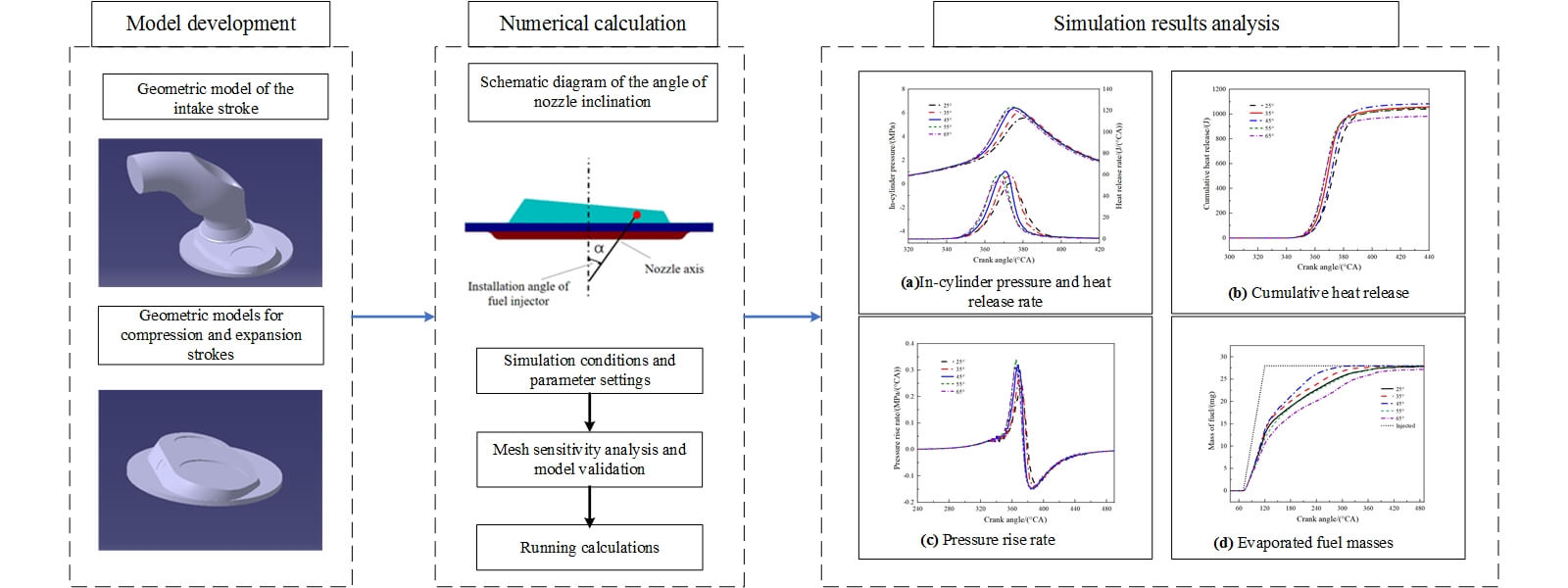
Heavy-fuel engines are widely used in UAVs (Unmanned Autonomous Vehicles) because of their reliability and high-power density. In this study, a combustion model for an in-cylinder direct injection engine has been implemented using the AVL FIRE software. The effects of the angle of nozzle inclination on fuel evaporation, mixture distribution, and combustion in the engine cylinder have been systematically studied at 5500 r/min and considering full load cruise conditions. According to the results, as the angle of nozzle inclination increases, the maximum combustion explosion pressure in the cylinder first increases and then it decreases. When the angle of nozzle inclination is less than 45°, the quality of the mixture in the cylinder and the combustion performance can be improved by increasing the angle. When the angle of nozzle inclination is greater than 45°, however, the mixture unevenness increases slightly with the angle, leading to a deterioration of the combustion performances. When the angle of nozzle inclination is between 35° and 55°, the overall combustion performance of the engine is relatively good. When the angle of nozzle inclination is 45°, the combustion chamber’s geometry and the cylinder’s airflow are well matched with the fuel spray, and the mixture quality is the best. Compared with 25°, the peak heat release rate increases by 20%, and the maximum combustion burst pressure increases by 5.5%.Graphic Abstract
Keywords
Nomenclature
| CA | Crank angle |
| TDC | Top dead center |
| ATDC | After top dead center |
| BTDC | Before top dead center |
| CFD | Computational fluid dynamics |
| FDD | Flame development duration |
| RCD | Rapid combustion duration |
At present, the main fuel for aviation piston engines for UAVs is aviation gasoline because of technical limitations [1]. In comparison with gasoline, aviation kerosene exhibits characteristics including a high flash point, low volatility, and high viscosity [2–4]. This makes heavy-fuel aviation piston engines more suitable for special occasions. But in a spark ignition engine, the knocking of kerosene is a very serious risk because of its low octane number [5,6]. In addition, the kinematic viscosity of aviation kerosene is higher, resulting in poor atomization of fuel droplets. Thus, it is difficult to form a uniform mixture, which leads to a reduction of combustion quality [7,8]. However, the angle of nozzle inclination can directly affect the distribution and mixing of fuel in the engine cylinder, which is of great significance for the efficient combustion of the fuel. Therefore, it is important to study the influence of the angle of nozzle inclination on heavy-fuel aviation piston engines to improve their overall performance [9].
The effects of the angle of nozzle inclination on fuel-air mixing and combustion have been studied by several researchers. Lu et al. [10] carried out numerical simulations of injection strategies at 10 different injection positions and angles of nozzle inclination for aviation heavy fuel direct injection engines. The results showed that the flow field in the engine cylinder has an important effect on the atomization and distribution of aviation heavy fuel. Pan et al. [11] proved that different angles of nozzle inclination affect initial flame propagation time, which in turn plays an important role in calculating the subsequent flame’s spread to nearby fuel injections. Sharma et al. [12] used the scramjet engine as the study’s object and studied the influence of the change in nozzle inclination angle on combustion performance. Armin et al. [13] studied the combustion stage of reactive control compression ignition by changing the injection times and angle of nozzle inclination of dual-fuel heavy diesel engines. Mano Alexander et al. [14] predicted the effective injection mode of fuel by obtaining the optimal direction of the injector and analyzing its orientation using computational fluid dynamics (CFD). Payri et al. [15] reproduced the combustion chamber’s density conditions at the start of the injection of a high-density gas (SF6)-pressurized vessel at room temperature. Based on this device, the influence of the angle of nozzle inclination on diesel spray characteristics was studied. Ji et al. [16] established and verified the CFD model of gasoline direct injection rotary engines. This model was used to study the impact of various injection sites and nozzle inclination angles on mixture generation and combustion. Farajollahi et al. [17] investigated the effects of creating rotational flow and adjusting the nozzle angle on the performance and emissions of tracked diesel engines in two phases using AVL FIRE software. Cong et al. [18] investigated how the Isuzu 4BD1T diesel engine’s performance and exhaust emissions were affected by fuel injection parameters such as nozzle inclination angles, injection pressure, and injection start. Renald et al. [19] used a CFD program to investigate the influence of geometric parameters such as nozzle diameter and angle of nozzle inclination on the performance and emission characteristics of dual-fuel engines. Li et al. [20] investigated how the nozzle angle affected the injection mass and flow rate and reported that the fuel mass of a single nozzle increases with a reduction in the angle of nozzle inclination. The sensitivity of the internal flow characteristics to the angle of nozzle inclination increases as the angle of nozzle inclination is reduced.
In summary, researchers have investigated how nozzle inclination affects the formation and combustion of gasoline and diesel engine mixtures in order to improve engine performance. However, the research on the effect of nozzle inclination on aviation heavy fuel piston engine performance is not systematic, especially the study on the effect of fuel-air mixing and combustion, which needs to be further explored. In particular, the effects of fuel-air mixing and combustion need to be further explored. As a result, a direct injection aviation heavy fuel piston engine is chosen as the research subject to methodically examine the impact of nozzle inclination angle on engine performance and provide a fundamental theoretical backing for engine improvement.
2 Model Establishment and Verification
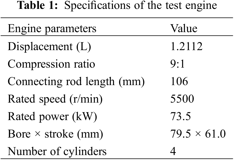
The in-cylinder direct injection aviation heavy fuel piston engine is chosen as the study’s object. The primary technical parameters of the engine are presented in Table 1.
At 5500 r/min and full load cruising conditions, the airflow movement, spray process, and processes of mixture formation and combustion in the engine cylinder were simulated by CFD calculations. The compression top dead center was defined as 360°CA. The initial crankshaft angle was calculated as the intake valve opening time (0°CA). The end crankshaft angle was calculated as the exhaust valve opening time (492°CA). The maximum calculation step was set to 1°CA and the minimum was set to 0.5°CA.
In the calculation process, the center differential scheme is used for continuity equations and dynamic equations. The SIMPLE algorithm is used in pressure-velocity coupling schemes in flow field solving [17].The energy equation, the flux control equation, and the linear solving equation use the upwind difference scheme [21]. The finite volume method is used to discretize the flow control equation [22].
2.1 The Establishment of Geometric Model and Definition of Basic Parameters
The aviation piston engine was modeled according to the structure mapping data on the prototype combustion system. The entire simulation procedure excludes an exhaust stroke, so the exhaust valve and exhaust port structure were not considered, and the exhaust seat was closed [23]. The three-dimensional models of its airway, valve, combustion chamber, and piston top were established. The geometric model of the engine is shown in Fig. 1.
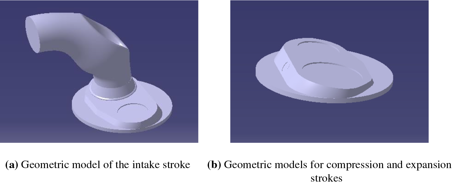
Figure 1: Geometric model of the engine
The two sections shown in Fig. 2 were mainly selected for analysis to facilitate the observation of the three-dimensional calculation results of the engine combustion system. Sections 1 and 2 were defined as Y-Cut and X-Cut sections, respectively.
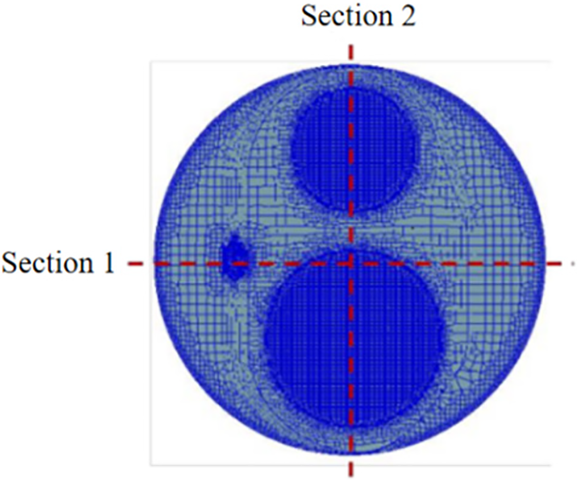
Figure 2: Schematic diagram of section selection position
The angle between the axis of the injector nozzle and the axis of the cylinder is defined as the angle of nozzle inclination. A schematic diagram of the angle of nozzle inclination is shown in Fig. 3. The angle of nozzle inclination determines the direction of the fuel spray in the cylinder. It has a significant impact on the mixing of the fuel droplets and the airflow in the cylinder. An appropriate angle of nozzle inclination can realize the expected macroscopic spatial distribution of fuel in the combustion chamber and make fuel droplets evaporate rapidly. This has an important influence on improving the quality of the mixture. Renald et al. [19] investigated the effects of different nozzle inclination angles (180°, 30°, 45°, and 90°) on engine performance and emission traits. They concluded that a 30° nozzle angle produced the best performance. Krishna et al. [24] investigated the effects of the intake manifold dip angles (0°, 30°, 60°, and 90°) on the cylinder’s flow characteristics under various intake valve lift situations using particle image velocimetry. The findings indicate that the turbulent kinetic energy of all intake valve lifts is at its greatest when the manifold dip angle is 60°. Therefore, the effects of angles of nozzle inclination of 25°, 35°, 45°, 55°, and 65° on the procedure for fuel-air mixing and the characteristics of combustion were analyzed in this study.
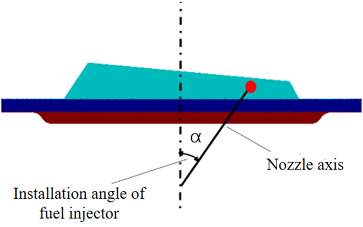
Figure 3: Schematic diagram of the angle of nozzle inclination
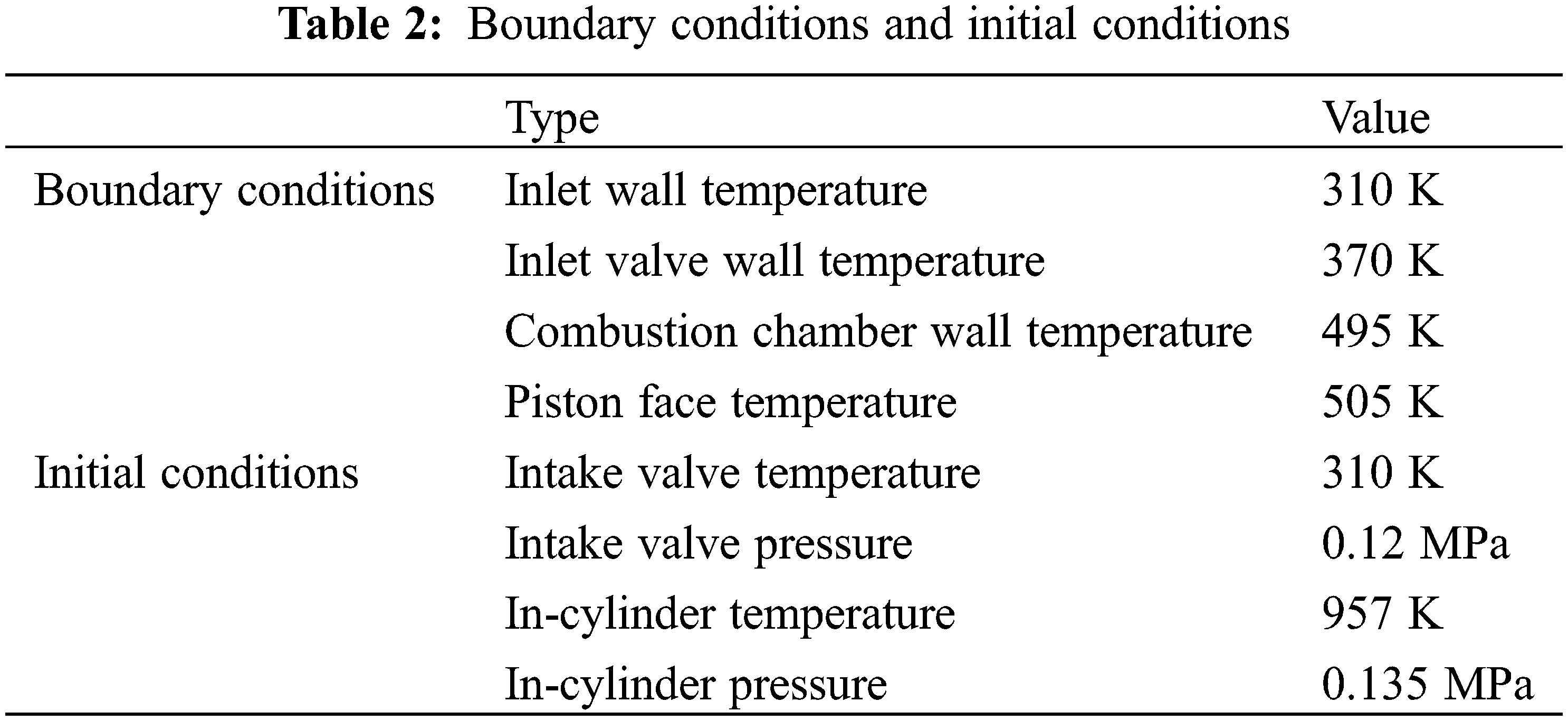
2.2 Boundary Conditions and Initial Conditions
The boundary and initial conditions of the aviation heavy fuel piston engine chosen as this study’s object are presented in Table 2.
2.3 Model Selection and Verification
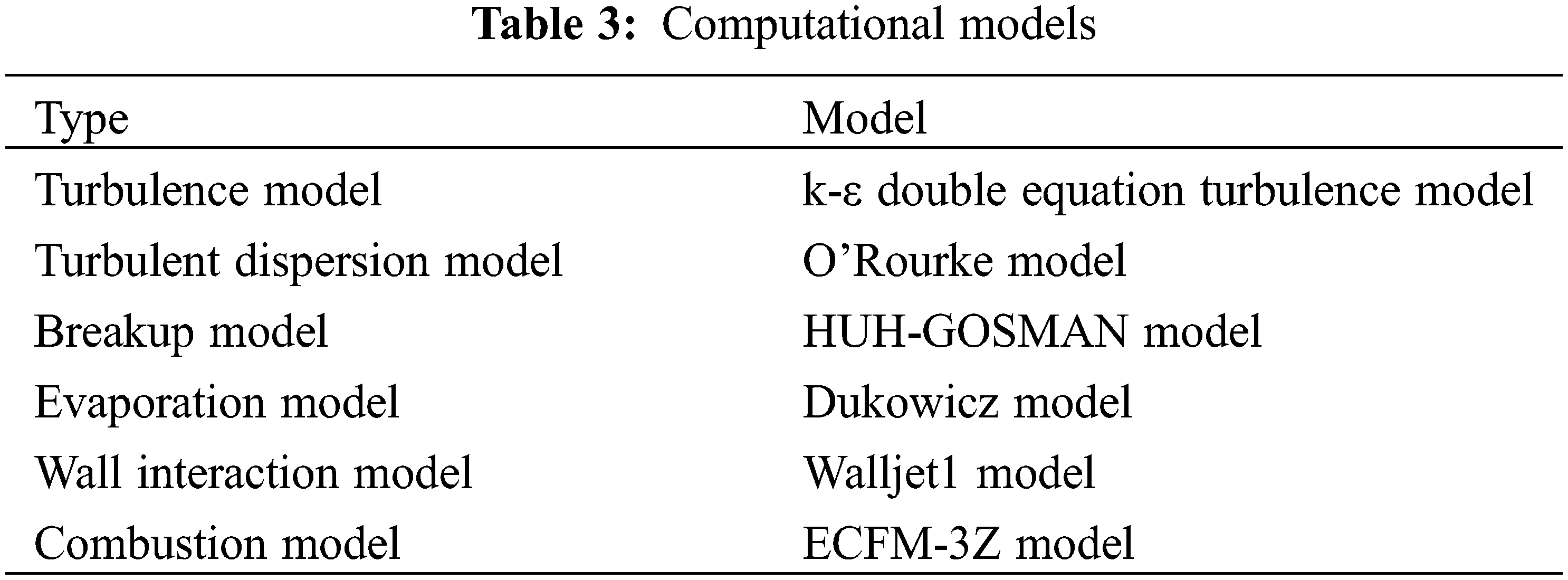
The computational models in AVL FIRE software [25], such as the turbulence model and spray model, are presented in Table 3. The Huh-Gosman model was used as a turbulent diffusion model to simulate the flow process of fuel to the nozzle [26,27]. The Dukowicz’s evaporation model considers droplet evaporation in a non-condensable gas. Therefore, it uses a gas-phase, two-component system consisting of steam and non-condensing gases [28,29]. The ECFM-3Z model is a universal combustion model that can simulate the intricate processes of turbulent mixing and pollutant release specific to engines. This model can simulate turbulent premixed and diffused combustion using the flame surface density transport equation [30]. The k-ε turbulence model is used to describe the fluid motion in the cylinder. The model can be used to describe the complex turbulent flow field [31]. The Walljet1 model is based on engine operating conditions in which a vapor buffer forms beneath the droplets, which bounce or slide along the wall. Because wall membrane physics is unimportant in the process of wall contact, this model disregards the physical properties of the wall film [32]. The O’Rourke model is chosen as the turbulent diffusion model in this paper. Instead of reducing the time step of the spray integration, the wave component is set to zero, but the new particle position and new particle velocity are calculated as Gaussian distributions for each component [33,34].
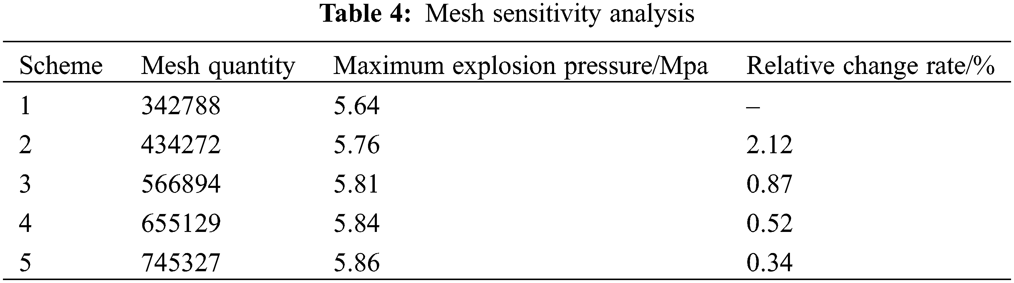
When CFD calculation is carried out on AVL FIRE, subregion processing is required for the imported surface mesh, including boundary, initial condition, motion, refinement, and output result parts. When the pre-treated combustion chamber model is divided into body grids, the mesh parameters of the key parts such as the valve, valve seat, and spark plug are further optimized to ensure the generation of a better mesh. The mesh quality directly affects the simulation results, so it is necessary to determine an optimal mesh size. As shown in Table 4, with the further refinement of the mesh, no significant change has been observed in the simulated maximum blasting pressure from the mesh of Scheme 3 to Scheme 5. In order to save computational time, Scheme 3 grid is considered in this study and used for all simulations.
In-cylinder pressure is the index that can best reflect the performance of the engine [35]. The curve of in-cylinder pressure and heat release rate was adopted to verify the accuracy of the calculation model in this study. The engine was connected to the Xiangyi GW160 electric eddy current dynamometer, the FC2210 intelligent fuel consumption meter, the AVL combustion analyzer, and other equipment to form the whole experimental bench. The experimental bench is shown in Fig. 4.
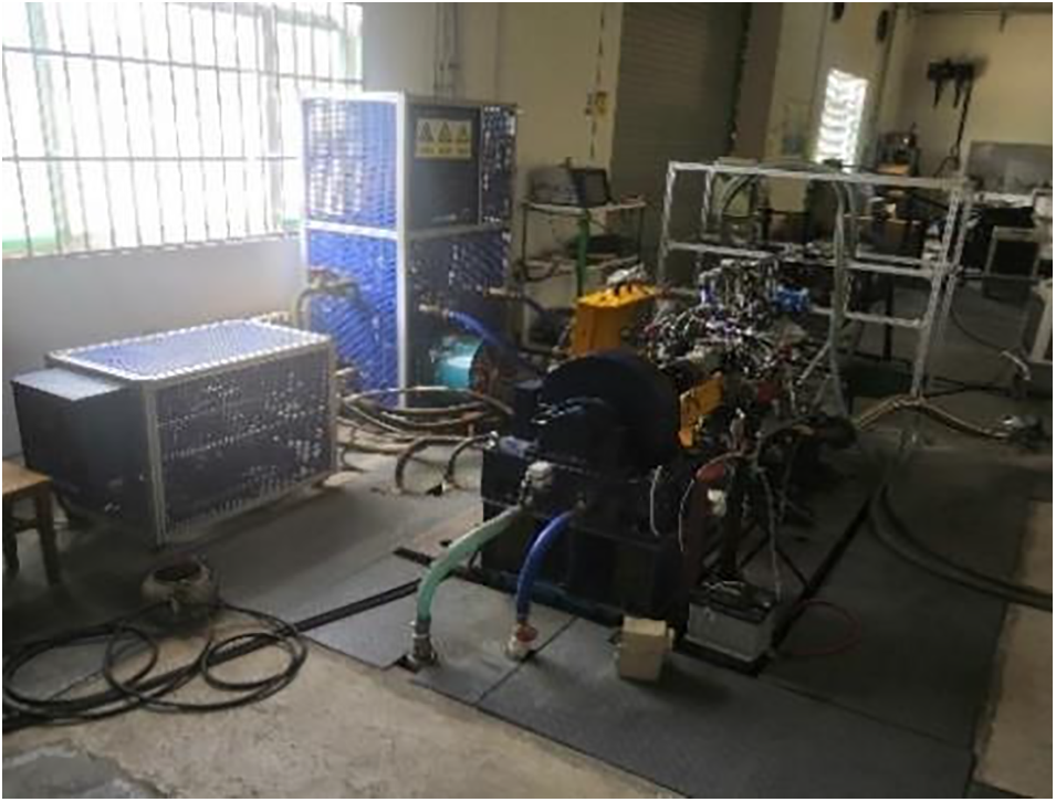
Figure 4: Experiment platform
As shown in Fig. 5, the heat release curve of the simulated value was relatively consistent with that of the experimental value. The peak value of the simulation-derived cylinder pressure and heat release rate curve was less than the actual value, with a maximum error of 3.2%, although the cylinder pressure curve’s phase was nearly identical. The results showed that the simulation model has high accuracy and can be used to predict the performance of aviation heavy-fuel piston engines.
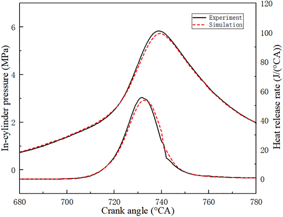
Figure 5: Validation of mean in-cylinder pressure and heat release rate
3.1 Effect of Angle Nozzle Inclination Angle on Fuel-Air Mixing Characteristics
The plot of the evaporated fuel masses at different angles of nozzle inclination is shown in Fig. 6. There was marginal difference in the evaporation rate of the fuel under different angles of nozzle inclination during the injection duration of 70°CA–120°CA. After injection, the speed of fuel evaporation initially increased before decreasing with the increase in nozzle inclination. When the angle of nozzle inclination was 45°, the best fuel evaporation was obtained, and the fuel droplets were completely evaporated before the ignition time. However, when the angle of nozzle inclination was 55°, the fuel evaporation rate decreased significantly, and a small amount of fuel was not completely evaporated at the ignition time. When the angle of nozzle inclination was 65°, the fuel evaporation in the cylinder was less than the injection amount. The reason is that the angle of nozzle inclination is too large, leading to an increase in the wet wall phenomenon, and part of the fuel does not evaporate in time during the upward process of the piston.
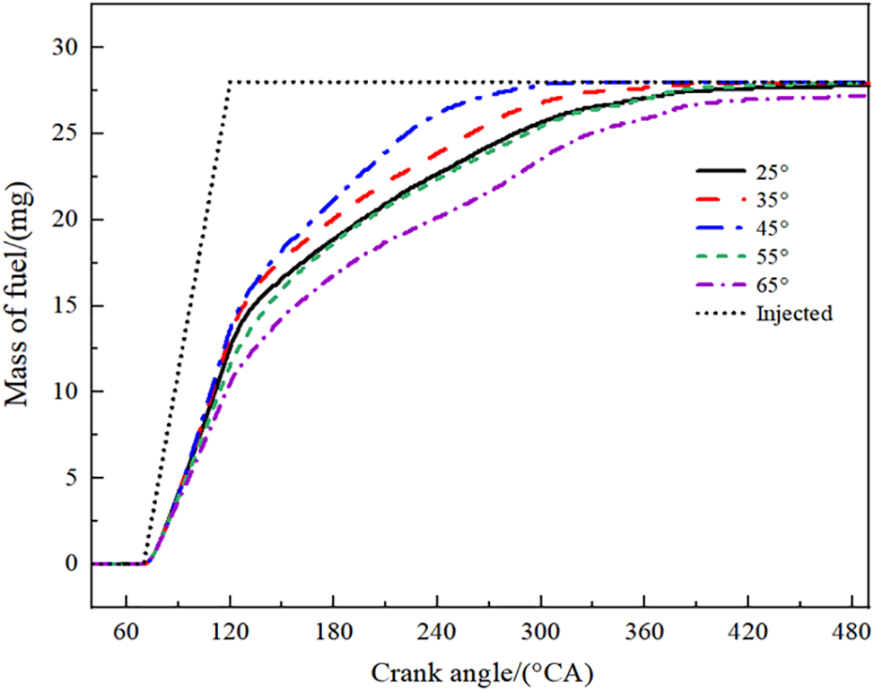
Figure 6: Evaporated fuel masses at different angles of nozzle inclination
The changing process of in-cylinder air/fuel mixing at different angles of nozzle inclination is shown in Fig. 7. After injection begins, 75°CA is the 5°CA. The fuel spray movement direction gradually moves to one side wall of the spark plug with the increase in the angle of nozzle inclination. At the same time, the position of the fuel spray hits the wall and gradually moves from the top surface of the piston to the cylinder wall. The mixture diffuses counterclockwise to the top of the combustion chamber as the nozzle inclination increases from 25° to 35°, as can be seen from the concentration field distribution of 190°CA. This is caused by the tumbling flow in the cylinder. The mixture distribution near the cylinder center is relatively uniform, but there is a high concentration of fuel accumulation near the injector cylinder head and cylinder wall. When the angle of nozzle inclination is 45°, there is no excessive fuel accumulation area in the cylinder. When the angle of nozzle inclination is between 55° and 65°, the momentum of the fuel spray after hitting the cylinder wall decreases. This results in poor coupling between the fuel spray droplets and the flow movement. Therefore, the fuel droplets form a part of the oil-rich region near the cylinder wall of the injector side.
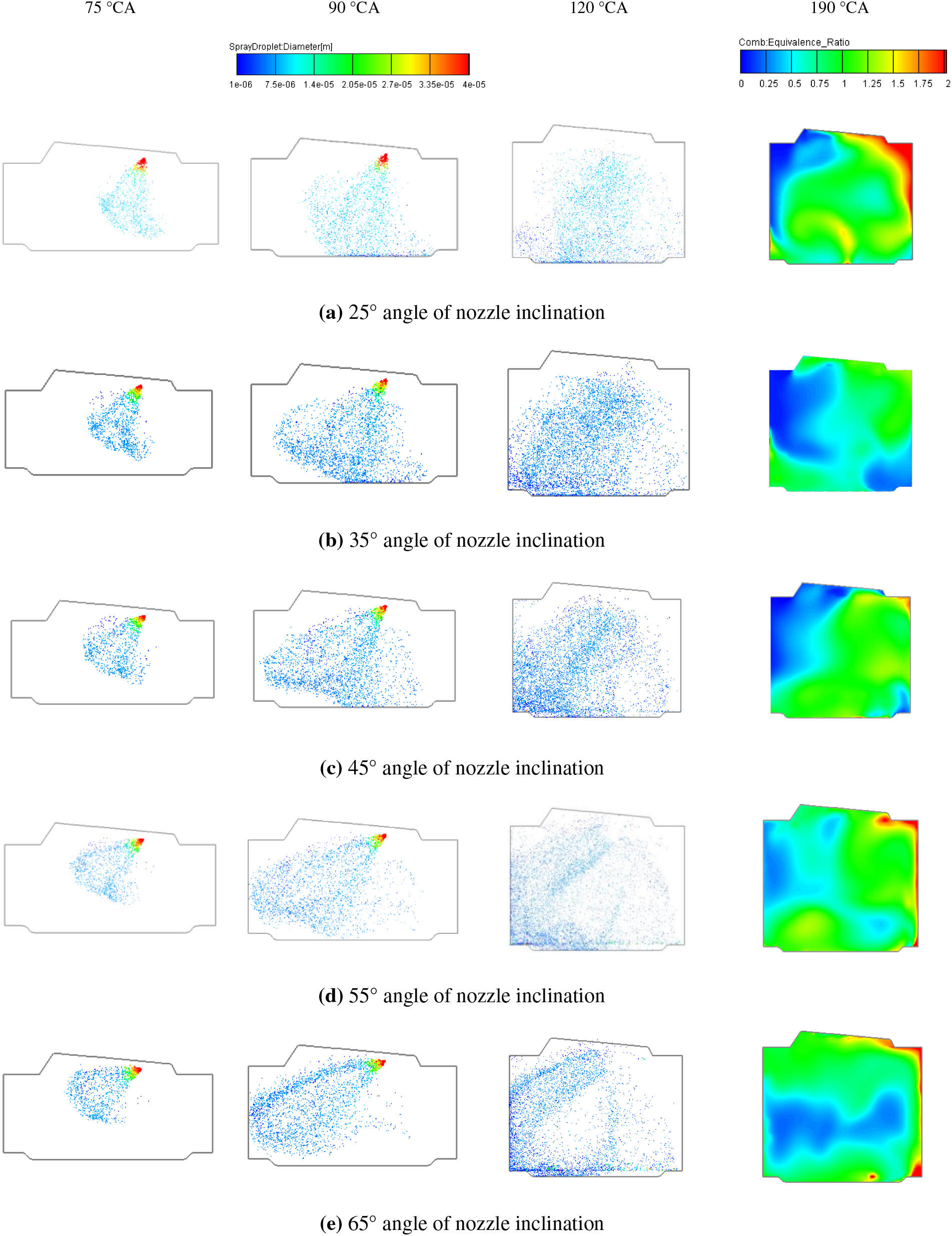
Figure 7: In-cylinder air/fuel mixing process at different angles of nozzle inclination
The mixture distribution in the cylinder at ignition timing under different angles of nozzle inclination is shown in Fig. 8. There is a great difference between the direction of spray movement and the flow in the cylinder because of the different angles of nozzle inclination. For the aviation piston engine with a small cylinder diameter, the mixture formation quality in the cylinder can be enhanced to some extent by increasing the angle of nozzle inclination. However, when the angle of nozzle inclination is greater than 45°, the mixture’s unevenness increases. As Fig. 8 illustrates, when the angle of nozzle inclination was 45°, the cylinder’s mixture distribution is largely uniform. However, when the angle of nozzle inclination is 55°, the mixture in the cylinder has a relatively large portion of overly thick and overly thin areas, resulting in poor quality of the mixture. When the angle of nozzle inclination is 65°, the fuel droplets form a more obvious concentration distribution in the combustion chamber space between the intake valve and the exhaust valve. This condition is not conducive to the organization of the combustion process.
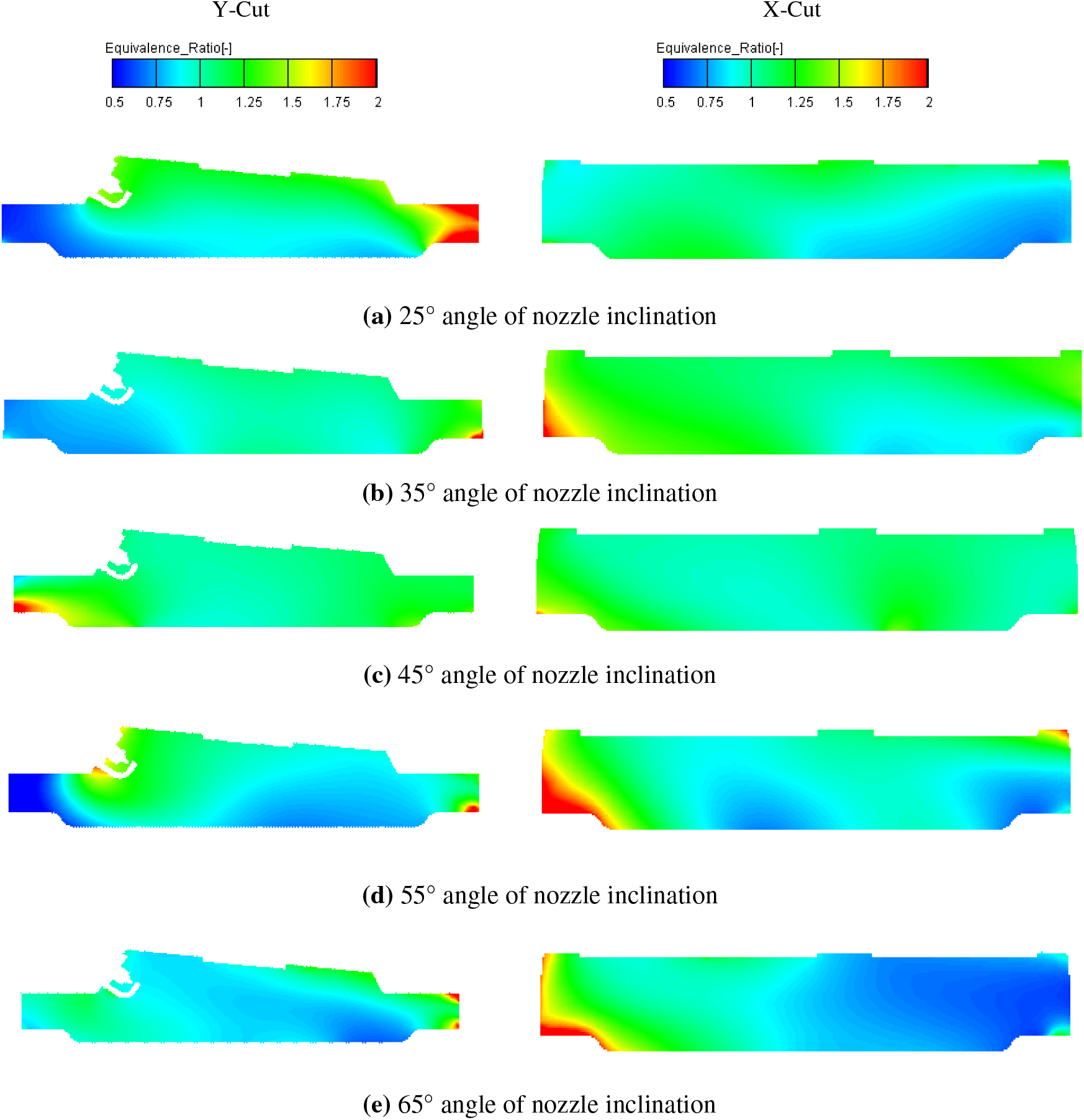
Figure 8: Distribution of mixture in-cylinder at ignition time under different nozzle inclination angles
The distribution of the flow field at various angles of nozzle inclination in the cylinder at top dead center is shown in Fig. 9. The tumbling flow gradually transitions from the upper region of the spark plug, which is located towards the top of the wedge-section combustion chamber, to the lower piston region as the angle of nozzle inclination increases. At the same time, the flow rate is increasing. The piston continues to go up, and the airflow in the cylinder is mainly tumbling flow and extrusion stream. When the angle of nozzle inclination is greater than 45°, the unevenness of the flow velocity in the combustion chamber increases. When the angle of nozzle inclination increases to 65°, there is a strong flow velocity in the upper region of the piston, which is not conducive to the stability of the combustion process.
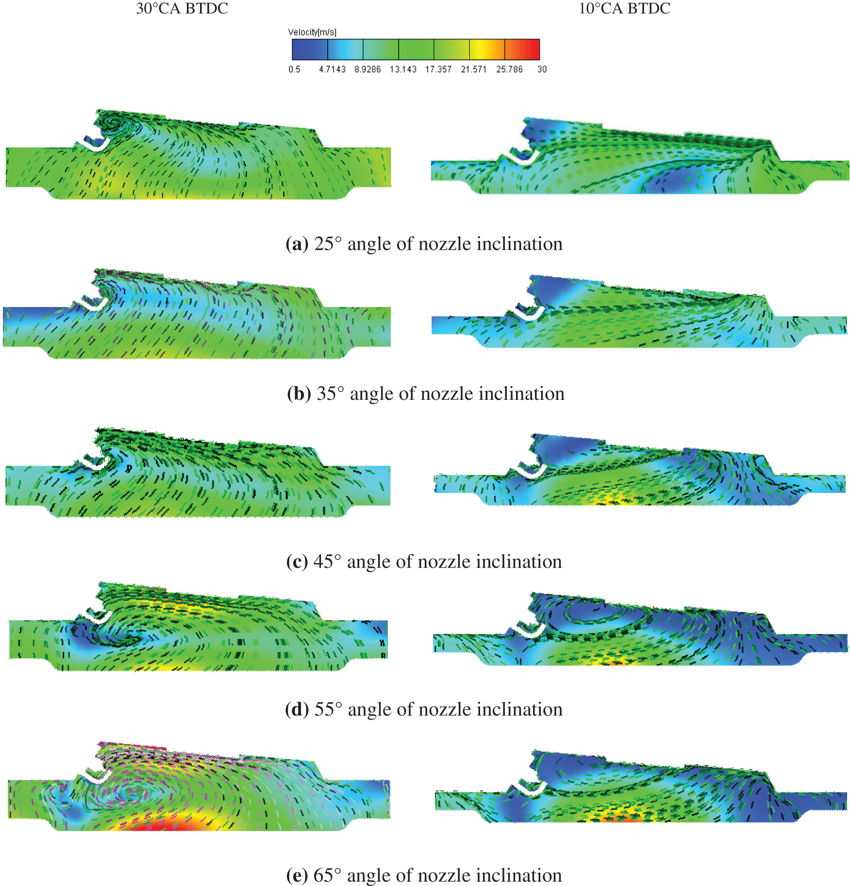
Figure 9: In-cylinder flow field distribution near TDC at different angles of nozzle inclination
The distribution of turbulent kinetic energy before and after ignition at various angles of nozzle inclination is shown in Fig. 10. With the increase in nozzle inclination angle, the turbulent kinetic energy in the combustion chamber increases continuously before and after ignition timing. However, the region and distribution of high turbulent kinetic energy are greatly different. High turbulence near the top dead center during ignition is critical to the engine combustion process. After ignition, fuel and air are consumed within a short time to avoid spontaneous combustion and knocking. When the angle of nozzle inclination increases from 25° to 45°, the distribution of the 30°CA BTDC turbulent kinetic energy shows that both the area with high turbulent kinetic energy and the turbulent kinetic energy itself are increasing. Around the rapid combustion period, the high turbulent kinetic energy area moves from the cylinder’s center to the combustion chamber’s right side via the spark plug. In this case, high turbulent kinetic energy is distributed more uniformly. This situation is conducive to speeding up flame propagation and improving combustion efficiency.
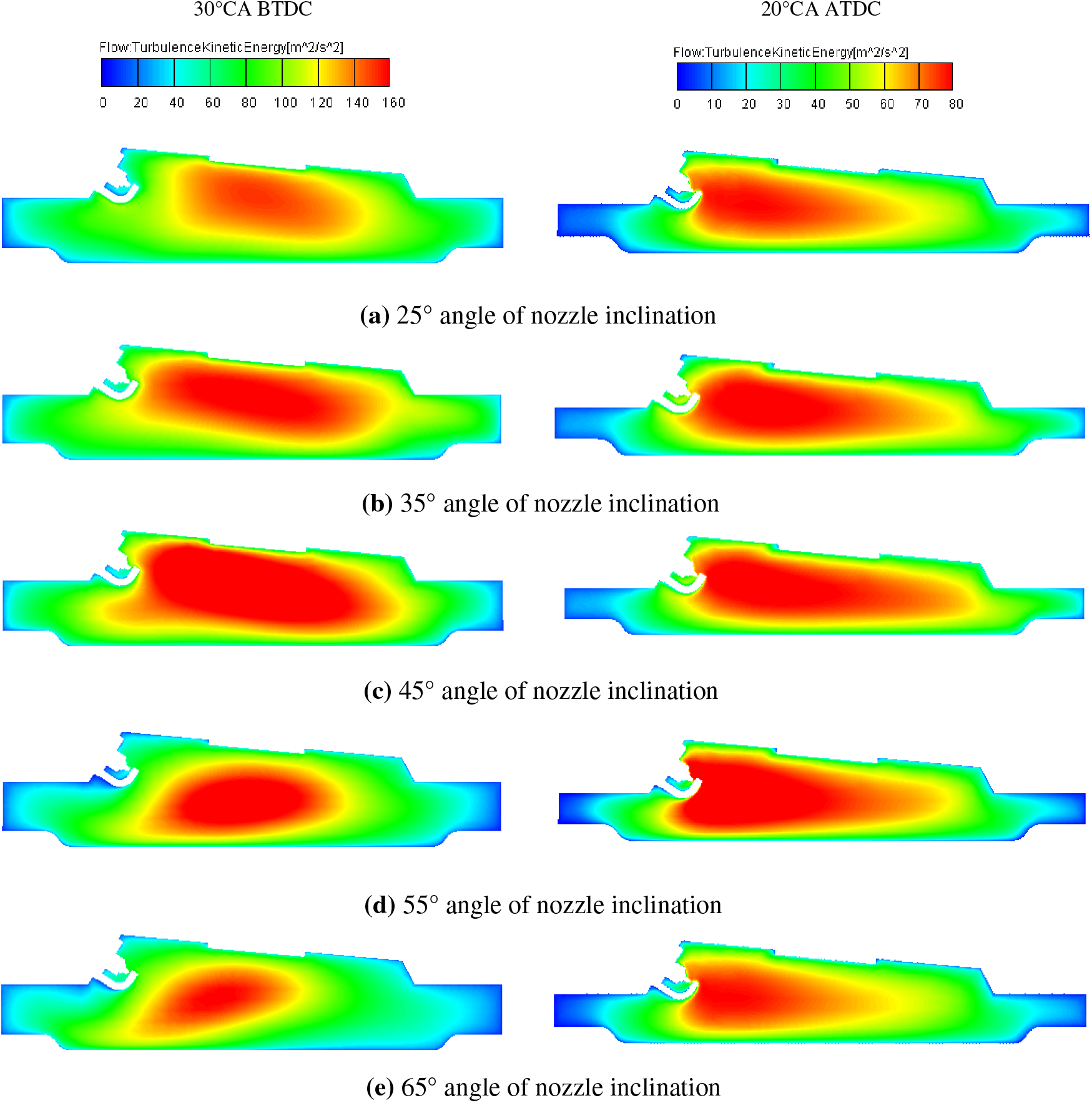
Figure 10: Turbulent kinetic energy distribution in the cylinder before and after ignition at different angles of nozzle inclination
When the angle of nozzle inclination is between 55° and 65°, the amount of turbulent kinetic energy does not significantly change, but the area with a high concentration of this energy diminishes. In the process of combustion, the turbulent kinetic energy fluctuates a little, but the area of high turbulent kinetic energy also decreases, which is not conducive to accelerating the heat release rate.
In summary, when the angle of nozzle inclination is between 35°–55°, the fuel-air mixing in the cylinder is better, which can provide an effective guarantee for good combustion.
3.2 Effect of Nozzle inclination Angle on Combustion Characteristics
The plots of the changes in the main parameters of the in-cylinder combustion process under different angles of nozzle inclination are shown in Fig. 11. With the increase in nozzle inclination, the maximum in-cylinder pressure first increases and then decreases. When the angle of nozzle inclination increases to 45°, the combustion condition in the cylinder is slightly improved by continuing to increase the angle of nozzle inclination. This is mainly due to the different directions of movement of the fuel spray and the instability of the airflow in the cylinder under increasing angles of nozzle inclination. When the angle of nozzle inclination is 45°, the peak value of the instantaneous heat release rate reaches the highest value of 63.11 J/(°CA). The reason is that there is basically no impact between the fuel spray and the combustion chamber wall at this angle of nozzle inclination, and the droplets evaporate and diffuse quickly. At the time of ignition, the mixture formed in the cylinder is relatively uniform, the heat release rate is accelerated, and the combustion center of gravity moves forward. When the angle of nozzle inclination is between 55° and 65°, there is no significant difference in the maximum combustion pressure in the cylinder. Although the combustion phase is further along, the rate of instantaneous and cumulative heat release is decreasing. The peak instantaneous heat release rate decreases by 5.29% and 14.32% compared with the angle of nozzle inclination of 45°. As Fig. 11d illustrates, when the angle of nozzle inclination is 65°, the in-cylinder temperature significantly decreases in comparison with other angles of nozzle inclination. The reason is that the excessively large angle of nozzle inclination will accelerate the time of fuel spray impact on the wall. As a result, the mixing time of the oil beam, as it evaporates in the cylinder, is shortened, and accumulation forms on the wall surface, resulting in insufficient combustion heat release.
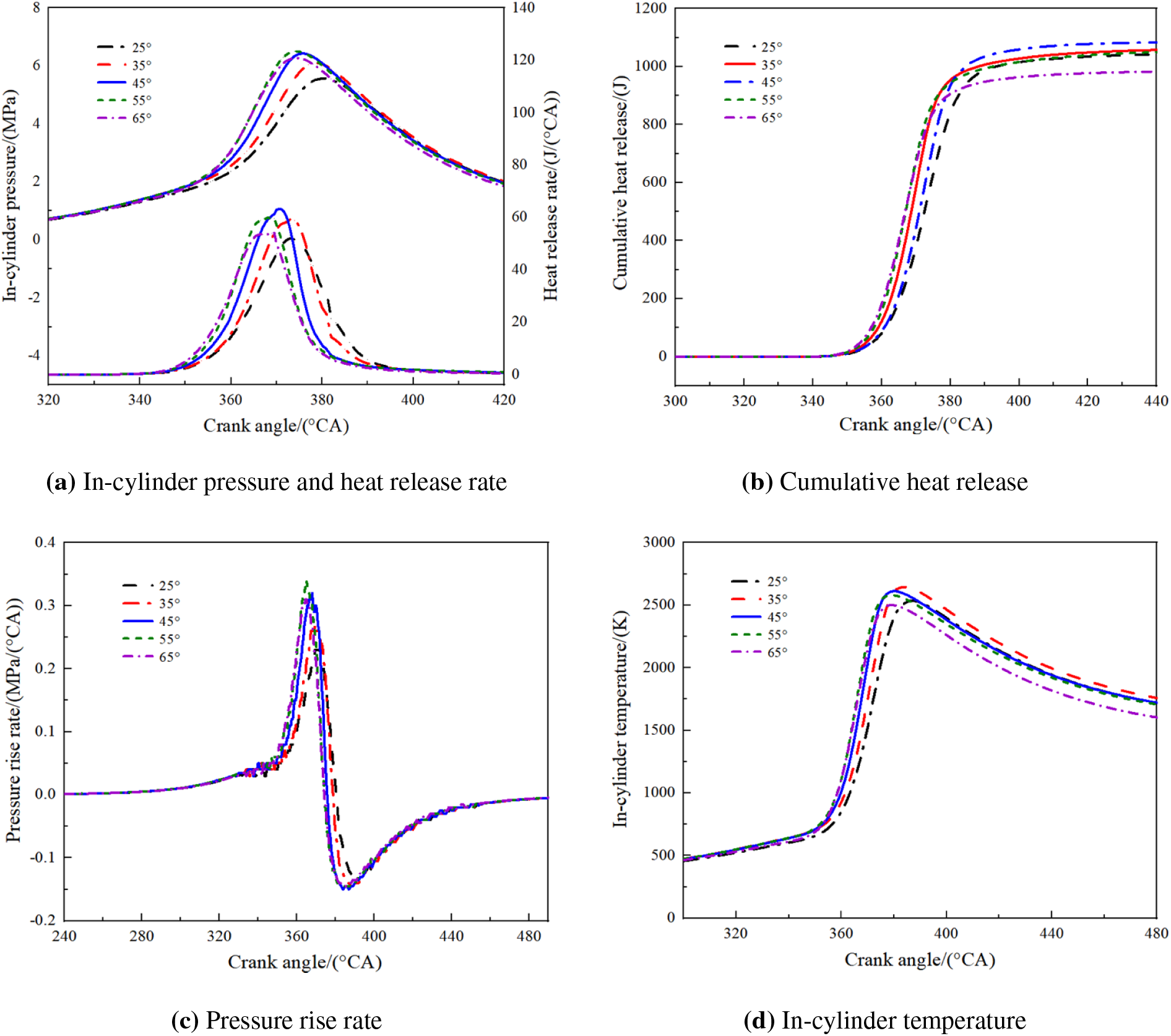
Figure 11: In-cylinder combustion process under different angles of nozzle inclination
The influence of different angles of nozzle inclination on the combustion phase is shown in Fig. 12. The crank angle (CA) is represented as CA10, CA50, and CA90 when the cumulative heat release reaches 10%, 50%, and 90%, respectively. The formula for calculating the rapid combustion duration (RCD) is RCD = |CA90 – CA10|, and the formula for calculating the flame development duration (FDD) is FDD = |CA10 − spark timing| [36]. When the angle of nozzle inclination increases from 25° to 65°, the starting point of combustion and the center of gravity of heat release tend to advance overall, and the end time of combustion first advances and then delays. The reason is that fuel evaporation first rises before falling. When the angle of nozzle inclination is 65°, there is incomplete evaporation, the fuel-air mixing quality is poor, the combustion quality is poor, and the rapid combustion period increases. When the angle of nozzle inclination is 45°, the combustion structure is better, and the ignition delay period and rapid combustion period are relatively short. The instantaneous heat release rate is at its maximum when the nozzle is inclined at an angle of 45°, as can be observed from the heat release rate curve. The reason is that the contact position between the oil beam and the wall and the amount of wall collision are different due to the different angles of nozzle inclination. When the angle of nozzle inclination is 45°, the fuel droplets accumulate less on the wall, and the evaporation process is faster. Therefore, the combustion process is relatively well organized, and the heat release is more concentrated.
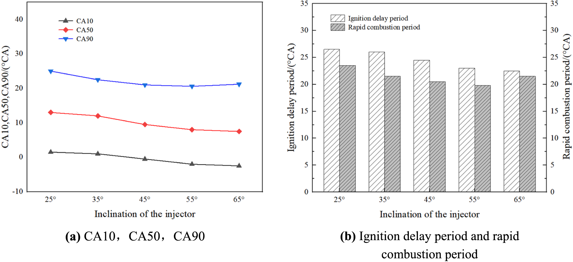
Figure 12: Effect of different angles of nozzle inclination on the combustion phase
The temperature distribution in the cylinder under different angles of nozzle inclination is shown in Fig. 13. Combined with the concentration field and flow field, when the nozzle’s inclination is between 45° and 55°, the fuel-air mixing in the cylinder is more sufficient, and there is no large range of fuel-rich area. At this time, the flow in the cylinder is more regular, which is conducive to the spread of the flame in the cylinder. Therefore, the temperature in the cylinder rises faster. Figure 10°CA ATDC depicts how the flame has reached the combustion chamber wall’s right side and how the high-temperature region is noticeably more inclined than other angles. When the angle of nozzle inclination is 65°, the high-temperature area in the cylinder decreases. The reason is that the excessively large angle of nozzle inclination leads to fuel collision with the wall in advance, and the quality of mixture formation is decreased. Therefore, the speed of flame propagation in the combustion process decreases.
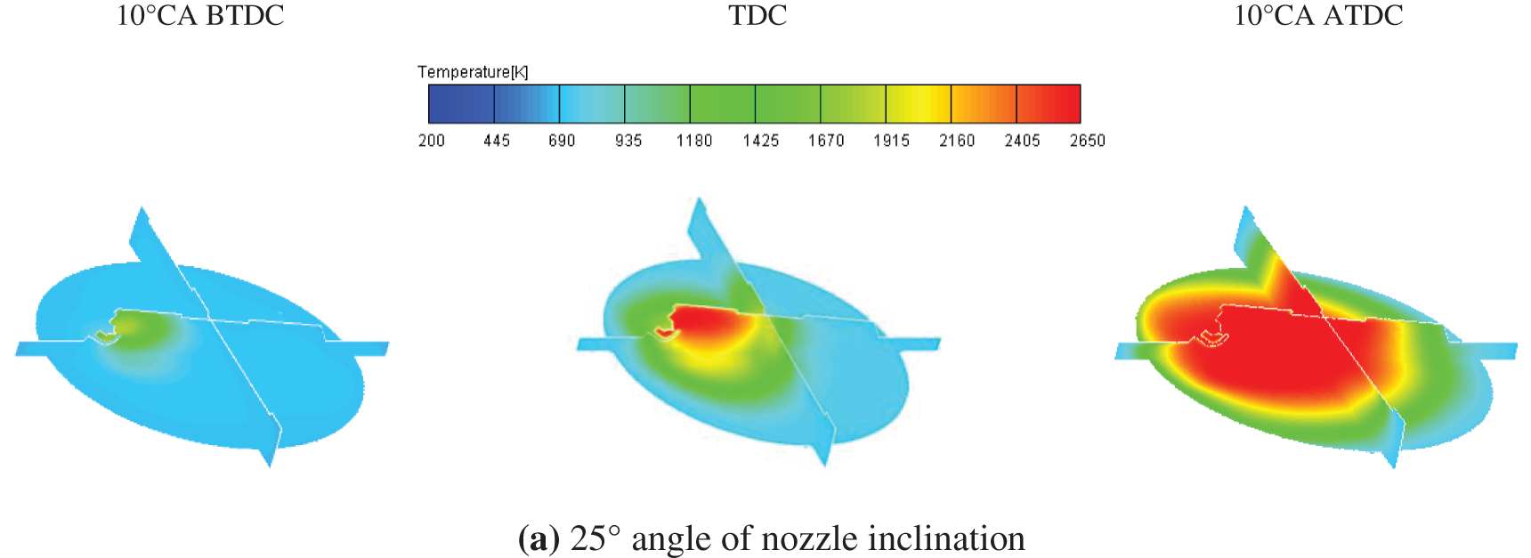
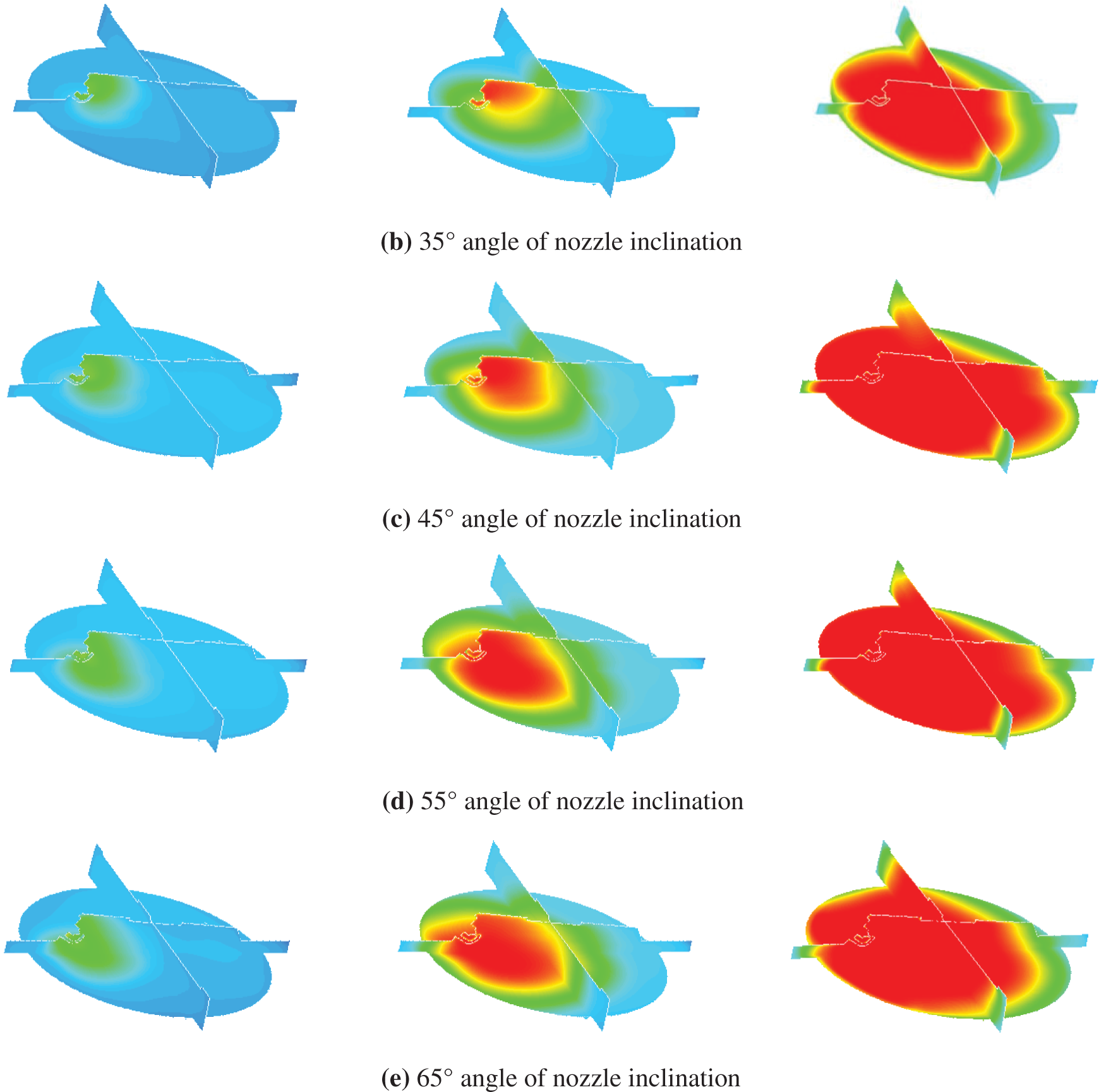
Figure 13: Temperature distribution in the cylinder at different angles of nozzle inclination
In summary, when the angle of nozzle inclination is 35°–55°, the engine combustion performance is good under the guarantee of good fuel‐air mixing in the cylinder.
The influence of the angle of nozzle inclination on aviation heavy fuel piston engines was studied using AVL FIRE, focusing on the influence of different angles of nozzle inclination on fuel-air mixing characteristics and combustion characteristics to promote fuel-air mixing and improve combustion quality. The following conclusions are obtained through experiment and simulation:
(1) With an increase in the angle of nozzle inclination, the turbulent kinetic energy in the combustion chamber increases continuously before and after ignition. This aids in improving the formation quality of the mixture in the cylinder, accelerates the propagation of the flame, and improves combustion efficiency. However, when the angle of nozzle inclination is greater than 45°, the unevenness of the fuel-air mixture increases and the area of high turbulence decreases. This situation is not conducive to accelerating the combustion heat release rate. When the angle of nozzle inclination is 45°, the fuel spray has the best compatibility with the combustion chamber geometry and the airflow. The fuel evaporation in the cylinder is the best, the fuel droplets completely evaporate before the ignition timing, and there is no high fuel accumulation area in the cylinder. The process of fuel-air mixing is accelerated, and the quality of the mixture is better.
(2) With an increase in the angle of nozzle inclination, the maximum combustion pressure in the cylinder first increases and then decreases. When the angle of nozzle inclination increases to 45°, the combustion condition in the cylinder is not improved by increasing the angle of nozzle inclination. At this time, a relatively regular flow in the cylinder is formed, which is conducive to the spread of the flame. The combustion process is well organized, the in-cylinder temperature rises quickly, the peak heat release rate increases by 20%, and the combustion explosion pressure increases by 5.5%. When the angle of nozzle inclination continues to increase, the time of fuel spray hitting the wall is advanced because the angle of nozzle inclination is too large. As a result, the mixing time of fuel spray and evaporation in the cylinder is shortened, and an accumulation forms on the wall surface, resulting in insufficient combustion heat release.
(3) When the angle of nozzle inclination is 35°–55°, the fuel-air mixing performance in the cylinder is better, and the engine combustion performance is good.
Acknowledgement: Thanks to Jian Meng, the corresponding author of the article.
Funding Statement: The authors received no specific funding for this study.
Author Contributions: Study conception and design: Jian Meng; Data collection: Peidong Zhao, Wenke Xu; Analysis and interpretation of results: Zhigang Wang, Baoli Wang, Fanyan Meng; Draft manuscript preparation: Zhigang Wang; Supervision: Bin Zheng. All authors reviewed the results and approved the final version of the manuscript.
Availability of Data and Materials: The data underlying this article will be shared on reasonable request to the corresponding author.
Conflicts of Interest: The authors declare that they have no conflicts of interest to report regarding the present study.
References
1. Gotthard, T., Beyfuss, B., Hofmann, P. (2022). Comparison of different fuel operations of a multi-fuel single-disk rotary engine through thermodynamic analysis. SAE Technical Paper, 2022-01-5032. [Google Scholar]
2. Yu, C., Zhao, Z., Wang, L., Cui, H., Zhang, F. (2020). The effect of cooled EGR on combustion and load extension in a kerosene spark-ignition engine. Fuel, 280(4), 118681. [Google Scholar]
3. Beyfuss, B., Flicker, L., Gotthard, T., Hofmann, P., Zahradnik, F. et al. (2021). Evaluation of spark-ignited kerosene operation in a wankel rotary engine. SAE Technical Paper, 2021-01-5046. [Google Scholar]
4. Cui, H., Zhao, Z., Zhang, F., Yu, C., Wang, L. (2021). Effect of pre-chamber volume on combustion characteristics of an SI aircraft piston engine fueled with RP3. Fuel, 286(1), 119238. [Google Scholar]
5. Bayındır, H., Işık, M. Z., Aydın, H. (2017). Evaluation of combustion, performance and emission indicators of canola oil-kerosene blends in a power generator diesel engine. Applied Thermal Engineering, 114(5), 234–244. [Google Scholar]
6. Ning, L., Duan, Q., Wei, Y., Zhang, X., Yu, K. et al. (2019). Effects of injection timing and compression ratio on the combustion performance and emissions of a two-stroke DISI engine fuelled with aviation kerosene. Applied Thermal Engineering, 161, 114124. [Google Scholar]
7. Donnelly, J., Horton, R., Gopalan, K., Bannister, C. D., Chuck, C. J. (2016). Branched ketone biofuels as blending agents for Jet-A1 aviation kerosene. Energy & Fuels, 30(1), 294–301. [Google Scholar]
8. Wang, L., Zhao, Z., Yu, C., Cui, H. (2022). Experimental study of aviation kerosene engine with PJI system. Energy, 248(1), 123590. [Google Scholar]
9. Zhou, Y., Li, X., Ding, S., Zhao, S., Zhu, K. et al. (2022). Technologies and studies of gas exchange in two-stroke aviation piston engine: A review. Chinese Journal of Aeronautics, 32(2), 489. [Google Scholar]
10. Lu, Y., Pan, J., Fan, B., Otchere, P., Chen, W. et al. (2019). Research on the application of aviation kerosene in a direct injection rotary engine–Part 1: Fundamental spray characteristics and optimized injection strategies. Energy Conversion and Management, 195(9), 519–532. [Google Scholar]
11. Pan, K., Wallace, J. (2021). Computational studies of fuel injection strategies on natural gas combustion characteristics in direct-injection engines. Fuel, 288(6), 119823. [Google Scholar]
12. Sharma, V., Eswaran, V., Chakraborty, D. (2020). Effect of fuel-jet injection angle variation on the overall performance of a SCRAMJET engine. Aerospace Science and Technology, 100(8), 105786. [Google Scholar]
13. Armin, M., Gholinia, M., Pourfallah, M., Ranjbar, A. A. (2021). Investigation of the fuel injection angle/time on combustion, energy, and emissions of a heavy-duty dual-fuel diesel engine with reactivity control compression ignition mode. Energy Reports, 7(2), 5239–5247. [Google Scholar]
14. Mano Alexander, P., Nandhakumar, S., Seenivasan, S., Ashfaq Ahamed, N. A., Raj Kumar, P. (2021). Optimal orientation of injectors for efficient spray pattern of fuel flow in a diesel engine. Materials Today: Proceedings, 37, 2890–2896. [Google Scholar]
15. Payri, R., Salvador, F. J., de la Morena, J., Pagano, V. (2018). Experimental investigation of the effect of orifices inclination angle in multihole diesel injector nozzles. Part 2–Spray characteristics. Fuel, 213(D1), 215–221. [Google Scholar]
16. Ji, C., Chang, K., Wang, S., Yang, J., Wang, D. et al. (2021). Effect of injection strategy on the mixture formation and combustion process in a gasoline direct injection rotary engine. Fuel, 304(5), 121428. [Google Scholar]
17. Farajollahi, A. H., Firuzi, R., Rostami, M., Mardani, A. (2022). Numerical study on the effects of creating rotationary flow inside the injector nozzle and changing fuel injection angle on the performance and emission of caterpillar diesel engine. Journal of the Brazilian Society of Mechanical Sciences and Engineering, 44(1), 3. [Google Scholar]
18. Cong, D. N., Duc, K. N. (2022). Numerical investigation into the effects of fuel injection parameters and piston bowl geometry on exhaust pollutants and performance of diesel engine. Advances in Engineering Research and Application: Proceedings of the International Conference on Engineering Research and Applications, pp. 739–751. Cairo, Egypt. [Google Scholar]
19. Renald, C. J. T., Somasundaram, P. (2012). Experimental investigation on attenuation of emission with optimized LPG jet induction in a dual fuel diesel engine and prediction by ANN model. Energy Procedia, 14, 1427–1438. [Google Scholar]
20. Li, X., Cheng, Y., Ma, X., Yang, X. (2019). The sensitivity of inner nozzle flow in gasoline direct injection injector to the nozzle geometry parameters. Journal of Engineering for Gas Turbines and Power, 141(6), 061017. [Google Scholar]
21. Khan, S., Panua, R., Bose, P. K. (2018). Combined effects of piston bowl geometry and spray pattern on mixing, combustion and emissions of a diesel engine: A numerical approach. Fuel, 225, 203–217. [Google Scholar]
22. Zareei, J. A. V. A. D., Haseeb, M., Ghadamkheir, K., Farkhondeh, S. A., Yazdani, A. et al. (2020). The effect of hydrogen addition to compressed natural gas on performance and emissions of a DI diesel engine by a numerical study. International Journal of Hydrogen Energy, 45(58), 34241–34253. [Google Scholar]
23. Song, E., Liu, Z., Yang, L., Yao, C., Sun, J. et al. (2017). Effects of nozzle structure on the gas mixture uniformity of marine gas engine. Ocean Engineering, 142(7), 507–520. [Google Scholar]
24. Krishna, B. M., Mallikarjuna, J. M. (2012). Characterization of flow through the intake valve of a single cylinder engine using particle image velocimetry. Journal of Applied Fluid Mechanics, 3(2), 23–32. [Google Scholar]
25. Fire, A. (2017). CFD User Manual. http://www.avl.com/en [Google Scholar]
26. Huethorst, J. A. M., Marra, J. (1991). Motion of marangoni-contracted water drops across inclined hydrophilic surfaces. Langmuir, 7(11), 2756–2763. [Google Scholar]
27. Huh, K. Y. (1991). A phenomenological model of diesel spray atomisation. Proceedings of the International Conference on Multiphase Flows, Tsukuba, Japan. [Google Scholar]
28. Durbin, P. A. (1991). Near-wall turbulence closure modeling without “damping functions”. Theoretical and Computational Fluid Dynamics, 3(1), 1–13. [Google Scholar]
29. Asadi, A., Zhang, Y., Mohammadi, H., Khorand, H., Rui, Z. et al. (2019). Combustion and emission characteristics of biomass derived biofuel, premixed in a diesel engine: A CFD study. Renewable Energy, 138(10), 79–89. [Google Scholar]
30. Azad, A. K., Halder, P., Nanthagopal, K., Ashok, B. (2019). Investigation of diesel engine in cylinder flow phenomena using CFD cold flow simulation. In: Advanced biofuels, pp. 329–336. Cambridgeshire, UK: Woodhead Publishing. [Google Scholar]
31. Launder, B. E., Spalding, D. B. (1983). The numerical computation of turbulent flows. In: Numerical prediction of flow, heat transfer, turbulence and combustion, pp. 96–116. Oxford, UK: Pergamon Press. [Google Scholar]
32. Khan, S., Panua, R., Bose, P. K. (2019). The impact of combustion chamber configuration on combustion and emissions of a single cylinder diesel engine fuelled with soybean methyl ester blends with diesel. Renewable Energy, 143, 335–351. [Google Scholar]
33. O’Rourke, P. J. (1981). Collective drop effects on vaporizing liquid sprays (Doctoral Dissertation). Princeton University, USA. [Google Scholar]
34. Han, X. (2022). Analysis and improvement of combustion system in a spark ignition aviation kerosene direct injection engine (Master Thesis). Shandong University of Technology, China. [Google Scholar]
35. Kim, D., Shin, J., Son, Y., Park, S. (2021). Characteristics of in-cylinder flow and mixture formation in a high-pressure spray-guided gasoline direct-injection optically accessible engine using PIV measurements and CFD. Energy Conversion and Management, 248(3), 114819. [Google Scholar]
36. Li, Y., Nithyanandan, K., Meng, X., Lee, T. H., Li, Y. et al. (2017). Experimental study on combustion and emission performance of a spark-ignition engine fueled with water containing acetone-gasoline blends. Fuel, 210, 133–144. [Google Scholar]
Cite This Article
 Copyright © 2024 The Author(s). Published by Tech Science Press.
This work is licensed under a Creative Commons Attribution 4.0 International License , which permits unrestricted use, distribution, and reproduction in any medium, provided the original work is properly cited.
 Downloads
 Citation Tools