
 Submit a Paper
 Propose a Special lssue
 Open Access
ARTICLE

Numerical Study on the Effect of Vortex Generators on the Aerodynamic Drag of a High-Speed Train
1 State Key Laboratory of Rail Transit Vehicle System, Southwest Jiaotong University, Chengdu, 610031, China
2 School of Design, Southwest Jiaotong University, Chengdu, 610031, China
* Corresponding Author: Tian Li. Email:
Fluid Dynamics & Materials Processing 2024, 20(2), 463-473. https://doi.org/10.32604/fdmp.2023.043618
Received 07 July 2023; Accepted 30 October 2023; Issue published 14 December 2023
 View Full Text
 Download PDF
Abstract
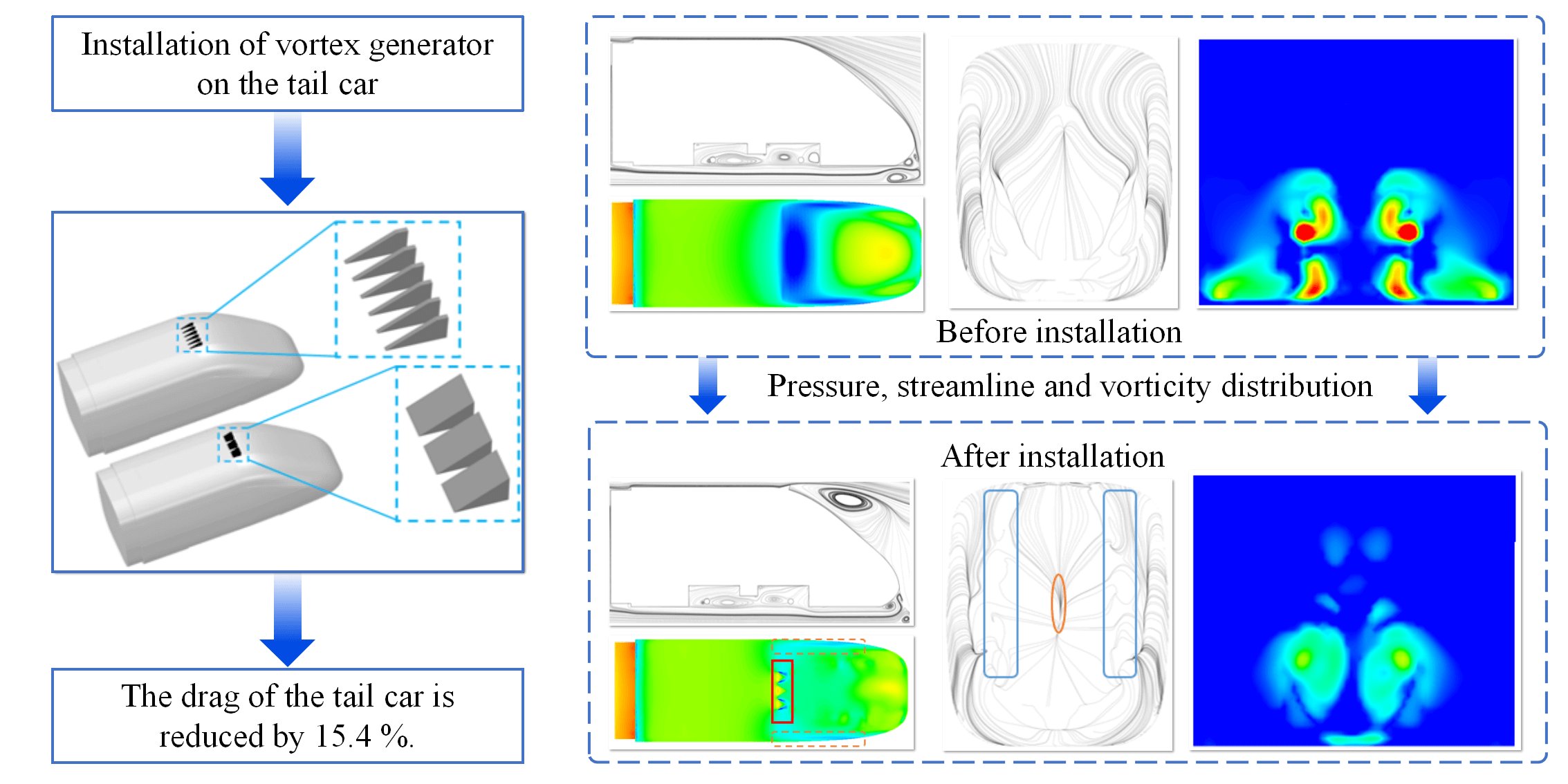
A relatively high aerodynamic drag is an important factor that hinders the further acceleration of high-speed trains. Using the shear stress transport (SST) k-ω turbulence model, the effect of various vortex generator types on the aerodynamic characteristics of an ICE2 (Inter-city Electricity) train has been investigated. The results indicate that the vortex generators with wider triangle, trapezoid, and micro-ramp arranged on the surface of the tail car can significantly change the distribution of surface pressure and affect the vorticity intensity in the wake. This alteration effectively reduces the resistance of the tail car. Meanwhile, the micro-ramp vortex generator with its convergent structure at the rear exhibits enhanced flow-guiding capabilities, resulting in a 15.4% reduction in the drag of the tail car.Graphic Abstract
Keywords
With the advantage of safety, comfort, swiftness, and low energy-consumption, high-speed trains emerge as the optimal preference for travelers seeking a superior mode of transportation [1,2]. As the velocity of high-speed trains escalates, the air resistance they encounter grows in direct proportion to the square of their velocity, while the energy consumption of the trains maintains a positive correlation with the cube of their velocity [3,4]. Consequently, air resistance remains a pivotal constraint on the advancement of high-speed train speeds.
Up to now, many researchers have predominantly engaged in studies targeting the reduction of aerodynamic drag in high-speed trains. The conventional approach to optimize the aerodynamic drag force of high-speed trains mainly focuses on the head shape design [5,6], the underneath structures of the train body [7,8], the inter-car region of the train [9,10], and pantograph [11]. However, the scope for implementing traditional aerodynamic drag optimizations is confined, and these drag reduction techniques have seen incremental advancements, resulting in a progressively diminishing optimization space. Consequently, novel drag reduction technologies have gradually garnered the attention of researchers. The drag reduction technologies are mainly divided into active control technology and passive control technology. Active control technologies mainly include blowing and suction drag reduction [12,13], as well as plasma drag reduction [14]. While passive control technologies include biomimetic surface drag reduction and flow control drag reduction by means of vortex generators (VG). Presently, high-speed train drag reduction technology based on vortex generators has gained significant traction as a focal point for researchers. By installing smaller devices on the train body to change the wake, the energy consumption of train operation is reduced.
In 1947, Taylor [15] first proposed the concept of the vortex generator and applied it to aviation, automobiles and so on, which can effectively achieve flow separation on wings and aerodynamic drag reduction on cars. Özden et al. [16,17] studied the S809 airfoil by using flap and vortex generators as integral components. Meanwhile, the application of single and double VGs was studied, and the results provide a theoretical basis for a deeper understanding of the mechanism of vortex generators. Evrard et al. [18] conducted a comparative study on the effect of vortex generators on the Ahmed and Peugeot 208 real car bodies by means of wind tunnel tests. The study showed the beneficial effect of vortex generators on the base resistance, and the magnitude of the effect depends on the type of vortex generator. Aziz et al. [19] verified the flow control effect of vortex generators on a simplified eight-carriage high-speed train from the aspects of the configuration, size, and direction of the vortex generator. It is pointed out that the co-rotating VGs have a better drag reduction effect. Du et al. [20] conducted transient numerical simulations of the CRH5 train with VGs arranged, and the results show that the surface flow and aerodynamic drag of the train are affected by the position of the VGs. Li et al. [21] selected the ICE2 train as the research object. From the perspective of flow control, it is discussed that the arrangement of vortex generators at the flow separation point can affect the surface pressure of the tail car and thus achieve drag reduction.
Based on the previous study [21], it is found that a reasonable arrangement of the vortex generator at the tail of the ICE2 train can achieve a better drag reduction effect. In addition, the type of vortex generator is also one of the key factors. When different types of vortex generators were installed on the train, they may show completely different characteristics. Therefore, based on the fact that the triangular and trapezoidal vortex generators have been used in the automotive field for many years, this study investigated the effects of different types of vortex generators on the aerodynamic characteristics of ICE2 trains from the perspectives of pressure, flow field structure and resistance. The results probe the drag-reduction potential of high-speed trains using vortex generators.
2 Governing Equation, Numerical Information
The flow field around a train running in the open air with a speed of 200 km/h can be considered as a three-dimensional incompressible viscous turbulent flow. The mass and momentum equations are as follows:
where
Meanwhile, SST k-ω model is used in this study. The method combines the advantages of standard k-ω turbulence model in near-wall calculation and k-ε turbulence model in far-field calculation, and is widely used in the high-speed train aerodynamics [22,23]. The corresponding equations are as follows [24]:
where k is turbulent kinetic energy; ω is the turbulent specific dissipation rate;
The 1/10th scaled model of the ICE2 train is taken as the research object, as shown in Fig. 1. The tail car includes only the streamlined part of the train and a bogie. The train model used in this study is consistent with the model used in previous studies [21]. The three-dimensional size of the train is 3.552 m × 0.302 m × 0.358 m.
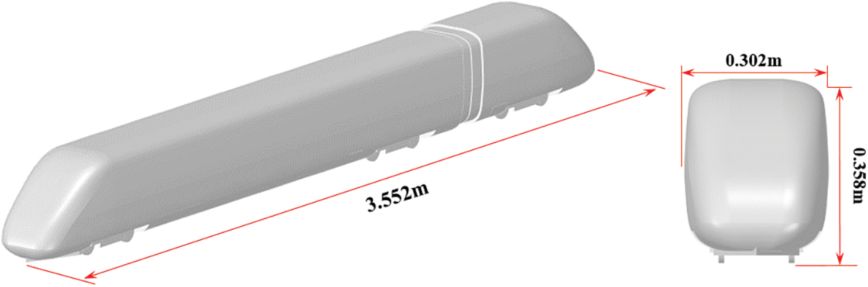
Figure 1: Train model
2.3 Different Types of Vortex Generator Models
Since the inception of vortex generators, many scholars have undertaken thorough and comprehensive investigations into their applications. Especially, the type of vortex generators is one of the most extensively explored aspects [25,26]. Diverse types of vortex generators yield wholly distinct impacts on identical components. Fig. 2 shows the common type of traditional vortex generators.
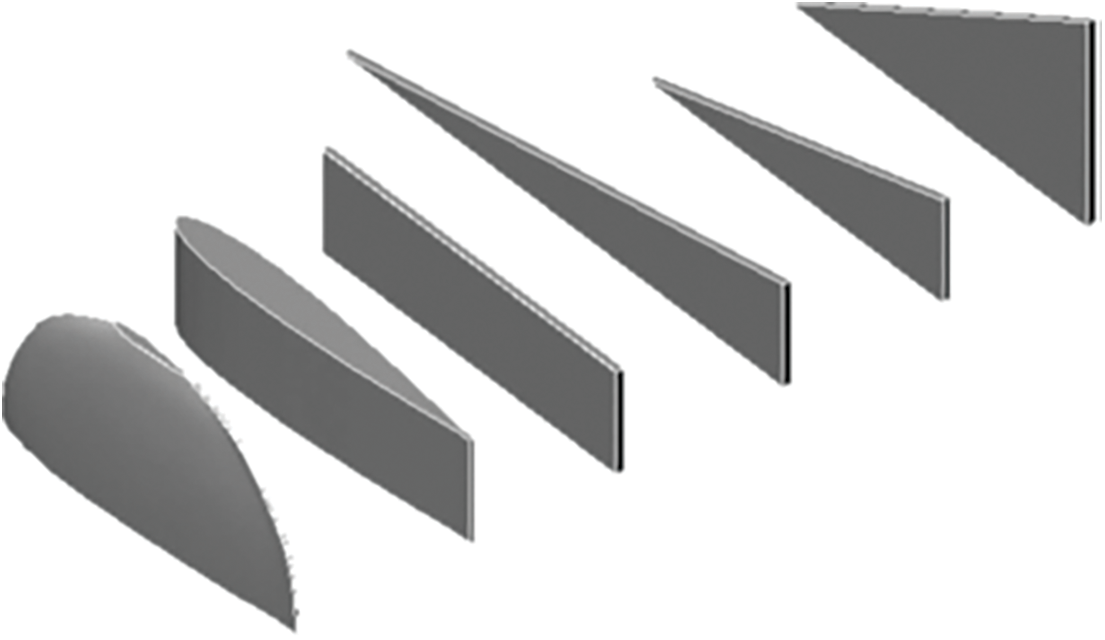
Figure 2: Several common types of vortex generators
According to our previous research, we obtained the optimal installation location of vortex generator based on ICE2 train. Therefore, this article is based on the study of the impact of vortex generator types on aerodynamic drag reduction of ICE2 trains, and selects the optimal layout position of the vortex generator obtained above. The positions of the different types of VGs correspond to the optimal positions of the VGs obtained [21], and the shape parameters of vortex generators refer to the previous research [25]. Fig. 3 shows the schematic diagrams of triangle and trapezoid vortex generators. The β of the triangle and trapezoid vortex generators is 30°, and the height H is 15 mm, consistent with those of the micro-ramp vortex generator. The upper base of the trapezoid vortex generator is 10 mm. According to the study by Heyes et al. [26], vortex generators with small aspect ratios may perform better in flow control. Therefore, the widths of the triangle and trapezoid vortex generators are 4 and 30 mm, respectively, with a width of 30 mm. When the width W is 4 mm, 6 vortex generators are arranged on the top surface of the train. When the width W is 30 mm, 3 vortex generators are arranged.
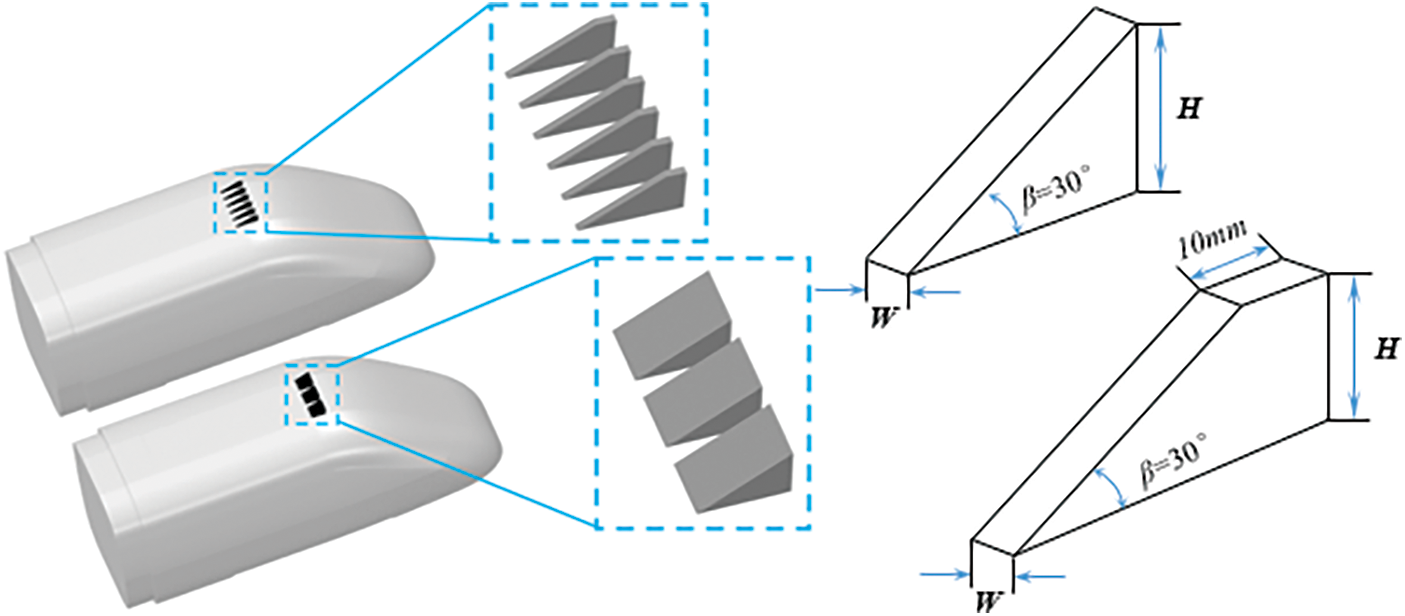
Figure 3: Triangle and trapezoid vortex generators
2.4 Computational Domain and Boundary Conditions
The computational domain of all cases is consistent. The three-dimensional size of the computational domain is 30 m × 6 m × 4 m, and the train is 0.0503 m from the ground, as shown in Fig. 4. The distance between the nose of the head car and the inlet is 10 m, which satisfied the requirements in computational domain.
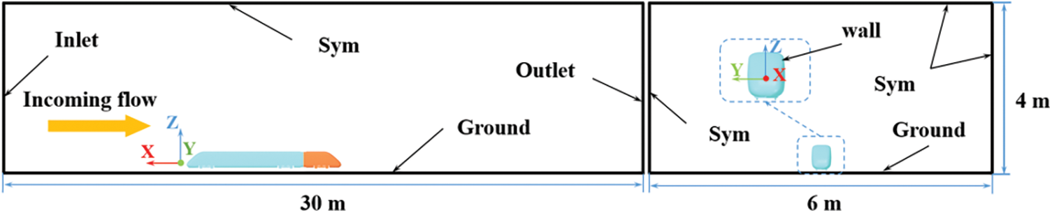
Figure 4: Computational domain
For the boundary conditions, the inlet is set to velocity inlet with a speed of 55.56 m/s, outlet is set to pressure outlet and its surface pressure is 0 Pa, the top and sides are set to symmetry planes, the train surface and ground are fixed wall boundaries. The air density is 1.225 kg/m3, and the kinematic viscosity is 1.7894 × 10⁻⁵ Pa∙s.
In the numerical simulation, a pressure-based solver is used. The SIMPLE (Semi Implicit Method for Pressure Linked Equations) algorithm is used to deal with the coupling between pressure and velocity, and the second-order upwind scheme is used to discretize all terms in the control equation.
Based on the published experimental and numerical simulation data, the validation of the calculation method is carried out in this paper, and the verification results can be found in [21].
2.6 Grid Generation and Grid Independent Test
To accurately capture the details of the flow field, the discrete grid must be refined. As shown in Fig. 5, the three refined regions are defined inside the computational domain, which represent the regions where the flow field changes dramatically and the physical quantity gradient is large. In addition, to solve the attached flow on the train surface, the boundary layer grid is also considered. The height of the first layer is 0.01 mm to meet the turbulence model’s demand for y+ less than 1, the growth rate is set to 1.2, and a total of 12 layers are divided to ensure that the boundary layer grid contains the entire viscous layer.
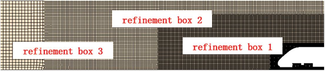
Figure 5: Computational grid
In order to ensure the effectiveness of the comparison, the dimensionless drag coefficient Cd and lift coefficient Cl were selected for comparison, which are defined as follows:
where Fd is the aerodynamic drag force, Fl is the aerodynamic lift force, ρ is the air density (1.225 kg/m3), U is the train’s running speed (55.56 m/s), and S is the cross-sectional area of the train.
The accuracy of numerical results is closely related to the grid number. Therefore, the grid independence test is carried out. For the same ICE2 train model, refinement box and computational domain, different grid sizes are selected, three sets of grids with different density are generated. The number of the three sets of grids is 13.72 million, 19.73 million and 28.43 million, respectively. As shown in Fig. 6, there is a significant difference between the aerodynamic force coefficients calculated using coarse grid and those obtained using medium or fine grids. For the other two sets of grids, the error is less than 1%. Therefore, the medium grid can be considered as the optimal choice and used in subsequent simulation cases.
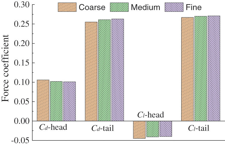
Figure 6: Computational results obtained using different grids
For trains with different types of vortex generators, the aerodynamic force and flow field structure are compared and analyzed.
3.1 Aerodynamic Forces of Trains
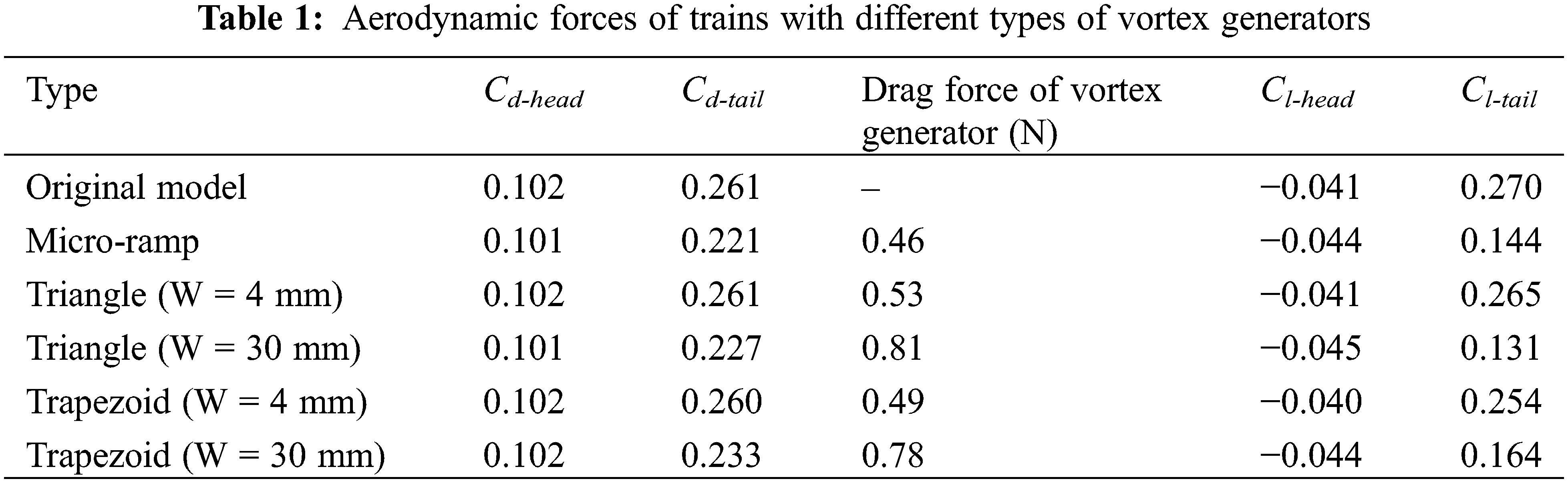
The aerodynamic results of all calculation cases are listed in Table 1. The aerodynamic drag of the head car is basically not affected by the vortex generator installed on the tail car, while the lift force changes slightly. The sensitivity of the train’s lift force to the grid is high, and differences in grid division are inevitable issues. The maximum difference in the lift force of the car with vortex generators compared to the original model is 8.89%. The lift force of the tail car with vortex generators varies significantly, with a change rate of 40% to 50%. Therefore, the change in lift of the head car is significantly within an acceptable range compared to that in drag of the head car. Meanwhile, the change of aerodynamic drag of the tail car is more significantly affected by different type of vortex generators. Triangle and trapezoid vortex generators with a width of 4 mm have almost no drag reduction effect. Whereas the triangle, trapezoid, and micro-ramp vortex generators with a width of 30 mm all show good drag reduction effects, with the drag reduction effect in descending order being micro-ramp, triangle, and trapezoid, among which the micro-ramp vortex generator reduces the drag force of the tail car by 15.4%. The drag force of the micro-ramp vortex generator itself is also the smallest among all types of vortex generators. The drag of the triangle and trapezoid vortex generators with a width of 30 mm is greater than that of the vortex generators with a width of 4 mm. Besides, the type of vortex generator also has a significant effect on reducing the lift force of the tail car. Triangle, trapezoid, and micro-ramp vortex generators with a width of 30 mm not only have good drag reduction effects, but also a more obvious reduction effect on the lift force of the tail car. The reduction effect on the lift force of the tail car is in descending order of triangle, micro-ramp, and trapezoid, among which the reduction effect on the lift of the tail car by the triangle vortex generator can be up to 51.4%.
The pressure comparison results of the tail car surface for all calculation cases are shown in Fig. 7. There are significant differences in pressure distribution. It can be observed that the pressure on the first row of tail cars is relatively consistent, the pressure distribution on the second row of tail cars is similar, and there is a significant difference in pressure distribution between the two rows. From the perspective of pressure distribution, the triangular and trapezoidal vortex generators with a width of W = 4 mm are installed on the tail car and do not cause significant changes, which also explains why the triangular and trapezoidal vortex generators with a width of W = 4 mm have almost no drag reduction effect on the tail car, as shown in Table 1. The pressure distribution of the tail cars with triangle, trapezoid, and micro-ramp vortex generators with a width of W = 30 mm is relatively consistent, and compared with the prototype’s pressure distribution of the tail cars, the negative pressure on the top and both sides of the tail cars is significantly reduced, which is the main reason for the reduction in aerodynamic drag and lift forces of the tail cars. By comparing the pressure on the red rectangle region in the figure, it can be seen that the negative pressure zone behind the micro-ramp vortex generator is the smallest, and that of the trapezoid vortex generator is the largest. By comparing the pressure distribution on both sides of the train in the orange dashed box, it can be seen that the negative pressure value on both sides of the tail car with the micro-ramp vortex generator is the smallest, and that of the trapezoid vortex generator is the largest.
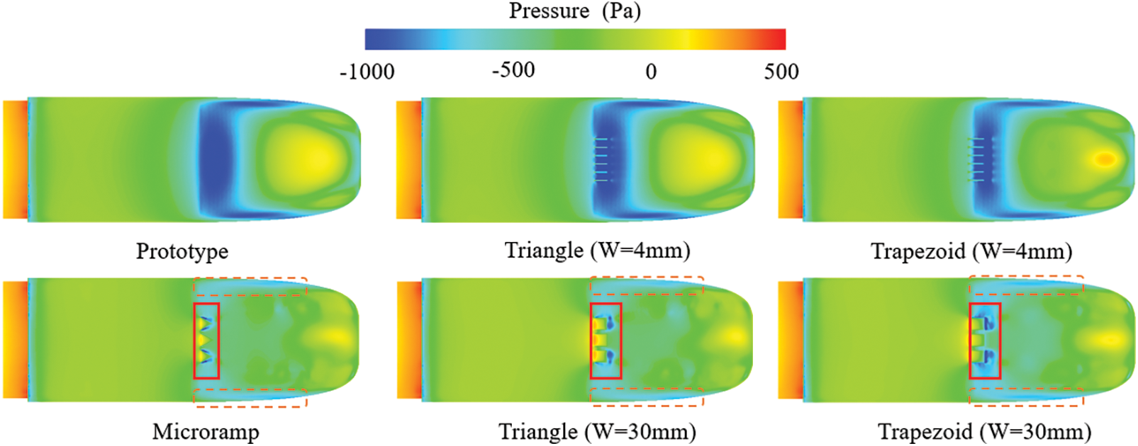
Figure 7: Pressure distribution on the tail car
Figs. 8 and 9 show the distribution of streamlines in space and on the surface. There are significant differences in the cross-section streamline distribution and surface pressure distribution for different types of vortex generators. Compared with the prototype train, the installation of a triangle vortex generator with a width of 4 mm on the tail car has little effect on the streamline distribution in the space. A large separation vortex appears in the tail car with a 4 mm width trapezoid vortex generator. The tail car with 30 mm width triangle, trapezoid, and micro-ramp vortex generators produces more obvious separation vortices. The chaotic streamlines in the blue rectangular box in Fig. 9 indicate that different types of vortex generators lead to significant differences in the surface streamlines. The orange oval box in the figure shows that the airflow reattaches to the train surface after leaving the vortex generator.
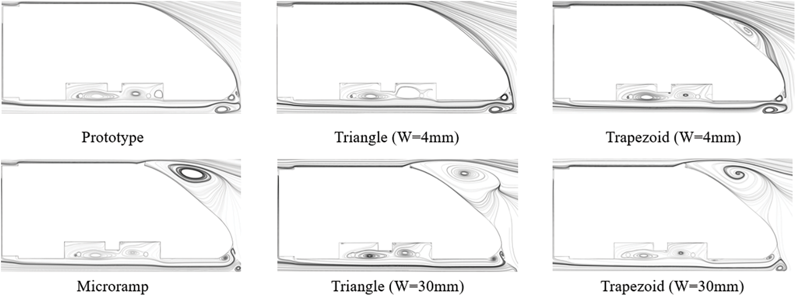
Figure 8: Distribution of cross-sectional streamlines around the tail car
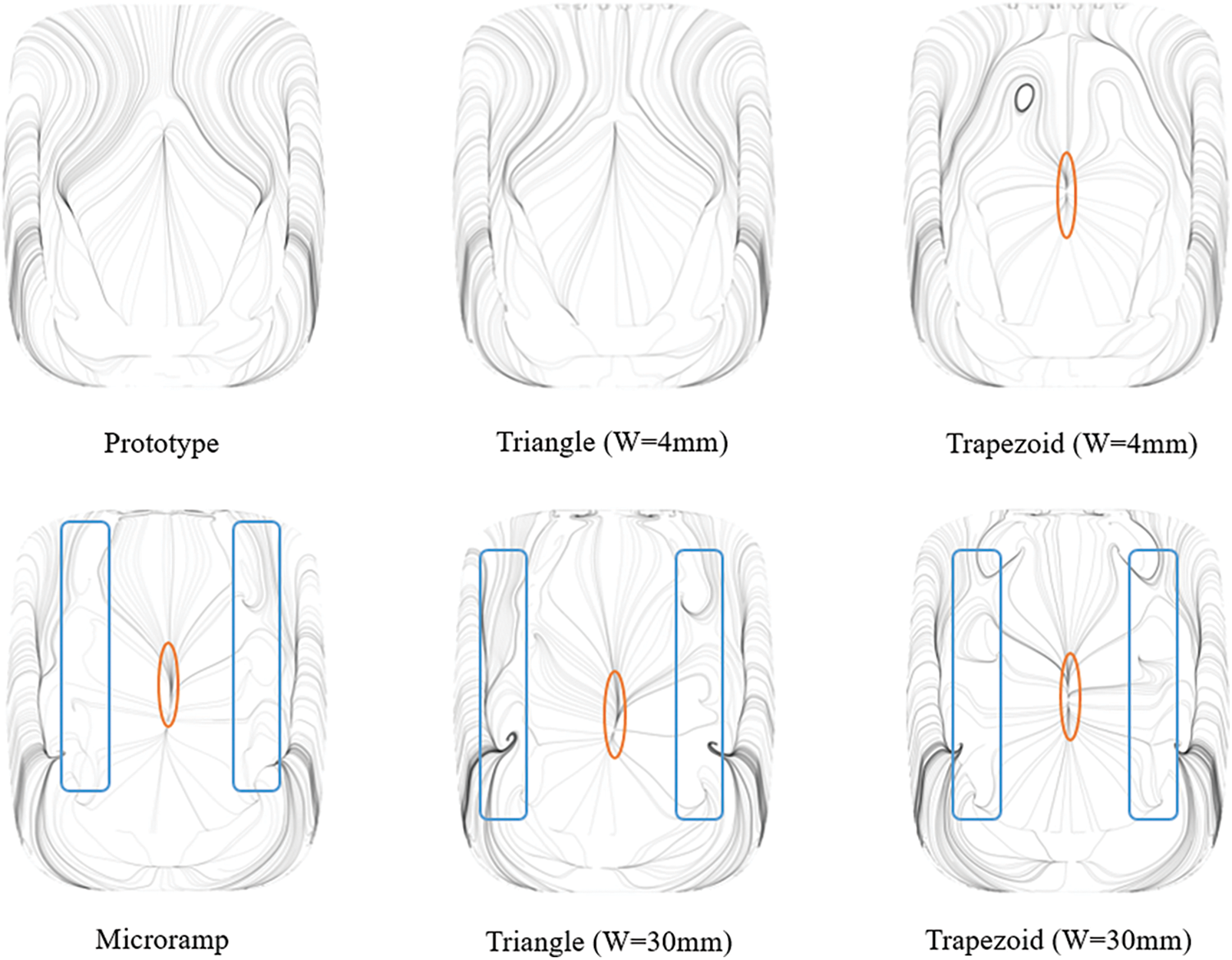
Figure 9: Streamline distribution on the tail car
Fig. 10 shows the vorticity distributions on the cross-section located at 42.5 mm far from the tail car nose tip. The type of vortex generator has a significant impact on the vorticity distribution in the wake. For the triangle vortex generator with a width of 4 mm, the vorticity amplitude distribution in the wake is similar to that of the prototype, while the trapezoid vortex generator with a width of 4 mm is reduced in both strength and lateral width. The vorticity distributions for the 30 mm width triangle, trapezoid, and micro-ramp vortex generators are significantly different from those of the prototype. Among them, the vorticity distributions for the triangular and micro-ramp vortex generators are relatively consistent in both strength and lateral width, while the vorticity distribution for the trapezoid vortex generator is slightly stronger. This also corresponds to the results shown in Table 1, which shows that the drag reduction effect of the trapezoid vortex generator is slightly worse among the 30 mm width vortex generators. This once again proves that the vortex generator triggers flow separation in advance, and the separation vortex behind it produces the drag reduction effect by breaking the spatial distribution of the original longitudinal development vortex and attenuating its strength.
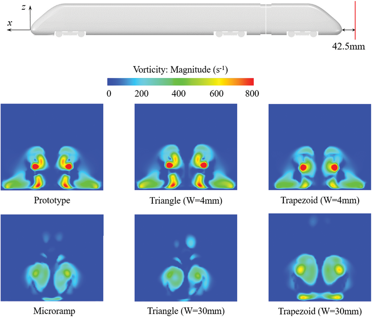
Figure 10: Vorticity diagram for different types of vortex generators
In summary, the installation of different types of vortex generators on the tail car will produce different drag reduction effects. The width of the vortex generator is a very important factor. The smaller width cannot achieve the purpose of drag reduction. On the contrary, the larger width can produce a significant drag reduction effect. This is because the larger width can change the flow separation and affect the surface pressure and wake. It is worth paying more attention to the micro-ramp vortex generator, which is due to the better diversion effect of the contraction structure on the airflow, resulting in more resistance reduction. Therefore, the micro-ramp vortex generator is the best among the common types of vortex generators in terms of drag reduction effectiveness.
(1) For all calculation cases, different types of vortex generators show different drag reduction effects. When the width of the vortex generator is small, it is difficult to change the flow field too much, resulting in almost no drag reduction effect. Wider triangle, trapezoid, and micro-ramp vortex generators can significantly destroy the airflow at the top of the prototype train, which affects the surface pressure and wake of the train, resulting in a reduction in the drag and lift of the tail car.
(2) The ranking of the drag reduction effects achieved by different types of vortex generators installed on the top of the ICE2 car is as follows. The best is the micro-ramp generator, followed by the triangle generator, and then the trapezoid generator. The triangle generator can achieve a drag reduction of 15.4% for the tail car.
(3) The vortex generator with a wider width installed on the tail car will trigger the flow separation earlier, resulting in a larger separation vortex in the wake. In addition, the vorticity amplitude in the wake also decreases significantly, which will reduce the resistance of the train.
Acknowledgement: The authors would like to thank Ms. Xiao Zhao for the design of cover image.
Funding Statement: This work supported by the National Natural Science Foundation of China (12372049), Sichuan Science and Technology Program (2023JDRC0062), Science and Technology Program of China National Accreditation Service for Conformity Assessment (2022CNAS15) and the Independent Project of State Key Laboratory of Rail Transit Vehicle System (2023TPL-T06).
Author Contributions: The authors confirm contribution to the paper as follows: study conception and design: Tian Li, Zerui Xiang; data collection: Hao Liang; analysis and interpretation of results: Hao Liang, Jiye Zhang; draft manuscript preparation: Tian Li. All authors reviewed the results and approved the final version of the manuscript.
Availability of Data and Materials: The data presented in this study are available from the corresponding author, upon reasonable request. The data are not publicly available due to privacy.
Conflicts of Interest: The authors declare that they have no conflicts of interest to report regarding the present study.
References
1. Tian, H. Q. (2019). Review of research on high-speed railway aerodynamics in China. Transportation Safety and Environment, 1(1), 1–21. [Google Scholar]
2. Qi, Y. H., Zhou, L. (2020). The fuxing: The China standard EMU. Engineering, 6(3), 227–233. [Google Scholar]
3. Li, T., Dai, Z. Y., Yu, M. G., Zhang, W. H. (2021). Numerical investigation on the aerodynamic resistances of double-unit trains with different gap lengths. Engineering Applications of Computational Fluid Mechanics, 15(1), 549–560. [Google Scholar]
4. Raghunathan, R. S., Kim, H. D., Setoguchi, T. (2002). Aerodynamics of high-speed railway train. Progress in Aerospace sciences, 38(6–7), 469–514. [Google Scholar]
5. Zhang, L., Dai, Z. Y., Li, T., Zhang, J. Y. (2022). Multi-objective aerodynamic shape optimization of a streamlined high-speed train using kriging model. Journal of Zhejiang University-Science A, 23(3), 225–242. [Google Scholar]
6. He, Z., Liu, T. H., Liu, H. (2022). Improved particle swarm optimization algorithms for aerodynamic shape optimization of high-speed train. Advances in Engineering Software, 173, 103242. [Google Scholar]
7. Liu, W., Ji, Z. L., Guo, D. L., Yang, G. W., Zhou, G. W. et al. (2022). Effects of bottom deflectors on aerodynamic drag reduction of a high-speed train. Acta Mechanica Sinica, 38(5), 1–15. [Google Scholar]
8. Wang, J. B., Minelli, G., Dong, T. Y., He, K., Krajnovic, S. (2020). Impact of the bogies and cavities on the aerodynamic behaviour of a high-speed train. An IDDES study. Journal of Wind Engineering and Industrial Aerodynamics, 207, 104406. [Google Scholar]
9. Cheng, F., Xiong, X. H., Tang, M. Z., Li, X. B., Wang, X. R. (2022). Impact of the gap distance between two adjacent external windshields of a high-speed train on surrounding flow characteristics: An IDDES study. Engineering Applications of Computational Fluid Mechanics, 16(1), 724–745. [Google Scholar]
10. Ding, S. S., Li, Q., Tian, A. Q., Du, J., Liu, J. L. (2016). Aerodynamic design on high-speed trains. Acta Mechanica Sinica, 32(2), 215–232. [Google Scholar]
11. Lee, Y., Rho, J., Kim, K. H., Lee, D. H., Kwon, H. B. (2015). Experimental studies on the aerodynamic characteristics of a pantograph suitable for a high-speed train. Proceedings of the Institution of Mechanical Engineers, Part F: Journal of Rail and Rapid Transit, 229(2), 136–149. [Google Scholar]
12. Che, Z. X., Huang, S., Li, Z. W., Chen, Z. W. (2023). Aerodynamic drag reduction of high-speed maglev train based on air blowing/suction. Journal of Wind Engineering and Industrial Aerodynamics, 233, 105321. [Google Scholar]
13. Liang, X. F., Luo, Z. J., Li, X. B., Xiong, X. H., Zhang, X. (2022). Drag reduction of high-speed trains via low-density gas injection. AIP Advances, 12(6), 065115. [Google Scholar]
14. Lee, H. W., Kwon, H. B. (2014). Analysis of the effects of SD plasma on aerodynamic drag reduction of a high-speed train. Journal of Electrical Engineering and Technology, 9(5), 1712–1718. [Google Scholar]
15. Taylor, H. D. (1947). The elimination of diffuser separation by vortex generators. Connecticut: United Aircraft Corporation. [Google Scholar]
16. Özden, M., Genc, M. S., Koca, K. (2023). Passive flow control application using single and double vortex generator on S809 wind turbine airfoil. Energies, 16(14), 5339. [Google Scholar]
17. Özden, M., Genc, M. S., Koca, K. (2023). Investigation of the effect of hidden vortex generator-flap integrated mechanism revealed in low velocities on wind turbine blade flow. Energy Conversion and Management, 287, 117107. [Google Scholar]
18. Evrard, A., Cadot, O., Sicot, C., Herbet, V., Ricot, D. et al. (2017). Comparative effects of vortex generators on Ahmed’s squareback and minivan car models. Proceedings of the Institution of Mechanical Engineers, Part D: Journal of Automobile Engineering, 231(9), 1287–1293. [Google Scholar]
19. Aziz, A., Zhang, Y., Gang, C. (2021). Computational studies of passive vortex generators for flow control on high-speed train. Civil Infrastructures Confronting Severe Weathers and Climate Changes Conference, pp. 95–108. Cham, Springer. [Google Scholar]
20. Du, H., Zhou, D., Meng, S., Luo, C. Y. (2022). Effect of vortex generators on the aerodynamic performance of high-speed trains. Flow, Turbulence and Combustion, 109(3), 627–645. [Google Scholar]
21. Li, T., Liang, H., Zhang, J., Zhang, J. Y. (2023). Numerical study on aerodynamic resistance reduction of high-speed train using vortex generator. Engineering Applications of Computational Fluid Mechanics, 17(1), e2153925. [Google Scholar]
22. Shankar, G., Devaradjane, G., Sunil, S. (2019). Investigation on aerodynamic behaviour of a SUV car model with vortex generators at different yaw conditions. Journal of Applied Fluid Mechanics, 12(1), 103–117. [Google Scholar]
23. Li, T., Qin, D., Zhang, J. Y. (2019). Effect of RANS turbulence model on aerodynamic behavior of trains in crosswind. Chinese Journal of Mechanical Engineering, 32(1), 85. [Google Scholar]
24. Menter, F. R. (1994). Two-equation eddy-viscosity turbulence models for engineering applications. AIAA Journal, 32(8), 1598–1605. [Google Scholar]
25. Verma, S. B., Manisankar, C. (2017). Assessment of various low-profile mechanical vortex generators in controlling a shock induced separation. AIAA Journal, 55(7), 2228–2240. [Google Scholar]
26. Heyes, A. L., Smith, D. A. R. (2005). Modification of a wing tip vortex by vortex generators. Aerospace Science and Technology, 9(6), 469–475. [Google Scholar]
Cite This Article
 Copyright © 2024 The Author(s). Published by Tech Science Press.
This work is licensed under a Creative Commons Attribution 4.0 International License , which permits unrestricted use, distribution, and reproduction in any medium, provided the original work is properly cited.
 Downloads
 Citation Tools