
 Submit a Paper
 Propose a Special lssue
 Open Access
ARTICLE

Coupled Numerical Simulation of Electromagnetic and Flow Fields in a Magnetohydrodynamic Induction Pump
1 College of Transportation, Ludong University, Yantai, 264025, China
2 College of Intelligent Manufacturing, City College of Huizhou, Huizhou, 516025, China
* Corresponding Author: He Wang. Email:
Fluid Dynamics & Materials Processing 2024, 20(4), 889-899. https://doi.org/10.32604/fdmp.2023.042728
Received 09 June 2023; Accepted 26 October 2023; Issue published 28 March 2024
 View Full Text
 Download PDF
Abstract
Magnetohydrodynamic (MHD) induction pumps are contactless pumps able to withstand harsh environments. The rate of fluid flow through the pump directly affects the efficiency and stability of the device. To explore the influence of induction pump settings on the related delivery speed, in this study, a numerical model for coupled electromagnetic and flow field effects is introduced and used to simulate liquid metal lithium flow in the induction pump. The effects of current intensity, frequency, coil turns and coil winding size on the velocity of the working fluid are analyzed. It is shown that the first three parameters have a significant impact, while changes in the coil turns have a negligible influence. The maximum increase in working fluid velocity within the pump for the parameter combination investigated in this paper is approximately 618%. As the frequency is increased from 20 to 60 Hz, the maximum increase in the mean flow rate of the working fluid is approximately 241%. These research findings are intended to support the design and optimization of these devices.Keywords
A magnetic fluid [1–3] is a liquid containing ultrafine magnetic particles, which not only possesses the magnetism of a solid magnetic material but can also flow like a liquid. Magnetic fluids have a wide range of application values due to their inherent characteristics. Currently, the efficient transport of magnetic fluids has become the key limiting factor in the application of such materials [4–6]. The magnetic fluid induction pump is a non-contact pump that operates on magnetic fluid technology, utilizing the Lorentz force generated by the current and the magnetic field within the liquid metal to induce its flow. In comparison with mechanical centrifugal pumps, this design eliminates the need for mechanical rotational components [7,8], thereby mitigating impeller corrosion concerns and significantly enhancing reliability [9–11]. Electromagnetic pumping offers several advantages, including a straightforward design, dependable operation, and minimal noise, among others. These pumps are capable of functioning effectively in demanding conditions, such as high temperature, high pressure, and corrosive environments, as encountered in the nuclear energy industry. The body part of the engine is usually made of stainless steel or titanium alloy, as its surface is expected to have good corrosion resistance properties [12]. Magneto hydrodynamic (MHD) induction pumps are frequently used in nuclear reactor cooling systems, as the induction pump can improve reactor safety due to its high level of airtightness [13]. Following the process of design optimization, the magnetic fluid induction pump has been effectively utilized in various domains, including chemical engineering, power, and nanometal fluid transportation [14]. This has resulted in significant advancements and practical implications, thereby making the attainment of improved structural parameters a prominent subject of interest within the industry. Haim [15] formulated the control equation for electrolyte MHD flow and investigated the phenomenon and application of MHD in microfluidic systems, such as the use of MHD to pump and stir fluids and to control the flow of fluids without any mechanical components. Kim et al. [16,17] set up a model based on Naser, discussed the relation between the exit pressure and the pump core length, as well as the inner core diameter, and then established the relationship between the flow rate and the outlet pressure as well as the inlet voltage and current. Following a discussion of the relationship between flow velocity and outlet pressure, the correlation was further modified to account for the frictional drag. We established the theory of magnetohydrodynamic analysis and then derived the mathematical model for the coupling of the electromagnetic Lorentz force and the fluid drag force. Wang et al. [18] proposed a theoretical model of electromagnetic pulse flow and pressure based on equivalent circuit theory, and parameters such as friction drag, local drag, and the effect of gravity were considered in the model. The difference between the calculated results of their theoretical model and their experimental results was close to ±40%, which was much smaller than the existing model. Roman et al. [19] modeled a fully coupled MHD flow in a circular linear induction pump. A three-dimensional numerical model of the synergistic effect of the electromagnetic and flow fields was constructed by Abdullina et al. [20], coupled with a turbulent fluid model, to investigate the characteristics of the flow during liquid metal transport in an annular induction pump. Araseki et al. [21] analyzed the MHD instability of the linear induction ring pump, compared the experimental and numerical results, and found that the fluid instability was suppressed. Boisson et al. [22] constructed a numerical model of a magnetofluid considering traveling waves and investigated the effect of traveling waves in MHD forced flow on the flow process of the working fluid in an induction pump. Gea et al. [23] used a numerical simulation to study the coreless design process of a large electromagnetic pump with two stirrers and verified the validity of the design solution. The CFD simulation approach taken by Shaker et al. [24] allowed for the investigation of the influence of inlet and outlet angles on the flow performance of ferrofluid magnetic micropumps. It was reported that increasing the pressure loss coefficient at sharp inlet and outlet angles could reduce the pump’s adaptability in the higher-pressure regime. A two-dimensional numerical model of a linear induction pump was constructed by Kirillov et al. [25] and the numerical results were compared with experimental results. The two pressures were found to be in good agreement, but the values of the power were somewhat different from the experimental values, thus, the model had some limitations and could not simulate the magnetic motion of the fluid caused by changes in the magnetic flux density and inflow angle. Ivanov et al. [26,27] set up the experimental induction pump platform and carried out the liquid-metal transport experiment, which completely demonstrated its feasibility.
In summary, while most studies have concentrated on the development of MHD models and the effect of temperature on pump performance, only a few researchers have conducted systematic research on the structure and operating parameters of the pump body. Based on such influencing factors as coil parameters, current strength and frequency, this paper constructs a numerical model of magnetohydrodynamics and analyzes the influence of relevant induction pump parameters on the transport speed of the liquid metal, explores the contribution of various factors to the delivery speed of induction pumps, and thereby lays the foundation for further optimization of induction pumps.
2 Object of Study and Theoretical Basis
The induction pump consisted of an electromagnetic coil, an isolation blanket, and an external protective cover. Due to the physical process of coupling the electromagnetic field and the flow field in a linear induction pump, it was difficult to fully describe this process using numerical methods. For this reason, this study selected local elements of the pump body as the research object and constructed a two-dimensional symmetric numerical model of the induction pump using the COMSOL [28,29] numerical simulation platform, as shown in Fig. 1. The calculation unit size was: h = 0.2 m, c = 0.066 m, l = 0.045 m; and the winding height and width of the coil were a and b, respectively, which were the parameters studied.
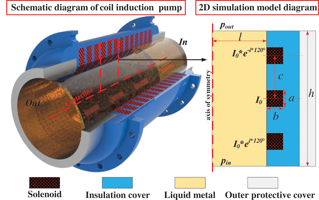
Figure 1: Structure diagram and two-dimensional calculation model of the induction pump
The working fluid in the induction pump was liquid metal lithium, which was transported under the action of Lorentz force, thus, the flow velocity in this process was relatively small. In addition, because the thermal effect generated by the coil being energized was overlooked, the working fluid in the pump could be regarded as an incompressible fluid. The control equation of magnetic fluid flow is as follows [30]:
Control equation of induced potential in solid wall area:
Magnetic induction intensity control equation:
In Eqs. (1)–(6), u is the velocity vector; J is the induced current density; B is the magnetic field vector; t is time; p is the fluid pressure; φ and φs are the induced potentials in the fluid and solid domains, respectively; ν is the fluid kinematic viscosity; ρ is the fluid density; σ and σs are the conductivities of the magnetic fluid and solid walls, respectively.
Given the initial average velocity U0 = 0 in the computational domain, the boundary condition of no slip was set at the wall, and the pressure difference between the workpiece outlet and the inlet was zero, that is, pin-pout = 0. Since the current was only present in the coil in the current structure, the potential at the inlet and outlet and the outer wall of the solid was zero, and their boundary conditions were ∂φ/∂n = 0 and ∂φs/∂n = 0, representing no current, where n represents the normal unit vector of the surface. In Fig. 1, the middle coil current is I0, the upper coil current is I0 * e−i*120°, the lower coil current is I0 * ei*120°, and the coil turns are N.
Since the solid wall is a conducting wall, it is necessary for the current and potential to satisfy coupled wall boundary conditions at the fluid-solid interface.
In fact, the temperature field has some impact on the electromagnetic medium. To simplify the numerical model, this study did not consider the influence of temperature changes on the electromagnetic parameters, and made the assumption that the liquid metal flow process was unaffected by the present skin effect thus simplifying the computational model and improving its steady-state performance. Fig. 2 presents the grid distribution and grid sensitivity validation. The results indicate that the outlet velocity values are similar for grid sizes of 12040 and 20228, with a grid increase of 98%. The variation in outlet velocity is approximately 0.3%. To enhance computational efficiency, this study simplifies the model into a two-dimensional numerical model comprising 12040 grid cells, with a minimum grid cell size of 1.3 mm.
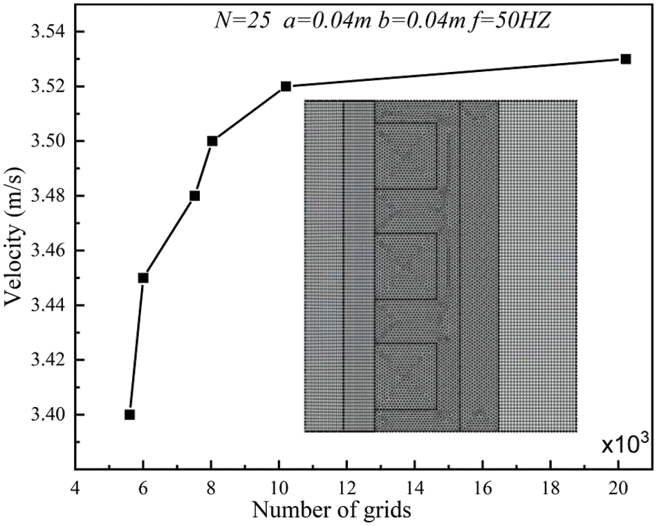
Figure 2: Grid distribution and grid sensitivity validation
Based on the theoretical foundations mentioned above, this study utilized COMSOL to conduct steady-state simulations on a two-dimensional research object. COMSOL is a platform that discretizes physics equations using the finite element method (FEM). During the solving process, a large-scale sparse matrix method (PARDISO), was employed.
To validate the rationality of the numerical model developed in this study, the magnetic fluid experimental structure described in reference [31] was chosen as the computational object. The pressure drop at the inlet and outlet under different Reynolds numbers (Re) was calculated, and the computed results were compared with the experimental results mentioned in the literature. As shown in Fig. 3, the results indicate close agreement between the numerical and experimental results, with errors falling within an acceptable range. Therefore, it can be concluded that the magnetic fluid numerical simulation constructed in this study is reasonable.
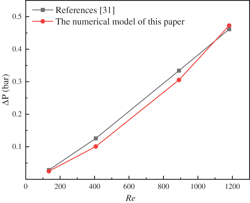
Figure 3: Numerical model validation
3.1 Distribution Characteristics of Magnetic Field and Flow Field
Fig. 4 shows the magnetic field and the velocity field under different parameters. Compared with the previously mentioned results, in terms of the magnetic field distribution, the maximum magnetic flux appeared on the wide edge of the upper and lower sides of the in-line coil winding. However, the value of the magnetic flux on the side close to the working medium should have been slightly greater than the value away from the working medium. Fundamentally, as the current settings and winding number change, the features of the magnetic flux distribution do not change, and there are differences only in the numerical values. In terms of the velocity field distribution, there was a clear effect of the boundary layer on the working medium close to the coil. At the same time, as the liquid metal of the induction pump was subjected to a combination of magnetic fields and flow fields, which were nonuniformly distributed across the computational domain, the liquid metal flow velocity near the fluid boundary layer also fluctuated as a function of the characteristics of the magnetic field distribution. Usually, this is more obvious if the current intensity and winding number are small, and the flow velocity in the circulating region of the working fluid will appear as the phenomenon of periodic variation of the equivalent region, which indicates that the internal velocity will also fluctuate in a periodic manner. However, as the current intensity was further increased, the periodic fluctuation was not obvious, and when the current intensity was low, the number of turns of the coil would obviously influence the distribution of these regions of equivalent velocity. From a practical standpoint, to improve the stability of the induction pump’s carrying capacity, this periodic fluctuation in velocity must be prevented. A common solution at present is to use higher coil turns and high current intensities, which serve to enhance the internal working fluid velocity and suppress the fluctuation in the flow field. The structural and working fluid parameters of the induction pump are thus of great importance for the stable transport of the working fluid. The influence of relevant parameters on the working fluid velocity are further discussed in the following subsections.
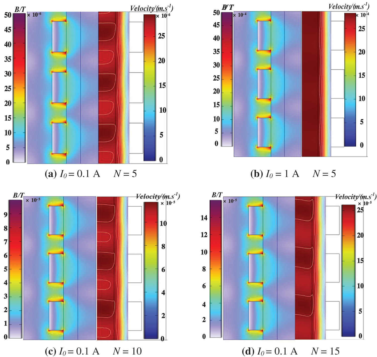
Figure 4: Magnetic field and velocity field under different parameters
3.2 Effect of Current Intensity on the Flow Rate of the Working Fluid
In practical engineering, current resistance is the main means of direct hardware control. Without affecting the stability of equipment, the current strength can be quickly increased to improve the efficiency of the equipment. From the results presented in Section 3.1, it was obvious that there were fluctuations in the liquid metal flow rate in the induction pump, with this fluctuation being less noticeable when the flow rate was high. The mean flow effect comparison index was adopted to facilitate comparison of the degree to which each parameter contributed to the flow field. In general, the larger the mean flow, the smaller the fluctuation in the flow field. Fig. 4 illustrates how the average working fluid velocity varied with current strength. It shows that increasing the current resistance did not have an obvious effect on increasing the flow velocity of the working fluid when the coil was rotating less. Although the flow rate of the working fluid was significantly affected by the current intensity when the coil turns were large, excessive current could easily have caused the coil temperature to increase. Therefore, it was necessary to avoid excessive current. As shown in Fig. 5, when there were 15 coil turns, the flow rate of the working fluid was close to linear with the current intensity. When the number of coil turns exceeded 15, increasing the current intensity led to a reduction in the rate of increase in the flow rate of the working fluid.
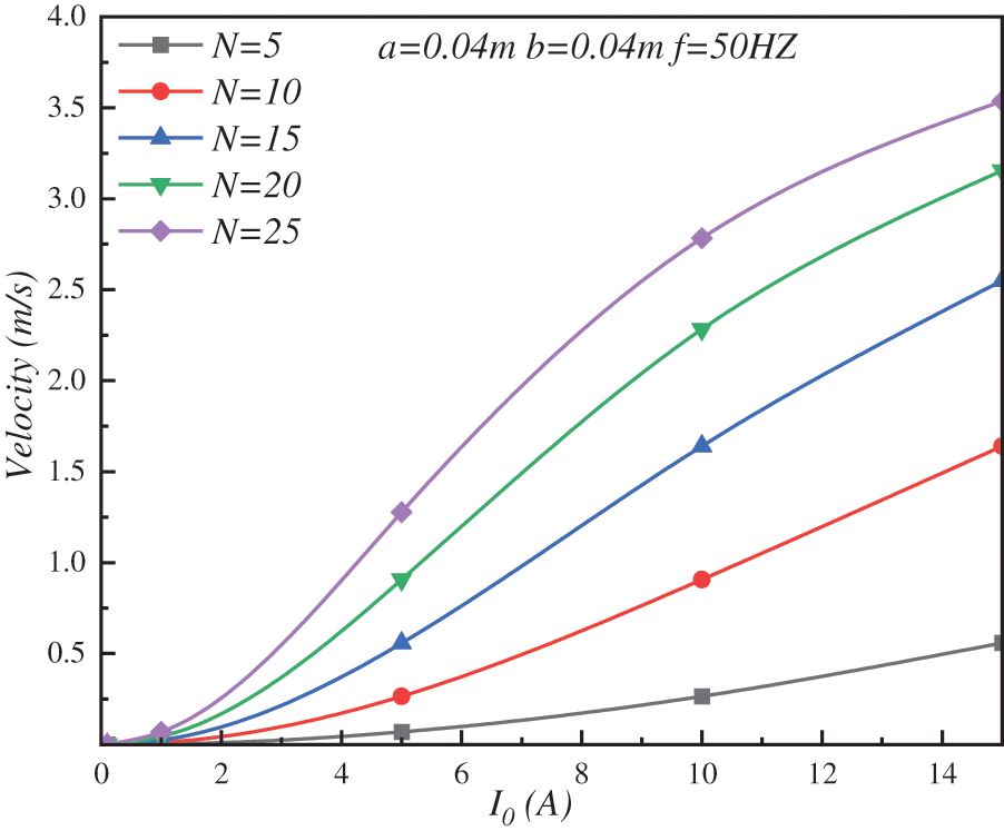
Figure 5: Variation of average velocity of working fluid with current intensity
3.3 Effect of Frequency on the Working Fluid Flow Rate
Because the induction pump works with a three-phase alternating current, the frequency of the alternating current is a factor that cannot be neglected. Fig. 6 shows the change in average work rate with frequency, wherein, the higher the frequency, the more similar the average work rate and the frequency were to the linear variability. The increase was most pronounced at larger coil turns. This was when the induced magnetic flux was greater, and the working fluid was significantly impacted by the applied magnetic fields. By analyzing the corresponding turns of the coil at higher speeds, it was apparent that the frequency increased from 20 to 60 Hz, and the maximum work rate increased by about 241% when the other parameters were kept the same.
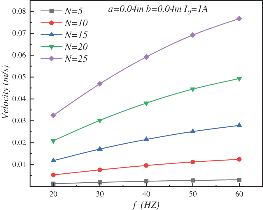
Figure 6: Variation of average flow rate of working fluid with frequency
3.4 Effect of Number of Coil Turns on the Working Fluid Flow Rate
The coil winding process is an important factor affecting electromagnetic properties, in which the number of coil turns directly influences the strength of the induction magnetic field, thus affecting the fluid flow. The variation of the mean flow velocity of the working fluid with the number of turns of the coil is shown in Fig. 7. These results demonstrated that the liquid metal transport speed could be significantly increased by increasing the number of turns of the coil under constant current resistance. The liquid metal flow velocity was then non-linear with the winding number. As the number of coils increased, the effect of increasing the liquid metal flux increased. As the number of coils was increased from 10 to 25 in the same frequency range, the mean working fluid flow rate increased by a maximum of approximately 618%; when frequency was held constant, increasing the number of coils significantly increased the mean flow rate of the working fluid only at high current intensities. At a current of 15 A, the number of rotations of the coil increased from 10 to 25, and the liquid metal transport velocity increased by about 216%.
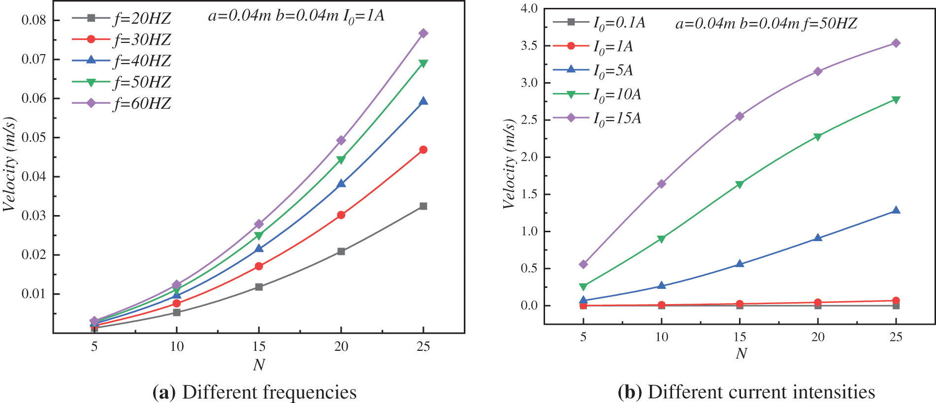
Figure 7: Variation of average velocity of working fluid with the number of turns of the coil
3.5 Effect of Coil Winding Size on the Working Fluid Flow Rate
In practical engineering, the winding of a coil has some bearing on electromagnetic properties, particularly when the number of loops is fixed, and one of the common ways to control electromagnetic properties is often by the size of the coil. Fig. 8 illustrates how the working fluid flow rate varied with coil winding size. It shows that the average flow rate of the working fluid in the induction pump was related to the winding height of the coil a and not the winding width b. As shown in Fig. 4, increasing the coil winding height a could increase the transport speed of liquid metal by increasing the magnetic field passing through the area where the working fluid acts. Therefore, when designing the coil shape, the winding width of the coil can be used as a secondary adjustment parameter. In addition, the results in Fig. 8 show that the transport speed of the liquid metal decreased when the coil height increased to a certain extent.
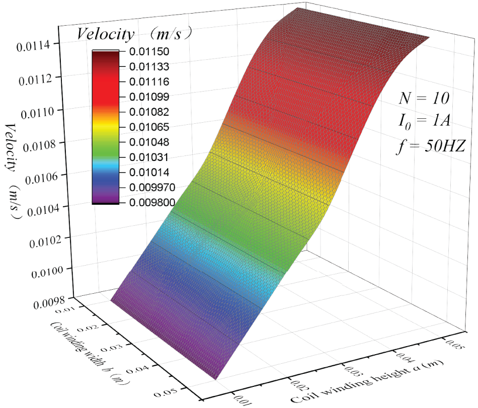
Figure 8: Variation of the working fluid flow rate with coil winding size
Based on research into the induction pump liquid lithium metal flow process during cold treatment, this paper established a numerical model of the coupling of the electromagnetic field and the flow field. To investigate the influence of the induction pump parameters on the fluid flow field during liquid metal transport, an analysis of the effects of current strength, frequency, winding number, and winding size on the work rate was presented, providing a benchmark for subsequent experimental work. The main conclusions are as follows:
(1) Increasing the current intensity can significantly improve the flow rate of the working fluid in the induction pump. The improvement effect becomes more apparent as the number of turns of the coil increases. As the winding number was increased from 10 to 25 turns, this corresponded to a maximum increase of about 618% in the mean flow rate of the working fluid.
(2) For liquid metals, the mean flow velocity and frequency are close to the law of linear change, and increasing the frequency value can improve the liquid metal flow velocity to some degree and improve the stability of the flow. The maximum increase in mean flow velocity was approximately 241% as the frequency was increased from 20 to 60 Hz.
(3) The average liquid metal flow rate in the induction pump was related to the winding height a of the coil, but not to the coil winding width b. As the height of the coil was increased up to a certain point there was a decreasing trend of the increase in flow rate of the working fluid.
In future, the model will introduce a temperature field variable to realize multiphysics field coupling of the induction pump in a high temperature environment and lay the groundwork for optimal pump design.
Acknowledgement: None.
Funding Statement: The authors received no specific funding for this study.
Author Contributions: Study conception and design: He Wang, Ying He; data collection: Ying He; analysis and interpretation of results: He Wang; draft manuscript preparation: Ying He. All authors reviewed the results and approved the final version of the manuscript.
Availability of Data and Materials: The datasets used and/or analysed during the current study are available from the corresponding author on reasonable request.
Conflicts of Interest: The authors declare that they have no conflicts of interest to report regarding the present study.
References
1. Jamshed, W., Gowda, R. J. P., Kumar, R. N., Prasannakumara, B. C., Nisar, K. S. et al. (2022). Entropy production simulation of second-grade magnetic nanomaterials flowing across an expanding surface with viscidness dissipative flux. Nanotechnology Reviews, 11(1), 2814–2826. [Google Scholar]
2. Sreenivasa, B. R., Alaa, J. F., Abdulmohsen, A., Alzahrani, H. A. H., Malik, M. Y. (2022). Numerical study of heat transfer mechanism in the flow of ferromagnetic hybrid nanofluid over a stretching cylinder. Waves in Random & Complex Media, 1–17. [Google Scholar]
3. Gowda, R. J. P., Sarris, I. E., Kumar, R. N., Kumar, R., Prasannakumara, B. C. (2022). A three-dimensional non-newtonian magnetic fluid flow induced due to stretching of the flat surface with chemical reaction. Journal of Heat Transfer, 144(11), 113602. [Google Scholar]
4. Li, Q., Xuan, Y. M., Wang, J. (2005). Experimental investigations on transport properties of magnetic fluids. Experimental Thermal and Fluid Science, 30(2), 109–116. [Google Scholar]
5. Montag, P., Howes, G. G. (2022). A field-particle correlation analysis of magnetic pumping. Physics of Plasmas, 3, 032901. [Google Scholar]
6. Benos, L. T., Mahabaleshwar, U. S., Sakanaka, P. H., Sarris, I. E. (2019). Thermal analysis of the unsteady sheet stretching subject to slip and magnetohydrodynamic effects. Thermal Science and Engineering Progress, 13, 100367. [Google Scholar]
7. Li, Y. X., Khan, M. I., Gowda, R. J. P., Arfan, A., Farooq, S. et al. (2021). Dynamics of aluminum oxide and copper hybrid nanofluid in nonlinear mixed marangoni convective flow with entropy generation: Applications to renewable energy. Chinese Journal of Physics, 73, 275–287. [Google Scholar]
8. Benos, L. T., Karvelas, E. G., Sarris, I. E. (2019). Crucial effect of aggregations in CNT-water nanofluid magnetohydrodynamic natural convection. Thermal Science and Engineering Progress, 11, 263–271. [Google Scholar]
9. Jyothi, A. M., Kumar, R. N., Gowda, R. J. P., Prasannakumara, B. C. (2021). Significance of Stefan blowing effect on flow and heat transfer of casson nanofluid over a moving thin needle. Communications in Theoretical Physics, 73(9), 263–271. [Google Scholar]
10. Sarris, I. E. (2022). An MHD fluid flow over a porous stretching/Shrinking sheet with slips and mass transpiration. Micromachines, 13(1), 116. [Google Scholar] [PubMed]
11. Cao, R., Yuan, J., Zhao, F., Kong, X., Peng, G. et al. (2022). Probability-driven identification mechanism for degradation of magnetic drive pumps. Measurement Science and Technology, 33, 115302. [Google Scholar]
12. Araseki, H., Kirillov, I. R., Preslitsky, G. V., Ogorodnikov, A. P. (2006). Magnetohydrodynamic instability in annular linear induction pump. Nuclear Engineering & Design, 227(9), 29–50. [Google Scholar]
13. Varma, V. B., Pattanaik, M. S., Cheekati, S. K., Ramanujan, R. V. (2022). Superior cooling performance of a single channel hybrid magnetofluidic cooling device. Energy Conversion and Management, 223, 113465. [Google Scholar]
14. Alsulami, M. D., Abdulrahman, A., Kumar, R. N., Gowda, R. J. P., Prasannakumara, B. C. (2023). Three-dimensional swirling flow of nanofluid with nanoparticle aggregation kinematics using modified Krieger Dougherty and Maxwell Bruggeman models: A finite element solution. Mathematics, 11, 2081. [Google Scholar]
15. Haim, H. (2022). Applications of magneto electrochemistry and magnetohydrodynamics in microfluidics. Magnetochemistry, 8(11), 140. [Google Scholar]
16. Kim, H. R., Yong, B. L. (2011). A design and characteristic experiment of the small annular linear induction electromagnetic pump. Annals of Nuclear Energy, 38(5), 1046–1052. [Google Scholar]
17. Kim, H. R., Kwak, J. S. (2016). MHD design analysis of an annular linear induction electromagnetic pump for SFR thermal hydraulic experimental loop. Annals of Nuclear Energy, 92, 127–135. [Google Scholar]
18. Wang, L., Hou, Y., Shi, L., Wu, Y., Tian, W. et al. (2019). Experimental study and optimized design on electromagnetic pump for liquid sodium. Annals of Nuclear Energy, 124, 426–440. [Google Scholar]
19. Rey, F., Roman, C., Courtessole, C., Dumont, M., Letout, S. et al. (2014). Modeling of fully coupled MHD flows in annular linear induction pumps. International Journal of Applied Electromagnetics & Mechanics, 44(2), 155–162. [Google Scholar]
20. Abdullina, K. I., Bogovalov, S. V., Zaikov, Y. P. (2018). 3D numerical modeling of liquid metal turbulent flow in an annular linear induction pump. Annals of Nuclear Energy, 111(2), 118–126. [Google Scholar]
21. Araseki, H., Kirillov, I. R., Preslitsky, G. V., Ogorodnikov, A. P. (2004). Magnetohydrodynamic instability in annular linear induction pump: Part I. Experiment and numerical analysis. Nuclear Engineering & Design, 227(1), 29–50. [Google Scholar]
22. Boisson, J., Klochko, A., Daviaud, F., Padilla, V., Aumatre, S. (2012). Travelling waves in a cylindrical magnetohydrodynamically forced flow. Physics of Fluids, 24(4), 273–147. [Google Scholar]
23. Gea, V., Nacke, B. (2016). Numerical simulation of core-free design of a large electromagnetic pump with double stator. Magnetohydrodynamics, 52(3), 417–431. [Google Scholar]
24. Shaker, S. F., Hajjawi, M., Khan, A., Kilani, M. (2023). Effect of inlet and outlet angles on the flow performance of the ferrofluidic magnetic micropump. Cogent Engineering, 10, 2158611. [Google Scholar]
25. Kirillov, I. R., Obukhov, D. M. (2005). Completely two-dimensional model for examining the characteristics of a linear cylindrical induction pump. Technical Physics, 50(8), 999–1005. [Google Scholar]
26. Dementjev, S., Groeschel, F., Ivanov, S. (2008). Concept of electromagnetic pump for liquid metal target for Swiss spallation neutron source. 7th International Pamir Conference Fundamental and Applied MHD. Presqu’île de Giens, France. [Google Scholar]
27. Ivanov, S. (2010). On a concept of electromagnetic pump for the liquid metal target for routine operation in the Swiss spallation neutron source. Magnetohydrodynamics, 46(1), 59–68. [Google Scholar]
28. Alzabut, J., Nadeem, S., Noor, S., Eldin, S. M. (2023). Numerical analysis of magnetohydrodynamic convection heat flow in an enclosure. Results in Physics, 51, 106618. [Google Scholar]
29. Cosoroabaa, E., Caicedoa, C., Maharjana, L., Clarkb, A., Wua, M.et al. (2019). 3D multiphysics simulation and analysis of a low temperature liquid metal magnetohydrodynamic power generator prototype. Sustainable Energy Technologies and Assessments, 35, 180–188. [Google Scholar]
30. Yan, J. W., Mao, J., Xiong, B. L. (2022). Numerical simulation of laminar MHD flows in conducting ducts with deformed parallel walls. Nuclear Fusion and Plasma Physics, 42(4), 448–454. [Google Scholar]
31. Zhang, S. C., Cao, W. H. (2023). Study on flow and heat transfer characteristics in magnetic nanofluids microchannels. Cryogenics & Superconductivity, 51(4), 58–65. [Google Scholar]
Cite This Article
 Copyright © 2024 The Author(s). Published by Tech Science Press.
This work is licensed under a Creative Commons Attribution 4.0 International License , which permits unrestricted use, distribution, and reproduction in any medium, provided the original work is properly cited.
 Downloads
 Citation Tools