
 Submit a Paper
 Propose a Special lssue
 Open Access
ARTICLE

Thermo-Hydraulic Performances of Microchannel Heat Sinks with Different Types of Perforated Rectangular Blocks
1 School of Physics and Electronic Information Engineering, Hubei Engineering University, Xiaogan, 432000, China
2 Wuhan National Laboratory for Optoelectronics (WNLO), Huazhong University of Science and Technology, Wuhan, 430074, China
3 Institute of Engineering and Technology, Hubei University of Science and Technology, Xianning, 437100, China
* Corresponding Author: Xiao Xiao. Email:
Fluid Dynamics & Materials Processing 2025, 21(1), 87-105. https://doi.org/10.32604/fdmp.2024.056577
Received 25 July 2024; Accepted 25 October 2024; Issue published 24 January 2025
 View Full Text
 Download PDF
Abstract
The behavior of single-phase flow and conjugate heat transfer in micro-channel heat sinks (MCHS) subjected to a uniform heat flux is investigated by means of numerical simulations. Various geometrical configurations are examined, particularly, the combinations of rectangular solid and perforated blocks, used to create a disturbance in the flow. The analysis focuses on several key aspects and related metrics, including the temperature distribution, the mean Fanning friction factor, the pressure drop, the Nusselt number, and the overall heat transfer coefficient across a range of Reynolds numbers (80–870). It is shown that the introduction of such blocks significantly enhances the heat transfer performances of the MCHS compared to the straight-through flow channel. Specifically, a case is found where the Nusselt number increases by 2.3 times relative to the reference case. The integration of perforated blocks facilitates the generation of vorticity within the channel, promoting the mixing of cold and hot fluids. Notably, MCHS incorporating perforated rectangular blocks exhibit more pronounced heat transfer benefits at Reynolds numbers smaller than 400.Keywords
As feature sizes shrink and clock frequencies increase, managing the heat generated by high-power electronics, such as central processing units (CPUs), graphics processors (GPUs), projectors, light-emitting diodes (LEDs), and high-power lasers, is becoming more challenging. It’s clear that total power consumption is rising, and power distribution across the device area is highly uneven [1]. Currently, the high-performance microprocessor chip, specifically the AMD TR 3970X, has a Thermal Design Power (TDP) rated at 280 watts. Under peak load conditions, the heat flux generated can surpass 220 watts per square centimeter [2]. Furthermore, the International Technology Roadmap for Semiconductors (ITRS) specifies that to ensure the safe operation of semiconductor devices, their junction temperature must be maintained below 85 degrees Celsius [3].
The use of microchannel heat sink (MCHS) has become increasingly popular in high-density integrated electronic circuits with higher operational frequencies, as they require efficient heat dissipation.
The MCHS, a cooling technique, was initially developed by Tuckerman et al. in 1981 [4]. Their design resulted in a maximum temperature increase of 71°C above the water inlet temperature, with a pressure drop of 2.2 bar. Following the pioneering work of Tuckerman and Pearse, extensive research has been conducted to enhance the thermal and hydraulic performance of MCHS. Steinke et al. [5] undertook an analytical examination of the friction factor associated with single-phase liquid flows in MCHS, engaging in an exhaustive evaluation of experimental data to pinpoint inconsistencies. Rosa et al. [6] conducted a comprehensive review of both experimental and numerical data pertaining to single-phase heat transfer at the micro-scale. They determined that the heat transfer mechanisms within MCHS can generally be well-explained by the theoretical models and correlations developed for the macro scale. Nonetheless, they highlighted that it is crucial to take into account the scaling effects, which involve various factors such as the entrance length effect, conjugate heat transfer phenomena, viscous dissipation, and the impact of temperature on fluid properties. Jilte et al. [7] examined the cooling properties of a recirculating flow heat sink with four distinct channel configurations. The findings demonstrated that the heat removal rate of the Nano fluid-cooled device exceeded that of the water-cooled counterpart. A multitude of experimental and numerical investigations have been executed to assess the thermal performance of MCHS, primarily concentrating on microchannels with smooth interior surfaces [8–11]. Hybrid nanofluids might boost thermal and heat transfer efficiency over single or standard coolants. Extensive research, including both numerical and experimental studies, has explored their thermal and exergetic performance in microchannel cooling systems [12,13]. Owing to the miniature dimensions of the channels, the flow within microchannels tends to be predominantly laminar. Nevertheless, in certain application contexts, it has been shown that inducing turbulent flow within MCHS can yield enhanced thermal performance over that of laminar flow [14–17]. Consequently, microchannels with smooth interiors may not be adequate for applications where higher heat transfer demands are necessary.
Numerous other studies have focused on examining the impact of cross-sectional shapes on the hydrothermal performance of MCHS by investigating various shapes, including circular, triangular, and trapezoidal [18–21]. Gunnasegaran et al. [22] conducted a numerical study on the influence of three different cross-sectional channel shapes, namely rectangular, trapezoidal, and triangular MCHS. The findings indicated that the rectangular MCHS demonstrated the highest heat transfer enhancement. In a similar vein, Alfaryjat et al. [23] conducted a numerical study to assess the effects of three distinct shapes—hexagonal, circular, and rhombus—on the performance of Microchannel Heat Exchange Systems (MCHS). The findings indicated that the hexagonal-shaped MCHS had the highest heat transfer coefficient, whereas the MCHS with a rhombus cross-section demonstrated the lowest friction factor.
Although MCHS can achieve high thermal performance, further enhancements are needed to address the increasing thermal requirements of electronic devices. Ribs represent a widely utilized method of flow disruption, extensively implemented to augment heat transfer. This is attributed to their effectiveness in disrupting and reforming thermal boundary layers, as well as enhancing mixing via the creation of vortices and chaotic advection.
Chai et al. [24–26] performed a computational study to evaluate the effects on heat transfer and fluid dynamics within a microchannel heat sink that was equipped with ribs in a fan shape. This analysis focused on the impact of three principal geometric factors: the height, width, and pitch of the ribs, and also considered two rib arrangement methods: in-line and staggered. The research results indicated that ribs characterized by shorter heights and wider spacings were more effective in enhancing heat transfer efficiency. Specifically, the study concluded that microchannels with forward triangular offset ribs achieved the highest performance at Reynolds numbers below 350, while semi-circular ribs exhibited the highest performance at Reynolds numbers exceeding 400. In a separate study, Hong et al. [27] conducted research on forced convection heat transfer within a microchannel heat sink that incorporated finned structures. Their findings indicated that by fine-tuning the dimensions of the strip fins, it was possible to achieve enhancements in thermal efficiency while also minimizing the associated pressure drop.
Li et al. [28] compared the thermal efficiency of heat sinks with varying cavity and rib shapes on the sidewall. Their findings indicated that heat transfer improves as the thermal boundary layer is redeveloped. The researchers also underscored the significant impact of cavity and rib structures on the heat transfer properties of each heat sink. In a separate study by Soleymani et al. [29], a novel heat sink design was presented. This design incorporates two distinct regions: a background zone comprising rectangular microchannels and a hotspot zone composed of rounded rectangular pin-fins and NACA 0024 airfoil pin-fins. Through the optimization of the pin-fin geometry, this design effectively mitigated the heat flux in the hotspot region. In their work, Ding et al. [30] introduced an efficient design that combines in-line and staggered micro-pin fins within the core areas and single-layer baffles around them. This arrangement effectively optimized the trade-off between pumping power and heat transfer efficiency, leading to a reduction in Tmax from 332.3 to 324.3 K, along with a 148% rise in pressure drop.
Utilizing materials with superior thermal properties in the construction of MCHS is a passive technique that can enhance their thermal performance [31]. Ceramic materials are known for their exceptional stability at high temperatures and minimal deformations under harsh conditions [32–35]. Certain ceramics and ceramic matrix composites exhibit excellent thermal properties that make them suitable for use in mini/micro heat channel heat sinks [36,37].
Vajdi et al. [38] investigated a study on heat transfer and fluid flow in a ZrB2 heat sink using water as a coolant. The results showed that the heat sink’s maximum temperature could be maintained below 360 K by dissipating a heat flux of 3.6 MW/m2. Fattahi et al. [39] performed numerical simulations of a heat exchanger made of AlN. The research indicated that heat exchangers constructed from AlN could achieve a 59% improvement in heat transfer compared to those made from Al2O3. Additionally, the effectiveness of the heat exchanger was found to be enhanced by 26%. Two additional ceramic materials, titanium diboride (TiB2) and beryllium oxide (BeO), exhibit outstanding thermophysical properties [40–43]. There is a growing interest in the application of these ceramic materials for thermal management and efficient energy utilization.
Furthermore, some researchers proposed more innovative pin–fin arrangement configurations. Gao et al. [44] performed an experimental and numerical study to improve the comprehensive performance of microchannel heat sinks integrated with various arrangements of micro pin-fin arrays. Studies reveal that the pin-fin arrangements featuring a mix of uniform and gradient staggered designs exhibit the highest pressure losses but offer a balanced thermal dissipation capability. In contrast, configurations with a full distribution of pin-fins outperform all other partial pin-fin arrangements in terms of heat transfer efficiency. Shi et al. [45] have introduced a pin fin structure with a staggered flow guidance design. A numerical study has been conducted to assess its thermal and hydraulic properties at different heights and densities, and the findings have been juxtaposed with those of the traditional rectangular pin fin setup. The outcomes indicate that this structure notably enhances heat dissipation efficiency and temperature uniformity, without adversely affecting the pressure drop. Inspired by the Clematis Montana flower, Xu et al. [46] and his team have crafted an innovative structure resembling a petal. The heat transfer coefficients (HTCs) and frictional pressure drops (FPDs) for R113 in both pin fin and plate channels, each with a height of 1 mm, were examined under atmospheric conditions. The experiments were conducted with a mass flux (G) ranging from 50 to 250 kg/m²s and a heat flux (q) between 5 and 140 kW/m². The pin fin channel slightly outperformed the plate channel in terms of HTCs. These HTCs were significantly influenced by the heat flux (q) and showed no correlation with the mass flux (G) or vapor quality (x), indicating that nucleate boiling predominantly governed the heat transfer process. Pandy et al. [47] have developed a density-based topology optimization technique that is utilized for creating free-form and non-traditional fin structures. The study indicates that refining the dimensions of drop-oblique-trapezoidal and oval-shaped (DOTO) fins can significantly improve the efficiency of heat sinks.
The complex variations in the internal flow channel structure of microchannels can effectively enhance the overall heat dissipation performance of the microchannel heat sink, such as offset strips, protrusions, recesses, and louvers. The refined design incorporates a variety of angles, widths, and spacings, coupled with a diminished channel height, all aimed at controlling the pressure drop. A pivotal element of this research is the thorough optimization of these variables. The innovative design features additional branches within the channel, positioned at intervals that become shorter as the design progresses. These branches are sparser at the inlet where the flow is still nascent, and their concentration grows as one moves towards the outlet. Such a configuration promotes the re-establishment of the boundary layer and augments the intermingling of the flow. In this research, a variety of microchannel flow setups have been designed, each with a unique pattern of rectangular block perforations, labeled as Cases 1 to 5. These configurations have been analyzed through simulation across a Reynolds number span from 80 to 870. The objective of this study is to evaluate the thermal and frictional characteristics, to understand the mechanisms behind heat transfer, and to identify the most effective setup by assessing the thermohydraulic performance.
The heat sink is composed of a series of parallel rectangular flow channels. Fig. 1 displays a simplified representation of a basic rectangular microchannel, and Table 1 lists the detailed structural measurements. The current study takes into account the computational model of a microchannel heat sink that features five rectangular blocks with perforations, along with their respective configurations of dimensional parameters, as shown in Fig. 2. Case 1 includes a rectangular block and a perforated block; Case 2 includes a perforated block and a rectangular block; Case 3 is a combination of periodic perforated blocks and rectangular blocks, where the rectangular block is longer; Case 4 is a combination of periodic rectangular blocks and perforated blocks, where the perforated block is longer; Case 5 is a periodic combination of perforated blocks. To grasping the variations in fluid dynamics and heat transfer, a comparison is made using a simple rectangular microchannel. Given the periodic nature of the microchannel heat sink, and to minimize the mesh cell count and computational time, only a portion of the structure is considered for the current numerical simulation, as depicted in Fig. 1. In the computational model, two half-walls are positioned on either side of the channel.
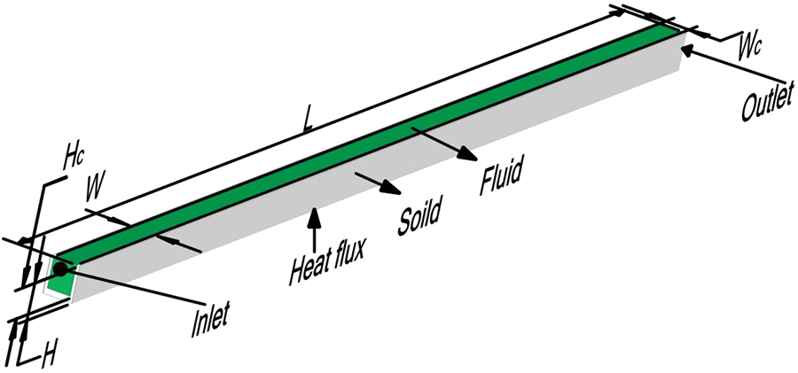
Figure 1: Schematic diagram of the three-dimensional configuration of a simple rectangular microchannel
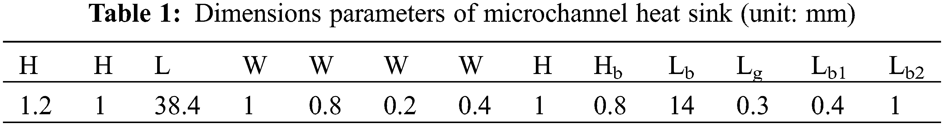
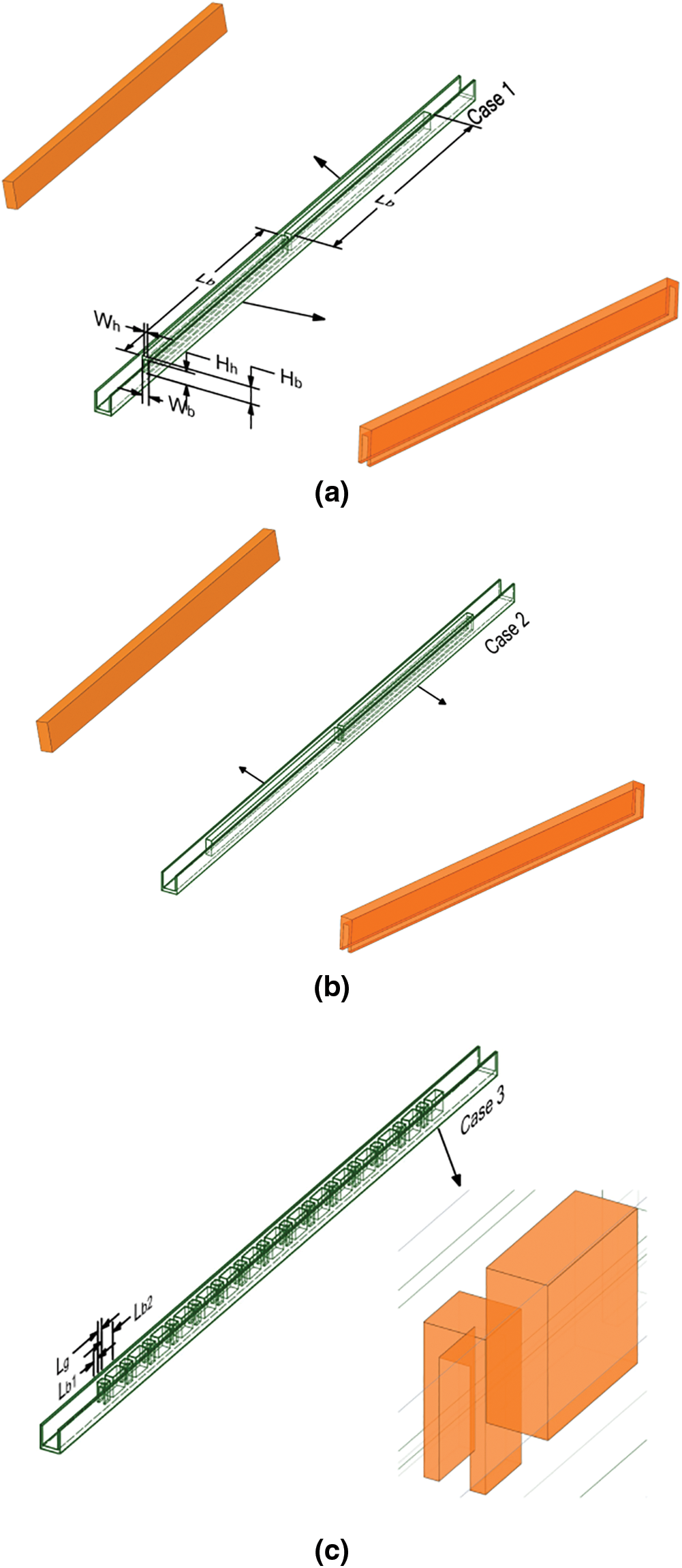
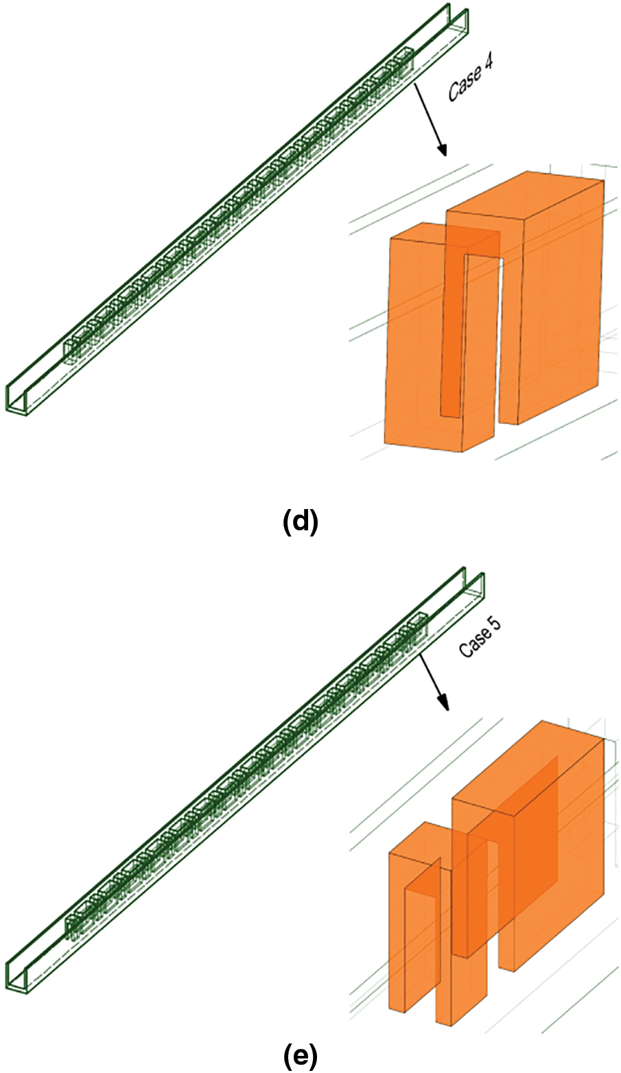
Figure 2: Different configurations of microchannels (a: Case 1, b: Case 2, c: Case 3, d: Case 4, e: Case 5)
In MCHS, flow is typically laminar, with the critical Reynolds number falling within the range of 1000 to 1500 [48,49]. As such, this study employs a laminar flow model for the numerical analysis, maintaining the Reynolds number for the fluid flow under 1500. The specific dimensions of the model used in this numerical simulation are presented in Table 1.
When developing the numerical model for internal flow and heat transfer in microchannel heat sinks, the following assumptions are made [24]: (1) The fluid in the microchannels is incompressible, with no phase changes, and the flow is laminar; a three-dimensional, steady-state numerical simulation method is employed. The material properties of the solid components within the microchannel heat sink are considered uniform and unaffected by temperature changes. (2) Due to the small scale of the microchannel heat sink, temperature gradients are deemed insignificant, resulting in the omission of radiative heat transfer from the analysis. In the heat transfer range discussed in this paper, forced convection is predominant over natural convection, thus the latter is not considered. (3) Except for the surface designated for heating, all other surfaces are modeled as adiabatic.
Under the aforementioned assumptions, the governing equations for continuity, momentum, and energy for the fluid domain are formulated as follows [24–26]:
In this context, U represents the velocity vector of the fluid, P denotes the pressure, and T signifies the temperature. The variables
In the case of the solid domains, the velocity vector is zero, necessitating the use of only the energy equation, which can be formulated as follows [24–26]:
Here,
2.3 Boundary Conditions and Computational Procedure
In the numerical simulation calculations of this paper, the boundary conditions are set as follows. A velocity inlet boundary condition is applied at the inlet of the heat sink, with the fluid inlet temperature specified as a constant value (
The base surface of the heat sink is uniformly heated by a constant heat flux (
In this study, the computational fluid dynamics (CFD) software ANSYS FLUENT 2023 R1 is employed to obtain numerical solutions. The Finite Volume Method (FVM) was employed along with the relevant boundary conditions. For the analysis of the flow field, the SIMPLE algorithm was utilized, while the convective term was approximated using a second-order upwind differencing scheme. The diffusion terms in both the energy and momentum equations were approximated using a second-order central difference method [16]. To ensure the convergence of the solution, residual criteria of 10−6 are set for all variables, encompassing velocity components, temperature, and mass. Before the discretization of the governing equations, mesh generation is carried out within the computational domains.
2.4 Data Reduction and Formulation
The definitions for the Reynolds number (Re) and the hydraulic diameter (Dh) are as follows [24]:
Here, ρf signifies the volumetric average density of the fluid, um is the mean velocity of flow in the unobstructed channel segment, and μf refers to the fluid’s dynamic viscosity.
The mean Fanning friction factor (f) and the pressure drop (Δp) can be determined through the following method [24]:
Δpin and Δpout represent the average pressures at the inlet and outlet of the channel, respectively, while L denotes the length of the entire channel.
The average heat transfer coefficient h and Nusselt number Nu are expressed as [24]:
In the equation, qw represents the heat flux density, Ab denotes the area of the heat source, and ΔT represents the logarithmic mean temperature difference between the microchannel wall and the cooling fluid.
To assess the overall effectiveness of various microchannels, this study utilizes a Performance Evaluation Criterion (PEC). The PEC is calculated as the ratio between the heat transfer coefficient of a microchannel equipped with rectangular block inserts and that of a microchannel without any inserts, with the condition that both are operating at the same pump power [24].This is calculated as follows:
The terms Nu0 and f0 correspond to the Nusselt number and friction factor respectively for the basic rectangular channel.
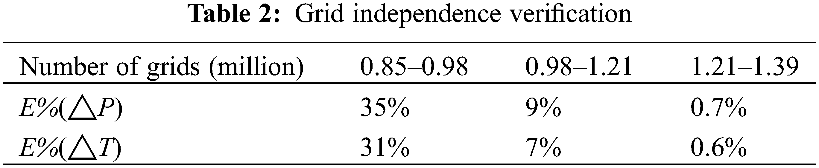
Owing to the intricate nature of the numerical domain, the fluid region is discretized using an unstructured grid through the Fluent meshing process. Fig. 3 illustrates the computational grid used in Case 0. Four different density mesh computational models are used to calculate the pressure drop at the inlet and outlet to verify the accuracy of the model calculations as uin = 1 m/s and q = 40 W/cm². The difference between the mesh division with the highest number of grids and the other three types of grid divisions is represented by Eq. (12) [24], where M2 denotes the mesh division with the most grids, and M1 represents the other three grid divisions with fewer grids. As can be seen from Table 2, under the conditions of 1.21 million to 1.39 million grid divisions, the difference in pressure drop at the inlet and outlet of the heat sink is 0.7%, which is less than 1%. The temperature difference between the inlet and outlet of the heat sink is 0.6%, which is also less than 1%. The numerical calculations under these two mesh division conditions can be considered accurate, and considering the optimization of computational resources, a grid count of 1.21 million is selected for the numerical calculation of the rectangular straight microchannel heat sink model. Other models also follow this method to verify grid independence.
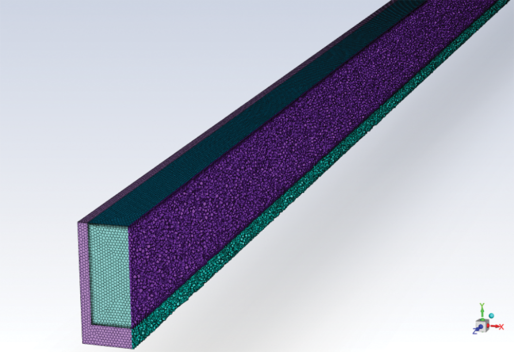
Figure 3: Computational grid for Case 0
2.6 Validation with Experimental Data
To validate the reliability of the numerical computation methods used in this model, the pressure drop and fluid temperature difference numerical results for the inlet and outlet of the rectangular straight microchannel heat sink model were compared with experimental data [48]. As shown in Figs. 4 and 5, the figures present a comparison of the pressure difference and temperature difference at the inlet and outlet of the microchannel heat sink under different Reynolds numbers. It is evident from the figures that the discrepancies with the experimental results for both temperature difference and pressure drop are less than 10%. Therefore, this confirms the precision of the numerical computation methods used in this simulation.
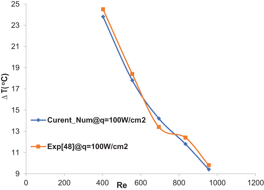
Figure 4: Comparison of temperature difference between numerical simulation and experiment [48]
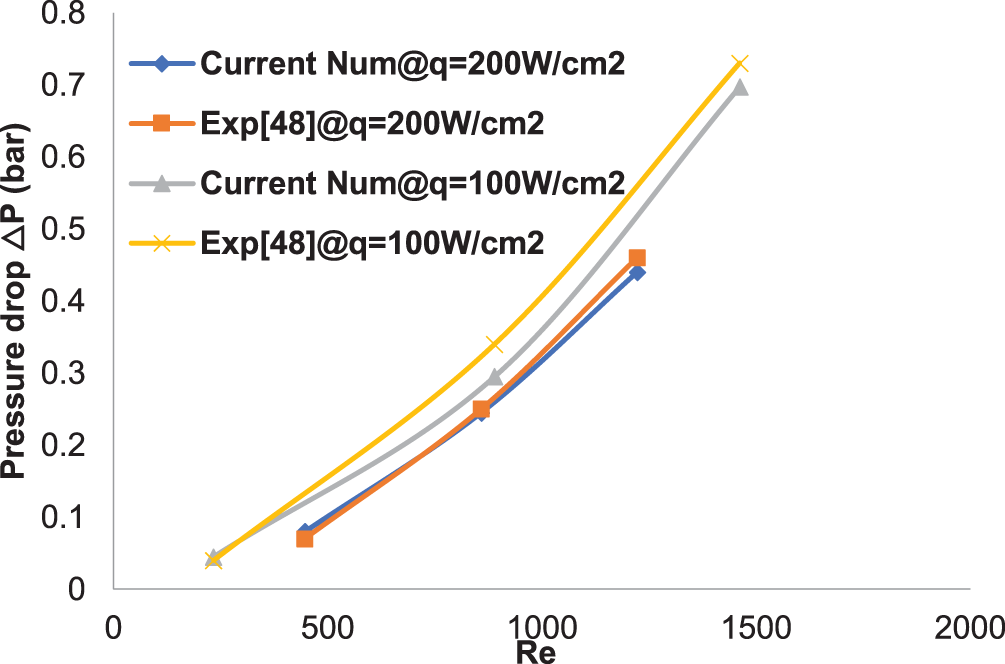
Figure 5: Comparison of pressure drop between numerical simulation and experiment [48]
This section details the outcomes of numerical simulations performed using ANSYS FLUENT 2023 R1. It explores the impact of various channel optimization designs, such as the integration of perforated rectangular blocks with standard rectangular blocks, and the diverse configurations of these two disturbance types, specifically in Cases 1 through 5. The study thoroughly examines their influence on temperature profiles, average fanning friction factors, pressure losses, Nusselt numbers, and the overall heat transfer performance coefficient. The main objective of this research is to improve the heat sink’s capabilities by optimizing thermal transfer efficiency and minimizing pressure drop, thereby ensuring a more even temperature distribution. This is crucial for cooling systems that need to maintain temperatures for the dependability and performance of electronic equipment.
To analyze the impact of five optimized channel structures on the flow characteristics of a heat sink, Fig. 6 presents the velocity contour (at the y = 0.25 mm cross-section) under the initial conditions of a heat flux density of 40 W/cm² at the base of the heat sink, an inlet velocity of 1.2 m/s, and an inlet fluid temperature of 300 K for the optimized channel structures. It is evident from the figure that in Case 0, due to the absence of any disturbance structures within the channel, the fluid velocity in the center of the channel is higher than that near the channel walls, resulting in a clear stratification of fluid velocities, which is detrimental to the thorough mixing of cold and hot fluids. In the channel structures of Case 1 to Case 5, where disturbance structures have been introduced, Fig. 6 clearly shows different stratifications of fluid velocities before and after the disturbance structures. From Case 1 and Case 2, it can be seen that the introduction of disturbance structures interrupts the fluid velocity, causing the high-velocity fluid in the center of the channel to mix thoroughly with the low-velocity fluid near the channel walls after entering the interrupted area, due to the relatively larger fluid space in the interrupted region, leading to an overall reduction in fluid velocity within the interrupted area. At the exit of the interrupted region, the contraction of the fluid channel due to the structure causes the fluid to form a higher pressure, leading the fluid to gather towards the center of the interruption at the exit, where the velocity is lower and the pressure is relatively smaller, creating a reverse pressure gradient. Case 3 and Case 4 introduce additional periodic rectangular blocks and perforated rectangular blocks within the channel, which periodically mix high and low-velocity fluids, generating periodic pressure gradients, reducing the laminar stagnation zone, and facilitating the mixing of cold and hot fluids. Case 5, building on Case 3 and Case 4, further perforates the rectangular blocks. This structural design of the blocks causes the fluid to form more interrupted areas within the channel. The presence of these interrupted areas not only leads to more mixing of cold and hot fluids within the areas but also creates a velocity-weak zone near the center of the channel, with relatively higher velocities near the two channel walls. This periodic interrupting structure effectively disrupts the velocity boundary layer, allowing for more efficient mixing of high and low-velocity fluids within this region.
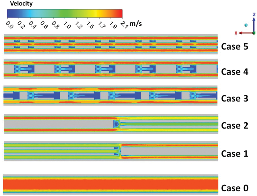
Figure 6: The velocity distribution in the x–z middle cross-section
Fig. 7 presents the velocity streamline diagrams for the five optimized structures. In Case 0, since no rectangular blocks are introduced, the flow field distribution throughout the channel is relatively uniform. In Cases 1 and 2, the introduction of interruption structures clearly generates vortices at the intervals of the rectangular blocks, and similar vortex formations can also be observed in Cases 3 and 4. The inclusion of these rectangular and perforated block structures periodically creates more interruption intervals, which alter the speed and direction of fluid flow, thereby affecting the fluid’s boundary layer. The presence of interruption structures leads to more complex flow patterns within the boundary layer, influencing it by altering the velocity distribution inside the boundary layer, making the fluid more prone to mixing and forming vortex flow. This vortex flow accelerates heat transfer, thereby enhancing the heat dissipation efficiency of the heat sink. Moreover, the interruption structures can disturb the flow within the boundary layer, creating more irregular fluid motion, increasing the degree of fluid mixing, and steepening the velocity gradient within the boundary layer. At the same time, these vortices that change the speed and direction of fluid flow can reduce fluid flow resistance, decrease energy consumption, increase the contact area of the fluid, speed up heat transfer, and strengthen the efficiency of heat exchange. In Case 5, since all the rectangular blocks have been perforated, the interruption intervals for the fluid are further increased, resulting in the formation of fluid vortices at every interval of the blocks. It is worth noting that although the formation of vortices near the rectangular blocks can fully mix the cold and hot fluids, continuously breaking down the thermal boundary layer, and thereby enhancing the heat transfer capability, the presence of the stagnation area near the blocks also increases the thermal resistance. This weakens the convective heat transfer process between the fluid around the blocks and the wall surface, which to some extent affects the heat transfer performance of the microchannel.
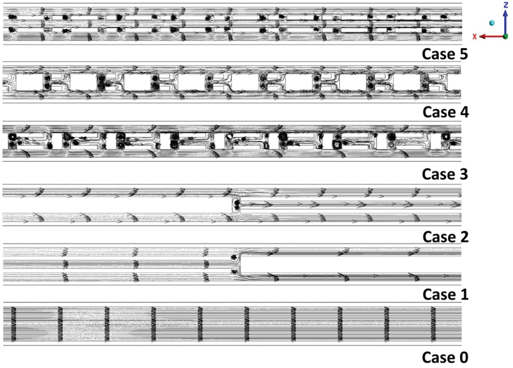
Figure 7: The streamline patterns within the x–z planes for all cases at a channel height of 0.25 mm
Fig. 8 shows the pressure distribution at the y = 0.25 mm cross-section for six different configurations under an inlet velocity of 1.2 m/s and a heat flux density of 40 W/cm2. Among Case 0 to Case 5, the fluid transport pressure decreases in the direction of fluid flow. Particularly in Case 3 to Case 5, where multiple blocks and perforated blocks are introduced, the pressure drop is irregular and particularly concentrated in the areas near the blocks. This indicates that the non-smooth structure of the microchannel impedes the flow, being the main source of increased pressure drop in microchannels. In these three optimized structures, the fluid continuously expands and contracts near the blocks, forming interlaced flows. These blocks and perforated blocks cause an increase in pressure drop, and the interlaced flow disrupting the boundary layer flow state more significantly increases the pressure drop of the microchannel heat sink.
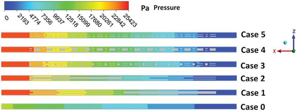
Figure 8: The pressure distribution across the mid x–z cross-sectional plane
The local pressure drop within the flow channels of these three structures varies, but the total pressure drop is essentially the same, so within a certain Reynolds number range, local high pressure drops cannot become the decisive factor for the overall pressure drop. Due to the introduction of blocks and perforated blocks, the equivalent diameter of the flow channel periodically contracts and expands, which is beneficial for fluid flow within a low Reynolds number range. However, as Re increases, the pressure loss caused by the fluid becomes more pronounced. In Case 4, since only the smaller rectangular blocks are perforated, there is a larger pressure gradient when the fluid encounters non-perforated rectangular blocks, and at the same time, the equivalent diameter of the main flow channel decreases after being obstructed by the rectangular blocks, therefore the pressure drop in the Case 4 structure is the greatest.
Fig. 9 displays the varying patterns of the friction factor ratio (f/f0) for the straight-through microchannel and the five optimized structure microchannels at different Reynolds numbers when the heat flux is 40 W/cm2. As expected, compared to the straight-through microchannel, the friction factors for the optimized structure microchannels all increase. The increase in friction factor is due to the rectangular blocks and perforated blocks in the fluid flow path, which expand the channel surface and provide additional flow resistance for the fluid flow. It can also be seen from the figure that as Re increases, the f/f0 for various optimized structures shows an increasing trend, with Case 5 having the highest f/f0 value. This is mainly because Case 5 periodically arranges more rectangular blocks and perforated blocks, and the introduction of these blocks causes disturbances and obstructions to fluid flow, leading to changes in the fluid flow path and uneven velocity distribution, thereby increasing the frictional resistance of the fluid. In Case 5, the fluid has to overcome greater resistance caused by the blocks, making the fluid flow more complex, which leads to an increase in the friction factor.
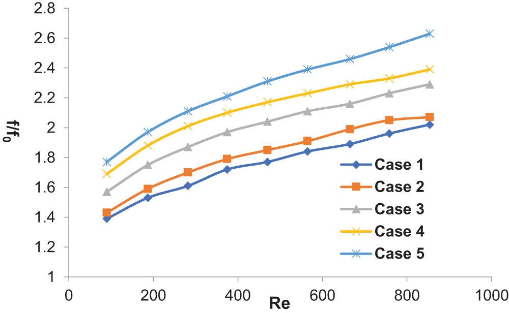
Figure 9: the Darcy friction factors for MCHS incorporating flow obstructions, across Cases 1 to 5, normalized against Case 0. The subscript “0” indicates the reference case, which is Case 0
Temperature cloud maps of through-type flow channels and optimized structure flow channels are shown in Fig. 10. The initial conditions of this cloud map (cross-section at y = 0.25 mm) are as follows: the heat flux density at the bottom surface is 40 W/cm², and the inlet flow velocity is 1.2 m/s. From the cloud map, it can be observed that in Case 0, the fluid has the highest temperature at the outlet, while in Case 4, the fluid has the lowest temperature at the outlet. In Case 0, no blocks are added, while only a small amount of blocks are added in Case 1 and Case 2, which reduces the overall disturbance of the fluid, resulting in a thinner thermal boundary layer and consequently an increased temperature gradient. In Case 3 to Case 5, the number of rectangular blocks and perforated blocks increases, causing the flow path of the fluid to bifurcate and increasing the interaction between the fluid and the solid surface. This exacerbates the periodic interruption of the boundary layer, which is beneficial for enhancing the heat exchange between cold and hot fluids. The addition of these periodically increased blocks increases the overall disturbance of the fluid, leading to a reduction in the temperature gradient. In Case 4 and Case 5, the temperature exhibits a wavelike distribution because the fluid undergoes lateral flow in the interrupted structure. As mentioned above, this type of flow, when the fluid flows along the channel direction, allows for better mixing of cold and hot fluids. Fig. 10 also shows that the temperature difference between the inlet and outlet of the microchannel heat sink with a combination of rectangular blocks and perforated rectangular blocks (Case 3–Case 5) are lower than those of the traditional rectangular channel. This indicates that the use of rectangular blocks or perforated rectangular blocks in the channel enhances the heat transfer performance of the heat sink. This is because the internal disturbance structures in the channel can promote the formation of secondary flows and ensure the mixing of the central flow with the fluid near the wall surface, which strengthens the fluid disturbance and thins the thermal boundary layer, with Case 5 showing the best heat transfer effect. However, the generation of these secondary flows and the mixing process of the fluid are mostly accompanied by pressure drop losses. The pressure cloud map of the flow channel given in Fig. 8 also confirms this point; except for the traditional rectangular channel, adding periodic disturbance structures in the channel will increase the pressure drop between the inlet and outlet of the coolant. Therefore, establishing a balance between enhanced heat transfer and pressure drop loss is essential for finding the optimal structure with the best comprehensive heat transfer and fluid performance. To select the optimal structure, this part is discussed in detail in Section 3.3.
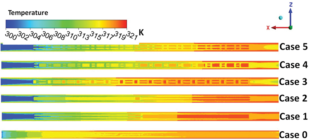
Figure 10: The temperature distribution across the mid x–z cross-sectional plane
Fig. 11 illustrates the variation of the Nusselt number for each optimized model at a heat flux of 40 W/cm2 under different Reynolds numbers. It can be observed from the figure that in all model structures, the Nusselt number increases with the increase in the Reynolds number, indicating that the heat sink will exhibit enhanced thermal transfer capabilities. Compared to the straight-through microchannels, the microchannels with optimized structures have higher Nusselt numbers. This is primarily because the introduction of rectangular blocks and perforated blocks expands more heat conduction surfaces, which aids in the mixing of cold and hot fluids, and the boundary layers near each block will re-develop, as described in Fig. 11. It is also evident that the performance of Case 5 is superior to that of other optimized structure microchannels. The presence of rectangular blocks and perforated blocks disrupts the temperature profile, thereby preventing the thermal boundary layer from fully developing. The re-establishment of the thermal boundary layer, coupled with the enhanced fluid mixing due to the expanded surfaces, collectively contribute to the improvement of heat transfer performance.
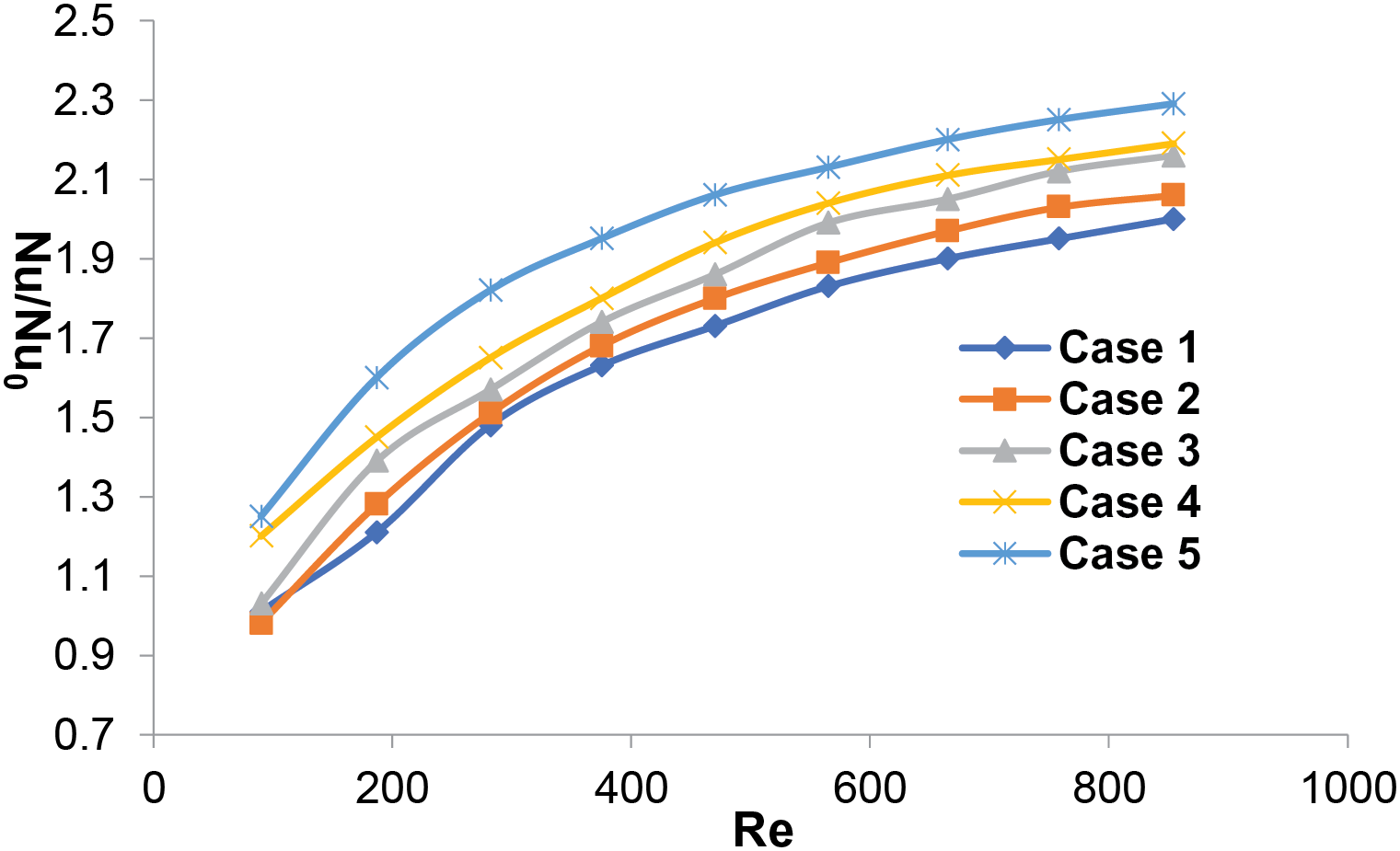
Figure 11: the comparative heat transfer performance of MCHS with varying design configurations, specifically Cases 1 through 4, in reference to Case 0 (The subscript “0” refers to the baseline scenario, Case 0)
Additionally, it is evident from the figure that when Re varies between 100 and 400, there is a significant increase in Nu/Nu0, and after Re exceeds 400, the rate of increase in Nu/Nu0 slows down. This is primarily due to the fact that at lower Reynolds numbers, the flow is more affected by the presence of the blocks, leading to more pronounced changes in the heat transfer characteristics. As the Reynolds number increases beyond 400, the disturbance of the fluid becomes more severe when it flows in the channel., and the effects of the blocks on the flow and heat transfer become less pronounced, resulting in a slower rate of increase in the Nusselt number ratio.
Fig. 12 shows the variation of the overall heat transfer performance coefficient (PEC) with respect to the Reynolds number when the heat flux is 40 W/cm2. In all cases, the overall heat transfer performance coefficient of the optimized structure microchannels is greater than 1, demonstrating the significance of optimized structure microchannels in enhancing the performance of straight-through microchannels. Across the entire range of Reynolds numbers, Case 5 consistently outperforms Cases 1 to 4 in overall thermal performance, but this advantage diminishes after the Reynolds number exceeds 400. This could be attributed to the slowdown in the rate of increase of the Nusselt number for Case 5 compared to the increase in friction factor as the Reynolds number increases. Therefore, within different Reynolds number regions, the trends in Nusselt number and friction factor affect the changes in heat transfer effectiveness. In this study’s optimized structures, when Re is less than 400, the increase in the Nusselt number primarily drives the improvement in the overall heat transfer performance coefficient; however, when Re is greater than 400, the increase in friction factor begins to negatively impact the heat transfer effectiveness, leading to a downward trend in the comprehensive heat transfer performance. Thus, Case 5 exhibits the most optimal overall heat transfer efficiency, which is also confirmed by the heat dissipation analysis presented earlier. Therefore, the periodic addition of rectangular blocks and perforated blocks within the channel is beneficial for enhancing the comprehensive thermal transfer effectiveness of the heat sink, albeit at the cost of greater pressure loss.
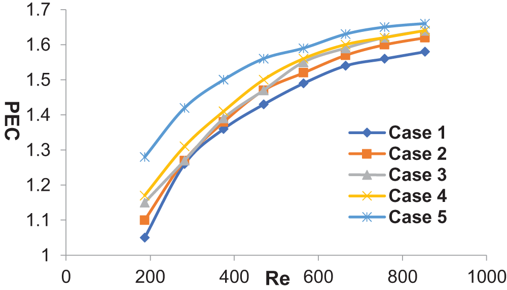
Figure 12: The PEC for MCHS with distinct design configurations, namely Cases 1 through 5, in comparison to Case 0 (The subscript “0” refers to the benchmark scenario, Case 0)
In this study, numerical simulations are utilized to provide a quantitative analysis of the variations in thermal efficiency and fluid dynamic properties among different channel configurations (Case 0–Case 5) in MCHS. The effects of different channel optimization structures, including the combination of perforated rectangular blocks with rectangular blocks and various arrangements of these two types of blocks, specifically Cases 1 to 5, on temperature distribution, mean fanning friction factor, pressure drop, nusselt number, and overall heat transfer performance coefficient are comprehensively investigated for a range of Reynolds numbers (80–870). The structure and geometry of the channel as well as the heating flux are fixed. The main findings can be summarized as follows:
(1) Compared with straight-through microchannel heat sinks (Case 0), the heat transfer performance of microchannel heat sinks with blocks is higher; periodic rectangular blocks create transverse recirculation zones within the flow channel, and periodic perforated rectangular blocks create longitudinal recirculation zones. The interaction of these two effects enhances the fluid disturbance within the optimized structure of the microchannel heat sink, thereby strengthening the heat transfer performance.
(2) In contrast to the straight-through microchannel heat sink, the incorporation of perforated rectangular blocks and rectangular blocks into the flow channel creates a larger heat transfer area, which facilitates the enhancement of heat exchange effectiveness.
(3) Among the evaluated scenarios, the optimized flow channel (Case 5) shows a 2.3-fold increase in the Nusselt number compared to the conventional straight-through flow channel (Case 0). Additionally, Case 5’s friction factor is 2.6 times greater than that of Case 0. Case 5 exhibits the most favorable overall heat transfer characteristics, with a 29% improvement in thermal exchange efficiency in comparison to Case 0.
(4) Incorporating a module of perforated rectangular blocks into the flow channel facilitates the formation of vortices, which promotes the mixing of cold and hot fluids, consequently improving heat transfer efficiency.
(5) When the Reynolds number is below 400, the perforated rectangular blocks significantly enhance the overall heat transfer performance of the MCHS. Additionally, when the Reynolds number exceeds 400, the improvement effect declines.
Acknowledgement: We are grateful to Senior Engineer Tang for his insightful feedback and engaging conversations regarding the subject matter of our research.
Funding Statement: This research was funded by the Project of the Hubei Provincial Department of Science and Technology (Grant No. 2022CFB957), the Project of Hubei Engineering University of Teaching Research (Grant No. JY2024032), Ministry of Education University-Industry Cooperation Collaborative Education Project (Grant No. 220903584161245), College Students’ Innovation and Entrepreneurship Training Program (Grant Nos. DC2024031, DC2024032).
Author Contributions: The authors confirm contribution to the paper as follows: conceptualization: Heng Zhao and Xiao Xiao; data curation: Heng Zhao, Honghua Ma, Hui Liu and Yongjun Xiao; software: Heng Zhao; validation, Heng Zhao, Huaqing Yu, Yongjun Xiao and Xiang Yan; writing—original draft preparation: Heng Zhao, Xiao Xiao and Hui Liu; writing: Heng Zhao; funding acquisition: Xiang Yan; supervision: Xiao Xiao; project administration: Heng Zhao and Xiao Xiao. All authors reviewed the results and approved the final version of the manuscript.
Availability of Data and Materials: The data that support the findings of this study are available from the corresponding author upon reasonable request.
Ethics Approval: Not applicable.
Conflicts of Interest: The authors declare no conflicts of interest to report regarding the present study.
References
1. Kang Y, Luo ZB, Deng X, Cheng P, Peng C, He W, et al. Numerical study of a liquid cooling device based on dual synthetic jets actuator. Appl Therm Eng. 2023;219(2):119691. doi:10.1016/j.applthermaleng.2022.119691. [Google Scholar] [CrossRef]
2. Ramakrishnan B, Alissa H, Manousakis I. CPU overclocking: a performance assessment of air, cold plates, and two-phase immersion cooling. IEEE Trans Compon Pack Manuf Technol. 2021;11(10):1703–15. doi:10.1109/TCPMT.2021.3106026. [Google Scholar] [CrossRef]
3. Prajapati YK, Pathak M, Khan MK. Transient heat transfer characteristics of segmented finned microchannels. Exp Therm Fluid Sci. 2016;79(5):134–42. doi:10.1016/j.expthermflusci.2016.07.004. [Google Scholar] [CrossRef]
4. Tuckerman DB, Pease RFW. High-performance heat sinking for VLSI. IEEE Electron Device Lett. 1981;2(5):126–9. doi:10.1109/EDL.1981.25367. [Google Scholar] [CrossRef]
5. Steinke ME, Kandlikar SG. Single-phase liquid friction factors in microchannels. Int J Therm. 2006;45(11):1073–83. doi:10.1016/j.ijthermalsci.2006.01.016. [Google Scholar] [CrossRef]
6. Rosa P, Karayiannis TG, Collins MW. Single-phase heat transfer in microchannels: the importance of scaling effects. Appl Therm Eng. 2009;29(17–18):3447–68. doi:10.1016/j.applthermaleng.2009.05.015. [Google Scholar] [CrossRef]
7. Jilte R, Ahmadi MH, Kumar R, Kalamkar V, Mosavi A. Cooling performance of a novel circulatory flow concentric multi-channel heat sink with nanofluids. Nanomater. 2020;10(4):647. doi:10.3390/nano10040647. [Google Scholar] [PubMed] [CrossRef]
8. Cho ES, Choi JW, Yoon JS, Kim MS. Experimental study on microchannel heat sinks considering mass flow distribution with non-uniform heat flux conditions. Int J Heat Mass Tran. 2010;53(9–10):2159–68. doi:10.1016/j.ijheatmasstransfer.2009.12.026. [Google Scholar] [CrossRef]
9. Mohammed Adham A, Mohd-Ghazali N, Ahmad R. Thermal and hydrodynamic analysis of microchannel heat sinks: a review. Renew Sustain Energy Rev. 2013;21(5):614–22. doi:10.1016/j.rser.2013.01.022. [Google Scholar] [CrossRef]
10. Zhao CY, Lu TJ. Analysis of microchannel heat sinks for electronics cooling. Int J Heat Mass Tran. 2002;45(24):4857–69. doi:10.1016/S0017-9310(02)00180-1. [Google Scholar] [CrossRef]
11. Kim DK, Kim SJ. Averaging approach for microchannel heat sinks subject to the uniform wall temperature condition. Int J Heat Mass Tran. 2006;49(3–4):695–706. doi:10.1016/j.ijheatmasstransfer.2005.08.012. [Google Scholar] [CrossRef]
12. Saadoon ZH, Ali FH, Sheikholeslami M. Numerical study on heat transfer improvement with Fe3O4 and Ag-H2O nanofluids in converge-diverge mini-channel heat sinks. Mater Today: Proc. 2023;80(6):2983. doi:10.1016/j.matpr.2021.07.091. [Google Scholar] [CrossRef]
13. Selimefendigil F, Öztop HF. Analysis of hybrid nanofluid and surface corrugation effects on laminar convective heat transfer in an encapsulated PCM-filled vertical cylinder with POD-based modeling. Int J Heat Mass Transf. 2021;178(4):121623. doi:10.1016/j.ijheatmasstransfer.2021.121623. [Google Scholar] [CrossRef]
14. Li YF, Xia GD, Ma DD, Jia YT, Wang J. Characteristics of laminar flow and heat transfer in microchannel heat sink with triangular cavities and rectangular ribs. Int J Heat Mass Tran. 2016;98:17–28. doi:10.1016/j.ijheatmasstransfer.2016.03.022. [Google Scholar] [CrossRef]
15. Okab AK, Hasan HM, Hamzah M, Egab K, Al-Manea A, Yusaf T. Heat transfer and fluid flow analysis in a microchannel heat sink with sidewall dimples and fillet profile. Int J Thermofluids. 2022;15(5):100192. doi:10.1016/j.ijft.2022.100192. [Google Scholar] [CrossRef]
16. Chai L, Xia GD, Wang HS. Laminar flow and heat transfer characteristics of interrupted microchannel heat sink with ribs in the transverse microchambers. Int J Therm Sci. 2016;110:1–11. doi:10.1016/j.ijthermalsci.2016.06.029. [Google Scholar] [CrossRef]
17. Feng Z, Luo X, Guo F, Li H, Zhang J. Numerical investigation on laminar flow and heat transfer in rectangular microchannel heat sink with wire coil inserts. Appl Therm Eng. 2017;116:597–609. doi:10.1016/j.applthermaleng.2017.01.091. [Google Scholar] [CrossRef]
18. Razali A, Sadikin A. CFD simulation study on pressure drop and velocity across single flow microchannel heat sink. J Adv Res Des. 2015;8(1):12–21. [Google Scholar]
19. Abubakar SB, Nor Azwadi CS. Numerical prediction of laminar nanofluid flow in rectangular microchannel heat sink. J Adv Res Fluid Mech Therm Sci. 2015;7(1):29–38. [Google Scholar]
20. Noh NM, Fazeli A, Nor Azwadi CS. Numerical simulation of nanofluids for cooling efficiency in microchannel heat sink. J Adv Res Fluid Mech Therm Sci. 2014;4:13–23. [Google Scholar]
21. Nitiapiruk P, Mahian O, Dalkilic AS, Wongwises S. Performance characteristics of a microchannel heat sink using TiO2/water nanofluid and different thermophysical models. Int Commun Heat Mass Transf. 2013;47:98–104. doi:10.1016/j.icheatmasstransfer.2013.07.001. [Google Scholar] [CrossRef]
22. Gunnasegaran P, Mohammed H, Shuaib N, Saidur R. The effect of geometrical parameters on heat transfer characteristics of microchannels heat sink with different shapes. Int Commun Heat Mass Transf. 2010;37(8):1078–86. doi:10.1016/j.icheatmasstransfer.2010.06.014. [Google Scholar] [CrossRef]
23. Alfaryjat A, Mohammed H, Adam NM, Ariffin M, Najafabadi M. Influence of geometrical parameters of hexagonal, circular, and rhombus microchannel heat sinks on the thermohydraulic characteristics. Int Commun Heat Mass Transf. 2014;52:121–31. doi:10.1016/j.icheatmasstransfer.2014.01.015. [Google Scholar] [CrossRef]
24. Chai L, Xia GD, Wang HS. Parametric study on thermal and hydraulic characteristics of laminar flow in microchannel heat sink with fan-shaped ribs on sidewalls—Part 1: heat transfer. Int J Heat Mass Transf. 2016;97:1069–80. doi:10.1016/j.ijheatmasstransfer.2016.02.077. [Google Scholar] [CrossRef]
25. Chai L, Xia GD, Wang HS. Parametric study on thermal and hydraulic characteristics of laminar flow in microchannel heat sink with fan-shaped ribs on sidewalls—Part 2: pressure drop. Int J Heat Mass Transf. 2016;97:1081–90. doi:10.1016/j.ijheatmasstransfer.2016.02.076. [Google Scholar] [CrossRef]
26. Chai L, Xia GD, Wang HS. Parametric study on thermal and hydraulic characteristics of laminar flow in microchannel heat sink with fan-shaped ribs on sidewalls—Part 3: performance evaluation. Int J Heat Mass Transf. 2016;97:1091–101. doi:10.1016/j.ijheatmasstransfer.2016.02.075. [Google Scholar] [CrossRef]
27. Hong F, Cheng P. Three dimensional numerical analyses and optimization of offset strip-fin microchannel heat sinks. Int Commun Heat Mass Tran. 2009;36(7):651–6. doi:10.1016/j.icheatmasstransfer.2009.02.015. [Google Scholar] [CrossRef]
28. Li M, Lai ACK. Thermodynamic optimization of ground heat exchangers with single U-tube by entropy generation minimization method. Energy Convers Manag. 2013;65:133–9. doi:10.1016/j.enconman.2012.07.013. [Google Scholar] [CrossRef]
29. Soleymani Z, Rahimi M, Gorzin M, Pahamli Y. Performance analysis of hotspot using geometrical and operational parameters of a microchannel pin-fin hybrid heat sink. Int J Heat Mass Transf. 2020;159:120141. doi:10.1016/j.ijheatmasstransfer.2020.120141. [Google Scholar] [CrossRef]
30. Ding B, Zhang ZH, Gong L, Xu MH, Huang ZQ. A novel thermal management scheme for 3D-IC chips with multicores and high power density. Appl Therm Eng. 2020;168:114832. doi:10.1016/j.applthermaleng.2019.114832. [Google Scholar] [CrossRef]
31. Kumaraguruparan G, Sornakumar T. Development and testing of aluminum micro channel heat sink. J Therm Sci. 2010;19:245–52. doi:10.1007/s11630-010-0245-8. [Google Scholar] [CrossRef]
32. Luo Y, Xie Y, Jiang H, Chen Y, Zhang L, Sheng X, et al. Flame-retardant and form-stable phase change composites based on MXene with high thermostability and thermal conductivity for thermal energy storage. Chem Eng J. 2021;420(3):130466. [Google Scholar]
33. Cao M, Chang Z, Tan J, Wang X, Zhang P, Lin S, et al. Superoxide radical-mediated self-synthesized Au/MoO3-x hybrids with enhanced peroxidase-like activity and photothermal effect for anti-MRSA therapy. ACS Appl Mater Interfaces. 2022;14(11):13025–37. doi:10.1021/acsami.1c23676. [Google Scholar] [PubMed] [CrossRef]
34. Wuchina E, Opeka M, Causey S, Buesking K, Spain J, Cull A, et al. Designing for ultrahigh-temperature applications: the mechanical and thermal properties of HfB2, HfCx, HfNx and αHf(N). J Mater Sci. 2004;39:5939–49. doi:10.1023/B:JMSC.0000041690.06117.34. [Google Scholar] [CrossRef]
35. Shahedi Asl M, Azizian-Kalandaragh Y, Ahmadi Z, Sabahi Namini A, Motallebzadeh A. Spark plasma sintering of ZrB2-based composites co-reinforced with SiC whiskers and pulverized carbon fibers. Int J Refract Metals Hard Mater. 2019;83:104989. doi:10.1016/j.ijrmhm.2019.104989. [Google Scholar] [CrossRef]
36. Zhang L, Pejaković DA, Marschall J, Gasch M. Thermal and electrical transport properties of spark plasma-sintered HfB2 and ZrB2 ceramics. J Am Ceram Soc. 2011;94:2562–70. doi:10.1111/jace.v94.8. [Google Scholar] [CrossRef]
37. Sadegh F, Vajdi M, Motallebzadeh A, Sha J. Numerical analyses of heat transfer and thermal stress in a ZrB2 gas turbine stator blade. Ceram Int. 2019;45(14):17742–50. doi:10.1016/j.ceramint.2019.05.344. [Google Scholar] [CrossRef]
38. Vajdi M, Sadegh Moghanlou F, Ranjbarpour Niari E, Shahedi Asl M, Shokouhimehr M. Heat transfer and pressure drop in a ZrB2 microchannel heat sink: a numerical approach. Ceram Int. 2020;46(2):1730–5. doi:10.1016/j.ceramint.2019.09.146. [Google Scholar] [CrossRef]
39. Fattahi M, Vaferi K, Vajdi M, Sadegh Moghanlou F, Sabahi Namini A, Shahedi Asl M. Aluminum nitride as an alternative ceramic for fabrication of microchannel heat exchangers: a numerical study. Ceram Int. 2020;46(8):11647–57. doi:10.1016/j.ceramint.2020.01.195. [Google Scholar] [CrossRef]
40. Nekahi S, Vajdi M, Sadegh Moghanlou F, Vaferi K, Motallebzadeh A, Özen M, et al. TiB2-SiC-based ceramics as alternative efficient micro heat exchangers. Ceram Int. 2019;45(15):19060–7. doi:10.1016/j.ceramint.2019.06.150. [Google Scholar] [CrossRef]
41. Vajdi M, Sadegh Moghanlou F, Ahmadi Z, Motallebzadeh A, Shahedi Asl M. Thermal diffusivity and microstructure of spark plasma sintered TiB2-SiC-Ti composite. Ceram Int. 2019;45(7):8333–44. doi:10.1016/j.ceramint.2019.01.141. [Google Scholar] [CrossRef]
42. Akishin GP, Turnaev SK, Vaispapir VY, Kiiko VS, Shein IR, Pletneva ED, et al. Composition of beryllium oxide ceramics. Refract Ind Ceram. 2011;51:377–81. doi:10.1007/s11148-011-9329-6. [Google Scholar] [CrossRef]
43. Ivanovskii AL, Shein IR, Makurin YN, Kiiko VS, Gorbunova MA. Electronic structure and properties of beryllium oxide. Inorg Mater. 2009;45:223–34. doi:10.1134/S0020168509030017. [Google Scholar] [CrossRef]
44. Cao W, Meng J, Qu ZG, Zhang JF. Experimental and numerical study on thermofluidic characteristics of microchannel heat sinks with various micro pin-fin arrays arrangement patterns. Appl Therm Eng. 2024;240:122236. doi:10.1016/j.applthermaleng.2023.122236. [Google Scholar] [CrossRef]
45. Shi ZR, Lan X, Cao J, Zhao N, Cheng Y. Numerical study of variable density and height flow guided pin fin in an open microchannel heat sink. Int J Heat Mass Transfer. 2024;225:125405. doi:10.1016/j.ijheatmasstransfer.2024.125405. [Google Scholar] [CrossRef]
46. Xu Y, Li L, Yan ZH. Experimental investigations of the flow boiling characteristics of green refrigerants in a novel petaloid micropin-fin heat sink. Int J Heat Mass Transfer. 2023;212:124243. doi:10.1016/j.ijheatmasstransfer.2023.124243. [Google Scholar] [CrossRef]
47. Pandey V, Lee SP. Maximizing liquid-cooled heat sink efficiency with advanced topology-optimized fin designs. Int J Heat Mass Transfer. 2024;229:125746. doi:10.1016/j.ijheatmasstransfer.2024.125746. [Google Scholar] [CrossRef]
48. Qu WL, Mudawar I. Experimental and numerical study of pressure drop and heat transfer in a single-phase micro-channel heat sink. Int J Heat Mass Transf. 2002;45(12):2549–65. doi:10.1016/S0017-9310(01)00337-4. [Google Scholar] [CrossRef]
49. Vanaki SM, Ganesan P, Mohammed HA. Numerical study of convective heat transfer of nanofluids: a review. Renew Sustain Energ Rev. 2016;54:1212–39. doi:10.1016/j.rser.2015.10.042. [Google Scholar] [CrossRef]
Cite This Article
 Copyright © 2025 The Author(s). Published by Tech Science Press.
This work is licensed under a Creative Commons Attribution 4.0 International License , which permits unrestricted use, distribution, and reproduction in any medium, provided the original work is properly cited.
 Downloads
 Citation Tools