
 Submit a Paper
 Propose a Special lssue
 Open Access
ARTICLE

Optimization of a Perforator Nozzle Based on the Constant Velocity of Jet Core
1 Oilfield Technology Branch, China Oilfield Services Limited, Langfang, 065201, China
2 School of Mechanical Engineering, Jiangsu University, Zhenjiang, 212013, China
3 Department of Chemical and Petroleum Engineering, University of Calgary, Calgary, AB T2N 1N4, Canada
* Corresponding Author: Weili Liu. Email:
(This article belongs to the Special Issue: Fluid and Thermal Dynamics in the Development of Unconventional Resources II)
Fluid Dynamics & Materials Processing 2025, 21(3), 645-656. https://doi.org/10.32604/fdmp.2025.059545
Received 10 October 2024; Accepted 10 December 2024; Issue published 01 April 2025
 View Full Text
 Download PDF
Abstract
Hydraulic sandblasting perforation plays a crucial role in the fracturing and reconstruction of unconventional oil and gas reservoirs. The jet nozzle is an essential part of the hydraulic perforation tool. Insufficient penetration depth, caused by excessive jet distances, presents challenges during the perforation process. To overcome this, an optimization design of the nozzle structure is required to enhance the perforation efficiency. In this paper, a computational fluid-dynamic model for conical-cylindrical nozzles has been elaborated. To further improve the rock-breaking efficiency of the jet nozzle, a fillet design is introduced at the nozzle inlet section. The SST k-ω model is employed to account for turbulent flow effects in submerged conditions. The results indicate that the nozzle’s geometric parameters greatly influence the flow characteristics. The orthogonal experimental method is employed to optimize the flow channel structure of the nozzle, taking the length of constant velocity core as the evaluation index. The following optimized geometric parameters for the conical-cylindrical nozzle have been determined accordingly: a cylindrical segment diameter of 3.2 mm, a contraction angle of 12°, a contraction segment length of 8 mm, a cylindrical segment length of 6.4 mm, and a fillet radius of 2 mm.Keywords
With the ongoing growth of global energy demand and the progressive depletion of conventional oil and gas resources, the development of unconventional oil and gas reservoirs has emerged as a prominent research focus within the energy sector [1]. In the process of unconventional oil and gas development, completion engineering is one of the key steps to ensure the effective extraction of oil and gas resources. Hydraulic sandblasting perforation is a common reservoir modification technology that uses high-pressure water flow combined with sand to penetrate the casing and formation, thereby increasing the drainage area of the reservoir [2,3]. As a commonly used completion tool, the performance of the hydraulic sandblasting perforator directly affects the production and economic benefits of oil and gas wells. During the implementation of the technology, engineering personnel introduce specialized high-pressure fracturing fluid into underground reservoirs. This liquid not only has enough pressure to penetrate rock layers, but its chemical properties are compatible with rocks and will not cause damage to the environment. By precisely controlling the injection rate and pressure of the liquid, technicians can effectively induce fractures in the rock formation, thereby improving the oil and gas flow performance of the reservoir. Hydraulic jetting in reservoirs utilizes high-pressure abrasive jets to create fractured tunnel channels within the reservoir rocks [4,5]. This technology can overcome the technical limitations of conventional hydraulic fracturing in low-permeability oil reservoirs. The network of fractures generated during the jetting process can increase the reservoir’s permeability and enhance overall production [6,7].
In the perforation transformation of reservoir sections at the bottom of the well, the complex geological conditions and the intricate interaction mechanisms between the jet flow and the reservoir rock pose significant challenges. Notably, an excessive spray distance can lead to energy attenuation of the jet, adversely affecting the perforation depth, which has become one of the key factors limiting perforation efficiency. Numerous studies indicate that the nozzle serves as the essential component of the hydraulic sandblasting perforator, significantly affecting the design of the internal flow channel [8–10]. This design choice directly influences the nozzle’s wear resistance and impact force, which ultimately affects the depth of rock fragmentation and the volume of rock broken during the perforation process. Additionally, the efficiency of hydraulic sandblasting perforation is influenced by the jet performance of the nozzle (simplified as jet performance), making it an essential part of the hydraulic sandblasting perforator.
Conical-cylindrical nozzles are commonly employed in hydraulic sandblasting perforation processes. However, they experience considerable energy loss, leading to a reduced fluid energy conversion rate, which constrains the maximum depth achievable in hydraulic sandblasting perforation [11]. Pan et al. [12] use computational fluid dynamics (CFD) to calculate jet performance of small-diameter nozzles, which offers a guidance for the flow channel structure optimization of nozzles. Researchers mainly use numerical calculation methods to study the flow field characteristics of small-diameter nozzles. However, in perforation operations, larger nozzle diameters consume more abrasives and water, consequently increasing operational costs [13,14]. Therefore, it is essential to optimize the design of other geometric parameters of the nozzle to balance performance and cost-effectiveness [15].
The internal shape of the nozzle significantly impacts on jet flow characteristics, while the optimal structure of the nozzles is greatly affected by the operation parameters [16]. Thus, it is essential to clarify the effects of nozzle structure on jet performance under the conditions of hydraulic sandblasting perforation in reservoirs, enabling the selection of high-performance nozzle geometries. Traditional nozzle design methods often rely on the experience of engineers and repeated experimentation, which not only results in long design cycles and high costs but also makes it challenging to ensure the optimality of the design [17]. With ongoing advancements in technology, numerical simulation methods are increasingly applied in the engineering field. By constructing a computational model of the water jet within the nozzle and utilizing computational fluid dynamics theory, it becomes possible to accurately simulate the fluid flow within the nozzle. This approach facilitates a more efficient design process, allowing for the systematic exploration of different geometric configurations and their corresponding jet performance, ultimately leading to optimized nozzle designs that enhance operational efficiency while reducing costs.
This study focuses on the conical-cylindrical nozzle with low processing costs and good jetting performance. The SST k-ω model is used to solve the jet flow field characteristics to clarify the distribution patterns of pressure and velocity fields. To further enhance the impact force of the nozzle, a fillet design is introduced at the nozzle inlet section. Then the orthogonal experimental method is used to design the flow channel structure of the nozzle, using the length of constant core as the evaluation index. The research results provide significant guidance for the geometrical parameters optimization of hydraulic sandblasting perforators.
Fig. 1 shows the geometric model of the nozzle jet flow field, which is obtained to analyze the jet performance in the internal and external limited regions of the nozzle. To further improve the jet performance of the nozzle, a fillet design is introduced at the nozzle inlet section. Five factors evident influence the flow field characteristics of the conical-cylindrical nozzle: fillet radius R, contraction angle θ, contraction segment length L1, cylindrical segment length L2, and cylindrical segment diameter D.
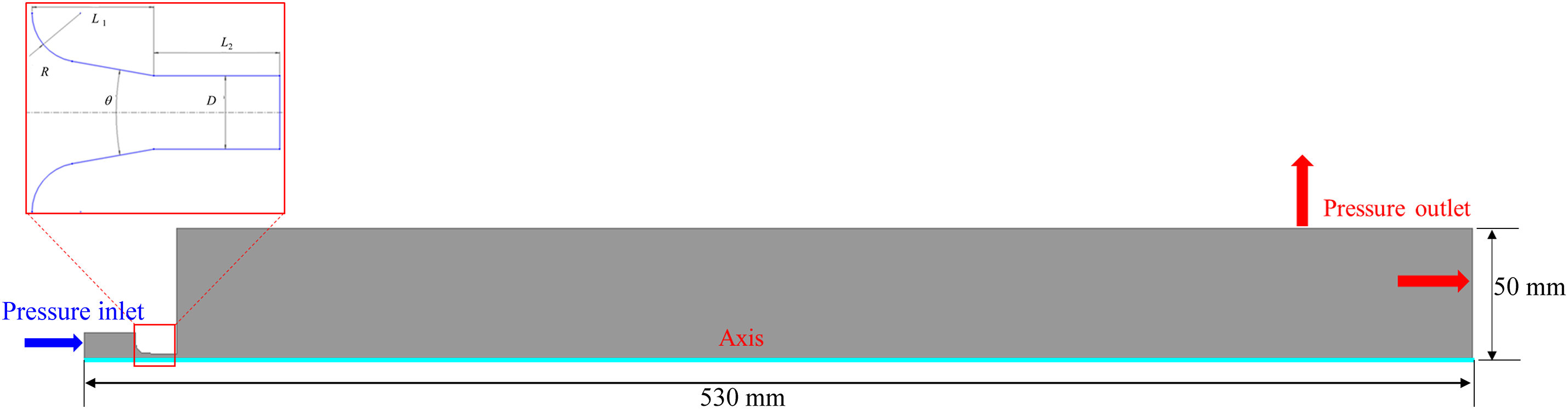
Figure 1: Physical model of nozzle jet and schematic diagram of conical-cylindrical nozzle flow channel structure
Grid meshing plays a vital role in numerical simulations. Using high-quality mesh is essential for achieving accurate computational results. The computational accuracy and time of the numerical simulation are influenced by the grid size. To ensure computational precision, it is important to minimize the number of grids as much as possible. To maintain accuracy, the boundary layer around the wall surfaces and the nozzle is refined, and a quadrilateral mesh is used for the grid generation of the jet flow field computational model [18].
In this paper, an analysis of grid independence is conducted to identify the suitable meshing strategy. Fig. 2 illustrates the influence of different mesh sizes on the flow rate and the length of constant velocity core. It is evident that the grid size has a minor effect on the flow rate, with a maximum change rate of 0.76%. Meanwhile, the length of constant velocity core increases as the grid size decreases. Based on the empirical value of the length of constant velocity core [19,20] (approximately 5–6 times the nozzle diameter), a mesh size of 0.5 mm is selected for the numerical calculations, with the computational mesh depicted in Fig. 3. The fluid domain is meshed into 151,910 grid elements.
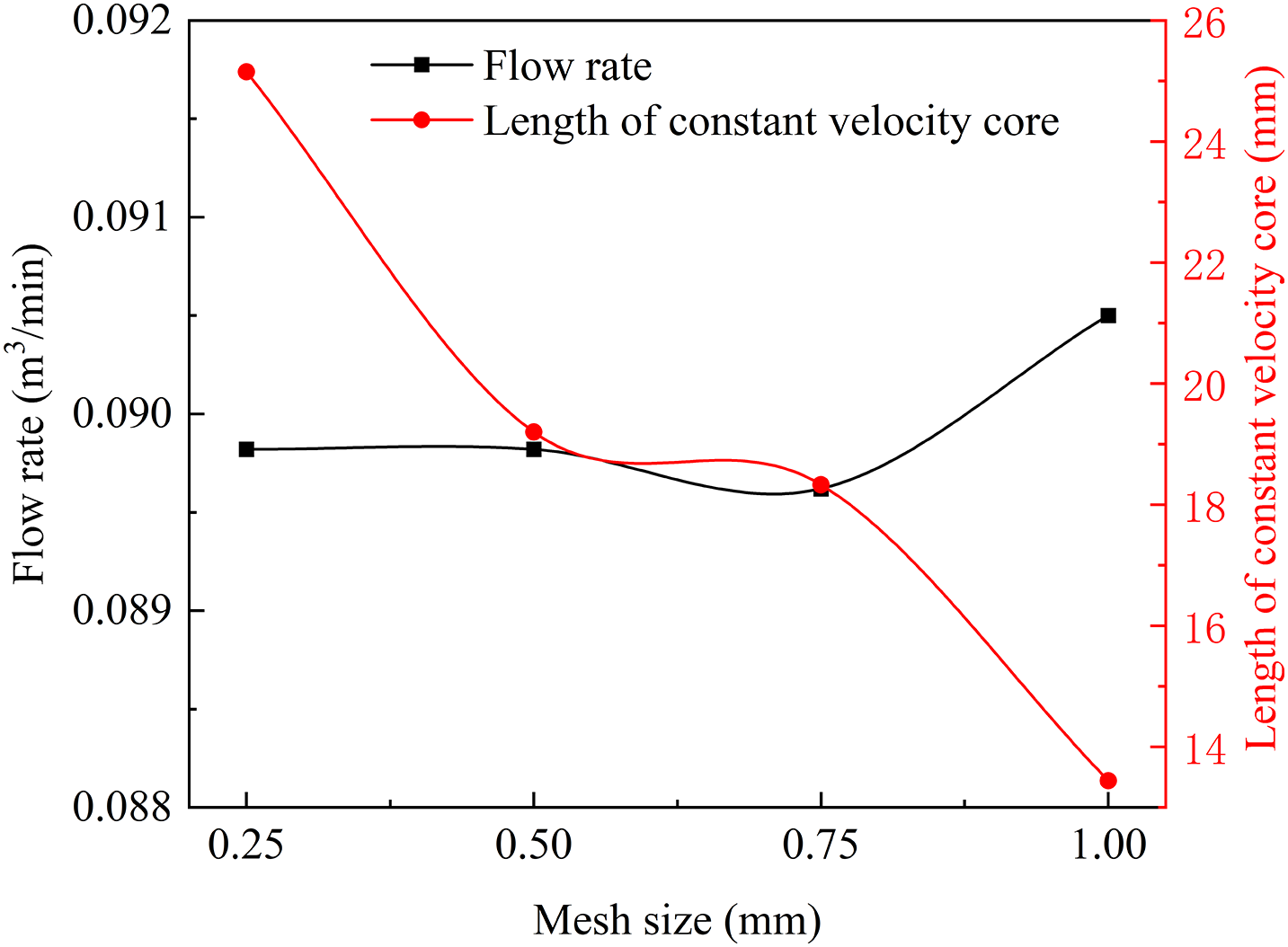
Figure 2: The influence of mesh size on flow rate and length of constant velocity core
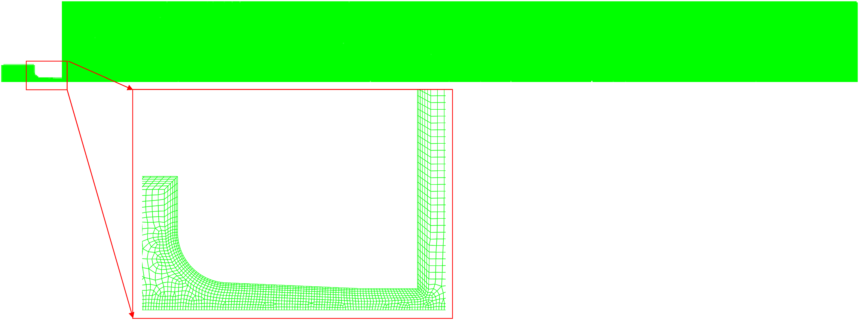
Figure 3: Computational mesh for the flow field of the water
Presently, numerous turbulence models exist, each with specific limitations and conditions under which they are applicable [21]. Through comparisons of commonly used k-ε and k-ω models, as well as multiple trials, it has been found that the SST k-ω model offers better accuracy and algorithmic stability in the near-wall region compared to the k-ε model, and it simulates separated flows with higher precision [8,11]. The SST k-ω model is a modification of the standard k-ω model, enabling it to outperform the k-ε model in a wide range of applications, especially in near-wall shear flows. In the k-ε model, the near-wall viscous region is treated with wall functions; however, inappropriate wall grid refinement can lead to deterioration of numerical results. In contrast, the SST k-ω model integrates the strengths of both k-ε and k-ω models, using the standard k-ω model for the viscous sublayer, while employing the k-ε model for high Reynolds number turbulent core regions. This approach minimizes the influence of wall mesh size on computational accuracy.
The SST k-ω model demonstrates superior performance in managing wall-bounded flows characterized by high strain rates and significant curvature in streamlines, especially when compared to other turbulence models [22]. In this study, the SST k-ω turbulence model is employed to analyze the turbulence dynamics within the nozzles. The SST k-ω equations are:
where i, j are coordinate direction and the direction of the velocity components, respectively; ui, uj are the speed of different coordinate directions, respectively; ρ is the water density, with a value of 1000 kg/m3; Gk is turbulent energy generated by laminar velocity gradient; Gω is generated by the ω equation; Γk and Γω represent the effective diffusion terms for k and ω, respectively; Yk and Yω represent the turbulence due to diffusion; Dω represents orthogonal divergence terms. The values of model constants in the calculation refer to reference [23].
To examine the jet performance of nozzle with different flow channel structures, efforts were made to reduce the impact of external factors on the simulation outcomes, numerical simulations are conducted using a consistent set of parameters. The inlet is set as a pressure inlet, the outlet is set as a pressure outlet, the wall surface is set as a no-slip solid wall condition, and the x-axis is set as an axisymmetric boundary condition. The inlet pressure value is the pump pressure, and outlet pressure is set to 0 MPa. The fluid used in this analysis is water, which is regarded as an incompressible and steady-flow medium. In the numerical calculations, steady method is used to solve the flow field characteristics and SMIPLEC is used as the pressure-velocity coupling scheme. To ensure the accuracy and stability of the calculation results, a PRESTO! Scheme is chosen for the pressure based solver, a second-order upwind scheme is used to solve the momentum equation and turbulent energy [11]. The application of this scheme helps to improve the reliability and effectiveness of the entire calculation process.
3.1 Structure Characteristics of Nozzle Jet
Research indicates that after high-pressure water jets are accelerated through the nozzle, they enter the still submerged water at a uniform state, with the structure divided into an original segment and a basic segment. The specific structure of pure water jets is illustrated in Fig. 4. The initial segment refers to the jet region from the nozzle outlet to the end of the constant velocity core. Within the original segment, the fluid velocity is equal to the velocity at the nozzle outlet, and both the magnitude and direction of the fluid velocity are the same. The length of this segment is defined as the length of the constant velocity core, with a larger core length resulting in a better fracturing effect on the reservoir. The basic segment, also known as the fully developed jet region, is the area beyond the end of the constant velocity core. In this basic segment, the axial velocity of the jet is inversely proportional to the distance from the nozzle outlet. The smaller the attenuation in axial velocity in this segment, the greater the fracturing depth and the larger the fractured volume of the reservoir rock.
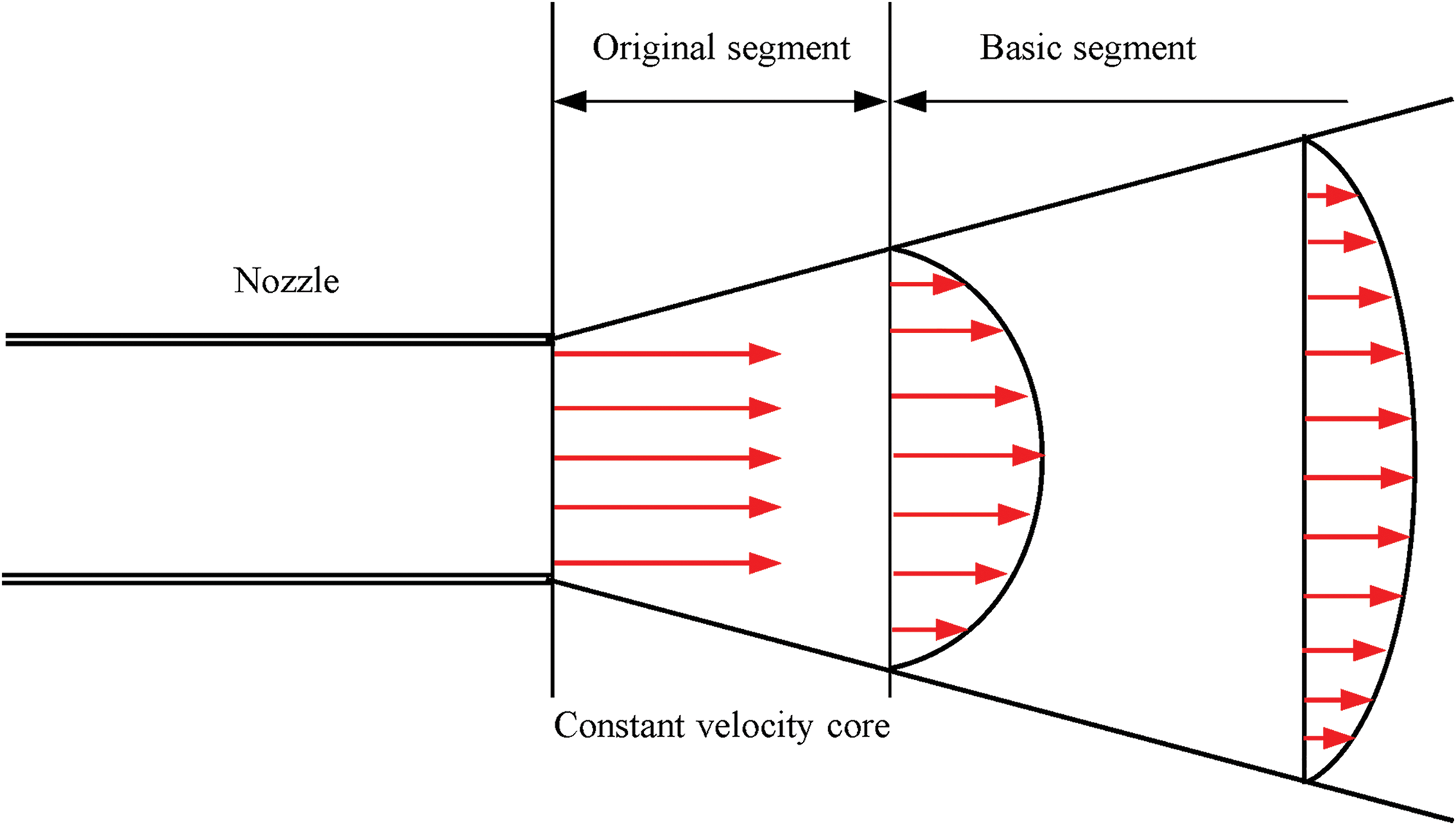
Figure 4: Jet flow structure schematic diagram
3.2 Analysis of Flow Field Characteristics
The hydraulic parameters in numerical simulations can be determined based on the operation conditions of hydraulic sandblasting perforation. Under the condition of pump pressure P = 20 MPa, the jet performance of the conical-cylindrical nozzle with flow channel structure of θ = 5°, D = 3.2 mm, L1 = 13.5 mm, L2 = 4.5 mm, R = 3.8 mm are investigated.
Fig. 5 illustrates the static pressure contour of the jet flow field, showing that the pressure starts to decrease when the jet enters the nozzle inlet. This behavior is typical as the fluid accelerates through the nozzle, leading to lower pressure in the jet as it exits, at which point the static pressure energy is converted into kinetic energy. The velocity of the abrasive particles also starts to accelerate from the contraction section of the nozzle, reaching its maximum value at the end of the contraction section. When the water jet impacts rock, the dynamic pressure energy of the jet is converted into static pressure energy as the fluid expands and decelerates after exiting the nozzle. This conversion occurs due to the turbulent mixing and interaction with the surrounding fluid, allowing the jet to exchange energy and stabilize.
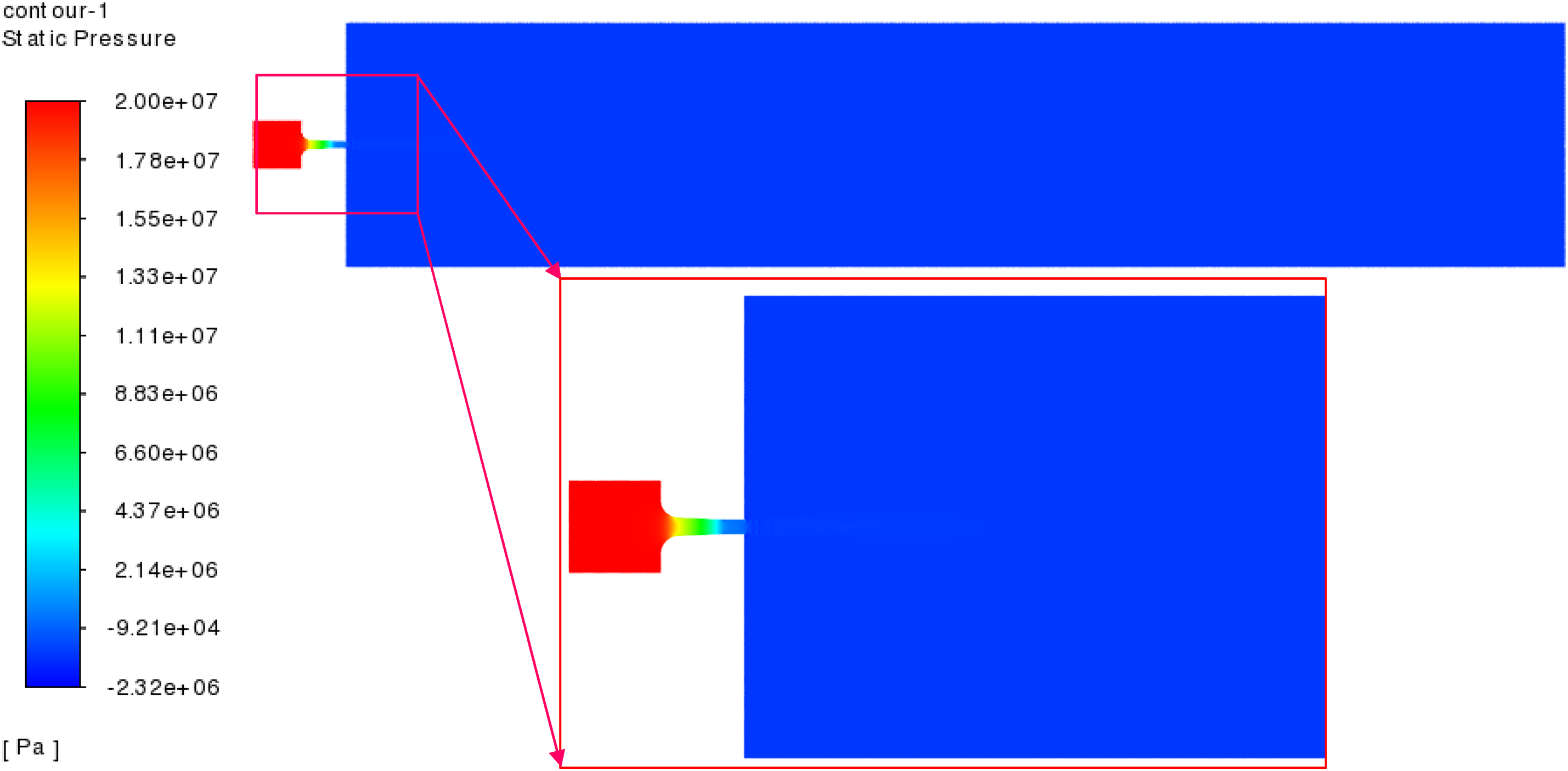
Figure 5: Flow field static pressure contour
Fig. 6 presents the velocity contour of the jet flow field. The jet velocity gradually accelerates as it passes through the nozzle, with the maximum velocity occurring at the end of the contraction section. After exiting the nozzle, the jet speed remains constant initially (constant velocity core) and then gradually decreases to zero. Meanwhile, the velocity distribution of the jet flow is consistent with the structural characteristics of the nozzle jet shown in Fig. 4. The maximum velocity of the jet flow is 200 m/s, located at the end of the contraction section, where there is a sudden change in the internal diameter of the nozzle. As the jet leaves the nozzle outlet, it encounters shear forces from the surrounding external fluid, resulting in a gradual decrease in velocity from the centerline of the jet towards the outer regions. This shear interaction promotes mixing between the jet and the ambient fluid, contributing to the dispersion of the jet and a smooth transition from the high-velocity core to the slower-moving surrounding fluid.
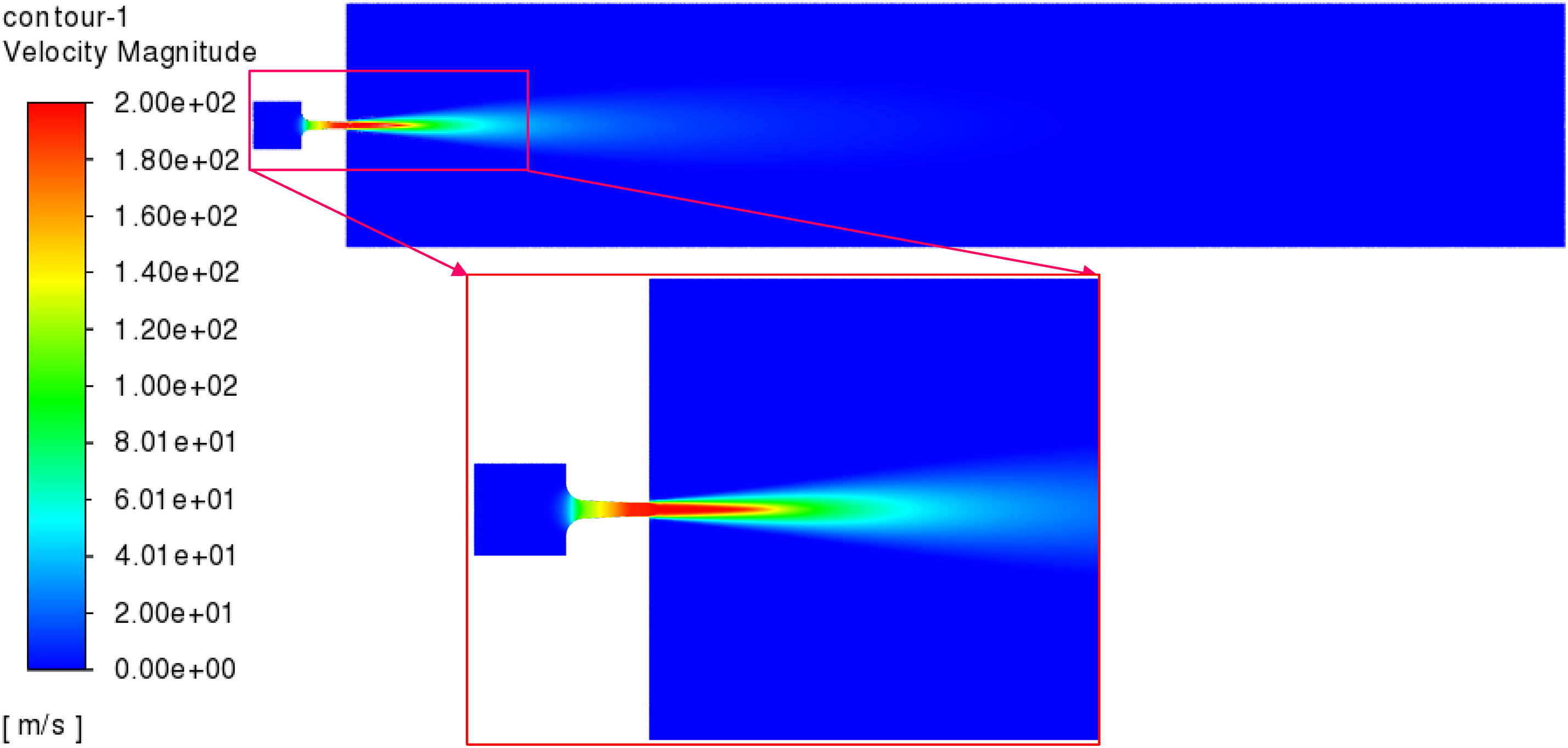
Figure 6: Flow field velocity contour
Fig. 7 illustrates the velocity distribution of the jet along the radial direction at different positions from the nozzle exit. From the figure, it is evident that the farther the position is from the nozzle exit along the axis line, the lower the jet velocity becomes. When the jet leaves the nozzle, it interacts with the surrounding fluid, creating shear forces that mobilize the adjacent stationary fluid. Consequently, the jet gradually diffuses radially, while the velocity along the axial direction decreases gradually.
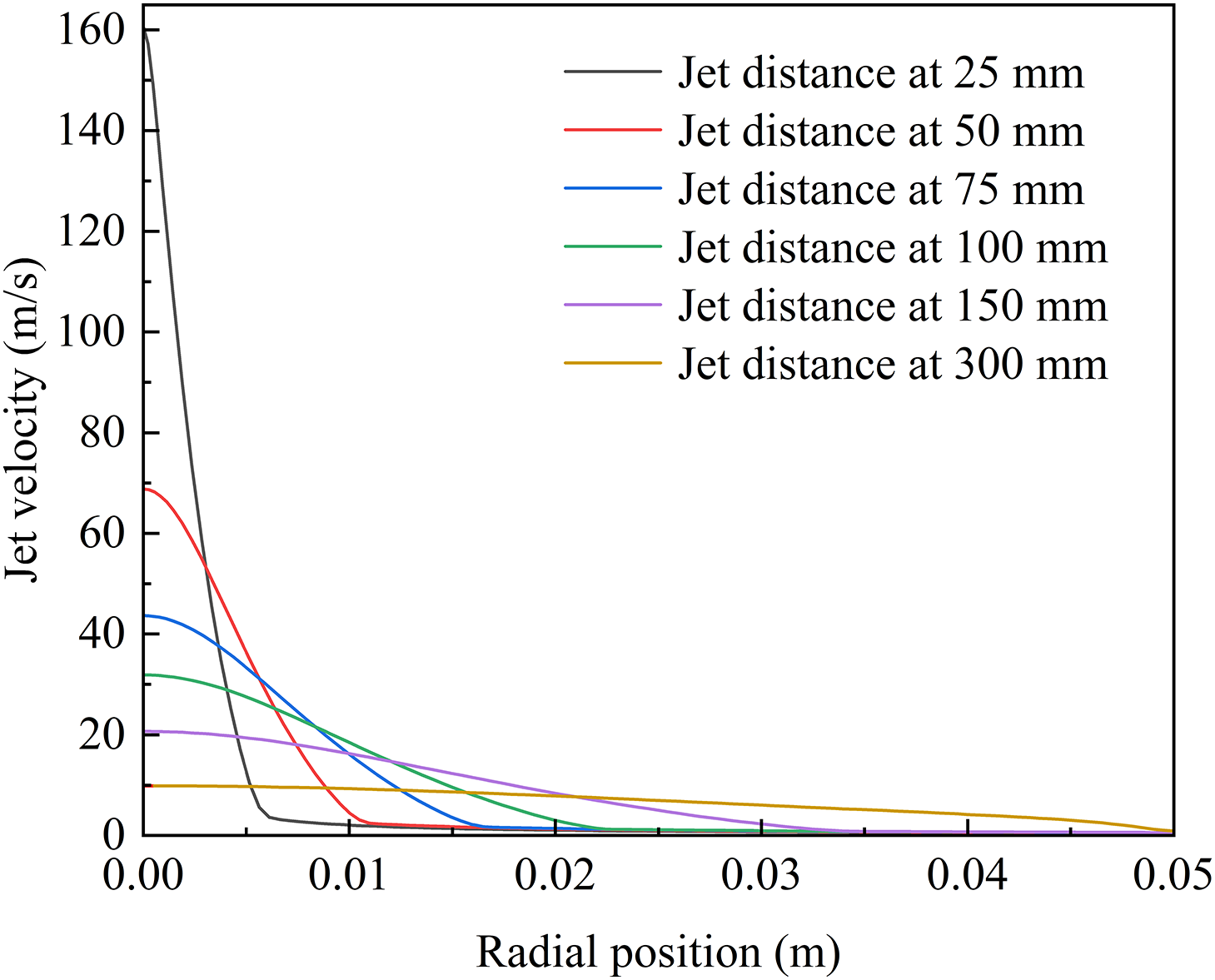
Figure 7: Jet velocity distribution along radial direction at different jet distance
In the hydraulic sandblasting perforation operations, it is essential to determine the appropriate pump pressure based on reservoir characteristics. In the calculations, keeping the nozzle structure unchanged (θ = 5°, D = 3.2 mm, L1 = 13.5 mm, L2 = 4.5 mm, R = 3.8 mm), varying the pump pressure to analyze the effect of pump pressure on the characteristics of the flow field. The influence of pump pressure on the flow field characteristics is obtained, as shown in Fig. 8.
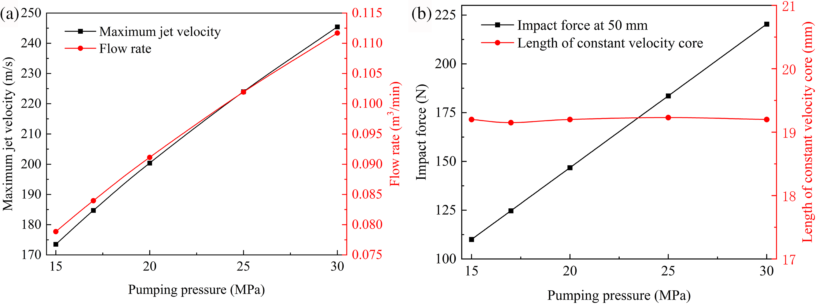
Figure 8: Influence of pump pressure on the flow field characteristics: (a) change rule of maximum jet velocity and flow rate; (b) impact force at 50 mm and length of constant velocity core
Fig. 8a presents how the maximum velocity and flow rate of the jet flow change with varying pump pressures. The results show that as the pump pressure increases, both the maximum jet velocity and the flow rate exhibit linear growth. However, a larger flow rate will consume more fluid and abrasives. In perforation operations, it is recommended to select a low flow rate nozzle while ensuring that jet velocity meets the conditions for rock breaking, in conjunction with the allowable pump pressure of the surface equipment.
Fig. 8b shows the variation of impact force at 50 mm and length of constant velocity core with different pump pressure. It can be observed that as the inlet pressure increases, the impulse force at the jet distance of 50 mm exhibits linear growth. However, the length of the constant velocity core remains essentially unchanged. Under different pump pressure, the length of constant velocity core is all approximately 19.2 mm, which is about 6 times the nozzle diameter (L = 6D).
Fig. 9 illustrates the velocity distribution of the jet along the axial direction and radial direction at jet distance of 50 mm under different pump pressure. It can be observed that the kinetic energy gained by the jet increases rapidly after acceleration within the nozzle, enabling greater rock-breaking depth. For jet nozzles with identical structures, a higher pump pressure leads to a greater flow rate, allowing it to achieve greater kinetic energy. Consequently, this results in corresponding increases in the depth and diameter of the perforated holes. This indicates that reasonable control of pump pressure and flow rate is crucial for enhancing the effectiveness of hydraulic perforation operations.
Figure 9: Jet velocity distribution along axial direction (a) and radial direction at jet distance of 50 mm (b) under different pump pressure
4 Optimization Design of Conical-Cylindrical Nozzle Geometric Parameters
The jet performance of nozzle is greatly influenced by its geometric parameters. Designing these parameters reasonably is crucial for ensuring efficient perforation while minimizing energy consumption. This research utilizes the orthogonal experimental method to optimize the nozzle’s structure, providing theoretical instruction for the flow channel design of conical-cylindrical nozzles. The orthogonal experiment is a highly efficient experimental design method that allows for the evaluation of the influence of various factors with a limited number of tests. This approach not only saves time and effort but also helps identify the optimal combination of factor levels. The range analysis method can confirm the order of various factors on the test indicators. In this study, the length of constant velocity core serves as the evaluating indicator.
In the optimization design of nozzle structures, the cylindrical segment diameter is set as a fixed value based on the flow rate requirements for perforation operations. The four factors that evident influence the jet performance of the nozzle is nozzle contraction angle θ, contraction segment length L1, cylindrical segment length L2, and fillet radius R. Each factor is set at three levels, using L9 (34) orthogonal table and referring to the field operation experience to determine the order of main factors.
Table 1 shows the detailed factors settings and the results of the orthogonal analysis under a pump pressure of 20 MPa. Numerical simulations of various geometric structures are carried out based on the orthogonal experimental design. The flow channel structure of the conical-cylindrical nozzle is optimized to achieve the best jet performance. The results indicate that the order of main factors influencing the length of constant velocity core are: L2 > θ > L1 > R. Meanwhile, the flow channel structure of the conical-cylindrical nozzle is preliminarily optimized: the cylindrical segment diameter is 3.2 mm, the contraction angle is 12°, the contraction segment length is 8 mm, the cylindrical segment length is 6.4 mm, and the fillet radius is 2 mm.
In this study, the CFD method is employed to is employed to calculate turbulent flow field under submerged conditions. The orthogonal experimental method is then used to optimize the nozzle’s structural parameters. Both the nozzle geometry and pump pressure are found to significantly impact jet performance, especially in terms of jet impact force, jet velocity, and length of the constant velocity core.
The order of main factors influencing the length of the constant velocity core are cylindrical segment length > contraction angle > contraction segment length > fillet radius. Meanwhile, the flow channel structure of the conical-cylindrical nozzle is preliminarily optimized: cylindrical segment diameter is 3.2 mm, the contraction angle is 12°, the contraction segment length is 8 mm, the cylindrical segment length is 6.4 mm, and the fillet radius is 2 mm. The simulation results can serve as a theoretical basis for future hydraulic sandblasting rock-breaking experiments, and further optimization of nozzle structure parameters can be achieved through experimental studies.
Acknowledgement: None.
Funding Statement: The authors gratefully acknowledge the financial support by the National Natural Science Foundation of China (No. 52405272), the CNOOC’s major project during the 14th Five-Year Plan period “Key Technologies and Equipment for Measurement, Recording, and Testing—Development and Engineering of Integrated Perforation Technology Equipment Based on Reservoir Geology” and the National Science Foundation of Jiangsu Province (No. BK20220533).
Author Contributions: The authors confirm contribution to the paper as follows: study conception and design: Weili Liu; data collection: Aihua Tao; analysis and interpretation of results: Chao Li and Zhijun Jie; draft manuscript preparation: Yong Zhang and Xing Chen. All authors reviewed the results and approved the final version of the manuscript.
Availability of Data and Materials: The data that support the findings of this study are available from the corresponding author upon reasonable request.
Ethics Approval: Not applicable.
Conflicts of Interest: The authors declare no conflicts of interest to report regarding the present study.
References
1. Ahmed U, Meehan D. Unconventional oil and gas resources: exploitation and development. Boca Raton, FL, USA: CRC Press; 2016. doi:10.1002/9781119213383.ch3. [Google Scholar] [CrossRef]
2. Dotson T, Farr J, Findley E. Advances in sand jet perforating. In: SPE Rocky Mountain Petroleum Technology Conference/Low-Permeability Reservoirs Symposium, 2009 Apr; Denver, CO, USA; p. 14–6. doi:10.2118/123569-MS. [Google Scholar] [CrossRef]
3. Barati R, Liang J. A review of fracturing fluid systems used for hydraulic fracturing of oil and gas wells. J Appl Polym Sci. 2014;131(16):40735. doi:10.1002/app.40735. [Google Scholar] [CrossRef]
4. Davarpanah A, Shirmohammadi R, Mirshekari B. Analysis of hydraulic fracturing techniques: hybrid fuzzy approaches. Arab J Geosci. 2019;12(13):402. doi:10.1007/s12517-019-4567-x. [Google Scholar] [CrossRef]
5. Zhou F, Su H, Liang X, Meng L, Yuan L, Li X, et al. Integrated hydraulic fracturing techniques to enhance oil recovery from tight rocks. Pet Explor Dev. 2019;46(5):1065–72. doi:10.1016/S1876-3804(19)60263-6. [Google Scholar] [CrossRef]
6. Moradi A, Tokhmechi B, Rasouli V, Fatehi Marji M. A comprehensive numerical study of hydraulic fracturing process and its affecting parameters. Geotech Geol Eng. 2017;35(3):1035–50. doi:10.1007/s10706-017-0159-2. [Google Scholar] [CrossRef]
7. Wang X, Tang M, Du X, Zhang F, Hou B. Three-dimensional experimental and numerical investigations on fracture initiation and propagation for oriented limited-entry perforation and helical perforation. Rock Mech Rock Eng. 2023;56(1):437–62. doi:10.1007/s00603-022-03069-2. [Google Scholar] [CrossRef]
8. Gao Y, Xu Z, Shen K. Jet characteristics and optimization of a cavitation nozzle for hydraulic fracturing applications. Fluid Dynam Mat Process. 2024;20(1):179–92. doi:10.32604/fdmp.2023.030499. [Google Scholar] [CrossRef]
9. Zang D, Wu S, Huang Z. Optimization design of hydraulic sandblasting perforators based on discrete phase model. China Mech Eng. 2018;29(17):2073–80. [Google Scholar]
10. Sheng M, Huang Z, Tian S, Zhang Y, Gao S, Jia Y. CFD analysis and field observation of tool erosion caused by abrasive waterjet fracturing. Pet Sci. 2020;17(3):701–11. doi:10.1007/s12182-020-00425-1. [Google Scholar] [CrossRef]
11. Gao Y, Xu Z, Shen K, Wu S. Jet characteristics and optimal design of hydraulic perforating nozzles for natural gas hydrate reservoirs. Adv Mech Eng. 2023;15(9):47. doi:10.1177/16878132231197488. [Google Scholar] [CrossRef]
12. Pan Y, Geng Z, Yuan H, Zhai S, Huo F. Numerical simulation and flow field analysis of porous water jet nozzle based on fluent. Appl Sci. 2024;14(16):7075. doi:10.3390/app14167075. [Google Scholar] [CrossRef]
13. Xu Y, Li Y. Numerical simulation of hydraulic perforating nozzles with different flow channel shapes. China Urban Econ. 2011;9:155. [Google Scholar]
14. Wen J, Qi Z, Behbahani S, Pei X, Iseley T. Research on the structures and hydraulic performances of the typical direct jet nozzles for water jet technology. J Braz Soc Mech Sci Eng. 2019;41(12):1–12. doi:10.1007/s40430-019-2075-2. [Google Scholar] [CrossRef]
15. He L, Liu Y, Shen K, Yang X, Ba Q, Xiong W. Numerical research on the dynamic rock-breaking process of impact drilling with multi-nozzle water jets. J Pet Sci Eng. 2021;207(2):109145. doi:10.1016/j.petrol.2021.109145. [Google Scholar] [CrossRef]
16. Ge Z, Zhong J, Zhang J, Wang Y, Lvu Y, Zhang S. Structural optimization of slotting nozzle used to improve coal-seam permeability. Appl Sci. 2020;10(2):699. doi:10.3390/app10020699. [Google Scholar] [CrossRef]
17. Liu Y, Zhang J, Wei J, Liu X. Optimum structure of a laval nozzle for an abrasive air jet based on nozzle pressure ratio. Powder Technol. 2020;364:343–62. doi:10.1016/j.powtec.2020.01.086. [Google Scholar] [CrossRef]
18. Katz A, Sankaran V. Mesh quality effects on the accuracy of CFD solutions on unstructured meshes. J Comput Phys. 2011;230(20):7670–86. doi:10.1016/j.jcp.2011.06.023. [Google Scholar] [CrossRef]
19. Bush W, Krishnamurthy L. Asymptotic analysis of the fully developed region of an incompressible, free, turbulent, round jet. J Fluid Mech. 1991;223:93–111. doi:10.1017/S0022112091001350. [Google Scholar] [CrossRef]
20. Yanaida K. Characteristics of water jets. Rev High Press Sci Technol. 1996;5(2):98–102. doi:10.4131/jshpreview.5.98. [Google Scholar] [CrossRef]
21. Wilcox D. Turbulence modeling-an overview. In: 39th Aerospace Sciences Meeting and Exhibit, 2001; Reno, NV, USA. [Google Scholar]
22. Duraisamy K, Iaccarino G, Xiao H. Turbulence modeling in the age of data. Annu Rev Fluid Mech. 2019;51(1):357–77. doi:10.1146/annurev-fluid-010518-040547. [Google Scholar] [CrossRef]
23. Lodefier K, Merci B, De Langhe C, Dick E. Transition modelling with the SST turbulence model and an intermittency transport equation. J Therm Sci. 2004;13(3):220–5. doi:10.1007/s11630-004-0035-2. [Google Scholar] [CrossRef]
Cite This Article
 Copyright © 2025 The Author(s). Published by Tech Science Press.
This work is licensed under a Creative Commons Attribution 4.0 International License , which permits unrestricted use, distribution, and reproduction in any medium, provided the original work is properly cited.
 Downloads
 Citation Tools