
 Submit a Paper
 Propose a Special lssue
 Open Access
REVIEW

Experimental Advances in Airfoil Dynamic Stall and Transition Phenomena
Ship and Maritime College, Guangdong Ocean University, Zhanjiang, 524005, China
* Corresponding Author: Dapeng Zhang. Email:
Fluid Dynamics & Materials Processing 2025, 21(4), 697-739. https://doi.org/10.32604/fdmp.2025.061829
Received 04 December 2024; Accepted 26 February 2025; Issue published 06 May 2025
 View Full Text
 Download PDF
Abstract
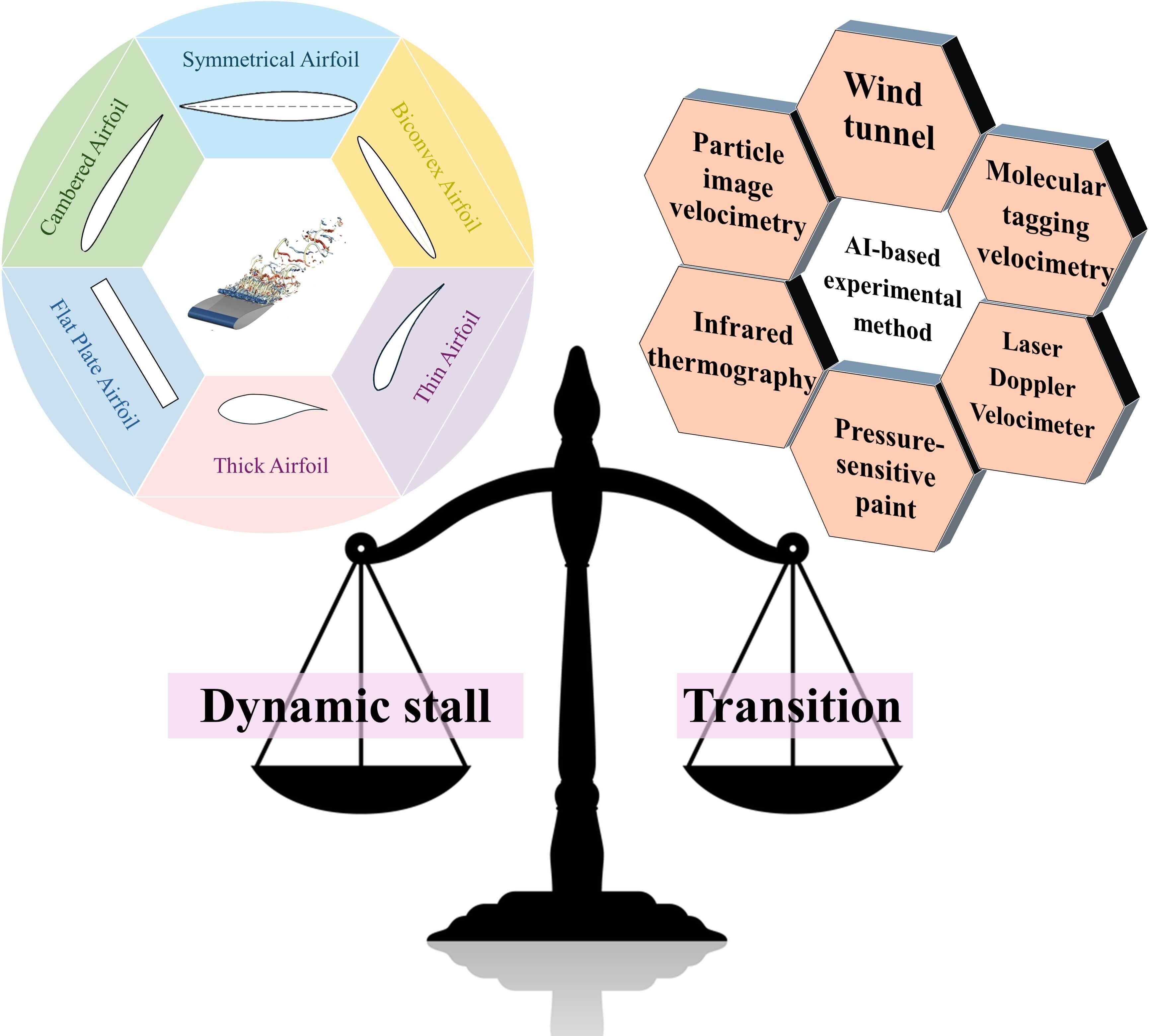
Airfoil structures play a crucial role across numerous scientific and technological disciplines, with the transition to turbulence and stall onset remaining key challenges in aerodynamic research. While experimental techniques often surpass numerical simulations in accuracy, they still present notable limitations. This paper begins by elucidating the fundamental principles of transition, dynamic stall, and airfoil behavior. It then provides a systematic review of six major experimental methodologies and examines the emerging role of artificial intelligence in this domain. By identifying key challenges and limitations, the study proposes strategic advancements to address these issues, offering a foundational framework to guide future research in airfoil structures and related fields.Graphic Abstract
Keywords
Throughout human history, continuous innovations in mechanical structures have enabled us to explore, research, and develop uncharted territories [1,2]. The airfoil structure, renowned for its unique hydrodynamic properties and high-efficiency performance [3–5], has found widespread application across diverse fields, including aerospace [6,7], ocean engineering [8,9], civil engineering [10,11], vehicle engineering [12,13], energy power engineering [14,15], chemical engineering [16,17], and biomedical engineering [18,19]. Its excellent hydrodynamic properties and broad application potential make the airfoil structure a crucial element for technological innovation in many fields, further advancing economic [20,21], societal [22,23], and scientific [24,25] development.
In recent years, research on transition and dynamic stall phenomena in wing structures has gained significant attention. As illustrated in Fig. 1, the intensity of these research hotspots has been steadily increasing. Transition and dynamic stall can lead to airfoil structure failure [26–29], resulting in significant negative impacts such as economic losses and casualties, as depicted in Fig. 2.
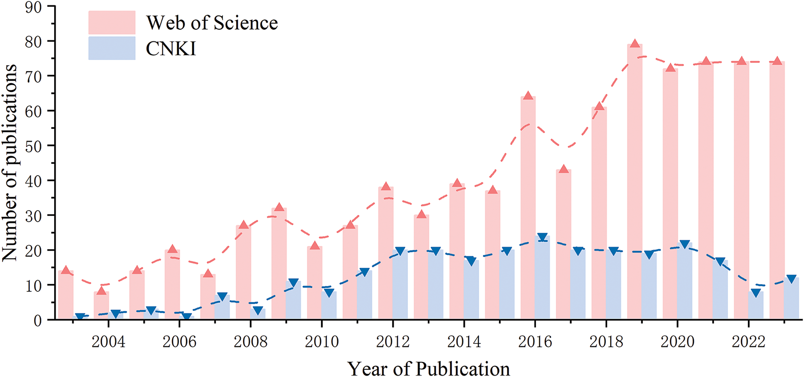
Figure 1: The number of published results about “TS = (Airfoil AND (Experiment OR Test) AND (Dynamic stall OR Transition))” in the Web of Science and CNKI, from 2003–2023
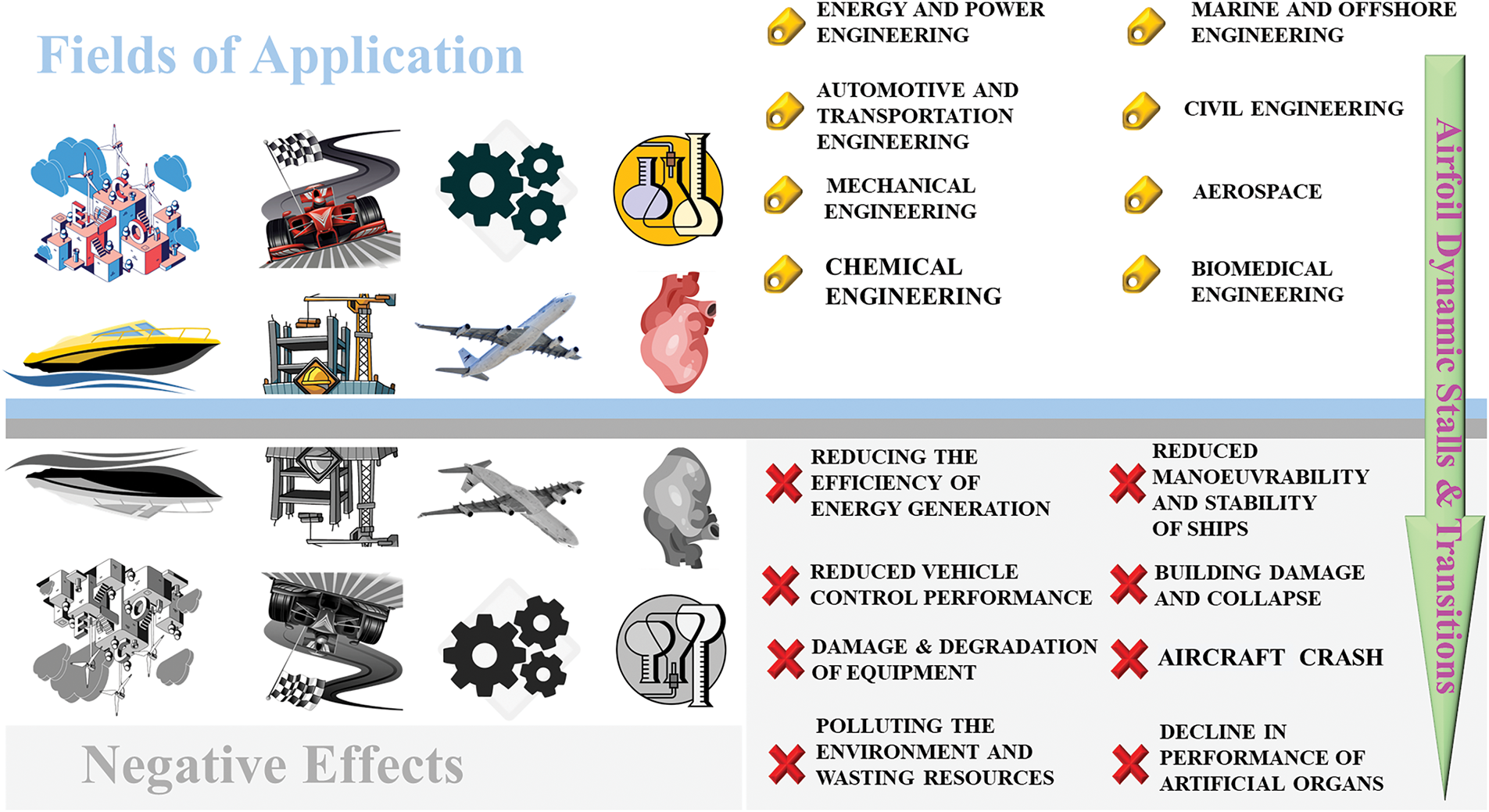
Figure 2: Areas of application of the structure of airfoils and the negative effects caused by dynamic stalling and transition
Given the importance of these phenomena, their study is crucial. Traditional experimental methods are often hindered by high costs [30,31]. Consequently, researchers have predominantly turned to numerical simulation techniques [32–34]. Common numerical simulation methods and turbulence models are shown in Fig. 3. However, numerical methods come with their own challenges, including computational errors [35,36], results validation challenges [37,38], and issues with model convergence [39,40]. Thus, it is vital to develop sustainable experimental methods that are more cost-effective, accurate, and efficient.
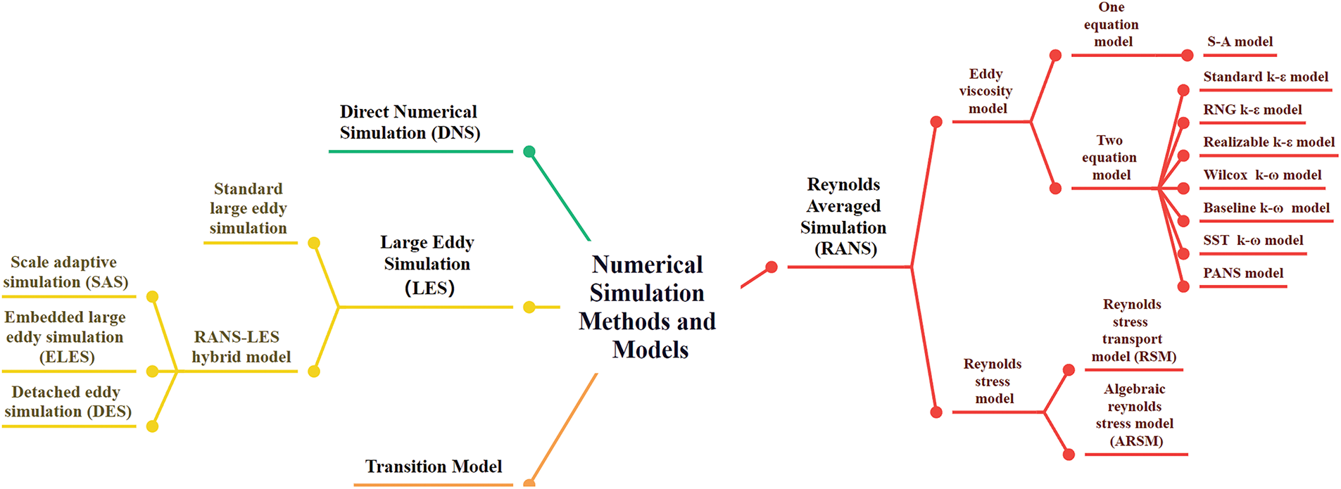
Figure 3: Common numerical simulation methods and turbulence models
To advance the field, this paper provides a comprehensive review of relevant research. It begins with definitions of transition, dynamic stall, and airfoil structure. The paper then examines six primary experimental techniques. Additionally, it explores the potential applications of artificial intelligence in this domain. Through this review, the paper identifies key limitations and challenges within the field and offers developmental suggestions to address these issues. This paper aims to serve as a valuable guide for the future development of the field. The flowchart outlining the structure of this paper is illustrated in Fig. 4.
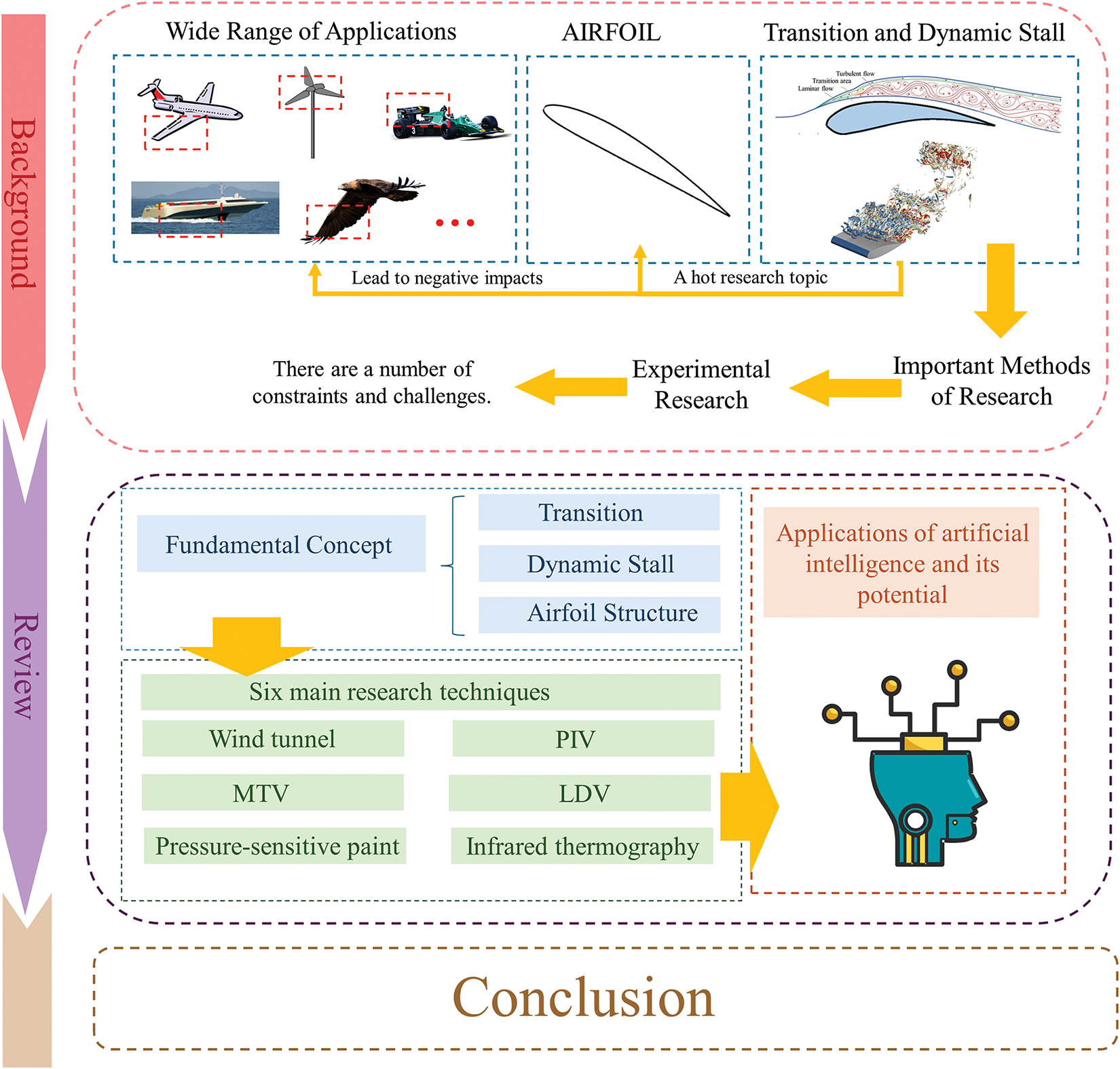
Figure 4: Flowchart of the article
Transition refers to the change in fluid flow from laminar to turbulent. The transition phenomenon of an airfoil fundamentally occurs when fluid perturbations cannot be effectively attenuated or suppressed by the laminar flow structure in the boundary layer. When external disturbances (such as surface roughness, airflow pulsations, or changes in the angle of attack) or inherent instabilities (such as high Reynolds number) induce small perturbations in the fluid flow, and these perturbations cannot be dissipated by the fluid’s viscous effects or other inherent mechanisms, they gradually amplify within the boundary layer. This leads to the transformation of laminar flow into turbulence, thereby triggering the transition phenomenon. In essence, transition is a process where the flow pattern undergoes a dramatic change due to the instability of the fluid’s internal structure in response to external perturbations. The flow transitions from a smooth, orderly laminar state to a chaotic, turbulent state [41–44]. The flow progression from laminar to turbulent flow is illustrated in Fig. 5. In order to demonstrate the fundamental concepts of the transition process, three common transition models are selected here for derivation.
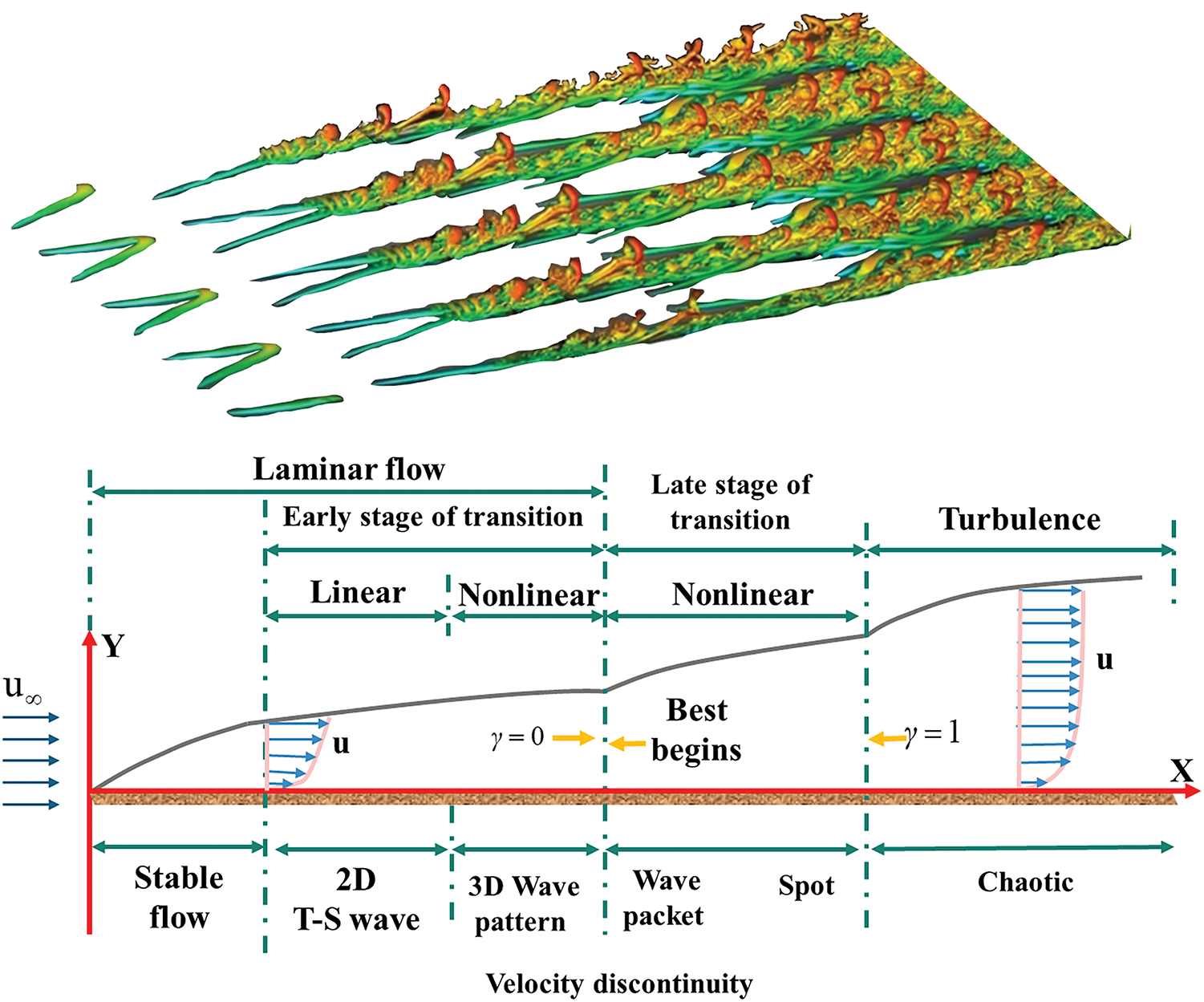
Figure 5: The progression of flow from laminar to turbulent flow
(1) Michel transition criterion
The Michel Transition Criterion is an empirical method for predicting the transition from laminar to turbulent flow in a boundary layer [45]. This criterion is an empirical model used to describe the transition of the boundary layer from laminar to turbulent flow, primarily based on the Reynolds number and fluid perturbation excitation. It posits that when the Reynolds number exceeds a critical threshold, the boundary layer undergoes a transition to turbulence. This criterion highlights the importance of velocity gradients and instabilities in the transition process, suggesting that external perturbations (such as surface roughness or flow disturbances) induce small perturbations in the boundary layer, which gradually amplify and lead to turbulence. Proposed by the German fluid mechanist Wolfgang O. Michel in the 1930s, this criterion is expressed through the following formula.
In this context,
(2)
The
The
where Pγ1 and Pγ2 are the generating terms of γ. Eγ1 and Eγ2 are the dissipation terms of γ. μ is the laminar viscosity coefficient. μt is the turbulence viscosity coefficient. σf is a constant of the turbulence model (generally taken as 1.0) [50]. Uj is the flow velocity component.
where S is the mode of strain rate, Ω is the mode of vorticity, Flength is the empirical relational coefficient controlling the length of the transition zone, Fturb restricts the action of P
where y is the distance from the wall along the outer normal direction, k is the turbulent kinetic energy,
The length of the transition region is controlled by Flength and
where D1 = −120.656 × 10⁻⁴, D2 = 868.230 × 10⁻⁶, D3 = −696.506 × 10⁻⁶, D4 = 174.105 × 10⁻¹².
The transport equation for the transition momentum thickness Reynolds number is expressed as follows:
where
where Fθt is the transition factor, which indicates the probability or degree of occurrence of a transition.
where fwake is the trailing function, which represents the impact of the trailing zone.
(3) γ-transition model
The γ-transition model is another numerical approach used to simulate laminar-to-turbulent transition processes. The method is fundamentally based on quantifying the transition from laminar to turbulent flow by defining the start and end points of the transition, typically determined by the critical Reynolds number or other flow parameters. At the core of the model is the use of a γ function, which represents the flow’s transition state and captures the nonlinear characteristics of the flow as it shifts from laminar to turbulent. By calculating the propagation of disturbances in the boundary layer, the γ-transition model can predict the transition process. It is often used in conjunction with turbulence models, such as the k-ε model, to enhance the accuracy of flow analysis. Compared to the γ-Reθ transition model, the γ-transition model is more simplified, requiring only the transport equation for the intermittency factor (γ) to be solved, without the need for the additional transport equation for the Reynolds number of momentum thickness at the start of the transition (
The transport equation for the intermittency factor:
where:
Conventional dynamic stall is an aerodynamic stall phenomenon caused by a rapid change in the angle of attack under non-constant aerodynamic conditions. When the angle of attack of an airfoil increases rapidly, the pressure distribution on the airfoil changes drastically, resulting in a sudden drop in aerodynamic forces and producing significant aerodynamic changes. Dynamic stall not only affects the aerodynamic performance of the vehicle but also can cause structural vibration and noise problems [57–60]. Fig. 6 shows an example of a dynamic stall.
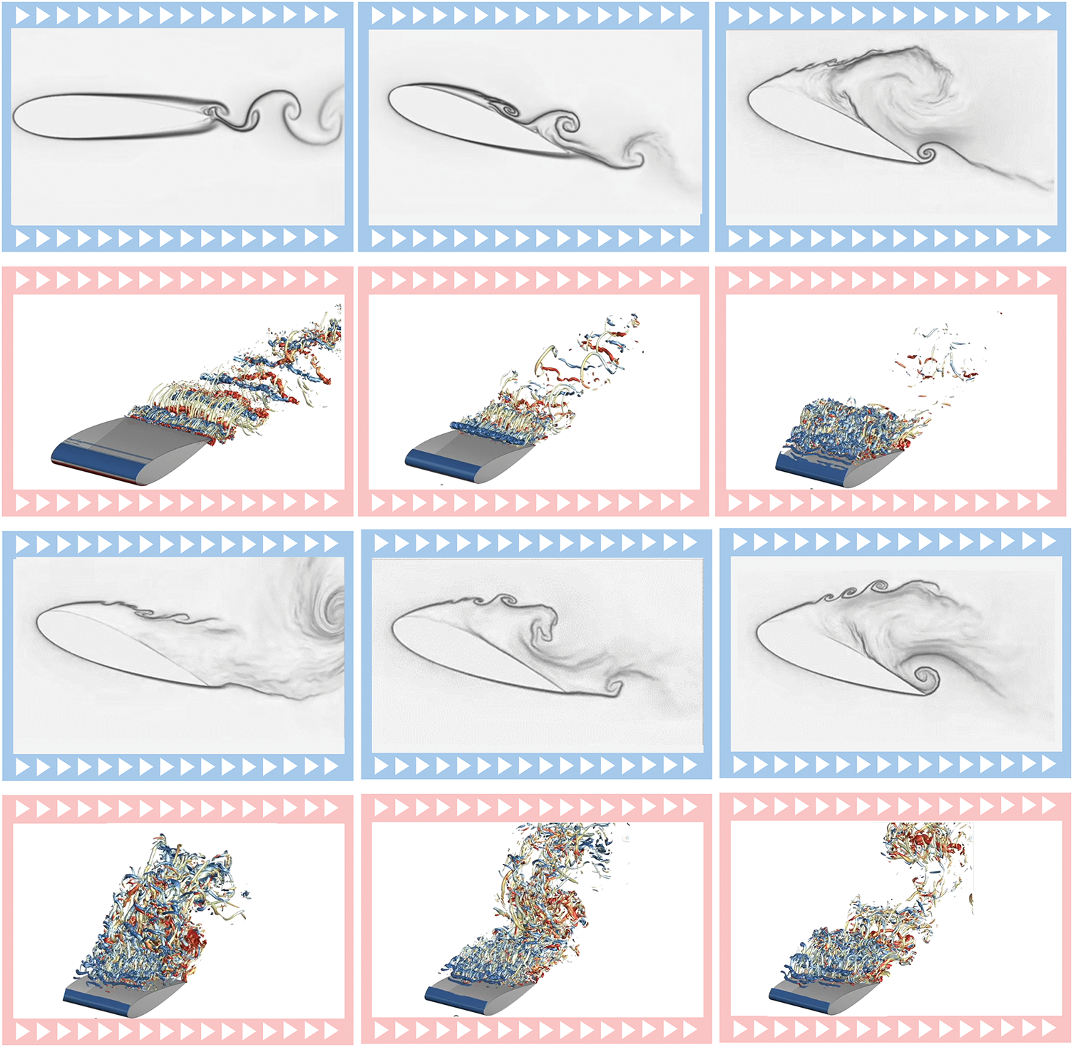
Figure 6: Examples of dynamic stalls
(1) Beddoes-Leishman model
The Beddoes-Leishman model is one of the most widely used dynamic stall models. It divides the entire dynamic stall process into three stages: attached flow, separated flow, vortex shedding, and coupling between flow separation and vortex shedding [61–63]. The Beddoes-Leishman model is used to describe the aerodynamic properties of an airfoil during dynamic stall, integrating both steady aerodynamic theory and dynamic effects. The model applies conventional aerodynamic theories of constant lift and drag at small angles of attack, while accounting for vortex separation and dynamic stall phenomena at larger angles of attack. During the dynamic stall process, the airflow experiences non-steady conditions, such as instantaneous changes in angle of attack and windward velocity, leading to fluctuations in lift and aerodynamic loads. The model also incorporates the hysteresis effect to simulate the time delay in the aerodynamic response of the airfoil, particularly during the transition from steady flow to stall. This model enables accurate prediction of the aerodynamic performance and stability of dynamically loaded systems, such as rotor blades, under high-speed motion or rapid changes in angle of attack. Fig. 7 shows a schematic of the generic Leishman-Beddoes type dynamic stall model and its different modules.
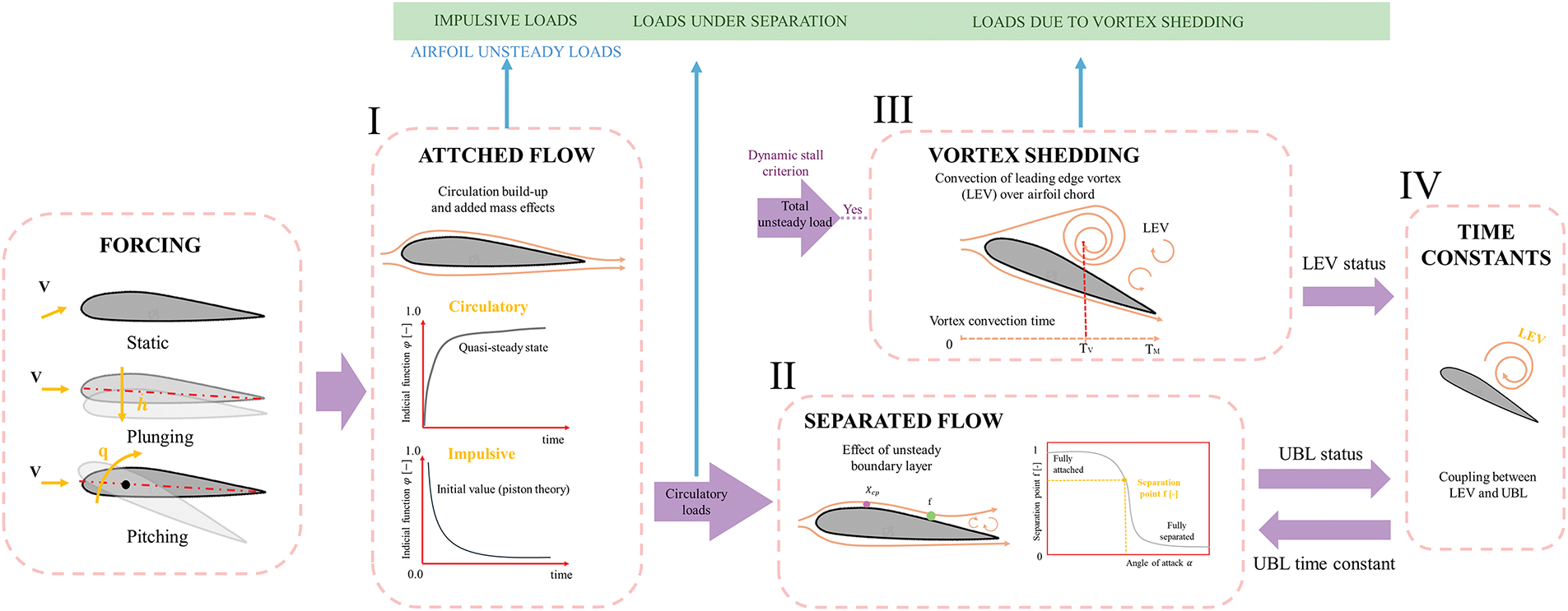
Figure 7: Schematic representation of a generic Leishman-Beddoes-type dynamic stall model and its different modules: I) attached flow module; II) separated flow module; III) vortex shedding module; IV) coupling module between flow separation and vortex shedding
In the attached flow phase, the aerodynamic forces of the airfoil can be modeled by superposition of the step responses. Total normal force coefficient corresponding to the nth step
where:
where CNa is the slope of the static normal force coefficient, M is the Mach number, TI is a time constant expressed as the ratio of the chord length of the airfoil to the local speed of sound, Δαn and Δt are the variations in the angle of attack and the time step, respectively. Xn, Yn and Dn are the defect functions describing the variations of the aerodynamic coefficients in non-constant flow conditions, and Ka is a time constant related to the Mach number.
In the separation flow phase, airflow on the upper surface of the airfoil begins to separate, leading to nonlinear changes in the lift and drag coefficients. The effects of separation flow in this phase are modeled using the Kirchhoff model and a separation point prediction model [64]. The relationship between the normal and tangential static separation points is also considered.
where α0 is the zero-lift angle of attack, and F denotes the separation point position, which is related to the wing angle of attack.
Considering the hysteresis of the leading edge pressure response [65], the effective angle of attack needs further correction:
where
The effective angle of attack:
By introducing the time constant Tf, the additional effect due to separation, based on the delay in the boundary layer, is captured using the first-order hysteresis technique according to the dynamic splitting point. This approach results in the determination of dynamic normal force coefficients and tangential force coefficients.
The vortex shedding phase accounts for the aerodynamic effects of leading-edge vortex generation and transport. The vortex-induced increment in the normal force coefficient
where the vortex normal force coefficient and vortex tangential force coefficient:
where A is the time constant.
The total normal and tangential force coefficients are obtained by summing the contributions from the attached flow, separated flow, and dynamic vortex phases.
Normal and tangential force coefficients can be converted to lift and drag coefficients.
The Beddoes-Leishman (B-L) model has evolved through several versions, each aimed at enhancing the accuracy and adaptability of dynamic stall predictions. The initial B-L model (1988) was simple and practical but lacked a detailed description of the complex flow field. The 1994 revision improved dynamic effect considerations, enabling more accurate simulation of stall characteristics for low-speed vehicles and rotors, though it still relied heavily on experimental data. The 2000 version further refined the simulation of the stall process and airflow separation, increasing the model’s adaptability but also its computational complexity. The post-2005 development integrated CFD data to improve the accuracy and reliability of the stall and airflow separation simulations. However, this enhancement came at the cost of greater computational intensity and a continued reliance on extensive experimental validation. Across all versions, while the accuracy of the model has improved, so too has the computational complexity and dependency on experimental data.
(2) ONERA model
The ONERA model is another important dynamic stall model developed by the Centre d’Études Aéronautiques (CERA), particularly suitable for applications such as rotor blades and wind turbines. It provides a comprehensive description of an airfoil’s aerodynamic characteristics across different flight phases by combining first- and second-order transfer functions. This approach enhances the accuracy and reliability of dynamic stall simulations [66–70].
The method is based on the hysteresis effect, nonlinear characteristics, and transfer function of the dynamic response of the airflow. It simulates the complex interaction between airflow and airfoil by considering rapid changes in the airfoil’s angle of attack and the effects of airflow hysteresis, particularly the stall phenomenon under large angles of attack and unsteady airflow conditions. The model incorporates nonlinear correction terms to describe the variations in lift, drag, and moment, with the model parameters calibrated using experimental data. This enables the accurate prediction of the transition process from steady lift to stall for the airfoil.
In the ONERA dynamic stall model, a set of differential equations describes the non-stationary characteristics of the airfoil during the dynamic stall process. The model coefficients are not set arbitrarily but are derived from well-designed wind tunnel experiments with small amplitude oscillations, ensuring their accuracy through a rigorous discrimination process.
In the linear region of the airfoil, before the angle of attack reaches the stall angle, the ONERA model uses a first-order transfer function to approximate aerodynamic load changes, maintaining accuracy in this phase. As the airfoil enters the stall region, where flow separation becomes more pronounced and aerodynamic changes become complex, the ONERA model employs a second-order transfer function to capture the significant time delays and over-increases associated with these nonlinear features.
Coefficient of lift:
First-order transfer function:
Second-order transfer function:
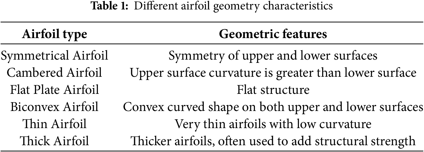
An airfoil is a streamlined object that, when oriented at the optimal angle, can deflect oncoming fluid as it moves through it [71–73]. Therefore, studying the transition and dynamic stall problems of airfoils is crucial for the design and application of airfoil structures. These structures are broadly classified into six categories based on their geometries: Symmetrical Airfoil [74,75], Cambered Airfoil [76,77], Flat Plate Airfoil [78,79], Biconvex Airfoil [80,81], Thin Airfoil [82,83], and Thick Airfoil [84,85]. Fig. 8 shows the geometry of the six airfoil structures.
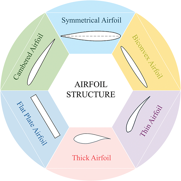
Figure 8: Geometry of six common airfoil structures
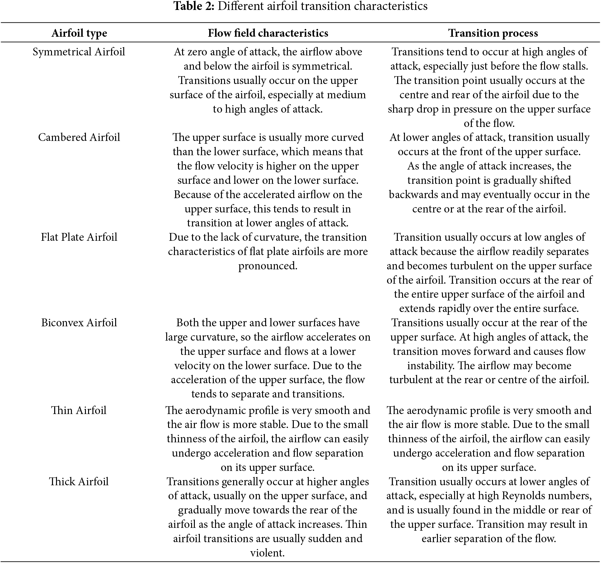
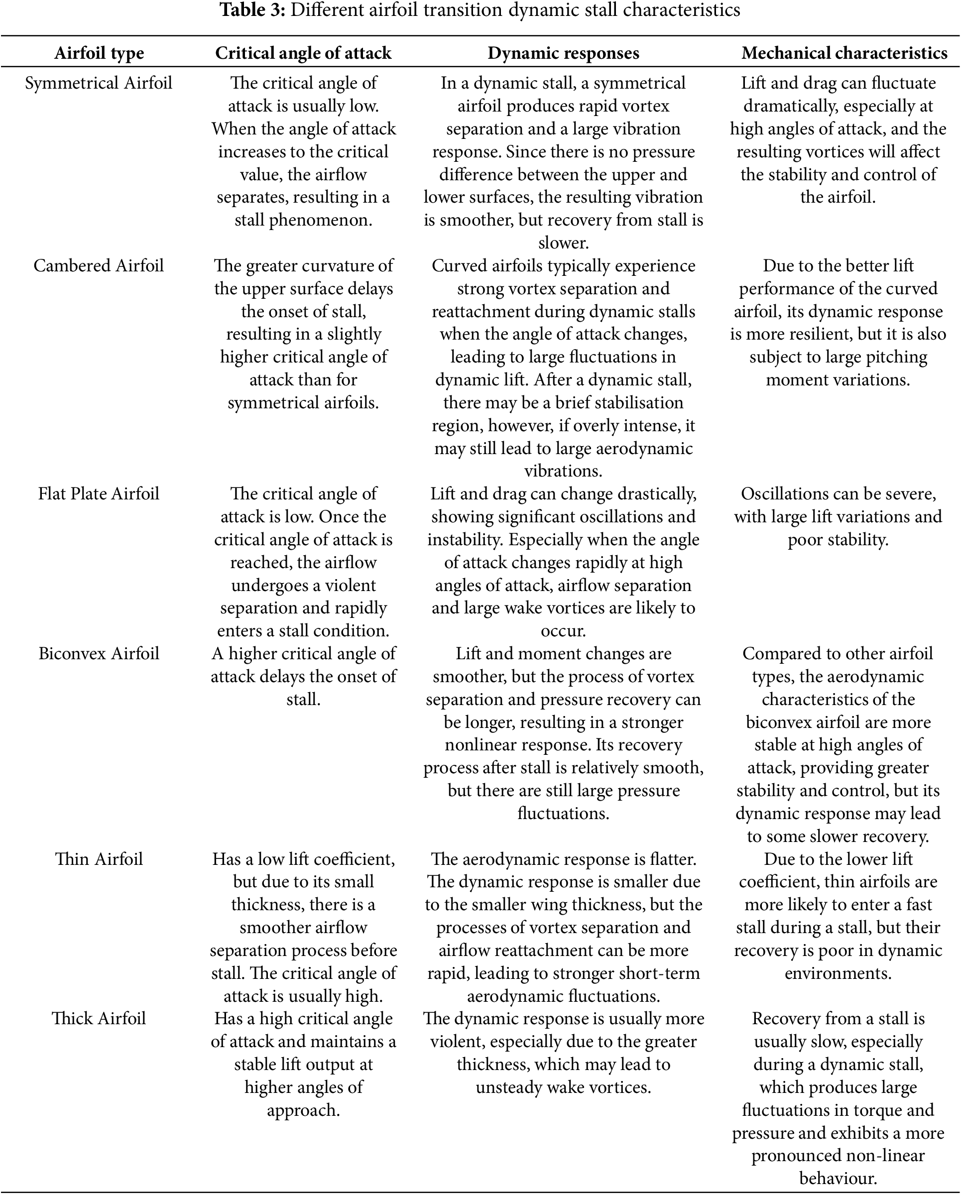
As shown in Tables 1–3, different airfoil geometries exhibit varying behaviors in transition and dynamic stall phenomena. Symmetrical airfoils demonstrate consistent performance during angle of attack changes, with stable transition positions and smooth dynamic stall. Asymmetrical airfoils tend to experience transition more readily on the upper surface, with a higher propensity for dynamic stall at high angles of attack. Flat plate airfoils are sensitive to changes in the angle of attack, showing forward transition and pronounced dynamic stall at high angles of attack. Hyperbolic airfoils maintain stable transition positions at high speeds but are prone to stall at low speeds and high angles of attack. Thin airfoils exhibit significant forward transition and are prone to flow separation at high angles of attack. Thick airfoils enhance structural strength but experience forward transition, maintaining laminar flow for a longer duration at high angles of attack but suffering a sharp lift drop when stall occurs.
3 Advances in Experimental Research
Experimental wind tunnels, as ducted experimental apparatus, simulate the flow of gases around vehicles or objects by artificially generating and controlling airflow. This allows for measuring the effects of airflow on the entity and observing physical phenomena [86–89]. Wind tunnel experiments are indispensable tools in studying dynamic stall and boundary layer transition of airfoils. It provides a controlled flow environment that enables precise adjustment of flow velocity, pressure and other parameters, helping researchers to observe and analyse the details of transition and dynamic stall.
Wind tunnel experiments play a crucial role in simulating the dynamic behavior of airfoils and studying aerodynamic characteristics during dynamic stall by precisely controlling airflow parameters. Additionally, they are essential for investigating boundary layer transition in hypersonic vehicles, providing critical data for thermal protection design and performance optimization through high-resolution testing techniques [90–92].
Raus et al. measured the aerodynamic and acoustic properties of the NACA0012 airfoil by varying the angle of attack in an anechoic wind tunnel. Fig. 9 illustrates a schematic of the experimental setup points. The flow deviation in the open jet wind tunnel necessitated corrections to the effective angle of attack. However, verifying these corrections presented challenges. Additionally, capturing the complex relationship between dynamic stall and noise in this experimental setup proved to be difficult [93].
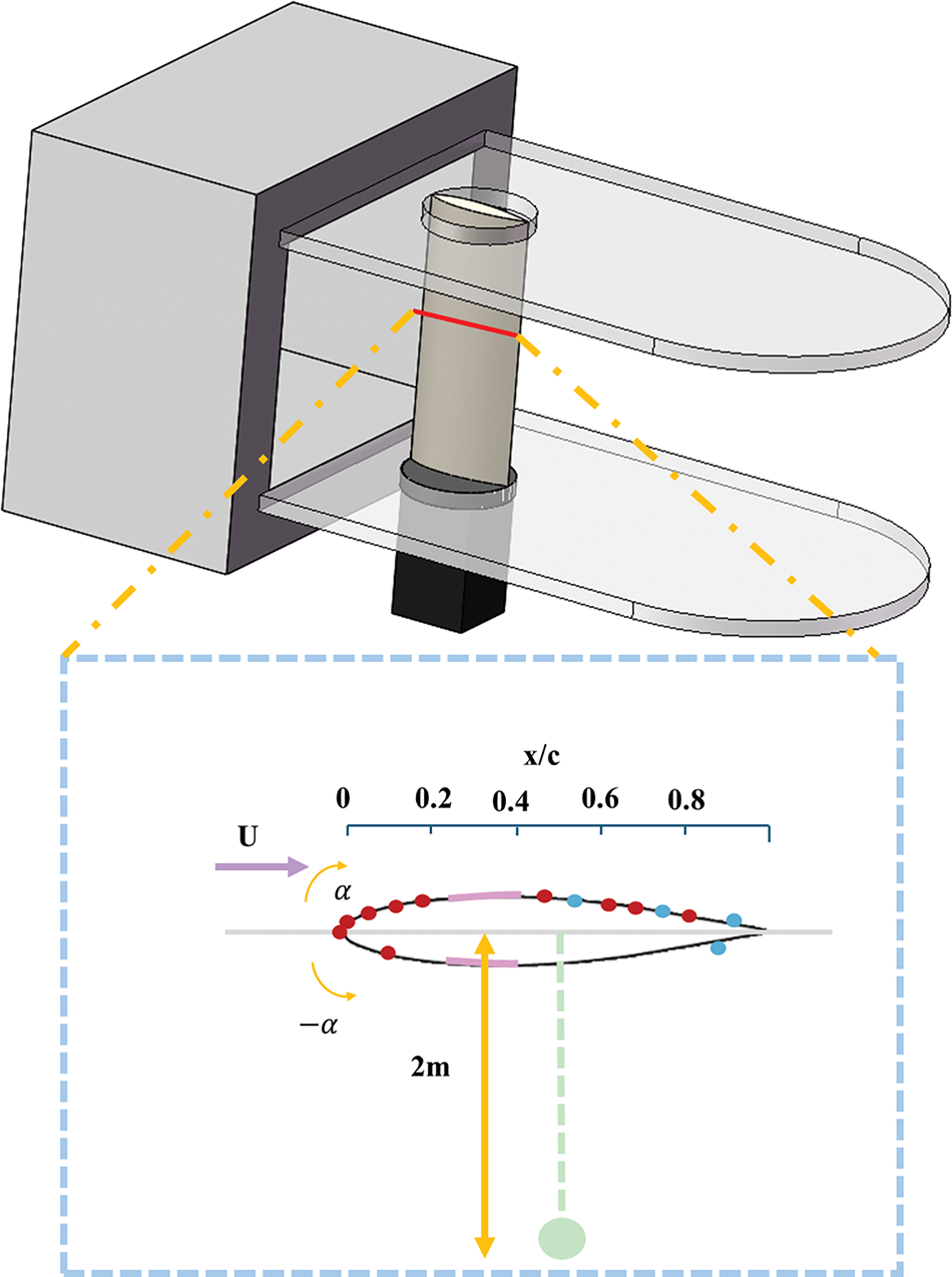
Figure 9: Schematic of the experimental setup points. Red dots and blue dots show the positions where only the steady-state surface pressure is measured and the positions where both the steady and fluctuating wall pressures are measured, respectively. The green dot shows the position of the far-field microphone. Pink areas show the positions of the tripping tape
Li et al. combined wind tunnel experiments with advanced Particle Image Velocimetry (PIV) techniques to accurately measure and visualize the aerodynamic performance and flow characteristics of a wind turbine airfoil under dynamic stall conditions. This approach provides valuable insights into the effectiveness of plasma aerodynamic drives in controlling dynamic stall and improving aerodynamic efficiency [94].
Mayer et al. used a temperature-controlled anechoic wind tunnel with Kevlar walls in their study of the aeroacoustics properties of oscillating airfoils in pre-stall and post-stall states. This setup minimized flow deflection and enabled accurate far-field noise measurements. However, the Kevlar wall test section required specific wind tunnel calibration due to its unique characteristics [95].
Zhang et al. used a wind tunnel experiment combined with force balance to measure phase-averaged and instantaneous aerodynamic loads on a pitching wing. Fig. 10 shows a schematic of the wind tunnel test section. However, the experimental setup is sensitive to errors and requires careful calibration [96].
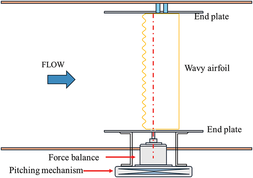
Figure 10: Schematic of the wind tunnel test section
Li et al. used a low-speed wind tunnel to investigate the effects of dust and turbulence on a vertical axis wind turbine (VAWT) related to dynamic loading and efficiency in an urban environment. Fig. 11 shows a schematic of the experimental wind tunnel. While the wind tunnel experiments were conducted in a controlled setting, this may not fully replicate the complex and variable conditions experienced by VAWTs in urban environments [97].
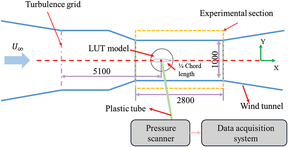
Figure 11: Schematic of experimental wind tunnel
Amandolese et al. used the S4 wind tunnel to study the effects of dynamic stall on wind turbine blades. Their wind model, based on a spectral description of turbulence, focuses on larger turbulence scales relative to the airfoil chord. However, this approach may not fully account for the effects of smaller turbulence scales, which can also impact aerodynamic performance [98].
Wang et al. conducted experiments on the unsteady vortex flow field of a typical rotor blade under dynamic stall conditions using advanced PIV techniques in an open return wind tunnel. Fig. 12 illustrates the experimental schematic and experimental flowchart. In this setup, lasers and CCD cameras were synchronized by a computer system to measure the velocity of the flow field around the rotor blade, capturing high-quality data for analysis. This comprehensive approach provided valuable insights into the aerodynamic characteristics and behavior of leading-edge vortices (LEVs) under dynamic stall conditions [99].
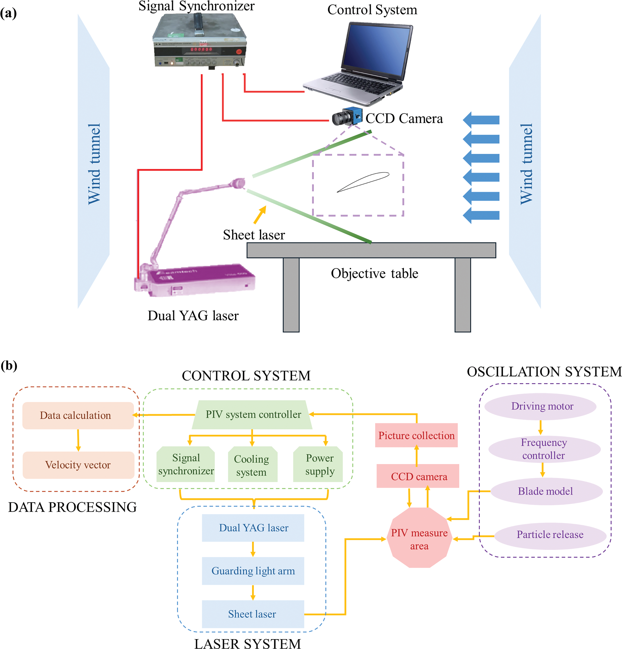
Figure 12: (a) Schematic of experiment. (b) Flowchart of experiment
To study the dynamic stall phenomenon in a vertical axis wind turbine (VAWT), Aboelezz et al. modified a low-speed wind tunnel by constructing and installing a test bed in the exit section. The test stand consists of a tower for holding the wind turbine, incorporating essential components such as torque transducers, braking systems, and pulleys. This experimental setup provides a controlled environment with comprehensive measurement capabilities, load variations, reduced fluctuations, dynamic measurements, and performance enhancements. These advantages make it an effective and reliable setup for evaluating the performance of guided blade airfoil wind turbines [100].
Phillips et al. investigated the use of sweep jets to control aerodynamic loads and prevent dynamic stalls during rapid surface deflections on the NACA 0021 wing. They employed dynamic pressure sensors in conjunction with a PSI system to synchronize flap deflection and pressure readings, ensuring accurate measurement of the flap deflection angle over time. Additionally, smoke lines were used for flow visualization, aiding in the confirmation of vortices and flow patterns around the flap [101].
Ikami et al. utilized cntTSP to measure the boundary layer transition of an oscillating airfoil in a low-speed wind tunnel. cntTSP is a flow visualization technique that combines temperature-sensitive paint (TSP) with carbon nanotubes (CNTs), which act as sprayable temperature sensors. The CNTs serve as a thin internal electrical heater for the TSPs. This technology allows for the visualization of boundary layer transition movements on moving airfoils, providing a clear depiction of the transition dynamics [102].
Quinn et al. present a new multi-purpose wind tunnel designed to generate both low- and high-turbulence conditions, facilitating advanced studies in the biomechanics and aerodynamics of animal flight. Fig. 13 shows the structure of the wind tunnel. The tunnel is powered by a low-noise 18-blade axial fan, minimizing acoustic interference in the test section. A seamless honeycomb and multiple fine mesh screens are used to straighten and reduce turbulence in the airflow before it enters the test section. The design and capabilities of this facility make it an invaluable tool for comparative biomechanical studies, aiding in the understanding of the dynamics of simulated airfoil structures of various species [103].
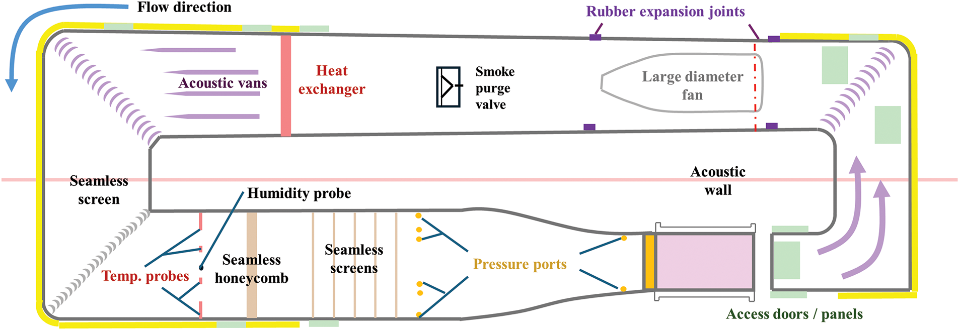
Figure 13: The closed-circuit wind tunnel uses flow conditioning to decrease turbulence and can operate in both open- and closed-jet configurations. The components of the wind tunnel are shown by color. A large diameter fan drives air through a series of flow conditioning elements, then through a contraction into the test section (pink). A heat exchanger and temperature probes (red) are used to regulate temperature in the tunnel. Airspeed is measured using static pressure ports in the stilling chamber and contraction (orange). The turning vanes and sidewalls shown in light blue and purple are filled with mineral wool to attenuate fan noise
Grogger et al. described the development, construction, and evaluation of a cost-effective open-circuit wind tunnel designed for avian flight experiments, capable of achieving the flow and turbulence levels necessary to study large birds such as the northern white-headed ibex. This research resulted from close interdisciplinary collaboration between engineers with expertise in fluid dynamics and biologists with experience in bird behavior and physiology, highlighting the importance of interdisciplinary collaboration [104].
Brunner et al. utilized a wind tunnel to study the transition from laminar to turbulent flow, the change in stall type from trailing edge to leading edge, and the behavior of flow separation and reattachment at different Reynolds numbers. Their findings showed that the presence of laminar separation bubbles can delay turbulent separation compared to natural transition flow. However, achieving high Reynolds numbers without disproportionate compressibility effects in a controlled laboratory environment remains a challenge [105].
To establish a dynamic aerodynamic evaluation model for large-scale wind turbines, an accurate experimental design is essential. To achieve the dynamic oscillatory motion of the airfoil, Li independently designed and built the experimental platform. A wind tunnel was used to simulate the real free-flow environment, and the dynamic stall test rig provided precise oscillatory motion of the airfoil. The motion control system achieved a stable angle of attack and oscillatory speed by precisely controlling the motor position. The DTC Initium pressure acquisition system enabled high-frequency collection of pressure signals from the airfoil surface, while the IFA system measured and recorded velocity and temperature signals from the flow field [106].
The advantage of these systems is that they provide accurate and reliable experimental data, facilitating the study of the dynamic stall characteristics and flow control mechanisms of wind turbine airfoils.
3.2 Particle Image Velocimetry
Particle image velocimetry (PIV) is a transient, multipoint, contactless hydrodynamic velocimetry technique. It achieves accurate measurement of the velocity distribution in the flow field by scattering tracer particles within the flow, illuminating these particles with a pulsed laser sheet, recording continuous images of the particles with a high-speed camera, and subsequently obtaining flow velocity vectors at each point through image analysis techniques. PIV combines flow visualization and image processing techniques, providing powerful flow measurement capabilities [107–110]. PIV is capable of simultaneously capturing transient changes in the entire flow field and accurately depicting complex flow structures, such as propulsion, vortex separation, and dynamic stalling processes at transition points, which makes it suitable for the dynamic study of a wide range of flow states. Fig. 14 shows an example of PIV.
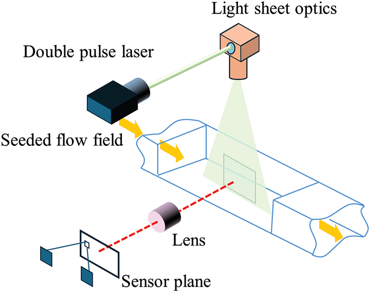
Figure 14: An example of PIV
In dynamic stall studies of airfoils, PIV is widely used to measure and analyze the non-stationary vortex field characteristics of airfoils during the dynamic stall process [111,112]. In airfoil transition studies, PIV plays a crucial role in understanding the transition mechanism and exploring effective methods to control the transition process. It measures the susceptibility of the boundary layer to external turbulence perturbations and tracks the growth path of these perturbations within the boundary layer [113,114]. These studies not only help improve the performance of airfoil structures but also provide valuable experimental data and theoretical support for the development of fluid dynamics.
Adatrao et al. explore the challenge of quantifying uncertainty in particle image velocimetry (PIV) due to systematic errors, which are often overlooked by existing methods that primarily focus on random errors. They propose a new approach using design of experiments (DOE) and analysis of variance (ANOVA) to identify key experimental factors contributing to uncertainty in PIV measurements. To evaluate this method, both planar and stereo PIV measurements were performed, as shown in Fig. 15. The proposed DOE approach effectively quantifies both random and systematic uncertainty in PIV measurements, providing a more comprehensive understanding of measurement reliability [115].
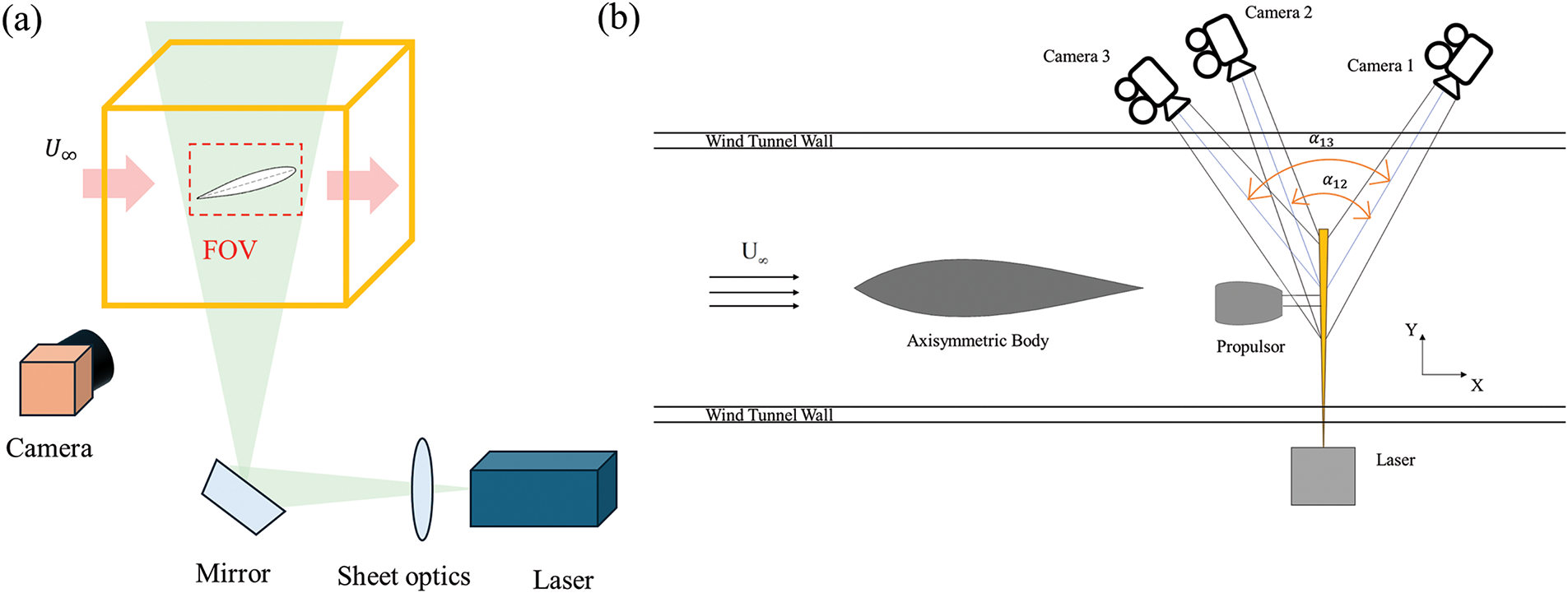
Figure 15: (a) Planar PIV measurements. (b) Stereo PIV measurements
A study by Saaid et al. investigated the use of tomographic particle image velocimetry (Tomo-PIV) to analyze the fluid dynamics of the left ventricle (LV) with different prosthetic heart valves. Fig. 16 shows an example of the Tomo-PIV. The aim was to demonstrate the feasibility of capturing three-dimensional flow in a compliant LV model and to compare the flow fields generated by different prosthetic valves under identical conditions. However, the Tomo-PIV hardware and software are more complex and expensive than 2D PIV or multiplanar scanning setups, which may pose a significant barrier to widespread adoption [116].
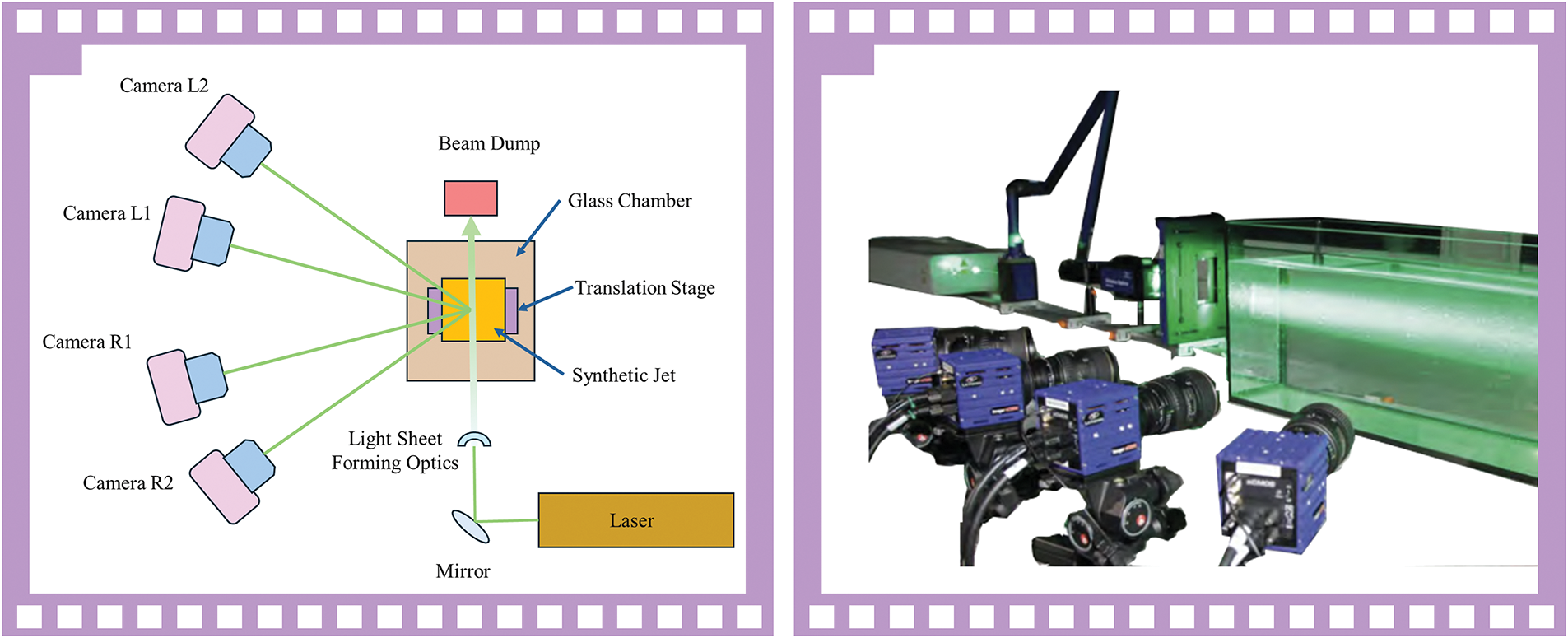
Figure 16: An example of the Tomo-PIV
Balducci et al. used particle image velocimetry (PIV) and particle tracking velocimetry (PTV) techniques to study the evolution of the flow field downstream of the prosthetic heart valve, especially in the beginning of the ascending aortic branch. These techniques are crucial for a comprehensive assessment of the effective stresses on hemocytes, with PIV providing information on the intensity of the stresses and PTV offering insights into the timing of the pressure application. Although high spatial and temporal resolution can be achieved using high-speed cameras, limitations remain. The minimum spacing between velocity vectors measured by PIV is slightly less than 1 mm, which, despite the high resolution, may not capture all the fine details of the flow field [117].
Soodt et al. utilized stereoscopic scanning PIV to experimentally study transitional bronchial velocity distributions. Their measurements revealed a complex three-dimensional velocity distribution in the bronchial bifurcation, highlighting the presence of vortices and shear layers during the respiratory cycle. This study underscores the need for advanced measurement techniques to capture the intricate flow dynamics in the respiratory system. The use of stereoscopic scanning particle image velocimetry (PIV) to capture three-dimensional, time-resolved velocity fields is a sophisticated technique that can also be applied to the study of flow around airfoils, providing detailed insights into flow behavior [118].
Van Hooff et al. experimentally analyzed transitional flows in a ventilated enclosure using a reduced-scale water-filled model to study forced mixed ventilation driven by a transitional aircraft jet. Flow visualization and PIV measurements were conducted for time-gap Reynolds numbers between 800 and 2500 to develop and validate a CFD model of the indoor flow. This methodology offers a comprehensive approach to studying transitional flows in forced mixing ventilation. The combination of downscaled experiments, PIV measurements, and flow visualization provides valuable data for the development and validation of CFD models [119].
Lang et al. used Laser Doppler Anemometry (LDA) and Stereo Particle Image Velocimetry (SPIV) to investigate controlled transition development processes in laminar separation bubbles. Their study showed that the combined use of LDA and SPIV to study controlled transition development, driven primarily by 2D Tollmien-Schlichting wave amplification, provides a detailed understanding of the unsteady and 3D rupture of the separating shear layer. The results are in good agreement with Linear Stability Theory (LST) and Direct Numerical Simulation (DNS), highlighting the minor role of stable 3D disturbances in the transition process [120].
The combined use of LDA and stereo PIV offers detailed visualization of the fluid dynamics, including the onset of 3D vortex structures and the breakdown of turbulence in the separated boundary layer, contributing to a better understanding of transition mechanisms. However, LDA-related measurement times can be long, especially in water, which may hinder the resolution of small structures when high temporal resolution is required. Additionally, LDA and PIV setups are complex and costly, posing further challenges.
Zhang et al. used a PIV system to capture detailed flow characteristics around a hydrofoil, employing a laser beam sheet and a high-resolution camera. They developed a new velocity field calculation method to minimize static mask errors and improve the accuracy of the PIV analysis. The PIV measurements provided detailed insights into the flow characteristics around pitching hydrofoils, revealing the dynamic behavior of cavitation modes and their effect on the flow field [121].
Chen et al.’s study using particle image velocimetry (PIV) explores the effect of anisotropic porous walls on the turbulent boundary layer, with a particular focus on the phenomenon of amplitude modulation (AM) and its impact on reducing skin friction. In airfoil design, controlling boundary layer transitions is essential to optimizing lift and minimizing drag. Techniques such as surface roughness, vortex generators, and porous materials are often explored to effectively manage this transition. This study has significant implications for understanding transition phenomena in airfoil structures and for improving airfoil performance through innovative boundary layer control methods [122].
3.3 Molecular Tagging Velocimetry
Molecular Tagging Velocimetry (MTV) is an advanced fluid velocimetry technique that uses molecules as tracers to determine fluid velocity through laser excitation and tracking the movement of these molecules within the fluid. MTV technology provides high-resolution and high-precision velocity measurements without interfering with the flow field, making it suitable for a wide range of fluid types, including both gases and liquids [123–126]. MTV is capable of providing transient flow field data that accurately reflect dynamic flow changes, especially the microstructure and vortex characteristics within the boundary layer. In addition, it can be applied in different environments, avoiding the interference of traditional methods and providing high-precision quantitative flow information, which in turn provides key support for theoretical studies and numerical simulations, overcoming the limitations of traditional experimental methods in the analysis of transient flows and complex aerodynamic phenomena.
MTV technology is pivotal in researching dynamic stall and airfoil transition. Dynamic stall, characterized by significant hysteresis in the lift and pitching moment coefficients of an airfoil under oscillatory motion, affects the structure stability and performance. MTV allows precise measurement of velocity distribution and fluid dynamics around the airfoil, offering insights into dynamic stall mechanisms. Additionally, MTV provides essential velocity profile data for studying the transition from laminar to turbulent flow in airfoil boundary layers, influencing flow field characteristics. These studies optimize airfoil structure design and support fundamental fluid dynamics research [127–129].
Hrynuk et al. employed the MTV (Molecular Tagging Velocimetry) technique, inspired by the fins of humpback whales, to investigate the impact of leading-edge nodules on the dynamic stalling of airfoils. Their study concluded that these nodules significantly influence the formation of dynamic stall vortices (DSV), as well as secondary vortex dynamics and convective velocity. While MTV offers high-resolution data, it also has limitations, including the need for precise synchronization and the potential for molecular diffusion to affect the accuracy of velocity measurements [130].
Albrecht et al. investigated the aerodynamic characteristics of the NACA-0012 airfoil in viscous shear flow, highlighting differences in lift and stall characteristics compared to a fixed airfoil. The study utilized single-component Molecular Tagging Velocimetry (1C-MTV) to capture high-resolution flow measurements near the airfoil’s surface. The accuracy of 1C-MTV is influenced by several factors, including encoder resolution, airfoil motion through image capture delays, and mechanical vibration. Although these factors are minimized, they can still result in sub-pixel displacement errors [131].
Bohl et al. explored the relationship between wake structure and the kinematics of wing flaring, emphasizing the significance of unsteady aerodynamics in the design of micro air vehicles. They used Molecular Tagging Velocimetry (MTV) to analyze the vortex field behind a NACA-0012 airfoil, aiming to enhance the understanding of thrust generation and force estimation inaccuracies. A hollow NACA-0012 airfoil was constructed, its motion controlled as harmonic oscillations, and the velocity and vorticity fields were accurately measured using MTV. The study successfully quantified the mean and fluctuating velocity and vorticity fields, correlating them to the distinctive spatial arrangement of the vortex array [132].
Elsnab et al. explored the use of single-component Molecularly Labeled Velocimetry (1C-MTV) to measure high-resolution wall-legal guide distributions in turbulent wall flows, addressing the challenges associated with noise and spatial resolution [133]. Fig. 17 shows a schematic of the experimental facilities.
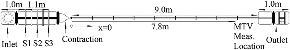
Figure 17: Schematic of the experimental facility
Olson et al. utilized one-component Molecular Tagging Velocimetry (1C-MTV) to study laminar separation bubbles (LSBs) above the SD7003 airfoil at low Reynolds numbers. This study underscores the complexities involved in accurately characterizing LSBs over low Reynolds number airfoils, including measurement accuracy and sensitivity to various factors [134].
Bohl et al. investigated the noise generated during blade vortex interactions in a helicopter rotor, emphasizing the importance of understanding the dynamics of a concentrated vortex core for noise control and aerodynamic performance. The study employed Molecularly Labeled Velocimetry (MTV) to track the fluid velocity vector in the vortex core in detail, avoiding the complications of particle seeding. However, the study used stereo MTV applied to a limited number of z positions in the x-y plane, which may constrain the detailed analysis of vortex dynamics downstream of the vortex [135].
Fort et al. introduced a new technique called two-dimensional micro-Molecular Tagging Velocimetry (µMTV) to measure wall shear stress in high Reynolds number flows, overcoming the limitations of traditional methods such as Particle Image Velocimetry (PIV). This method uses Molecular Tagging Velocimetry (MTV) and a novel dye to achieve high-resolution flow characterization away from facility walls [136].
Andrade et al. discuss the use of Molecular Tagging Velocimetry (MTV) as a non-invasive technique for measuring high-velocity flow rates, particularly under supersonic conditions. Despite challenges such as reflections and weak signal-to-noise ratios, they found that MTV is a viable method for characterizing high-speed flow rates. They recommend future upgrades to the laser components to enhance the signal-to-noise ratio and maintain stable energy output, which will further improve the accuracy of MTV measurements [137]. The MTV experimental setup is shown in Fig. 18.
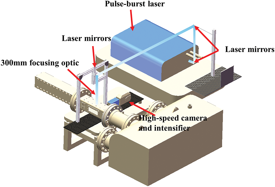
Figure 18: MTV experimental setup
Gevelber et al. utilized krypton tagged velocimetry (KTV) as the primary method for measuring flow velocities. The KTV-2D method was implemented in a Mach 3 wind tunnel, employing a mixture of krypton and nitrogen excited by a tunable laser beam to generate images for velocity analysis. This experimental setup includes advanced laser technology and a dedicated camera system designed to capture high-quality images, which are subsequently processed to extract velocity data. KTV, as a form of tagged velocity measurement, effectively avoids the issues associated with particle hysteresis in high-velocity flows [138]. Fig. 19 illustrates a schematic of the KTV-2D experimental setup.
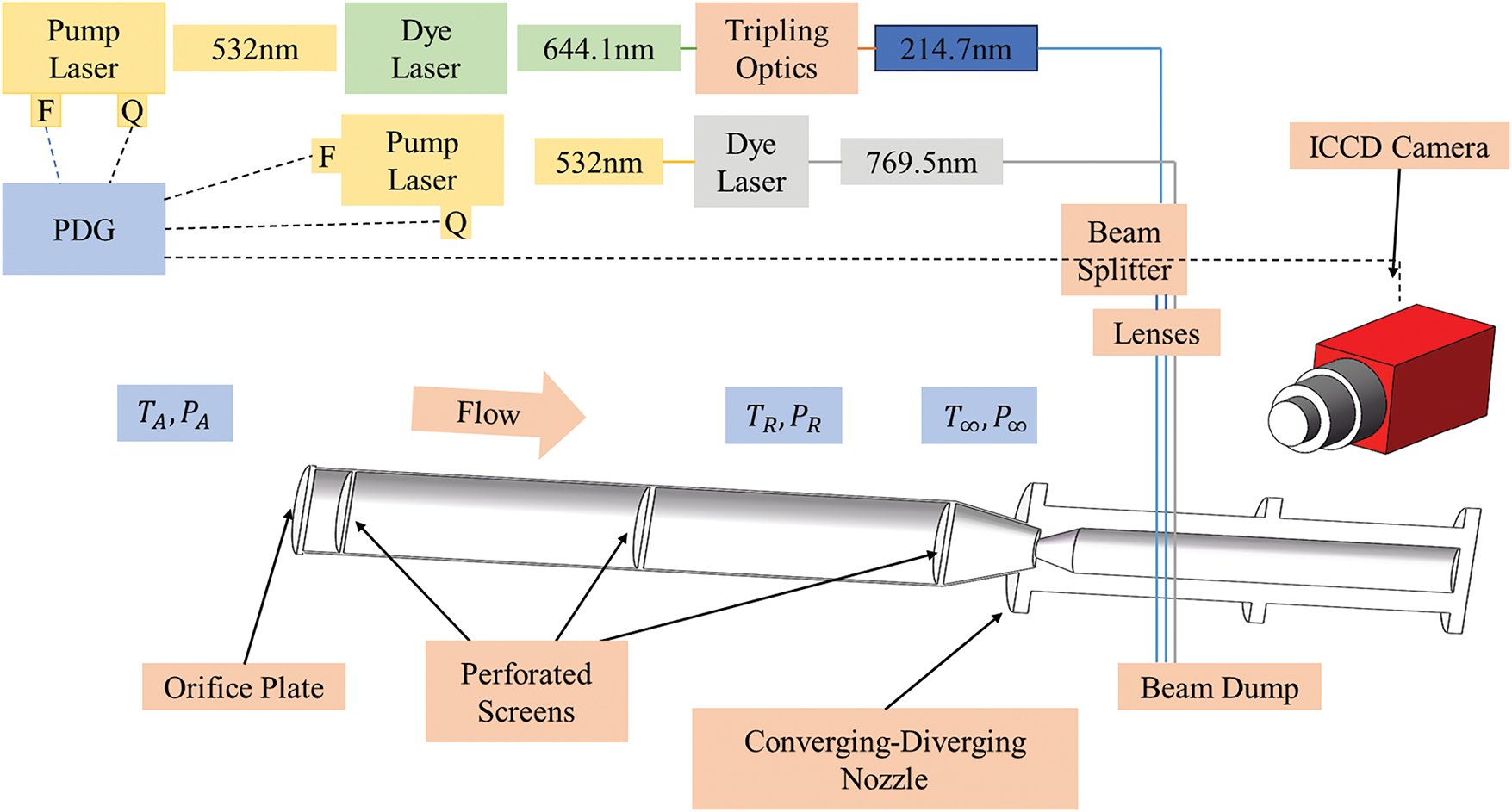
Figure 19: Schematic of KTV-2D experimental setup
Infrared thermography is a non-contact measurement technique that captures infrared radiation emitted by a target, using an infrared detector to produce corresponding infrared images. These images directly represent the temperature distribution across various locations on the target’s surface. An infrared thermography system typically comprises an infrared optical imaging system, an infrared detector, a cooler, an electronic information processing system, and a display system [139–142]. Fig. 20 illustrates an example of infrared thermography.
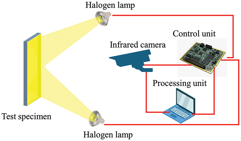
Figure 20: An example of the infrared thermography
Infrared thermography has been widely utilized in studying the dynamic stalling and transition of airfoils. During dynamic stall, the surface flow state of an airfoil undergoes complex changes, resulting in local temperature variations. Infrared thermography can monitor this temperature distribution changes on the surface of an airfoil in real-time, thereby revealing the flow characteristics during the stall process. Additionally, infrared thermography has been employed to measure the transition position of the airfoil surface in boundary layer studies. Given that heat exchange in the turbulent boundary layer is significantly higher than in laminar flow, the transition position is marked by a temperature jump. Infrared thermography can accurately capture this temperature change, determining the transition position and providing crucial data for airfoil design and performance optimization [143–145].
Gardner et al. introduced a novel method for detecting flow separation on helicopter main rotor blades using infrared thermography, generating stall maps without the complexity of pressure sensors. The experimental setup involved a sinusoidally tilted airfoil equipped with pressure sensors and a high-speed infrared camera to capture thermal images during airflow. Differential Infrared Thermography (DIT) methods were employed to analyze the intensity differences in the thermal images, allowing fluid separation to be identified by the calculated standard deviation. The study confirmed that the DIT method is effective under both static and dynamic conditions [146].
Wester et al. investigated the phenomenon of laminar-to-turbulent transition in fluid dynamics. The study, conducted in a wind tunnel, utilized Differential Image Thermal Imaging (DIT) to measure transitions at different inflow velocities and angles of attack. The research demonstrated that DIT is a powerful method for assessing the state of the boundary layer, enabling high-resolution measurements that closely align with the predictions of infiltration theory [147]. Fig. 21 illustrates the experimental setup.
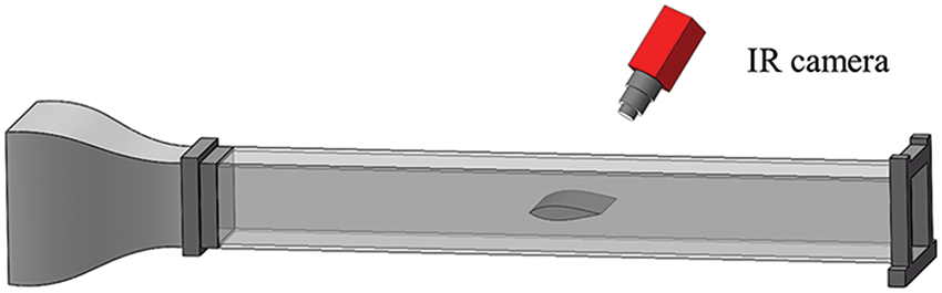
Figure 21: Experimental setup consisting of a G¨ottingen type wind tunnel, thermography camera shown in red, and a airfoil mounted on a rotary table
Wolf et al. employed differential infrared thermography (DIT) to measure the unsteady motion of laminar-to-turbulent transitions in the boundary layer. DIT enhances the detection of transitions in both static and dynamic cases, providing a reliable alternative to established methods and revealing the complexity of temperature distribution during pitch oscillations. However, the signal strength of DIT is significantly lower in dynamic scenarios compared to static ones. This reduced signal strength hinders the accurate detection of transition points in dynamic conditions [148].
Christian Wolf et al. introduced infrared thermography (IRT) and differential infrared thermography (DIT) to study the laminar-turbulent transition in the boundary layer (BL) using temperature-sensitive paint (TSP). Their research demonstrated that IRT and DIT techniques can effectively measure BL transitions. However, the effectiveness of IRT in detecting the transition location is influenced by factors such as surface coating and camera technology, which can limit the accuracy and reliability of the measurements [149].
Gardner et al. investigated and analyzed differential infrared thermography (DIT), discovering that it effectively measures unsteady motion at boundary layer transition locations on unprepared surfaces without the need for contact. DIT offers a non-contact alternative to traditional methods such as thermal film anemometry, which require extensive sensor arrays and complex data analysis, making it particularly suitable for unsteady flow measurements [150]. Fig. 22 illustrates a sketch of the DIT experimental setup.
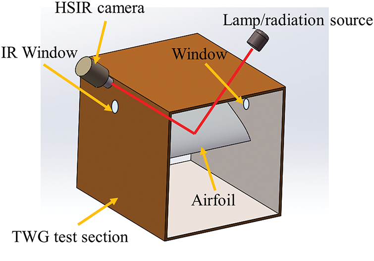
Figure 22: Sketch of the DIT experimental setup
The Laser Doppler Velocimeter (LDV) is an instrument that utilizes the laser Doppler effect for high-precision velocity measurements. By measuring the Doppler shift of reflected or scattered laser light, it can determine the speed of a moving object. The LDV offers several advantages, including non-contact measurement, fast dynamic response, a wide measurement range, and high resolution [151–154]. Fig. 23 shows an example of an LDV.
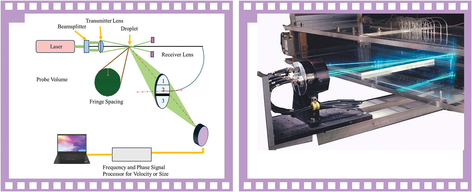
Figure 23: An example of an LDV
In the study of dynamic stall and transition of airfoils, the LDV plays a crucial role. It accurately measures the velocity distribution on the airfoil surface and in the surrounding flow field, capturing real-time velocity changes. This capability aids researchers in analyzing the mechanisms of stalling and transition, understanding their development processes, and assessing their impact on the aerodynamic performance of the airfoil [155–157].
Simanto et al. conducted experimental studies on tip vortex cavity deformation and fluid dynamics using high-speed imaging and laser Doppler velocimetry (LDV) measurements. The LDV enabled precise measurements of the velocity distribution, as well as the size and strength of the vortices, under both cavitation and non-cavitation conditions [158].
Le Page et al. present a study on hypersonic front separation using laser-induced fluorescence velocimetry. Their research reveals inhomogeneous velocity distributions and complex flow structures, offering valuable insights into hypersonic flow behavior and separation phenomena. The study highlights the effectiveness of advanced velocimetry techniques in understanding these intricate dynamics [159].
Barnhart designs and develops coherent detection Rayleigh Doppler lidar systems as an alternative velocity measurement technique for wind tunnels. This research highlights the potential of a Doppler wind measurement lidar system to provide accurate, non-invasive velocity measurements in wind tunnels. By addressing many limitations of current technology, this research paves the way for more advanced aerodynamic testing methods [160].
Pressure Sensitive Paint (PSP) technology is an innovative method that uses optical properties to measure the pressure and temperature distribution on an object’s surface. By coating the surface with a special pressure-sensitive paint, a light source such as a laser or UV light excites the paint to emit fluorescent or phosphorescent light. The pressure distribution on the surface is then calculated by analyzing the changes in the intensity of the emitted light. PSP technology offers several advantages, including contactless measurement, a wide detection range, low cost, short preparation time, and the ability to avoid interference with the flow field by traditional detection techniques [161–165].
PSP technology is particularly valuable in studying the dynamic stall and transition characteristics of airfoils. By utilizing PSP, researchers can accurately measure real-time changes in pressure distribution on the airfoil surface during dynamic stall and transition processes. This allows for the effective identification of high-pressure regions and their dynamic characteristics. When combined with flow visualization methods such as ripples and shadows, PSP enables a deeper understanding of the physical mechanisms behind these complex flow phenomena.
4 AI-Based Experimental Method
In the current frontiers of scientific research, AI methods are increasingly being utilized to address scientific and engineering challenges across various fields [166–170]. Similarly, the integration of AI techniques with experimental research methods for studying the transition and dynamic stalling of wing structures is exhibiting a trend toward greater diversification and refinement. These combined approaches not only enhance the accuracy but also improve the efficiency of experiments. For example, in recent years motion capture has become a powerful tool for experimentation in engineering with the help of artificial intelligence [171–173]. Artificial intelligence can significantly improve research efficiency and accuracy. Through machine learning, AI can quickly process and analyse large amounts of experimental data, identify transition points and dynamic stall regions, and reduce manual intervention. In addition, AI can simulate multi-scale, non-linear flow characteristics and help design optimal airfoils through optimisation algorithms to predict performance under different conditions. AI can also automate experimental design and real-time adjustments to improve experimental precision and efficiency.
Fig. 24 illustrates the main applications and promising AI methods in the experimental study of airfoil transition and dynamic stall. In the experimental research on dynamic stall and transition of airfoil structures, various algorithms offer unique advantages, providing multi-dimensional data processing and analysis methods.
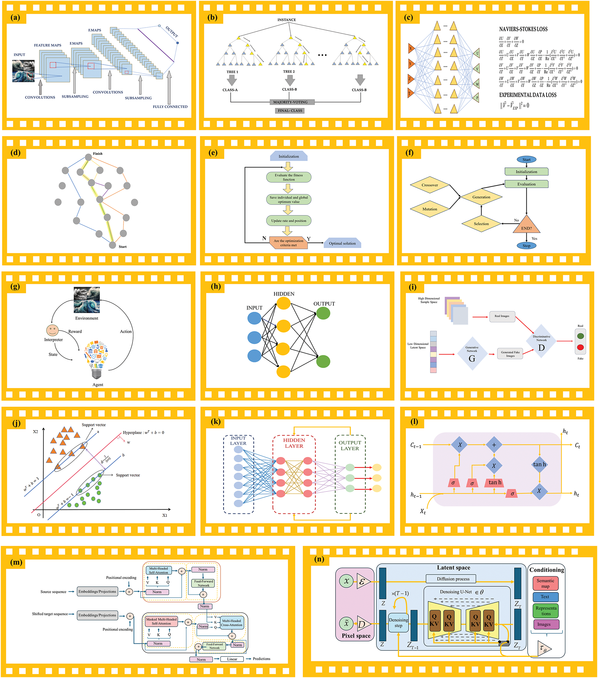
Figure 24: Main applications and potential artificial intelligence methods in experimental studies of airfoil transitions and dynamic stalls. (a) Convolutional neural network (CNN). (b) Random forest. (c) Physics-informed neural networks. (d) Ant colony optimization algorithm (ACO). (e) Particle swarm optimization (PSO). (f) Genetic algorithm. (g) Reinforcement learning (RL). (h) Artificial neural network (ANN). (i) Generative adversarial network (GAN). (j) Support vector machine (SVM). (k) Recurrent neural network (RNN). (l) Long short-term memory (LSTM). (m) Standard Transformer architecture with encoder on the top side and decoder on the bottom side. (n) Diffusion Models
4.1 Convolutional Neural Networks
Convolutional Neural Networks (CNNs) excel in analyzing high-resolution images and videos, enabling the extraction and quantitative analysis of key features from captured surface flow images of airfoils [174–176]. Lee et al. introduced PIV-DCNN, a sophisticated four-level regression deep convolutional neural network developed to enhance displacement extraction accuracy in particle image velocimetry (PIV). This innovative approach leverages network training and outlier replacement techniques, demonstrating superior performance compared to traditional PIV methods in both synthetic and experimental PIV image applications [177].
Memari et al. employed a convolutional neural network (CNN) to automatically extract spatial features from thermal images, enhancing the detection of defects in wind turbine blades. This approach significantly improves the accuracy and efficiency of the inspection process [178].
Cao et al. combined a convolutional neural network (CNN) with particle image velocimetry (PIV) to predict flow velocity fields, achieving enhanced spatial resolution and computational efficiency compared to traditional methods [179].
Zhu et al. introduced an innovative method that integrates a convolutional neural network (CNN) with particle image velocimetry (PIV) to enhance the volumetric reconstruction of flowing particles. This approach effectively overcomes the limitations of traditional tomographic reconstruction algorithms, which often result in coarse reconstructions and are prone to noise and ghost particles. By embedding the geometric information of the imaging system into the 3D CNN, this method significantly refines the reconstruction process, leading to improved accuracy, efficiency, and noise resistance [180].
Random Forests, through the ensemble of multiple decision trees, enhance prediction accuracy and robustness while identifying important feature variables from experimental data [181–183].
Hadipour-Gudarzi et al. employed a random forest algorithm to process data from wind tunnel tests, using fabric parameters such as angle of attack and wind speed as input. This approach enabled them to quickly and accurately estimate the lift and drag coefficients of the membrane airfoil [184].
Zhang et al. propose a hybrid method that combines Random Forest and Compressive Sensing (RF_CS) to accurately reconstruct transonic buffet aerodynamic noise from sparse data [185].
4.3 Physics-Informed Neural Networks
Physics-Informed Neural Networks (PINNs) combine the strengths of physical laws and neural networks, ensuring a natural integration of experimental data with physical models and maintaining physical consistency [186–188]. Cai et al. propose a method to enhance velocity measurements in particle image velocimetry (PIV) and particle tracking velocimetry (PTV) for turbulence analysis by utilizing a physically-informed neural network (PINN). This approach infers the pressure field even when direct pressure data is unavailable, effectively reducing measurement noise and improving the accuracy of fluid dynamics experiments [189].
Moreno Soto et al. employed a Physical Information Neural Network (PINN) to improve the reconstruction of the fluid flow field. By integrating the Navier-Stokes equations with data from particle image velocimetry and pressure sensors, their approach enhanced accuracy and allowed for the extraction of additional derived quantities, such as pressure distribution [190].
4.4 Other Algorithms with Potential
Ant Colony Optimization (ACO) and Particle Swarm Optimization (PSO) can be utilized for global optimization of experimental parameters, aiding in the identification of optimal experimental conditions and ensuring the reliability and reproducibility of results [191,192].
Genetic Algorithms (GAs), by simulating the process of natural evolution, optimize experimental design and result analysis, thereby improving the adaptability and innovativeness of experimental schemes [193,194].
Reinforcement Learning (RL) can be employed for real-time adjustment of dynamic experimental conditions, enhancing experimental efficiency and the precision of data acquisition [195,196].
Artificial Neural Networks (ANNs) exhibit unique advantages in handling complex nonlinear data, making them suitable for nonlinear modeling and prediction of experimental data, thereby enhancing the understanding of flow characteristics [197,198].
Generative Adversarial Networks (GANs) can generate simulated data similar to the experimental data distribution, enriching the experimental dataset and facilitating the study of rare or extreme conditions [199,200].
Support Vector Machines (SVMs) excel in classification and regression analysis, making them suitable for the classification and pattern recognition of experimental data, especially in small sample datasets [201,202].
Recurrent Neural Networks (RNNs) and Long Short-Term Memory Networks (LSTMs) are advantageous in processing time-series data, making them suitable for analyzing time-dependent data in experiments and capturing the dynamic processes of flow changes. The integrated application of these algorithms not only enhances the efficiency and accuracy of experimental research on dynamic stall and transition of airfoil structures but also promotes in-depth understanding and innovative exploration of complex flow phenomena in this field [203–206].
The Transformer model architecture has made significant advancements in machine learning and artificial intelligence in recent years. It holds great potential for experimental fluid dynamics studies, particularly in wing transition and dynamic stall, due to its powerful sequence modeling capabilities, self-attention mechanism, and flexibility in handling high-dimensional data. The self-attention mechanism allows the Transformer to capture complex dependencies between different regions in the flow field, making it especially well-suited for analyzing time-series data and experimental fluid data with disordered inputs. Furthermore, when combined with reinforcement learning, Transformer models can optimize fluid control strategies, enhancing the accuracy and efficiency of stall control. Its computational efficiency also reduces the resources required for traditional numerical simulations, significantly improving simulation performance [207–209].
The Diffusion Model, a probabilistic-based generative model widely used in image generation, natural language processing, and other fields, also demonstrates considerable potential in experimental fluid dynamics, particularly in airfoil transition and dynamic stall studies. With its unsupervised learning capability and stepwise denoising process, the Diffusion Model efficiently simulates complex fluid phenomena, captures the spatial and temporal variations in detail, and generates accurate models of high-dimensional fluid data. Its ability to generate realistic flow fields allows researchers to gain a more intuitive understanding of changes in aerodynamic behavior, especially during the non-stationary processes of dynamic stall and transition. Moreover, the Diffusion Model effectively handles noise and uncertainty in experimental data, optimizing the reconstruction of fluid scenes and thereby improving prediction accuracy [210,211].
5.1 Limitations and Challenges
Airfoil structures have evolved from their early aerospace applications to become integral components across a wide range of fields, including civil engineering, chemical engineering, biomedical engineering, ocean engineering, energy and power engineering, and vehicle engineering. Despite the significant advancements in experimental research technologies, challenges persist, particularly in regard to the high costs of experiments. Dynamic stall and transition remain pressing issues in airfoil research. Although technological progress has accelerated the development of experimental methods, current research still faces various problems and challenges that need addressing.
(1) Airfoil structures are applied in multiple fields, each with different functional requirements for airfoils. Additionally, research on airfoil structures involves various disciplines. Currently, interdisciplinary communication and collaboration are insufficient, which limits the potential for innovative thinking and technological integration.
(2) Experimental equipment and test conditions often differ from the actual environment, making it difficult to fully reproduce the working conditions encountered in real operations. As a result, experimental results may deviate from real-world scenarios. For example, when studying the wing structure of wind power equipment, it is impossible to replicate the presence of dust and other environmental factors in the laboratory setting.
(3) The challenge of capturing subtle flow phenomena and structural responses with current experimental equipment limits our ability to fully understand these phenomena in depth.
(4) To study complex systems effectively, it is necessary to integrate various experimental tools and techniques. However, existing equipment often focuses on specific aspects in isolation, making it challenging to comprehensively understand the overall behavior of complex systems.
(5) Despite advancements in experimental technology, high-precision equipment remains costly, which limits its use in a broad range of research applications. This is especially true for equipment capable of accurately simulating complex flow phenomena.
(6) The massive amount of experimental data has made it a significant challenge to process and analyze this information efficiently and accurately. Traditional data processing methods may no longer meet the demands of current research.
(7) Experimental conditions often have limited controllability. For instance, wind tunnel experiments typically employ scaled-down models, but parameters such as Reynolds number and Mach number may differ from real-world conditions due to the scaling. This discrepancy can impact the accuracy of the experimental results.
5.2 Suggestions and Prospectives
In response to these challenges and constraints, several development proposals have emerged based on the review.
(1) To establish interdisciplinary research teams and cooperation platforms, foster exchanges and collaboration across diverse disciplines, and integrate the strengths of various fields in order to holistically address complex problems.
(2) Development of new materials for the manufacture of experimental equipment, aimed at achieving cost-effectiveness, efficiency, and enhanced accuracy in experiments.
(3) Actively combining traditional experimental methods with artificial intelligence techniques, leveraging the advantages of AI to achieve efficient and accurate experiments.
(4) Researching higher precision sensors and detection technologies to enhance the equipment’s ability to capture subtle phenomena, such as through the research and application of nanotechnology, micro-electro-mechanical systems (MEMS), and other cutting-edge technologies aimed at improving the detection accuracy and sensitivity of experimental equipment.
(5) Design and development of equipment that integrates multiple experimental functions, enabling simultaneous multi-faceted research within a single system, thereby enhancing research efficiency and comprehensiveness. For instance, the development of a comprehensive experimental platform that incorporates wind tunnels, flow visualization, vibration analysis, and other functionalities to facilitate comprehensive research on complex systems.
(6) Develop advanced data processing and analysis techniques, such as machine learning-based data assimilation, to address the challenges posed by large volumes of experimental data.
(7) By designing more sophisticated control systems to simulate dynamic stall and transition scenarios that more closely resemble real flight conditions, precise unsteady control can be achieved, including adjustable vibrations, disturbances, and aeroelastic effects.
(8) By integrating various measurement techniques (such as PIV, pressure sensors, infrared thermography, etc.), synchronized high-precision measurements of multiple physical quantities, including flow fields, pressure distribution, and temperature fields, can be achieved to comprehensively describe transition and dynamic stall phenomena.
Acknowledgement: The authors would like to express their sincere gratitude to all those who have offered their help and support.
Funding Statement: This research was funded by Program for Scientific Research Start-up Funds of Guangdong Ocean University, grant number 060302072101, Zhanjiang Marine Youth Talent Project Comparative Study and Optimization of Horizontal Lifting of Subsea Pipeline, grant number 2021E5011.
Author Contributions: For research articles with several authors, a short paragraph specifying their individual contributions must be provided. The following statements should be used. Conceptualization, Yifan Xie and Dapeng Zhang; methodology, Dapeng Zhang; software, Yifan Xie and Dapeng Zhang; validation, Yining Zhang, Zhengjie Liang and Dapeng Zhang; formal analysis, Yutao Tian; investigation, Yifan Xie; resources, Dapeng Zhang; data curation, Yining Zhang; writing—original draft preparation, Yifan Xie; writing—review and editing, Dapeng Zhang and Zhengjie Liang; visualization, Yining Zhang and Yutao Tian; supervision, Dapeng Zhang; project administration, Dapeng Zhang. All authors reviewed the results and approved the final version of the manuscript.
Availability of Data and Materials: Data sharing not applicable to this article as no datasets were generated or analyzed during the current study.
Ethics Approval: There were no ethical issues involved in this study.
Conflicts of Interest: The authors declare no conflicts of interest to report regarding the present study.
References
1. Zhang D, Zhang Y, Zhao B, Ma Y, Si K. Exploring subsea dynamics: a comprehensive review of underwater pipelines and cables. Phys Fluids. 2024;36(10):101304. doi:10.1063/5.0231898. [Google Scholar] [CrossRef]
2. Zhang D. Engineering solutions to mechanics, marine structures and infrastructures. Eng Solut Mech Mar Struct Infrastruct. 2024;1(1). doi:10.58531/esmmsi/1/1/1. [Google Scholar] [CrossRef]
3. Eppler R. Airfoil design and data. Heidelberg, German: Springer Science & Business Media; 2012. [Google Scholar]
4. Abbott IH, Von Doenhoff AE, Stivers L Jr. Summary of airfoil data. No. NACA-TR-824. 1945 [cited 2025 Jan 10]. Available from: https://ntrs.nasa.gov/citations/19930090976. [Google Scholar]
5. Kang D, Lee S. Aerodynamic and aeroacoustic effects of different transition mechanisms on an airfoil. AIAA J. 2024;62(4):1517–35. doi:10.2514/1.J063270. [Google Scholar] [CrossRef]
6. Fertis DG. New airfoil-design concept with improved aerodynamic characteristics. J Aerosp Eng. 1994;7(3):328–39. doi:10.1061/(ASCE)0893-1321(1994)7:3(328). [Google Scholar] [CrossRef]
7. Mani M, Dorgan AJ. A perspective on the state of aerospace computational fluid dynamics technology. Annu Rev Fluid Mech. 2023;55(1):431–57. doi:10.1146/annurev-fluid-120720-124800. [Google Scholar] [CrossRef]
8. Rozhdestvensky K, Zhao B. Recent advances in hydrodynamics of wing propulsive lifting systems for ships and underwater vehicles. Phys Fluids. 2023;35(11):111302. doi:10.1063/5.0169938. [Google Scholar] [CrossRef]
9. Sun Y, Zhang D, Wang Y, Zong Z, Wu Z. Model experimental study on a T-foil control method with anti-vertical motion optimization of the mono hull. J Mar Sci Eng. 2023;11(8):1551. doi:10.3390/jmse11081551. [Google Scholar] [CrossRef]
10. Gupta LK, Pandey M, Raj PA, Pu JH. Scour reduction around bridge pier using the airfoil-shaped collar. Hydrology. 2023;10(4):77. doi:10.3390/hydrology10040077. [Google Scholar] [CrossRef]
11. Ostenfeld KH, Larsen A. Bridge engineering and aerodynamics. In: Aerodynamics of large bridges. London, UK : Routledge; 2017. p. 3–22. [Google Scholar]
12. Sriram PS, Gopalarathnam A, Misenheimer A. High-downforce airfoil design for motorsports. SAE Int J Mater Manf. 2012;5(2):478–89. doi:10.4271/2012-01-1168. [Google Scholar] [CrossRef]
13. Zhou ZH. Design of F1 race car rear wing airfoil: optimizing the lift to drag ratio through numerical simulation. Front Soc Sci Technol. 2020;2(12):116–22. [Google Scholar]
14. Deng XW, Wu N, Yang K, Chan WL. Integrated design framework of next-generation 85-m wind turbine blade: Modelling, aeroelasticity and optimization. Compos Part B Eng. 2019;159(9):53–61. doi:10.1016/j.compositesb.2018.09.028. [Google Scholar] [CrossRef]
15. Sharma P, Gupta B, Pandey M, Sharma AK, Nareliya Mishra R. Recent advancements in optimization methods for wind turbine airfoil design: a review. Mater Today Proc. 2021;47(2–3):6556–63. doi:10.1016/j.matpr.2021.02.231. [Google Scholar] [CrossRef]
16. Sindera K, Korpyś M, Iwaniszyn M, Gancarczyk A, Suwak M, Kołodziej A. New streamlined catalytic carriers of enhanced transport properties: experiments vs CFD. Chem Eng J. 2022;450(6):138297. doi:10.1016/j.cej.2022.138297. [Google Scholar] [CrossRef]
17. Huque Z, Zemmouri G, Harby D, Kommalapati R. Optimization of wind turbine airfoil using nondominated sorting genetic algorithm and Pareto optimal front. Int J Chem Eng. 2012;2012:193021. doi:10.1155/2012/193021. [Google Scholar] [CrossRef]
18. Wu HC, Wang ZY, Lv XJ. Design and fluent simulation of impeller for axial maglev heart pump. Appl Mech Mater. 2012;195–196:29–34. doi:10.4028/www.scientific.net/AMM.195-196.29. [Google Scholar] [CrossRef]
19. Salleh NM, Mohamad SZ, Mohd Juzaila AL. Reducing of thrombosis in mechanical heart valve through the computational method: a review. J Adv Res Fluid Mech Ther Sci. 2020;65(2):178–200. [Google Scholar]
20. Zhang FN, Graham DJ. Air transport and economic growth: a review of the impact mechanism and causal relationships. Trans Rev. 2020;40(4):506–28. doi:10.1080/01441647.2020.1738587. [Google Scholar] [CrossRef]
21. Lenaerts B, Allroggen F, Malina R. The economic impact of aviation: a review on the role of market access. J Air Transp Manag. 2021;91(5):102000. doi:10.1016/j.jairtraman.2020.102000. [Google Scholar] [CrossRef]
22. Abrantes I, Ferreira AF, Magalhães LB, Costa M, Silva A. The impact of revolutionary aircraft designs on global aviation emissions. Renew Energy. 2024;223(9):119937. doi:10.1016/j.renene.2024.119937. [Google Scholar] [CrossRef]
23. Sobieralski JB. Sustainable air transportation through the operational use of a social cost index. J Clean Prod. 2023;385(6):135663. doi:10.1016/j.jclepro.2022.135663. [Google Scholar] [CrossRef]
24. Sears WR. Some recent developments in airfoil theory. J Aeronaut Sci. 1956;23(5):490–9. doi:10.2514/8.3588. [Google Scholar] [CrossRef]
25. Liu T. Evolutionary understanding of airfoil lift. Adv Aerodyn. 2021;3(1):37. doi:10.1186/s42774-021-00089-4. [Google Scholar] [CrossRef]
26. Liu Q, Xu Y, Li Y. Complex dynamics of a conceptual airfoil structure with consideration of extreme flight conditions. Nonlinear Dyn. 2023;111(16):14991–5010. doi:10.1007/s11071-023-08636-y. [Google Scholar] [CrossRef]
27. Traylor C, DiPaola M, Willis DJ, Inalpolat M. A computational investigation of airfoil aeroacoustics for structural health monitoring of wind turbine blades. Wind Energy. 2020;23(3):795–809. doi:10.1002/we.2459. [Google Scholar] [CrossRef]
28. Corke TC, Thomas FO. Dynamic stall in pitching airfoils: aerodynamic damping and compressibility effects. Annu Rev Fluid Mech. 2015;47(1):479–505. doi:10.1146/annurev-fluid-010814-013632. [Google Scholar] [CrossRef]
29. Visbal MR. Numerical investigation of deep dynamic stall of a plunging airfoil. AIAA J. 2011;49(10):2152–70. doi:10.2514/1.J050892. [Google Scholar] [CrossRef]
30. Liu B, Tang J, Huang H, Lu XY. Deep learning methods for super-resolution reconstruction of turbulent flows. Phys Fluids. 2020;32(2):025105. doi:10.1063/1.5140772. [Google Scholar] [CrossRef]
31. Brunton SL, Noack BR, Koumoutsakos P. Machine learning for fluid mechanics. Annu Rev Fluid Mech. 2020;52(1):477–508. doi:10.1146/annurev-fluid-010719-060214. [Google Scholar] [CrossRef]
32. Zhang Y, Zhang DP, Zhang YN, Xie YF, Xie BZ, Jiang HY. A comprehensive review of simulation software and experimental modeling on exploring marine collision analysis. Eng Trans. 2023;4(1):1–7. doi:10.61186/engt.4.1.2869. [Google Scholar] [CrossRef]
33. Zhang Y, Zhang DP, Jiang HY. Review of challenges and opportunities in turbulence modeling: a comparative analysis of data-driven machine learning approaches. J Mar Sci Eng. 2023;11(7):1440. doi:10.3390/jmse11071440. [Google Scholar] [CrossRef]
34. Zhang Y, Xie Y, Zhao G, Liang Z, Shi J, Yang Y. The important role of fluid mechanics in the engineering field. Eng Solut Mech Mar Struct Infrastruct. 2024;1(2) doi:10.58531/esmmsi/1/2/2. [Google Scholar] [CrossRef]
35. Oberkampf W, Trucano T. Validation methodology in computational fluid dynamics. In: Fluids 2000 Conference and Exhibit; 2000 Jun 19–22; Denver, CO. Reston, Virginia: AIAA; 2000. 2549 p. doi:10.2514/6.2000-2549. [Google Scholar] [CrossRef]
36. Lakshmikantham V, Sen SK. Computational error and complexity in science and engineering: computational error and complexity. London, UK: Elsevier; 2005. [Google Scholar]
37. Bussoletti J. CFD calibration and validation-The challenges of correlating computational model results with test data. In: 25th Plasmadynamics and Lasers Conference; 1994 Jun 20–23; Colorado Springs, CO. Reston, Virginia: AIAA; 1994. 2542 p. doi:10.2514/6.1994-2542. [Google Scholar] [CrossRef]
38. Oberkampf WL, Smith BL. Assessment criteria for computational fluid dynamics model validation experiments. J Verif Valid Uncertain Quantif. 2017;2(3):31002. doi:10.1115/1.4037887. [Google Scholar] [CrossRef]
39. Spalart PR, Venkatakrishnan V. On the role and challenges of CFD in the aerospace industry. Aeron J. 2016;120(1223):209–32. doi:10.1017/aer.2015.10. [Google Scholar] [CrossRef]
40. Sørensen NN, Méndez B, Munoz A, Sieros G, Jost E, Lutz T, et al. CFD code comparison for 2D airfoil flows. J Phys Conf Ser. 2016;753:82019. doi:10.1088/1742-6596/753/8/082019. [Google Scholar] [CrossRef]
41. Schmid, Peter J, et al. Transition to turbulence. In: Stability and transition in shear flows. New York, NY, USA : Springer Science and Business Media. 2001. p. 401–75. [Google Scholar]
42. Wu X, Moin P, Wallace JM, Skarda J, Lozano-Durán A, Hickey JP. Transitional-turbulent spots and turbulent-turbulent spots in boundary layers. Proc Natl Acad Sci U S A. 2017;114(27):1. doi:10.1073/pnas.1704671114. [Google Scholar] [PubMed] [CrossRef]
43. Yaglom AM. Hydrodynamic instability and transition to turbulence. Vol. 100. Dordrecht, Netherlands: Springer Science & Business Media; 2012. [Google Scholar]
44. Wilcox DC. Turbulence-model transition predictions. AIAA J. 1975;13(2):241–3. doi:10.2514/3.49679. [Google Scholar] [CrossRef]
45. Michel R. Determination du point de transition et calcul de la trainee des profiles dailes en incompressible. Tech. Rep. 1/1578A. ONERA. 1951 [cited 2025 Jan 10]. Available from: https://www.onera.fr/en. [Google Scholar]
46. Chen LL, Guo Z, Deng XL, Hou ZX. Aerodynamic performance and transition prediction of low-speed fixed-wing unmanned aerial vehicles in full configuration based on improved γ-Reθ model. Aerosp Sci Technol. 2020;107(9):106281. doi:10.1016/j.ast.2020.106281. [Google Scholar] [CrossRef]
47. Menter FR, Langtry RB, Likki SR, Suzen YB, Huang PG, Völker S. A correlation-based transition model using local variables: part I: model formulation. J Turbomach. 2006;128(3):413. doi:10.1115/1.2184352. [Google Scholar] [CrossRef]
48. Zheng Z, Lei J. Application of the γ-Reθtranstion model to simulations of the flow past a circular cylinder. Flow Turbul Combust. 2016;97(2):401–26. doi:10.1007/s10494-016-9706-9. [Google Scholar] [CrossRef]
49. Nandi TN, Brasseur J, Vijayakumar G. Prediction and analysis of the nonsteady transitional boundary layer dynamics for flow over an oscillating wind turbine airfoil using the γ-Reθtransition model. In: 34th Wind Energy Symposium; 2016 Jan 4–8; San Diego, CA, USA. Reston, Virginia: AIAA; 2016. 520 p. doi:10.2514/6.2016-0520. [Google Scholar] [CrossRef]
50. Lin G, Kusterer K, Ayed AH, Bohn D, Sugimoto T. Conjugate heat transfer analysis of convection-cooled turbine vanes using γ-Reθtransition model. Int J Gas Turbine Propuls Power Syst. 2014;6(3):9–15. doi:10.38036/jgpp.6.3_9. [Google Scholar] [CrossRef]
51. Wang Y, Zhang Y, Li S, Meng D. Calibration of a γ-Reθ transition model and its validation in low-speed flows with high-order numerical method. Chin J Aeronaut. 2015;28(3):704–11. doi:10.1016/j.cja.2015.03.002. [Google Scholar] [CrossRef]
52. Bader P, Pieringer P, Sanz W. On the capabitity of the γ-Reθ transition model to predict relaminarization. In: Proceedings of 12th European Conference on Turbomachinery Fluid dynamics & Thermodynamics ETC12; 2017 Apr 3–7; Stockholm, Sweden. [Google Scholar]
53. Langtry RB, Menter FR. Correlation-based transition modeling for unstructured parallelized computational fluid dynamics codes. AIAA J. 2009;47(12):2894–906. doi:10.2514/1.42362. [Google Scholar] [CrossRef]
54. Khayatzadeh P, Nadarajah S. Laminar-turbulent flow simulation for wind turbine profiles using the γ-transition model. Wind Energy. 2014;17(6):901–18. doi:10.1002/we.1606. [Google Scholar] [CrossRef]
55. Rubino G, Visonneau M. Improved crossflow transition predictions for the one-equation γ transition model. Comput Fluids. 2022;245(4):105580. doi:10.1016/j.compfluid.2022.105580. [Google Scholar] [CrossRef]
56. Liu Y, Luo P, Tang Y. Improved prediction of turbomachinery flows using Reynolds stress model with γ transition model. Aerosp Sci Technol. 2024;144(1):108812. doi:10.1016/j.ast.2023.108812. [Google Scholar] [CrossRef]
57. Mulleners K, Raffel M. Dynamic stall development. Exp Fluids. 2013;54(2):1469. doi:10.1007/s00348-013-1469-7. [Google Scholar] [CrossRef]
58. Johnson W, Ham ND. On the mechanism of dynamic stall. J Am Helicopter Soc. 1972;17(4):36–45. doi:10.4050/JAHS.17.36. [Google Scholar] [CrossRef]
59. McCroskey WJ. The phenomenon of dynamic tall. No. A-8464. NASA Technical Reports Server. 1981 [cited 2025 Jan 10]. Available from: https://ntrs.nasa.gov/citations/19810011501. [Google Scholar]
60. Gardner AD, Jones AR, Mulleners K, Naughton JW, Smith MJ. Review of rotating wing dynamic stall: Experiments and flow control. Prog Aerosp Sci. 2023;137(1):100887. doi:10.1016/j.paerosci.2023.100887. [Google Scholar] [CrossRef]
61. Galvanetto U, Peiró J, Chantharasenawong C. An assessment of some effects of the nonsmoothness of the Leishman-Beddoes dynamic stall model on the nonlinear dynamics of a typical aerofoil section. J Fluids Struct. 2008;24(1):151–63. doi:10.1016/j.jfluidstructs.2007.07.008. [Google Scholar] [CrossRef]
62. Melani PF, Aryan N, Greco L, Bianchini A. The Beddoes-Leishman dynamic stall model: critical aspects in implementation and calibration. Renew Sustain Energy Rev. 2024;202:114677. doi:10.1016/j.rser.2024.114677. [Google Scholar] [CrossRef]
63. Pereira R, Schepers G, Pavel MD. Validation of the Beddoes-Leishman dynamic stall model for horizontal axis wind turbines using MEXICO data. Wind Energy. 2013;16(2):207–19. doi:10.1002/we.541. [Google Scholar] [CrossRef]
64. Liu X, Liang S, Li G, Godbole A, Lu C. An improved dynamic stall model and its effect on wind turbine fatigue load prediction. Renew Energy. 2020;156(Part 2):117–30. doi:10.1016/j.renene.2020.04.040. [Google Scholar] [CrossRef]
65. Joseph J, Sathyabhama A. Leading edge tubercle on wind turbine blade to mitigate problems of stall, hysteresis, and laminar separation bubble. Energy Convers Manag. 2022;255(3):115337. doi:10.1016/j.enconman.2022.115337. [Google Scholar] [CrossRef]
66. Modarres R. Semi-empirical modeling of two-dimensional and three-dimensional dynamic stall. 2021. [cited 2025 Jan 10]. Available from: https://openscholarship.wustl.edu/eng_etds/161/. [Google Scholar]
67. Tran CT, Falchero D. Application of the ONERA dynamic stall model to a helicopter blade in. 1981. [cited 2025 Jan 10]. Available from: https://ntrs.nasa.gov/api/citations/19850004554/downloads/19850004554.pdf. [Google Scholar]
68. McAlister KW, Lambert O, Petot D. Application of the ONERA model of dynamic stall. No. AVSCOM-TR-84-A-3. NASA Technical Reports Server. 1984. [cited 2025 Jan 10]. Available from: https://ntrs.nasa.gov/citations/19850004554. Document ID:19850004554. [Google Scholar]
69. Peters DA. Toward a unified lift model for use in rotor blade stability analyses. J Am Helicopter Soc. 1985;30(3):32–42. doi:10.4050/JAHS.30.3.32. [Google Scholar] [CrossRef]
70. Petot D. Progress in the semi-empirical prediction of the aerodynamic forces due to large amplitude oscillations of an airfoil in attached or separated flow. In: Ninth European Rotorcraft Forum; 1983 Sep 13–15; Stresa, Italy: Associazione Italiana di Aeronautica ed Astronautica Associazione Industrie Aerospaziali; 1983. [Google Scholar]
71. Kussner HG. General airfoil theory. 2018. [cited 2025 Jan 10]. Available from: https://ntrs.nasa.gov/citations/19930094437. [Google Scholar]
72. Drela M. Pros & cons of airfoil optimization. Front Comput Fluid Dyn. 1998;1:363–81. doi:10.1142/3975. [Google Scholar] [CrossRef]
73. Henne PA, Gregg RDIII. New airfoil design concept. J Aircr. 1991;28(5):300–11. doi:10.2514/3.46028. [Google Scholar] [CrossRef]
74. Ahmed MR, Sharma SD. An investigation on the aerodynamics of a symmetrical airfoil in ground effect. Exp Therm Fluid Sci. 2005;29(6):633–47. doi:10.1016/j.expthermflusci.2004.09.001. [Google Scholar] [CrossRef]
75. Chakroun W, Al-Mesri I, Al-Fahad S. Effect of surface roughness on the aerodynamic characteristics of a symmetrical airfoil. Wind Eng. 2004;28(5):547–64. doi:10.1260/0309524043028136. [Google Scholar] [CrossRef]
76. Ahmed MR. Aerodynamics of a cambered airfoil in ground effect. Inter J Fluid Mech Res. 2005;32(2):157–83. doi:10.1615/InterJFluidMechRes.v32.i2.30. [Google Scholar] [CrossRef]
77. Ranzenbach R, Barlow J. Cambered airfoil in ground effect-an experimental and computational study. In: SAE Technical Paper Series. Warrendale, PA, USA: SAE International; 1996. doi:10.4271/960909. [Google Scholar] [CrossRef]
78. Wang Z, Gursul I. Lift enhancement of a flat-plate airfoil by steady suction. AIAA J. 2017;55(4):1355–72. doi:10.2514/1.J055382. [Google Scholar] [CrossRef]
79. Cleaver DJ, Wang Z, Gursul I. Investigation of high-lift mechanisms for a flat-plate airfoil undergoing small-amplitude plunging oscillations. AIAA J. 2013;51(4):968–80. doi:10.2514/1.J052213. [Google Scholar] [CrossRef]
80. Abdul Hamid M, Toufique Hasan ABM, Alimuzzaman SM, Matsuo S, Setoguchi T. Compressible flow characteristics around a biconvex arc airfoil in a channel. Propuls Power Res. 2014;3(1):29–40. doi:10.1016/j.jppr.2014.01.002. [Google Scholar] [CrossRef]
81. Haas AP, Hader C, Fasel HF. Linear stability investigation of cross-flow instability for a supersonic swept wing with a biconvex airfoil. In: AIAA Aviation 2021 Forum; 2021 Aug 2–6; Reston, Virginia: AIAA; 2021. 2848 p. doi:10.2514/6.2021-2848. [Google Scholar] [CrossRef]
82. Takeyeldein MM, Lazim TM, Mohd N, Ishak IS, Ali EA. Wind turbine design using thin airfoil SD2030. In: Evergreen. Kyushu, Japan: Kyushu University Institutional Repository; 2010. [Google Scholar]
83. Amiet RK. High frequency thin-airfoil theory for subsonic flow. AIAA J. 1976;14(8):1076–82. doi:10.2514/3.7187. [Google Scholar] [CrossRef]
84. Yang J, Meng L, Wang X, Yang H. Research on data assimilation approach of wind turbine airfoils in stall conditions. Renew Energy. 2025;239(7):122071. doi:10.1016/j.renene.2024.122071. [Google Scholar] [CrossRef]
85. Jia X, Zhang J, Chen D, Tang Z, Huang Q, Zhou C, et al. Impact of key airfoil blade parameters on the internal flow and vibration characteristics of centrifugal pumps. Phys Fluids. 2025;37(1):15134. doi:10.1063/5.0245675. [Google Scholar] [CrossRef]
86. Rogowski K, Mikkelsen RF, Michna J, Wiśniewski J. Aerodynamic performance analysis of NACA, 0018 airfoil at low Reynolds numbers in a low-turbulence wind tunnel. Adv Sci Technol Res J. 2025;19(2):136–50. doi:10.12913/22998624/195556. [Google Scholar] [CrossRef]
87. Li Z, Lyu W, Gong C, Zhou S, Cheng L. Experimental investigation and dynamic analysis of a novel electromagnetic energy harvester based on airfoil flutter. Energy Convers Manag. 2025;326:119471. doi:10.1016/j.enconman.2024.119471. [Google Scholar] [CrossRef]
88. Ünal N, Öz Y, Ünal EA, Oktay T. Enhancing aerodynamic performance of a two-dimensional airfoil using plasma actuators. Aerosp Sci Technol. 2025;158(1):109882. doi:10.1016/j.ast.2024.109882. [Google Scholar] [CrossRef]
89. Jardin T, Ferrand V, Gowree ER. NACA0012 airfoil at Reynolds numbers between 50,000 and 140,000: part 1: steady freestream. Int J Heat Fluid Flow. 2025;112(8):109655. doi:10.1016/j.ijheatfluidflow.2024.109655. [Google Scholar] [CrossRef]
90. Aboelezz A, Beltran M, Hargather MJ, Hassanalian M, Roghanchi P. Comprehensive design and performance validation of a wind tunnel for advanced respirable dust deposition investigations. J Hazard Mater. 2024;478:135516. doi:10.1016/j.jhazmat.2024.135516. [Google Scholar] [PubMed] [CrossRef]
91. Jia Y, Huang J, Liu Q, Zhao Z, Dong M. The wind tunnel test research on the aerodynamic stability of wind turbine airfoils. Energy. 2024;294(2):130889. doi:10.1016/j.energy.2024.130889. [Google Scholar] [CrossRef]
92. Keisar D, Arava I, Greenblatt D. Dynamic-stall-driven vertical axis wind turbine: an experimental parametric study. Appl Energy. 2024;365:123199. doi:10.1016/j.apenergy.2024.123199. [Google Scholar] [CrossRef]
93. Raus D, Cotté B, Monchaux R, Jondeau E, Souchotte P, Roger M. Experimental study of the dynamic stall noise on an oscillating airfoil. J Sound Vib. 2022;537(1):117144. doi:10.1016/j.jsv.2022.117144. [Google Scholar] [CrossRef]
94. Li G, Zhang W, Jiang Y, Yang P. Experimental investigation of dynamic stall flow control for wind turbine airfoils using a plasma actuator. Energy. 2019;185(4):90–101. doi:10.1016/j.energy.2019.07.017. [Google Scholar] [CrossRef]
95. Mayer YD, Zang B, Azarpeyvand M. Aeroacoustic investigation of an oscillating airfoil in the pre-and post-stall regime. Aerosp Sci Technol. 2020;103:105880. doi:10.1016/j.ast.2020.105880. [Google Scholar] [CrossRef]
96. Zhang YN, Zhang MM, Cai C, Xu JZ. Aerodynamic load control on a dynamically pitching wind turbine airfoil using leading-edge protuberance method. Acta Mech Sin. 2020;36(2):275–89. doi:10.1007/s10409-020-00939-2. [Google Scholar] [CrossRef]
97. Li S, Li Y, Yang C, Zheng X, Wang Q, Wang Y, et al. Experimental and numerical investigation of the influence of roughness and turbulence on LUT airfoil performance. Acta Mech Sin. 2019;35(6):1178–90. doi:10.1007/s10409-019-00898-3. [Google Scholar] [CrossRef]
98. Amandolese X, Széchényi E. Experimental study of the effect of turbulence on a section model blade oscillating in stall. Wind Energy. 2004;7(4):267–82. doi:10.1002/we.137. [Google Scholar] [CrossRef]
99. Wang Q, Zhao Q. Experiments on unsteady Vortex flowfield of typical rotor airfoils under dynamic stall conditions. Chin J Aeronaut. 2016;29(2):358–74. doi:10.1016/j.cja.2016.02.013. [Google Scholar] [CrossRef]
100. Aboelezz A, Ghali H, Elbayomi G, Madboli M. A novel VAWT passive flow control numerical and experimental investigations: guided vane airfoil wind turbine. Ocean Eng. 2022;257(1):111704. doi:10.1016/j.oceaneng.2022.111704. [Google Scholar] [CrossRef]
101. Phillips E, Wygnanski I. Use of sweeping jets during transient deployment of a control surface. AIAA J. 2013;51(4):819–28. doi:10.2514/1.J051683. [Google Scholar] [CrossRef]
102. Ikami T, Fujita K, Nagai H, Yorita D. Measurement of boundary layer transition on oscillating airfoil using cntTSP in low-speed wind tunnel. Meas Sci Technol. 2021;32(7):075301. doi:10.1088/1361-6501/abe2be. [Google Scholar] [CrossRef]
103. Quinn DB, Watts A, Nagle T, Lentink D. A new low-turbulence wind tunnel for animal and small vehicle flight experiments. R Soc Open Sci. 2017;4(3):160960. doi:10.1098/rsos.160960. [Google Scholar] [PubMed] [CrossRef]
104. Grogger HA, Gossar M, Makovec M, Fritz J, Neugebauer K, Amann F, et al. A low-cost wind tunnel for bird flight experiments. J Ornithol. 2022;163(2):599–610. doi:10.1007/s10336-021-01945-2. [Google Scholar] [PubMed] [CrossRef]
105. Brunner CE, Kiefer J, Hansen MOL, Hultmark M. Study of Reynolds number effects on the aerodynamics of a moderately thick airfoil using a high-pressure wind tunnel. Exp Fluids. 2021;62(8):178. doi:10.1007/s00348-021-03267-8. [Google Scholar] [CrossRef]
106. Li S. Model and flow control mechanism study of dynamic stall of wind turbine airfoil [Ph.D. dissertation]. China: University of Chinese Academy of Sciences (Institute of Engineering Thermophysics, Chinese Academy of Sciences); 2021. (In Chinese). [Google Scholar]
107. Chen L, Ye Q. PIV-based fast pressure reconstruction and noise prediction of tandem cylinder configuration. Exp Fluids. 2024;65(6):98. doi:10.1007/s00348-024-03833-w. [Google Scholar] [CrossRef]
108. Chen X, Zhong S, Ozer O, Kennaugh A, Liu T, Gao G. A study of spatiotemporal features of sweeping jets acting on afterbody vortices using low-operation-rate stereo PIV. Exp Therm Fluid Sci. 2024;158(6–7):111244. doi:10.1016/j.expthermflusci.2024.111244. [Google Scholar] [CrossRef]
109. Nguyen HS, Hieu TT, Thang NM, Tan HN, Can NT, Thao PT, et al. Selection of crankshaft manufacturing material by the PIV method. Eng Technol Appl Sci Res. 2024;14(4):14848–53. doi:10.48084/etasr.7514. [Google Scholar] [CrossRef]
110. Wong EKL, Sze EHY, Chung PWK, Wong LNY. Energy transfer and stress wave propagation during SPT through energy measurement and PIV. Proc Inst Civ Eng Geotech Eng. 2024;2024(1):1–13. doi:10.1680/jgeen.23.00320. [Google Scholar] [CrossRef]
111. Simão Ferreira C, van Kuik G, van Bussel G, Scarano F. Visualization by PIV of dynamic stall on a vertical axis wind turbine. Exp Fluids. 2009;46(1):97–108. doi:10.1007/s00348-008-0543-z. [Google Scholar] [CrossRef]
112. Wang Q, Zhao QJ, Zhao GQ. PIV experiments on flowfield characteristics of rotor airfoil dynamic stall and modifications of LB model. Chin J Theor Appl Mech. 2014;46(4):631–5. [Google Scholar]
113. van Doorne CWH, Westerweel J. Measurement of laminar, transitional and turbulent pipe flow using Stereoscopic-PIV. Exp Fluids. 2007;42(2):259–79. doi:10.1007/s00348-006-0235-5. [Google Scholar] [CrossRef]
114. Zhao Y, Lei C, Patterson JC. PIV measurements of the K-type transition in natural convection boundary layers. Exp Therm Fluid Sci. 2019;101(1):62–75. doi:10.1016/j.expthermflusci.2018.09.007. [Google Scholar] [CrossRef]
115. Adatrao S, van der Velden S, van der Meulen MJ, Bordes MC, Sciacchitano A. Design of experiments: a statistical tool for PIV uncertainty quantification. Meas Sci Technol. 2022;34(1):15201. doi:10.1088/1361-6501/ac9541. [Google Scholar] [CrossRef]
116. Saaid H, Voorneveld J, Schinkel C, Westenberg J, Gijsen F, Segers P, et al. Tomographic PIV in a model of the left ventricle: 3D flow past biological and mechanical heart valves. J Biomech. 2019;90:40–9. doi:10.1016/j.jbiomech.2019.04.024. [Google Scholar] [PubMed] [CrossRef]
117. Balducci A, Grigioni M, Querzoli G, Romano GP, Daniele C, D’Avenio G, et al. Investigation of the flow field downstream of an artificial heart valve by means of PIV and PTV. Exp Fluids. 2004;36(1):204–13. doi:10.1007/s00348-003-0744-4. [Google Scholar] [CrossRef]
118. Soodt T, Schröder F, Klaas M, van Overbrüggen T, Schröder W. Experimental investigation of the transitional bronchial velocity distribution using stereo scanning PIV. Exp Fluids. 2012;52(3):709–18. doi:10.1007/s00348-011-1103-5. [Google Scholar] [CrossRef]
119. Van Hooff T, Blocken B, Defraeye T, Carmeliet J, Van Heijst GJF. PIV measurements and analysis of transitional flow in a reduced-scale model: ventilation by a free plane jet with Coanda effect. Build Environ. 2012;56(6):301–13. doi:10.1016/j.buildenv.2012.03.020. [Google Scholar] [CrossRef]
120. Lang M, Rist U, Wagner S. Investigations on controlled transition development in a laminar separation bubble by means of LDA and PIV. Exp Fluids. 2004;36(1):43–52. doi:10.1007/s00348-003-0625-x. [Google Scholar] [CrossRef]
121. Zhang M, Chen J, Xu Z, Ruan X, Huang B. PIV measurement of cavitating flow around a pitching hydrofoil. J Phys: Conf Ser. 2024;2707(1):12137. doi:10.1088/1742-6596/2707/1/012137. [Google Scholar] [CrossRef]
122. Chen X, Feng Z, Ye Q. Amplitude modulation in turbulent boundary layer over anisotropic porous wall. Phys Fluids. 2024;36(2):025127. doi:10.1063/5.0187744. [Google Scholar] [CrossRef]
123. Nordstrom A, Leonov BS, Dogariu A. Femtosecond laser electronic excitation and tagging (FLEET) velocimetry at 60 kHz in hypersonic flows. In: AIAA Aviation Forum and Ascend; 2024 Jul 29–Aug 2; Las Vegas, Nevada. Reston, Virginia: AIAA; 2024.4586 p. doi:10.2514/6.2024-4586. [Google Scholar] [CrossRef]
124. Tareq MM, Fort C, Capanna R, Yamakaitis MJ, Azmy R, McDaniel K et al. Near-wall hydroxyl tagging velocimetry around a high-Reynolds number airfoil. In: AIAA SciTech 2024 Forum; 2024 Jan 8–12; Orlando, FL. Reston, Virginia: AIAA; 2024. 2327 p. doi:10.2514/6.2024-2327. [Google Scholar] [CrossRef]
125. Li F, Zhang H, Bai B. A review of molecular tagging measurement technique. Measurement. 2021;171:108790. doi:10.1016/j.measurement.2020.108790. [Google Scholar] [CrossRef]
126. Andrade A, Strasser NS, Posladek K, Combs CS, Glasby RS. Hypersonic wake velocity measurements using acetone molecular tagging velocimetry. In: AIAA Aviation Forum and Ascend; 2024 Jul 29–Aug 2; Las Vegas, Nevada. Reston, Virginia: AIAA; 2024. 4587 p. doi:10.2514/6.2024-4587. [Google Scholar] [CrossRef]
127. Rodrigues NS, Jiang N, Hsu P, Roy S, Danehy PM. Multiline molecular tagging velocimetry of nitric oxide at 100 kHz using an injection-seeded burst-mode OPO. Appl Opt. 2024;63(5):1247–57. doi:10.1364/AO.507732. [Google Scholar] [PubMed] [CrossRef]
128. Jiang N, Hsu PS, Roy S, Wang J, Hu H, Rodrigues N, et al. Long-lived nitric oxide molecular tagging velocimetry with 1 + 1 REMPI. Opt Lett. 2024;49(5):1297. doi:10.1364/OL.514912. [Google Scholar] [PubMed] [CrossRef]
129. Ramesh B, Klewicki JC, Philip J. Adopting molecular tagging velocimetry for high-resolution measurements of oscillating grid turbulence. Exp Fluids. 2024;65(4):46. doi:10.1007/s00348-024-03787-z. [Google Scholar] [CrossRef]
130. Hrynuk JT, Bohl DG. The effects of leading-edge tubercles on dynamic stall. J Fluid Mech. 2020;893:A5. doi:10.1017/jfm.2020.216. [Google Scholar] [CrossRef]
131. Albrecht MB, Naguib AM, Koochesfahani M. Single-component molecular tagging velocimetry of the boundary layer on a NACA-0012 airfoil plunging across uniform-shear flow. In: AIAA Scitech 2020 Forum; 2020 Jan 6–10; Orlando, FL. Reston, Virginia: AIAA; 2020. 2042 p. doi:10.2514/6.2020-2042. [Google Scholar] [CrossRef]
132. Bohl DG, Koochesfahani MM. MTV measurements of the vortical field in the wake of an airfoil oscillating at high reduced frequency. J Fluid Mech. 2009;620:63–88. doi:10.1017/S0022112008004734. [Google Scholar] [CrossRef]
133. Elsnab JR, Monty JP, White CM, Koochesfahani MM, Klewicki JC. Efficacy of single-component MTV to measure turbulent wall-flow velocity derivative profiles at high resolution. Exp Fluids. 2017;58(9):128. doi:10.1007/s00348-017-2410-2. [Google Scholar] [CrossRef]
134. Olson DA, Katz AW, Naguib AM, Koochesfahani MM, Rizzetta DP, Visbal MR. On the challenges in experimental characterization of flow separation over airfoils at low Reynolds number. Exp Fluids. 2013;54(2):1470. doi:10.1007/s00348-013-1470-1. [Google Scholar] [CrossRef]
135. Bohl DG, Koochesfahani MM. Experimental study of axial flow evolution and area-varying waves in concentrated vortices. J Fluid Mech. 2023;954:A33. doi:10.1017/jfm.2022.1016. [Google Scholar] [CrossRef]
136. Fort C, Andre M, Bardet P. Development of long distance 2D micro-molecular tagging velocimetry (μMTV) to measure wall shear stress. In: AIAA SciTech 2020 Forum; 2020 Jan 6–10; Orlando, FL. Reston, Virginia: AIAA; 2020. 1274 p. doi:10.2514/6.2020-1274. [Google Scholar] [CrossRef]
137. Andrade A, Combs CS. Boundary layer velocity measurements in a Mach 7 wind tunnel using Molecular Tagging Velocimetry. In: IAIAA Region IV Student Conference; 2022 Apr 1–2; San Antonio, TX, USA. [Google Scholar]
138. Gevelber TS, Schmidt BE, Mustafa MA, Shekhtman D, Parziale NJ. Determining velocity from tagging velocimetry images using optical flow. Exp Fluids. 2022;63(6):104. doi:10.1007/s00348-022-03448-z. [Google Scholar] [CrossRef]
139. Chaudhuri S, Stamm M, Lapšanská I, Lançon T, Osterbrink L, Driebe T, et al. Infrared thermography of turbulence patterns of operational wind turbine rotor blades supported with high-resolution photography: Ki-VISIR dataset. Wind Energy. 2025;28(1):e2958. doi:10.1002/we.2958. [Google Scholar] [CrossRef]
140. Mouton S, Peter Schaffarczyk A, Timmer N. Wind tunnel tests of a thick wind turbine airfoil. Wind Energy. 2024;27(10):994–1010. doi:10.1002/we.2938. [Google Scholar] [CrossRef]
141. Kasi L, Thangavelu P. Experimental investigation of thermal distribution on an airfoil wing coated with nanomaterials in a supersonic flow. Thermophys Aeromech. 2024;31(3):563–82. doi:10.1134/S0869864324030193. [Google Scholar] [CrossRef]
142. Jensen F, Sorg M, von Freyberg A, Balaresque N, Fischer A. Detection of erosion damage on airfoils by means of thermographic flow visualization. Euro J Mech-B/Fluids. 2024;104(10):123–35. doi:10.1016/j.euromechflu.2023.12.004. [Google Scholar] [CrossRef]
143. Davis W, Atkins NR. Infrared thermography techniques for boundary layer state visualisation. Exp Fluids. 2024;65(6):91. doi:10.1007/s00348-024-03827-8. [Google Scholar] [CrossRef]
144. Mertens C, Wolf CC, Gardner AD, Schrijer FJ, van Oudheusden BW. Advanced infrared thermography data analysis for unsteady boundary layer transition detection. Meas Sci Technol. 2020;31(1):15301. doi:10.1088/1361-6501/ab3ae2. [Google Scholar] [CrossRef]
145. Liu Z, Wang H, Zhang Z, Liu X, Qian F. Investigation on transition characteristics of a modified RAE5243 airfoil. Energies. 2024;17(6):1489. doi:10.3390/en17061489. [Google Scholar] [CrossRef]
146. Gardner AD, Wolf CC, Raffel M. A new method of dynamic and static stall detection using infrared thermography. Exp Fluids. 2016;57(9):149. doi:10.1007/s00348-016-2235-4. [Google Scholar] [CrossRef]
147. Wester TTB, Peinke J, Gülker G. Description of laminar-turbulent transition of an airfoil boundary layer measured by differential image thermography using directed percolation theory. Phys Rev Fluids. 2024;9(3):033903. doi:10.1103/PhysRevFluids.9.033903. [Google Scholar] [CrossRef]
148. Wolf CC, Mertens C, Gardner AD, Dollinger C, Fischer A. Optimization of differential infrared thermography for unsteady boundary layer transition measurement. Exp Fluids. 2019;60(1):19. doi:10.1007/s00348-018-2667-0. [Google Scholar] [CrossRef]
149. Christian Wolf C, Gardner AD, Raffel M. Infrared thermography for boundary layer transition measurements. Meas Sci Technol. 2020;31(11):112002. doi:10.1088/1361-6501/aba070. [Google Scholar] [CrossRef]
150. Gardner AD, Eder C, Wolf CC, Raffel M. Analysis of differential infrared thermography for boundary layer transition detection. Exp Fluids. 2017;58(9):122. doi:10.1007/s00348-017-2405-z. [Google Scholar] [CrossRef]
151. Hou J, Gao R, Xiao X, Xie J, Chen J. Numerical investigation on the tracer followability of nitrogen droplets over the airfoil in cryogenic wind tunnel. Int Commun Heat Mass Transf. 2024;159(26):108024. doi:10.1016/j.icheatmasstransfer.2024.108024. [Google Scholar] [CrossRef]
152. Mandal B, Gupta RK, Adhikari A, Sheth MM, Bhoraniya R, Harichandan AB. Computational study of vortex shedding and its effects on asymmetrical airfoil with gurney flap. Int J Thermofluids. 2024;24(2):100796. doi:10.1016/j.ijft.2024.100796. [Google Scholar] [CrossRef]
153. Okoronkwo MK, Geneau DG, Ben-Gida H, Lavoie P, Moreau S, Stalnov O. Noise emission from the flap profile of a two-element 30P30N high-lift airfoil. In: 30th AIAA/CEAS Aeroacoustics Conference (2024); 2024 Jun 4–7; Rome, Italy. Reston, Virginia: AIAA; 2024. 3005 p. doi:10.2514/6.2024-3005. [Google Scholar] [CrossRef]
154. Maldonado V, Fernandes GD, Mallory A. Turbulence and vorticity decay of propulsion jets produced by ducted fans coated with a sharkskin-inspired surface. Aerosp Sci Technol. 2025;157(139):109862. doi:10.1016/j.ast.2024.109862. [Google Scholar] [CrossRef]
155. Dutta S, Singh KM, Subudhi S, Singh NK, Muralidhar K. Preface: special issue on visualization of complex FLUID”THERMAL phenomena. J Flow Vis Image Proc. 2024;31(3):v–vii. doi:10.1615/JFlowVisImageProc.v31.i4.10. [Google Scholar] [CrossRef]
156. Wenhao G, Wenhui Y, Junwei Z, Tianfu Y. LDV measurements and analysis of pulsating velocity characteristics in a flat plate turbulent boundary layer. In: First Aerospace Frontiers Conference (AFC 2024); 2024 Apr 12–15; Xi’an, China: SPIE; 2024. doi:10.1117/12.3032690. [Google Scholar] [CrossRef]
157. Kumar AU, Karatodorov S, Kounalakis M, Covert DH, Gerakis A. Multi-point velocimetry and density measurement in a boundary layer over an airfoil in a lab scale wind tunnel using single shot coherent Rayleigh Brillouin scattering. In: AIAA SciTech 2025 Forum; 2025 Jan 6–10; Orlando, FL. Reston, Virginia: AIAA; 2025. 242 p. doi:10.2514/6.2025-0242. [Google Scholar] [CrossRef]
158. Simanto RIA, Hong JW, Ahn BK, Jeong SW. Experimental investigation on tip Vortex cavity deformation and flow dynamics using high-speed imaging and laser Doppler velocimetry measurements. Phys Fluids. 2023;35(10):107104. doi:10.1063/5.0165375. [Google Scholar] [CrossRef]
159. Le Page LM, Barrett M, O’Byrne S, Gai SL. Laser-induced fluorescence velocimetry for a hypersonic leading-edge separation. Phys Fluids. 2020;32(3):36103. doi:10.1063/5.0004266. [Google Scholar] [CrossRef]
160. Barnhart S. Design and development of a coherent detection rayleigh doppler lidar system for use as an alternative velocimetry technique in wind tunnels [MS thesis]. USA: University of Dayton; 2020. [Google Scholar]
161. Huang CY, Lin ZC, Wu MK. Pressure-sensitive paint measurements for microscale supersonic flow with wedge models. Aerosp Sci Technol. 2022;127:107713. doi:10.1016/j.ast.2022.107713. [Google Scholar] [CrossRef]
162. Katzenmeier L, Hilfer M, Stegmüller J, Breitsamter C. Application of fast-response pressure sensitive paint to low-speed vortical flow at high angles of attack. Exp Fluids. 2023;64(10):166. doi:10.1007/s00348-023-03707-7. [Google Scholar] [CrossRef]
163. Suzuki T. Pressure-sensitive-paint-driven hybrid unsteady compressible flow simulation. AIAA J. 2025;63(1):118–33. doi:10.2514/1.J064237. [Google Scholar] [CrossRef]
164. Kasai M, Nagata T, Nonomura T. Indexes for evaluation of dynamic characteristics of pressure-sensitive paint based on pressure sensitivity and frequency response. Meas Sci Technol. 2024;35(6):65101. doi:10.1088/1361-6501/ad2b41. [Google Scholar] [CrossRef]
165. Pilch M, Flaga Ł, Kłaput R, Kiesiewicz D, Ortyl J, Popielarz R, et al. New Pressure Sensitive Paints (PSPs) for mapping pressure distributions on surfaces of building models under turbulent flow conditions in a wind tunnel. Polymer. 2024;290(22):126551. doi:10.1016/j.polymer.2023.126551. [Google Scholar] [CrossRef]
166. Zhang Y, Zhang D, Jiang H. A review of artificial intelligence-based optimization applications in traditional active maritime collision avoidanc. In: Sustainability; 2021. [Google Scholar]
167. Rajpurkar P, Chen E, Banerjee O, Topol EJ. AI in health and medicine. Nature Med. 2022;28(1):31–8. doi:10.1038/s41591-021-01614-0. [Google Scholar] [PubMed] [CrossRef]
168. Van Noorden R, Perkel JM. AI and science: what 1,600 researchers think. Nature. 2023;621(7980):672–5. doi:10.1038/d41586-023-02980-0. [Google Scholar] [PubMed] [CrossRef]
169. Zhang D, Luo Y, Zhang Y, Ma Y, Zhu K, Zeng S. A comprehensive review of an underwater towing cable array: a discussion on the dynamic characteristics of the towing cable array during the outspread process. J Mar Sci Eng. 2024;12(10):1880. doi:10.3390/jmse12101880. [Google Scholar] [CrossRef]
170. Zhang D, Ma Y, Zhang H, Zhang Y. Marine equipment siting using machine-learning-based ocean remote sensing data: current status and future prospects. Sustainability. 2024;16(20):8889. doi:10.3390/su16208889. [Google Scholar] [CrossRef]
171. Kurihara D, Saitoh K, Sakaue H. Uncertainty analysis of motion-capturing pressure-sensitive paint method based on unsteady surface-pressure measurement on fluttering airfoil. Aerosp Sci Technol. 2020;103:105878. doi:10.1016/j.ast.2020.105878. [Google Scholar] [CrossRef]
172. Wu YL, Wang LZ. Motion capture-based airfoil deformation measurement method. J Comput-Aided Des Comput Graph. 2023;35(10):1596–602. [Google Scholar]
173. Mi BG, Cheng WQ. Intelligent aerodynamic modelling method for steady/unsteady flow fields of airfoils driven by flow field images based on modified U-Net neural network. Eng Appl Comput Fluid Mech. 2025;19(1):2440075. doi:10.1080/19942060.2024.2440075. [Google Scholar] [CrossRef]
174. Alzubaidi L, Zhang J, Humaidi AJ, Al-Dujaili A, Duan Y, Al-Shamma O, et al. Review of deep learning: concepts, CNN architectures, challenges, applications, future directions. J Big Data. 2021;8(1):53. doi:10.1186/s40537-021-00444-8. [Google Scholar] [PubMed] [CrossRef]
175. Yasin M, Sarıgül M, Avci M. Logarithmic learning differential convolutional neural network. Neural Netw. 2024;172(3):106114. doi:10.1016/j.neunet.2024.106114. [Google Scholar] [PubMed] [CrossRef]
176. Sharma P, Nayak DR, Balabantaray BK, Tanveer M, Nayak R. A survey on cancer detection via convolutional neural networks: current challenges and future directions. Neural Netw. 2024;169(4):637–59. doi:10.1016/j.neunet.2023.11.006. [Google Scholar] [PubMed] [CrossRef]
177. Lee Y, Yang H, Yin Z. PIV-DCNN: cascaded deep convolutional neural networks for particle image velocimetry. Exp Fluids. 2015;58:171–81. [Google Scholar]
178. Memari M, Shekaramiz M, Masoum MAS, Seibi AC. Data fusion and ensemble learning for advanced anomaly detection using multi-spectral RGB and thermal imaging of small wind turbine blades. Energies. 2024;17(3):673. doi:10.3390/en17030673. [Google Scholar] [CrossRef]
179. Cao L, Hossain MM, Li J, Xu C. Three-dimensional particle image velocimetry measurement through three-dimensional U-Net neural network. Phys Fluids. 2024;36(4):47136. doi:10.1063/5.0205872. [Google Scholar] [CrossRef]
180. Zhu X, Fu M, Xu C, Hossain MM, Khoo BC. Volumetric reconstruction of flow particles through light field particle image velocimetry and deep neural network. Phys Fluids. 2024;36(7):73619. doi:10.1063/5.0218516. [Google Scholar] [CrossRef]
181. Iranzad R, Liu X. A review of random forest-based feature selection methods for data science education and applications. Int J Data Sci Anal. 2024;26:1340. doi:10.1007/s41060-024-00509-w. [Google Scholar] [CrossRef]
182. Wu D, Zhang Y, Xiang Q. Geographically weighted random forests for macro-level crash frequency prediction. Accid Anal Prev. 2024;194(1):107370. doi:10.1016/j.aap.2023.107370. [Google Scholar] [PubMed] [CrossRef]
183. Sun Z, Wang G, Li P, Wang H, Zhang M, Liang X. An improved random forest based on the classification accuracy and correlation measurement of decision trees. Expert Syst Appl. 2024;237(18):121549. doi:10.1016/j.eswa.2023.121549. [Google Scholar] [CrossRef]
184. Hadipour-Gudarzi S, Ekhtiyari E, Sefid M. Estimating the aerodynamic coefficients of membrane wings using wind tunnel: a machine-learning approach. Iran J Sci Technol Trans Mech Eng. 2024;48(3):833–46. doi:10.1007/s40997-023-00699-x. [Google Scholar] [CrossRef]
185. Zhang Q, Zhang W. A hybrid approach for reconstruction of transonic buffet aerodynamic noise: Integrating random forest and compressive sensing algorithm. Aerosp Sci Technol. 2024;152(4):109379. doi:10.1016/j.ast.2024.109379. [Google Scholar] [CrossRef]
186. Cai S, Mao Z, Wang Z, Yin M, Karniadakis GE. Physics-informed neural networks (PINNs) for fluid mechanics: a review. Acta Mech Sin. 2021;37:1727–38. doi:10.1007/s10409-021-01148-1. [Google Scholar] [CrossRef]
187. Mao Z, Jagtap AD, Karniadakis GE. Physics-informed neural networks for high-speed flows. Comput Meth Appl Mech Eng. 2020;360(5):112789. doi:10.1016/j.cma.2019.112789. [Google Scholar] [CrossRef]
188. Wu J, Wu Y, Zhang G, Zhang Y. Variable linear transformation improved physics-informed neural networks to solve thin-layer flow problems. J Comput Phys. 2024;500(3):112761. doi:10.1016/j.jcp.2024.112761. [Google Scholar] [CrossRef]
189. Cai S, Gray C, Karniadakis GE. Physics-informed neural networks enhanced particle tracking velocimetry: an example for turbulent jet flow. IEEE Trans Instrum Meas. 2024;73(30):2519109. doi:10.1109/TIM.2024.3398068. [Google Scholar] [CrossRef]
190. Moreno Soto Á, Güemes A, Discetti S. Complete flow characterization from snapshot PIV, fast probes and physics-informed neural networks. Comput Meth Appl Mech Eng. 2024;419:116652. doi:10.1016/j.cma.2023.116652. [Google Scholar] [CrossRef]
191. Liu C, Wu L, Li G, Xiao W, Tan L, Xu D, et al. AI-based 3D pipe automation layout with enhanced ant colony optimization algorithm. Autom Constr. 2024;167(15):105689. doi:10.1016/j.autcon.2024.105689. [Google Scholar] [CrossRef]
192. Awadallah MA, Makhadmeh SN, Al-Betar MA, Dalbah LM, Al-Redhaei A, Kouka S, et al. Multi-objective ant colony optimization. Arch Comput Methods Eng. 2024;31:1–43. [Google Scholar]
193. Wang YC, Chen T. Adapted techniques of explainable artificial intelligence for explaining genetic algorithms on the example of job scheduling. Expert Syst Appl. 2024;237(1):121369. doi:10.1016/j.eswa.2023.121369. [Google Scholar] [CrossRef]
194. Alhijawi B, Awajan A. Genetic algorithms: theory, genetic operators, solutions, and applications. Evol Intell. 2024;17(3):1245–56. doi:10.1007/s12065-023-00822-6. [Google Scholar] [CrossRef]
195. Zhang J, Ren J, Cui Y, Fu D, Cong J. Multi-USV task planning method based on improved deep reinforcement learning. IEEE Internet Things J. 2024;11(10):18549–67. doi:10.1109/JIOT.2024.3363044. [Google Scholar] [CrossRef]
196. He H, Meng X, Wang Y, Khajepour A, An X, Wang R, et al. Deep reinforcement learning based energy management strategies for electrified vehicles: recent advances and perspectives. Renew Sustain Energy Rev. 2024;192(10):114248. doi:10.1016/j.rser.2023.114248. [Google Scholar] [CrossRef]
197. Iqbal J, Abbasi FM, Ali I. Heat transfer analysis for magnetohydrodynamic peristalsis of Reiner-Philippoff fluid: application of an artificial neural network. Phys Fluids. 2024;36(4):041914. doi:10.1063/5.0207600. [Google Scholar] [CrossRef]
198. Palmi K, Kubinski W, Darnowski P. Prediction of the evolution of the nuclear reactor core parameters using artificial neural network. Ann Nucl Energy. 2025;211(10):110891. doi:10.1016/j.anucene.2024.110891. [Google Scholar] [CrossRef]
199. Goodfellow I, Pouget-Abadie J, Mirza M, Xu B, Warde-Farley D, Ozair S, et al. Generative adversarial networks. Commun ACM. 2020;63(11):139–44. doi:10.1145/3422622. [Google Scholar] [CrossRef]
200. Wang X, Jiang H, Mu M, Dong Y. A trackable multi-domain collaborative generative adversarial network for rotating machinery fault diagnosis. Mech Syst Signal Process. 2025;224:111950. doi:10.1016/j.ymssp.2024.111950. [Google Scholar] [CrossRef]
201. Zheng W, Yuan X, Bao X, Dong Y. Adaptive support vector machine for time-variant failure probability function estimation. Reliab Eng Syst Saf. 2025;253(3):110510. doi:10.1016/j.ress.2024.110510. [Google Scholar] [CrossRef]
202. Gao X, Bai W, Dang Q, Yang S, Zhang G. Learnable self-supervised support vector machine based individual selection strategy for multimodal multi-objective optimization. Inf Sci. 2025;690(3):121553. doi:10.1016/j.ins.2024.121553. [Google Scholar] [CrossRef]
203. Mishra AA, Ghai V, Matovic V, Arlov D, Kádár R. One test to predict them all: rheological characterization of complex fluids via artificial neural network. Eng Appl Artif Intell. 2025;139(6):109598. doi:10.1016/j.engappai.2024.109598. [Google Scholar] [CrossRef]
204. Weerakody PB, Wong KW, Wang G, Ela W. A review of irregular time series data handling with gated recurrent neural networks. Neurocomputing. 2021;441(7):161–78. doi:10.1016/j.neucom.2021.02.046. [Google Scholar] [CrossRef]
205. Li S, Li S, Laima S, Li H. Data-driven modeling of bridge buffeting in the time domain using long short-term memory network based on structural health monitoring. Struct Control Health Monit. 2021;28(8):e2772. doi:10.1002/stc.2772. [Google Scholar] [CrossRef]
206. Lindemann B, Müller T, Vietz H, Jazdi N, Weyrich M. A survey on long short-term memory networks for time series prediction. Procedia CIRP. 2021;99(2):650–5. doi:10.1016/j.procir.2021.03.088. [Google Scholar] [CrossRef]
207. Jin HJ, Zhao YP, Wang ZQ, Hou KX. A compressor stall warning system for aeroengines based on the continuous wavelet transform and a vision transformer. J Aerosp Eng. 2024;37(6):4024088. doi:10.1061/JAEEEZ.ASENG-5747. [Google Scholar] [CrossRef]
208. Zhou J, Zhang R, Chen L. Prediction of flow field over airfoils based on transformer neural network. Int J Comput Fluid Dyn. 2023;37(2):167–80. doi:10.1080/10618562.2023.2259806. [Google Scholar] [CrossRef]
209. Drikakis D, Kokkinakis IW, Fung D, Spottswood SM. Generalizability of transformer-based deep learning for multidimensional turbulent flow data. Phys Fluids. 2024;36(2):26102. doi:10.1063/5.0189366. [Google Scholar] [CrossRef]
210. Croitoru FA, Hondru V, Ionescu RT, Shah M. Diffusion models in vision: a survey. IEEE Trans Pattern Anal Mach Intell. 2023;45(9):10850–69. doi:10.1109/TPAMI.2023.3261988. [Google Scholar] [PubMed] [CrossRef]
211. Xing Z, Feng Q, Chen H, Dai Q, Hu H, Xu H, et al. A survey on video diffusion models. ACM Comput Surv. 2025;57(2):1–42. doi:10.1145/3696415. [Google Scholar] [CrossRef]
Cite This Article
 Copyright © 2025 The Author(s). Published by Tech Science Press.
This work is licensed under a Creative Commons Attribution 4.0 International License , which permits unrestricted use, distribution, and reproduction in any medium, provided the original work is properly cited.
 Downloads
 Citation Tools