
 Submit a Paper
 Propose a Special lssue
 Open Access
ARTICLE

Influence of Porous Coke on Flow and Heat Transfer Characteristics of Supercritical RP-3
1 National Engineering Research Center for Disaster and Emergency Rescue Equipment, Army Logistics Academy, Chongqing, 401331, China
2 Key Laboratory of Low-grade Energy Utilization Technologies and Systems of Ministry of Education, School of Energy and Power Engineering, Chongqing University, Chongqing, 400044, China
3 State Key Laboratory of Oil and Gas Reservoir Geology and Exploitation, Southwest Petroleum University, Chengdu, 610500, China
* Corresponding Author: Jia-Jia Yu. Email:
Fluid Dynamics & Materials Processing 2025, 21(5), 1151-1169. https://doi.org/10.32604/fdmp.2025.057804
Received 28 August 2024; Accepted 18 December 2024; Issue published 30 May 2025
 View Full Text
 Download PDF
Abstract
RP-3 is a kind of aviation kerosene commonly used in hypersonic and scramjet engines due to its superior thermal stability, high energy density, and ability to act as a coolant before combustion. However, it is known that coke can be generated during the cooling process as a carbonaceous deposition on metal walls and its effects on the cooling performance are still largely unknown. To explore the influence mechanism of porous coke on heat transfer characteristics of supercritical RP-3 in the regenerative cooling channel, a series of computational simulations were conducted via a three-dimensional CFD model considering solid wall, porous media and fluid simultaneously. The results show that the porous coke leads to the heat transfer deterioration, but when the coke layer thickness exceeds 1 mm, the weakening influence of coke on heat transfer becomes less important. The effect of porous coke on heat transfer under different inlet flow rates and wall heat fluxes was also analyzed and it was found that the heat exchange between channel wall and RP-3 is more detrimentally affected at large inlet mass flow rate. In a smooth channel, the heat transfer coefficient has a sudden rise along the flow direction, but the presence of porous coke mitigates the abrupt change. Furthermore, the variation of heat flux made a subtle difference in the effect of porous coke on the heat transfer of RP-3.Keywords
Nomenclature
| C | Constant |
| Cp | Constant-pressure specific heat, J/(mol·K) |
| eg | Total energy of fluid, J/kg |
| hi | Sensible heat, J/kg |
| Ji | Mass fraction |
| k | Turbulent kinetic energy, m2/s2 |
| P | Pressure, MPa |
| q | Heat flux, W/m2 |
| qm | Mass flow rate, kg/s |
| R | Universal constant, 8.314J/(mol·K) |
| S | Source term |
| T | Temperature, K |
| u | Velocity, m/s |
| x | Axial coordinate, m |
| y | Axial coordinate, m |
| z | Length coordinate, m |
| Latin Letters | |
| τ | Shear stress, Pa |
| γ | Porosity |
| μ | Kinetic viscosity, Pa∙s |
| ρ | Density of aviation kerosene, kg/m3 |
| θ | Inclination of the channel |
| λ | Thermal conductivity, W/(m·K) |
| α | Permeability, m2 |
| δ | Thickness of coke layer, m |
| Subscripts | |
| f | Fluid |
| s | Solid |
| w | Wall |
Hypersonic flight vehicle (HFV) has great potential in transportation and the military. The scramjet is a vital component of the HFV air-breathing propulsion system; therefore, the cooling of the scramjet wall is crucial to the performance of HFV. In the efficient and widely-used regenerative cooling technology, aviation kerosene can be used as a coolant to cool down the scramjet wall by absorbing waste heat in the flow process. Coke is a carbonaceous deposition that is generated on the metal wall of the cooling channel during the process [1]. In practice, the typical size of a channel is normally 1–5 mm [2]. The heat exchange capacity of the fluid and the cooling efficiency are subject to the variation of the flowing area caused by coke in micro-channels. What’s more, the accumulation of coke can even block the tube [3]. Hence, the research on coke is good for improving the safety and efficiency of the scramjet.
The coke mechanism is distinct in different temperature ranges. Under various conditions, the physical properties of coke are different. Gascoin et al. [4] found three types of coke in reactors made from different materials. The density of coke in the stainless steel reactor and the low carbon steel reactor was 560 and 1883 kg/m3, respectively, and the porosity was 70% and 6%, respectively. Ji et al. [5] found that coke of n-decane was an accumulation of microcosmical spherical particles, and pores and cracks were found on the surface of coke. The envelope density and the real density of coke were 1049 and 1498 kg/m3, and the porosity was 29.9%. Lucas et al. [6] studied the density of coke which was formed in thermal cracking, and found that the range of the density varied from 2010 to 2080 kg/m3. Tevelde et al. [7] measured four kinds of coke formed from different types of kerosene, and learned that thermal conductivity changed between 0.0005–0.05 W/(m∙K). Most of the research revealed that the essence of coke was porous media. To date, many studies on the thermal behavior of fluid in channels with porous media have been conducted. However, few of them were on supercritical fluid characterized by dramatically variable properties. Hereby, the influence mechanism of supercritical fluid flow in porous media on the mainstream of the channel is still unclear. Although related research does exist, the amounts are few, the subjects are normally supercritical CO2 or supercritical water [8–10], and the supercritical aviation kerosene in porous coke is seldom concerned.
Considerable studies on the thermal behavior of aviation kerosene during the cracking or coking process have been carried out. For instance, Li et al. [11] found pyrolysis reduced the cooling effect of fuel in unilateral heated channels with dimples. Gong et al. [12] discovered the adverse effect of buoyancy on fuel cracking under different flow directions in vertical tubes, leading to an increase in the heat transfer coefficient in the downward flow and a decrease in the heat transfer coefficient in the upward flow. Gong et al. [13] studied heat transfer of pyrolytic RP-3 in curved channels and found that vortex structure in curved channels helped to reduce coking precursors. Compared with the research on the pyrolytic RP-3, less attention was paid to studying the effect of coking. Pan et al. [14] discovered that the coke layer had two distinct effects on heat transfer capacity in different temperature ranges. When the temperature of RP-3 approached or exceeded pseudo-critical temperature, porous coke strengthened heat transfer. On the contrary, heat transfer deterioration happened without pseudo boiling. Liu et al. [15] applied a partition algorithm to compute the fluid phase and the solid phase for coupled heat transfer and chemical reactions and found that heat transfer was augmented with inlet flow acceleration. Yuan et al. [16] experimentally probed into the role that the coke of RP-3 played inside the miniature tubes, and found that heat transfer was weakened at the peak coking region, and heat transfer enhancement occurred at high-temperature region. The result obtained from Wang et al.’s [17] research indicated that coking morphology and deposition law changed the heat convection of RP-3. The influence of coking on the heat transfer of RP-3 inside helical tubes was experimentally studied, and more coking deposits that weakened heat transfer were found on the outer tube side [18]. Feng et al. [19] established a 2D numerical model that was based on a Time-marching algorithm and used a coupled method to reveal the effect of turbulence on the pyrolysis of hydrocarbon fuel and found an enhancement of heat and mass transfer by turbulence in the core flow. Sun et al. [20] carried out large eddy simulations of thermal oxidative coking of aviation kerosene in a U-tube and discussed the combination effect of buoyancy and centrifugal force on heat transfer.
Except for coke and pyrolysis, heat transfer characteristic is also influenced by other factors, such as channel size, inlet mass flow rate, heating flux, etc. Li et al. [21] discussed the effect of the dimple on the heat transfer of kerosene, the results showed that the overall heat transfer ability is increased with the dimple effect. Jiang et al. [22] explored the impact of geometry parameters on the flow of hydrocarbon fuel, revealing that thin ribs and smaller total flow areas improved the cooling performance. Yu et al. [23] discussed heat transfer and flow of RP-3 under different heat fluxes and channel inclinations and revealed that the average heat transfer coefficient declined first, and then increased as heat flux rose and the angle of inclination decreased. Wang et al. [24] experimentally explored the effects of mass flux, inlet pressure, and inlet temperature on the unstable flow of RP-3, and proposed that the increase of mass flow contributed to heat transfer enhancement and led to the dropping of vibration amplitude of inner wall temperature. Factors that influence the heat transfer of aviation kerosene are supposed to be studied in regenerative cooling channels.
To the best of our knowledge, though much effort has been expended to explore the thermal behavior of fluid in channels with porous media, few researchers have explored the influence of porous coke on the flow and heat transfer of supercritical RP-3. Given that the morphology of coke is porous media, the effect of coke and its corresponding effect mechanism is yet to be discovered. Consequently, in this paper, the impacts of coke layer thickness, inlet mass flow rate, and wall heat flux variation on heat convection of RP-3 are discussed.
The schematic diagram of the three-dimensional model of the cylindrical regenerative cooling channel is presented in Fig. 1. The outside view of the physical model is depicted in Fig. 1a, and the y-z section of the model is shown in Fig. 1b. The model included three parts: the channel wall, the coke layer, and the fluid. The inner diameter and outer diameter were 1.8 and 2.2 mm, respectively. The length of the uniformly heated section was 600 mm, and a 150 mm adiabatic inlet section was set to ensure the full development of turbulent flow. Apart from that, there was a 150 mm adiabatic outlet section that aimed to reduce the influence of backflow. As shown in Fig. 1b, the solid channel wall on the adiabatic inlet section and the adiabatic outlet were not designed to simplify the model. The flow direction of the fluid was perpendicular to the gravity direction. The buoyancy effect of fluid was considered as well.
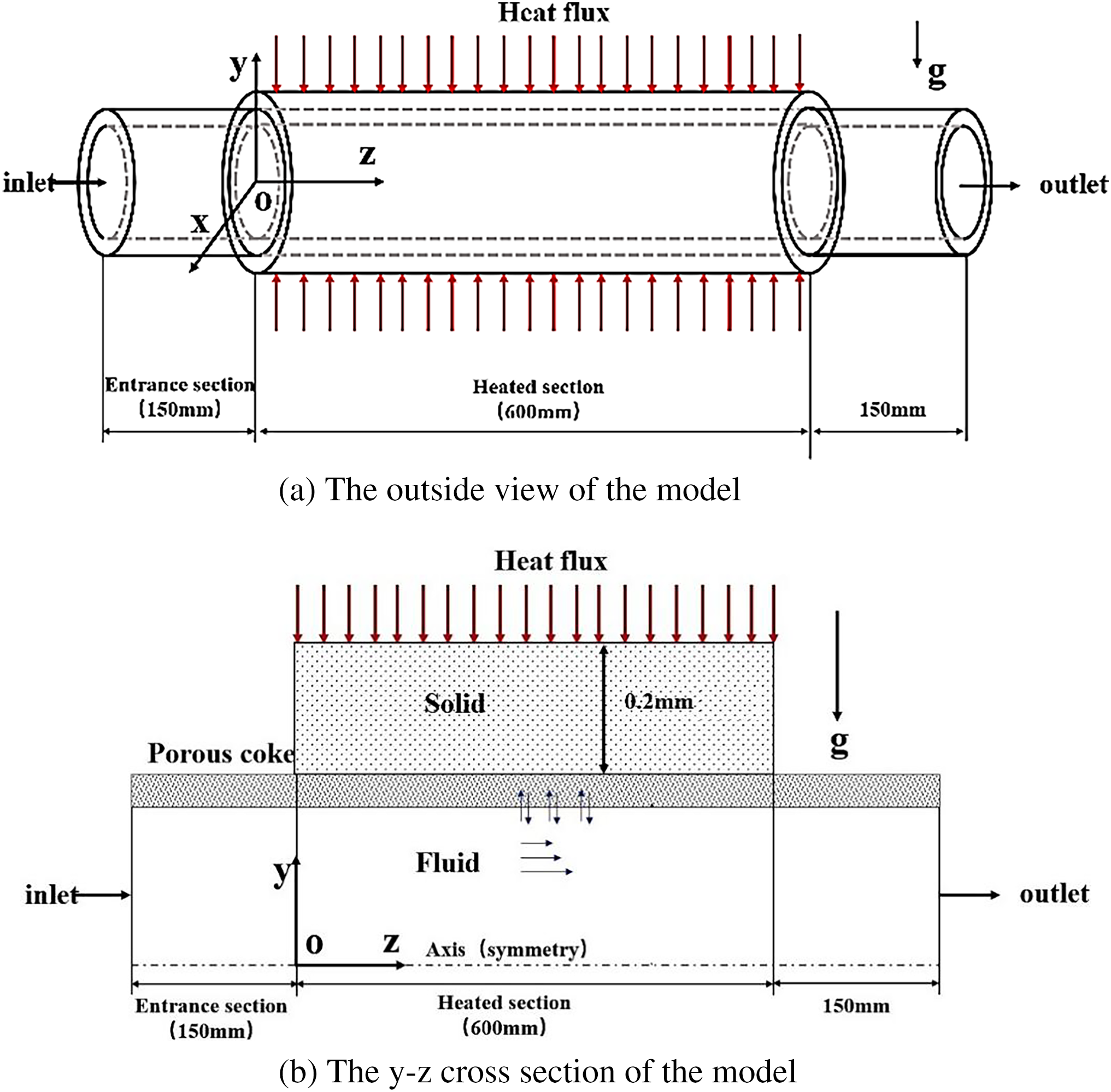
Figure 1: The physical model
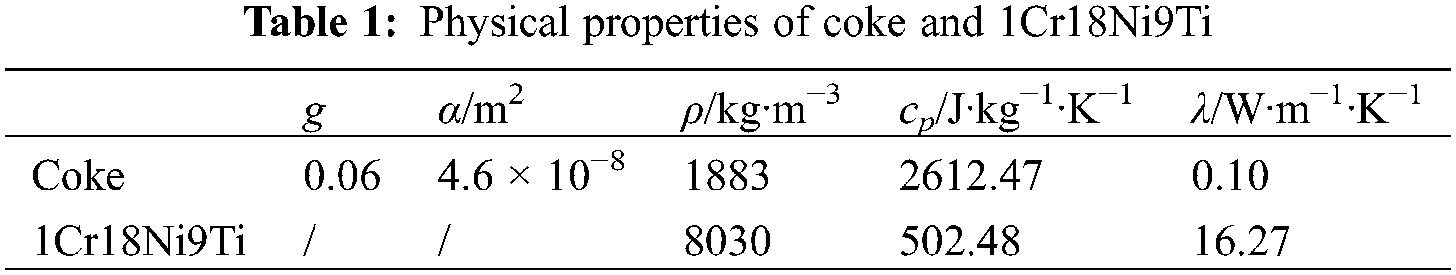
In the model, the fluid applied was supercritical Chinese aviation kerosene RP-3, and the wall of the regenerative cooling wall was 1Cr18Ni9Ti. As mentioned in the introduction, the coke of aviation kerosene is normally porous media. The porosity, apparent density, and permeability of the coke layer referred to Gascoin et al.’s results [4]. The properties of coke and 1Cr18Ni9Ti are illustrated in Table 1.
Aviation kerosene RP-3 is a complex mixture composed of various components. To simplify the calculation process, RP-3 was regarded as a simple substance rather than a complicated mixture. The physical properties of RP-3 were from Yu et al.’s research [25], as presented in Fig. 2.
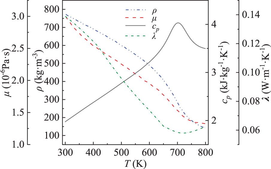
Figure 2: Physical properties of RP-3 at 5 Mpa [25]
The governing equations of RP-3 are presented as following:
where
The pores in the coking layer formed in the supercritical regeneration cooling channel were much smaller than the channel size, so the porous media model was used to simplify the treatment, without considering the details of the flow between pores. The porous media model was obtained by adding a momentum source term of the momentum equation to the standard flow equation. C2 was inertial resistance coefficient, and the local thermal equilibrium model was applied to solve the heat transfer of porous media.
To simulate the turbulent flow, an enhanced wall treatment was used in RNG k-ε model. Values of C1e, C2e and C3e were 1.42, 1.68 and 0.0845, respectively.
αk and αε represented the effective Prandtl numbers corresponding to k equation and ε equation, respectively. αk = αε ≈ 1.393. μ was the effective viscosity. Gk and Gb were production of turbulence kinetic energy generated from average velocity gradient and buoyancy force. Sε and Sm were source items.
The governing equation of the solid phase was the equation of heat conduction:
Unless otherwise specified, the boundary conditions were set as follows: the flow rate at the mass flow inlet was qm = 3 g/s, and the temperature of the mass flow inlet remained at Tin = 400 K. The type of outlet was a pressure outlet of p = 5 MPa. The constant heat flux imposed on the tube wall was normally q = 400 kW/m2. Coupled heat transfer occurred at the interface where the channel wall and the coke layer intersected. The junction of the coke layer and aviation kerosene was the interface boundary. Besides, the no-slip conditions were applied on other walls.
The simulation work was completed with the aid of the commercial software ANSYS FLUENT 18.0. The governing equations were discretized by the finite volume method, and the convection terms and diffusion terms were discretized by the QUICK scheme. The pressure and velocity coupling equations were solved by the SIMPLEC algorithm. When judging the convergence, the convergence criterion of the energy equation was set to 10−8, and other parameters were 10−6. The schematic diagram of the grid structure is presented in Fig. 3.
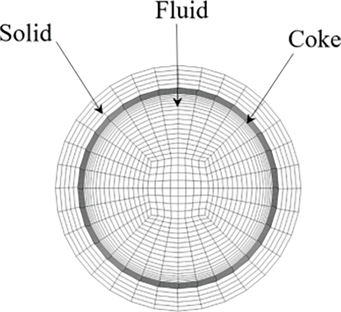
Figure 3: Schematic diagram of the grid structure
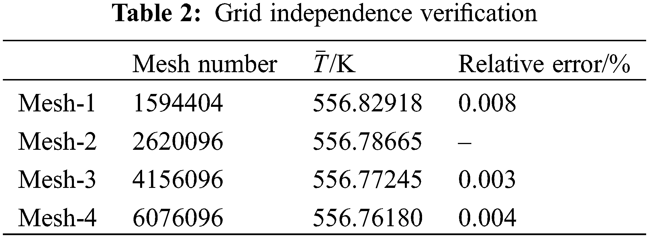
Before the model validation, the grid independence verification was conducted, and the bulk temperatures at the outlet obtained from different grids were compared in Table 2. Considering the accuracy and the efficiency, Mesh-2 was selected to complete the following simulation work.
To verify the porous model, the wall temperature of the heated aluminum tube with porous aluminum foam was calculated. The data acquired from the computational model were compared with the results from Dukhan et al.’s experiment [26] and are demonstrated in Fig. 4a. The variation trend was consistent, and the largest deviation was only 0.74%. To verify the numerical model dealing with supercritical RP-3, the inner wall temperatures obtained from Zhang et al.’s [27] experiment and our model were compared and are shown in Fig. 4b, with the maximum deviation being 4.7%. The numerical model and the method applied are reliable for the present work.
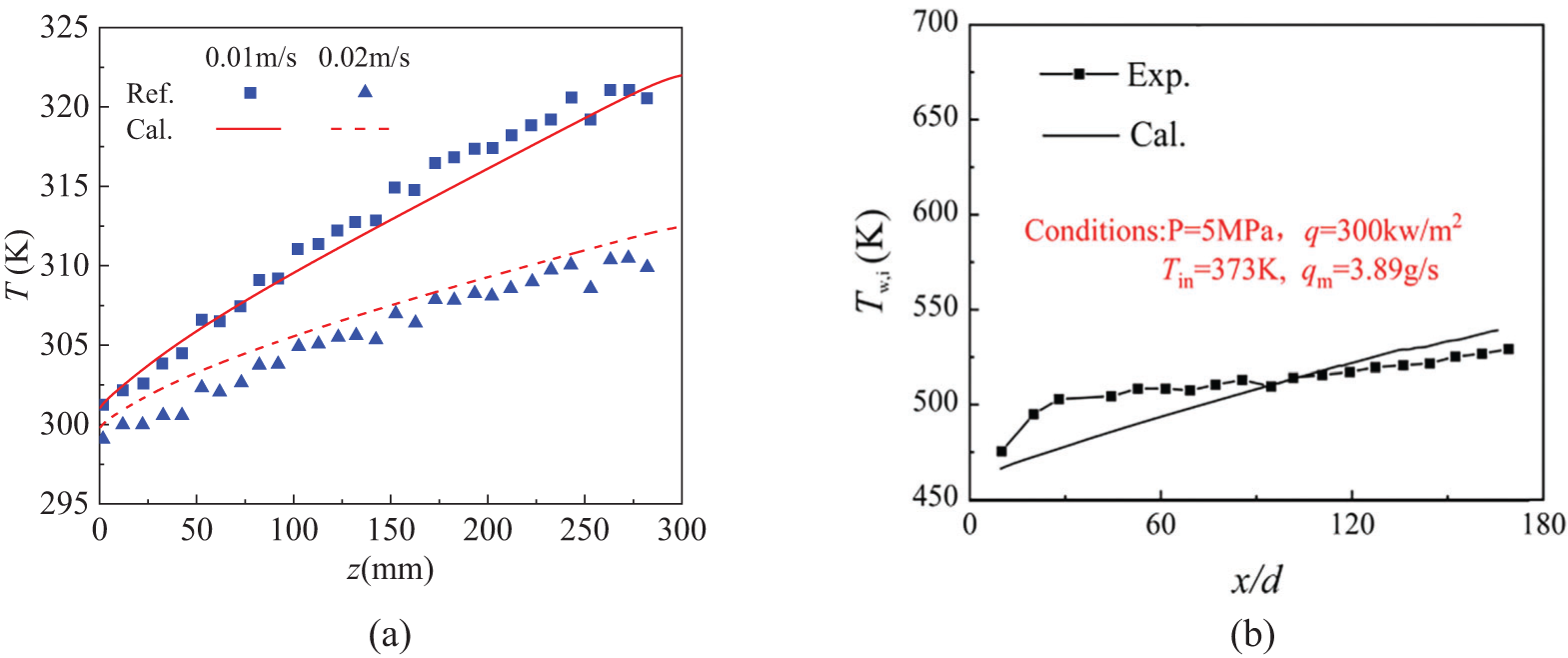
Figure 4: Comparison between calculation results with experimental results. (a) comparison with results from [26], (b) comparison with results from [27]
3.1 The Influence of Coke Layer Thickness
Fig. 5 presents the temperature distribution on the y-z section of x = 0 mm with different coke layer thicknesses. As can be seen from the Figure, RP-3 inside the coke layer normally had a higher temperature than RP-3 outside the coke layer. The coke layer hindered the flow of RP-3, causing it to absorb more heat from the heating wall and then a rise in the wall temperature. The temperature of the mainstream fluid showed a growing trend along the flow direction by continuously absorbing heat from the high-temperature wall.
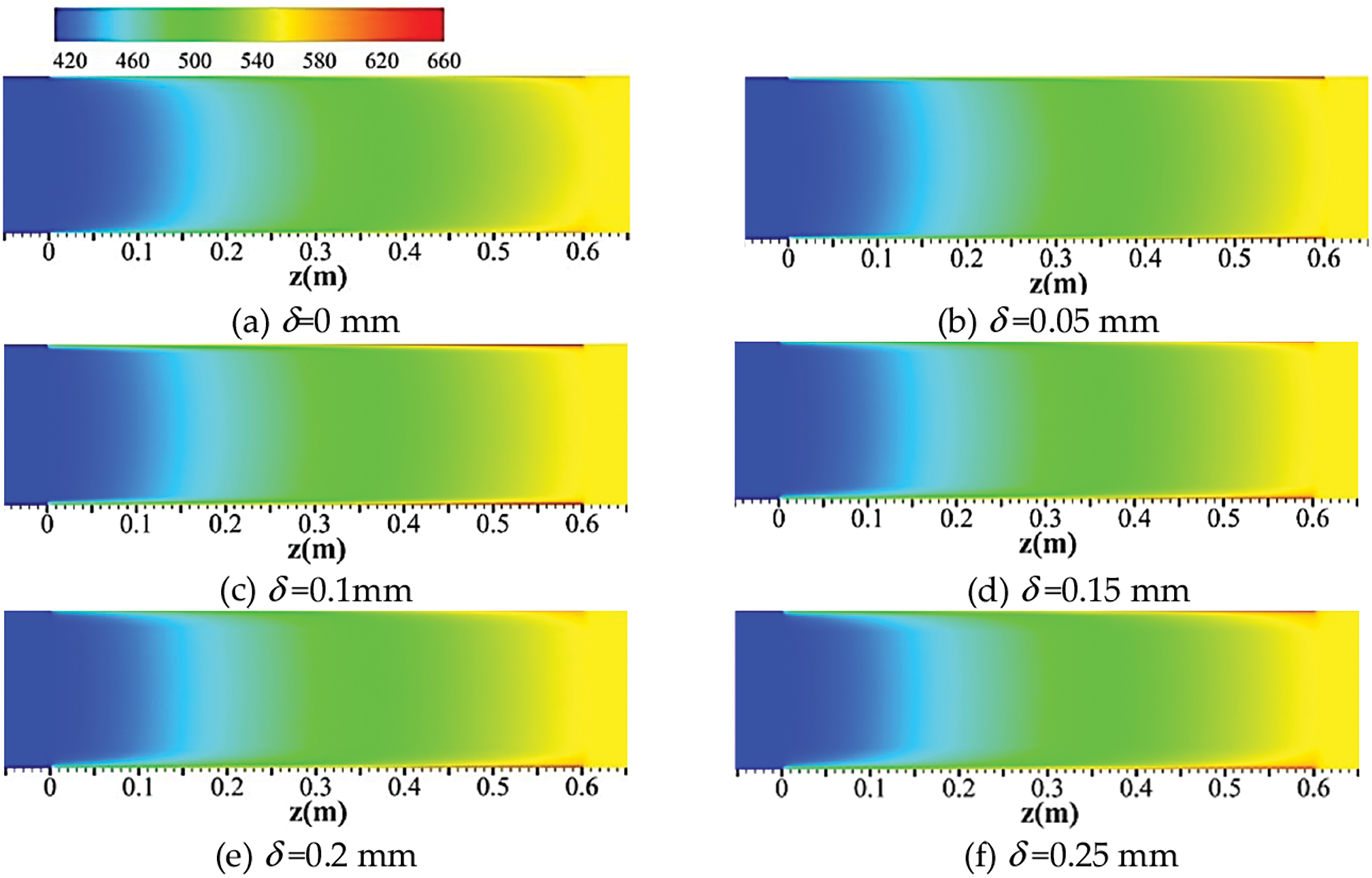
Figure 5: The temperatures of the cross-section (x = 0 mm) in the cooling channel at different coke layers
Fig. 6 quantitatively illustrates the variation of kerosene bulk flow temperature and the channel wall temperature. Here, the bulk flow temperature was defined as
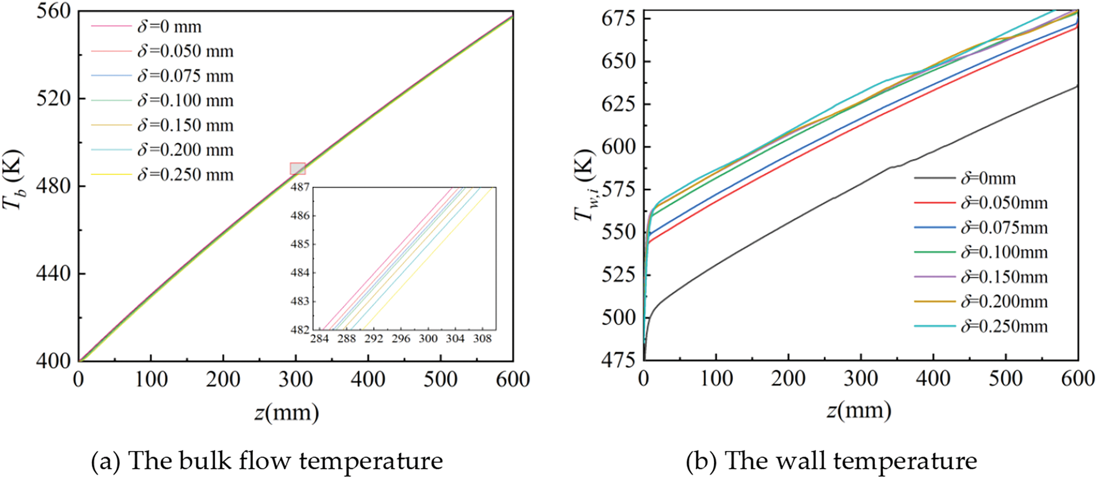
Figure 6: The temperature distributions at different coke layers
It is noted that when we increased δ beyond 0.1 mm, the impact of layer thickness variation on the wall temperature became minor. With the increase of δ, the deterioration of heat transfer caused by the increasing thermal resistance and heat transfer enhancement stemmed from flow acceleration co-affected the wall temperature. The coke layer hindered the flow of RP-3, causing it to absorb more heat from the heating wall and lead to a temperature rise. When δ increased to a certain level, heat transfer enhancement and deterioration reached equilibrium, and the temperature drop caused by heat transfer enhancement offset the temperature rise. Thus, in the range of 0.15~0.2 mm, the wall temperature varied slightly when the coke layer thickened. It should be emphasized that when the temperature of the channel wall was above 600 K, the wall temperature decreased slightly and then continued to increase, which was owing to the property variation of supercritical RP-3.
Fig. 7 shows the radial temperature distribution at z = 150 mm and z = 450 mm in the x-y section. In the zone away from the channel wall, the temperature value of RP-3 in the coking channel was slightly larger than that in the smooth channel and maintained at a relatively constant value. The fluid in porous coke stopped and could be heated for a long while. Accordingly, the radial temperature of kerosene experienced a dramatic increase in the area adjacent to the coke layer. Due to varying layer thickness, the positions of the sudden rise were evident.
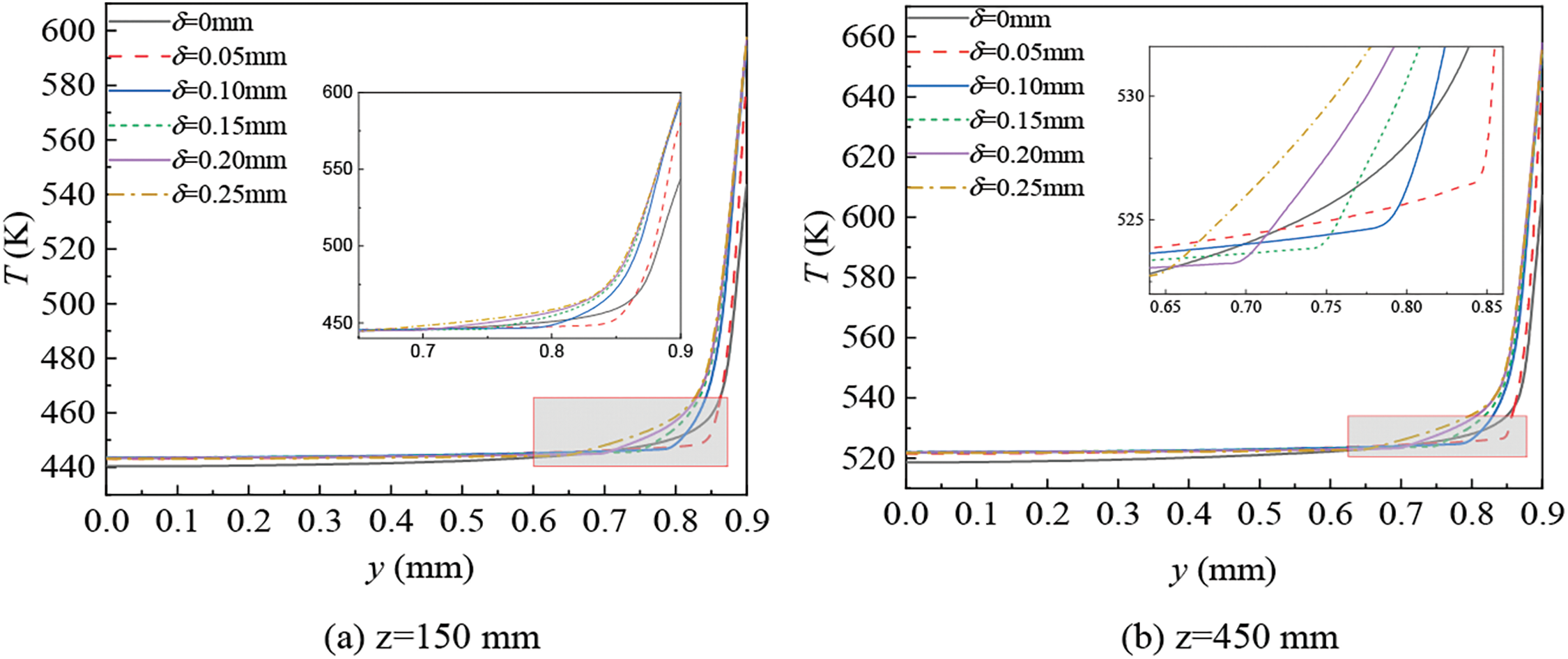
Figure 7: The temperature distributions in the radial section
Fig. 8 presents the velocity distribution in the y-z section when x = 0 mm and was at different coke layer thicknesses. It is emphasized that the existence of the coke layer caused a discrepant velocity field. When δ = 0 mm, the velocity magnitude on the y-z section was uniform, but an apparent magnitude difference appeared in the coking channel. The velocity magnitude of RP-3 near the center line increased along the flow direction and formed a cone-shaped or trapezium-shaped velocity magnitude distribution. When the coke layer thickened, the conical tip gradually extended to the inlet. Because coke was porous media, the existence of pores increased the roughness of the coke layer and slowed down the fluid near the coke. As it shows, the flow velocity of RP-3 in the middle part increased as the coke layer thickened. The primary reason for the variation was the reduction in the cross-section of the channel. In the coking channel, kerosene had a larger velocity magnitude in the region near the outlet, which was ascribed to the density decrease of RP-3 when a continuous heat absorption from the wall occurred. The porosity of the coke layer was relatively low, so the flow inside the coke was too weak to be noticed directly.
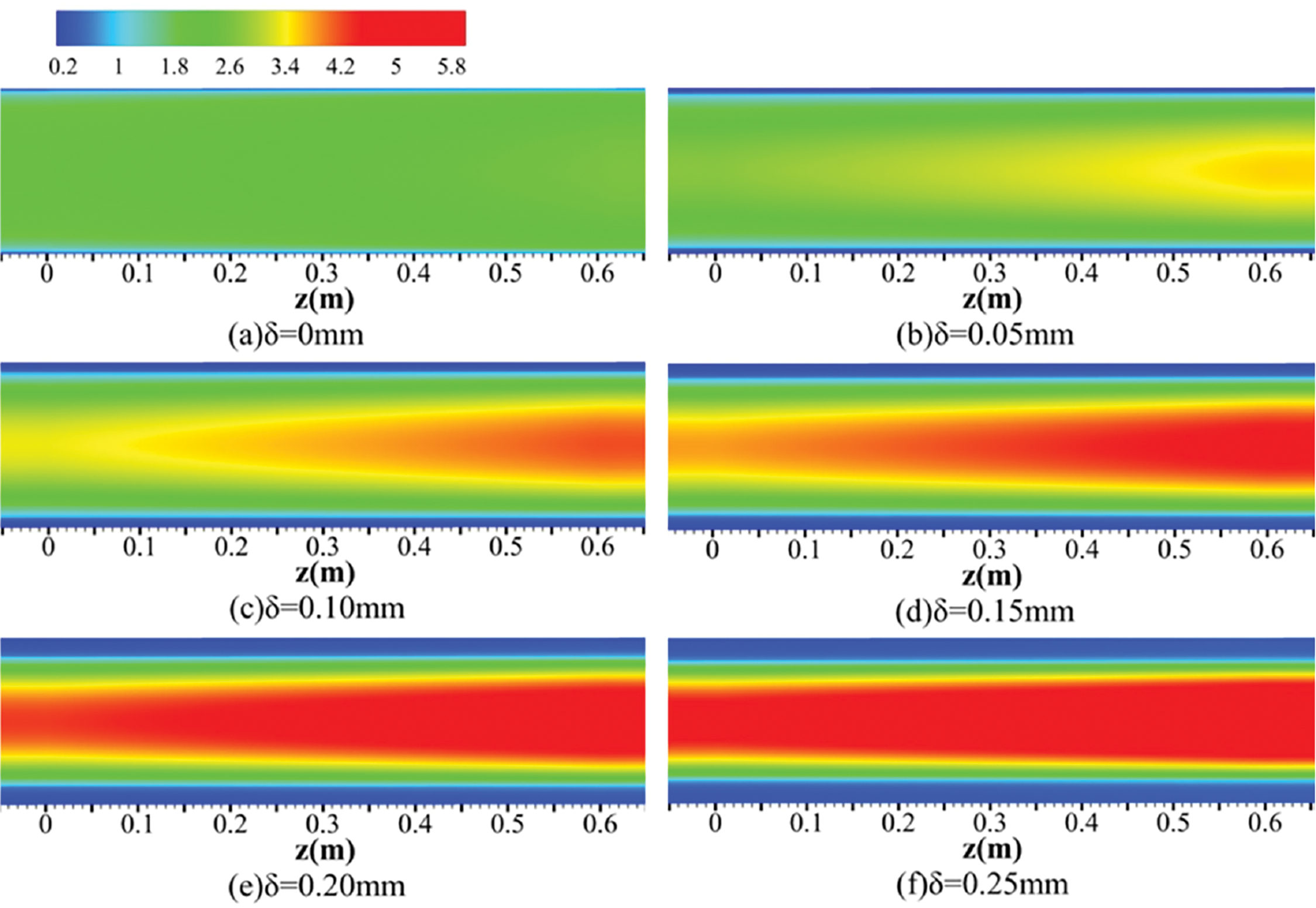
Figure 8: The velocity magnitudes in the y-z section of x = 0 mm at varied coke layer thicknesses
The pressure drop along the channel center line and between the inlet and the outlet is illustrated in Fig. 9. The pressure drop was defined as
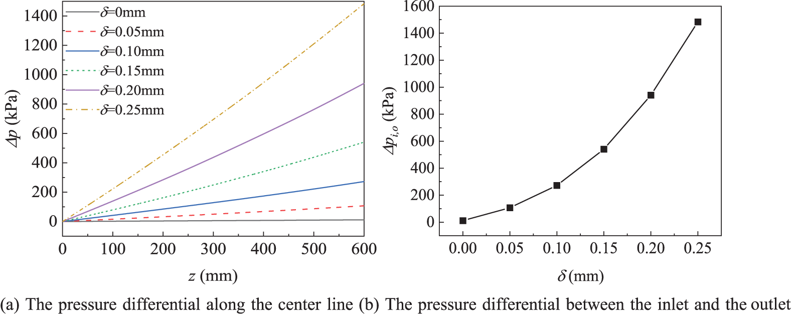
Figure 9: The pressure difference at different coke layers
The radial velocity of RP-3 on the z = 150 mm section is shown in Fig. 10. The radial velocity was defined as
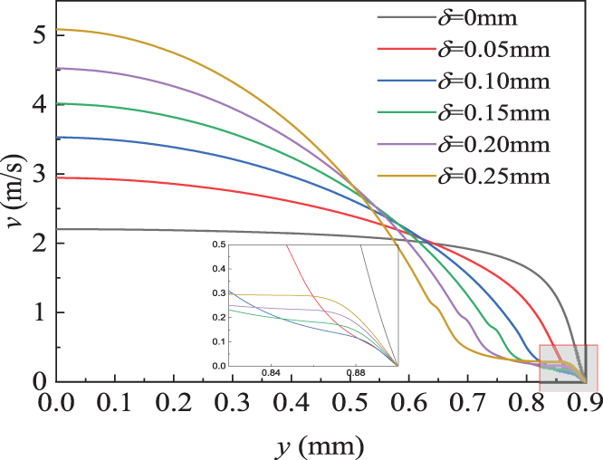
Figure 10: The velocity magnitudes in the radial-section of z = 150 mm
Fig. 11 shows the distribution of the local heat transfer coefficient h as well as the average heat transfer coefficient
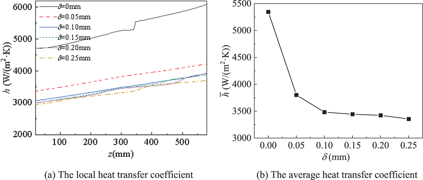
Figure 11: The distribution of the heat transfer coefficient at different coke layers
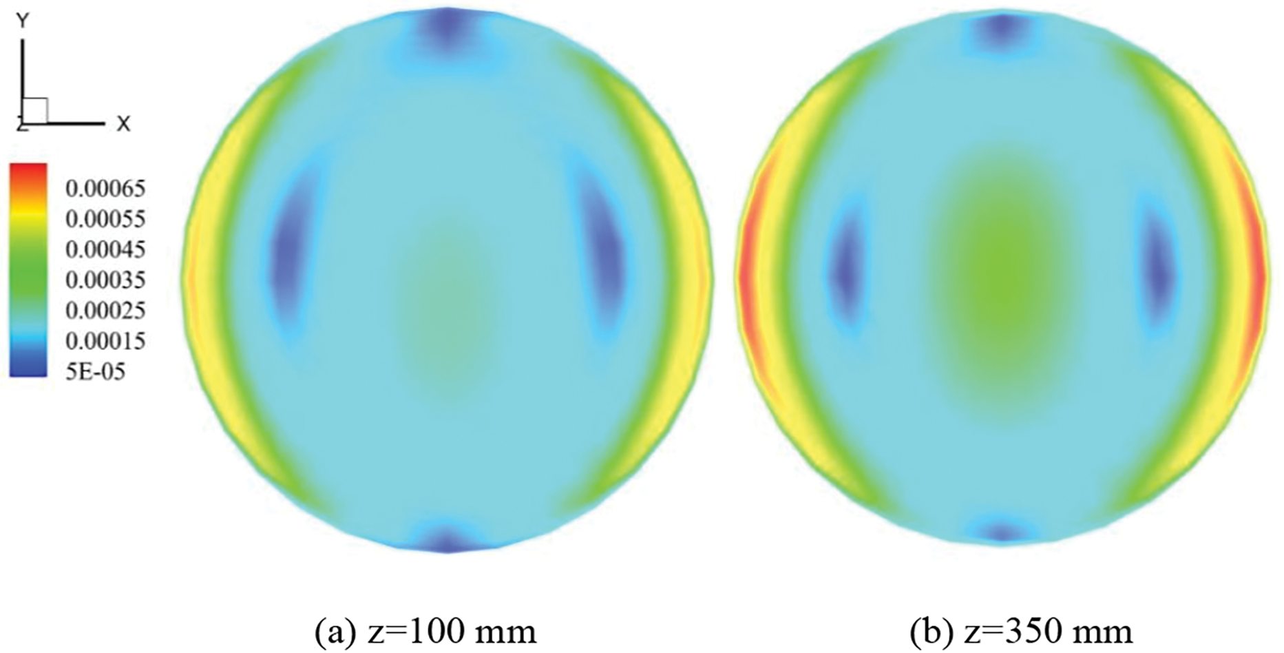
Figure 12: The velocity distributions of the section
3.2 The Influence of Inlet Mass Flow Rate
According to Fig. 13, the fluid temperature decreased as the flow rate increased. To quantify the impact of the inlet mass flow rate, a line graph of the bulk flow temperature, as well as the inner wall temperature along the flow direction, are presented respectively in Fig. 14. As depicted in the diagram, the temperature of RP-3 and the inner channel wall temperature increased as the inlet flow slowed down, which was caused by the weakening of energy exchange between the fluid and the channel wall because of the velocity reduction. Coke often led to the wall temperature rise, and the wall temperature difference between the coke-depositing channel and the smooth channel was most likely to be larger at a higher mass flow rate.
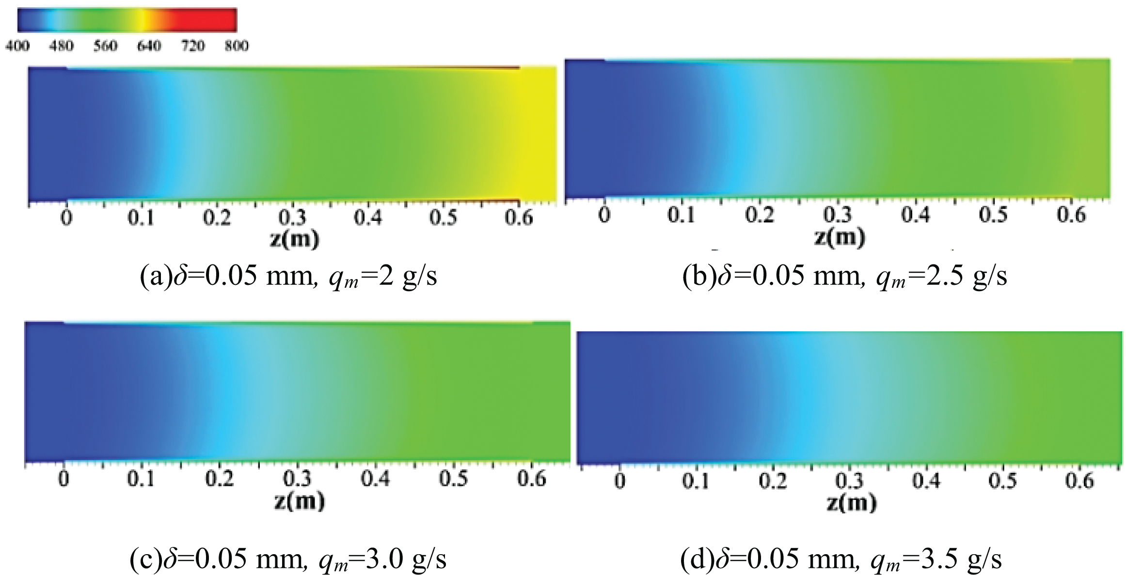
Figure 13: The temperatures of the y-z section (x = 0 mm) at various mass flow rates
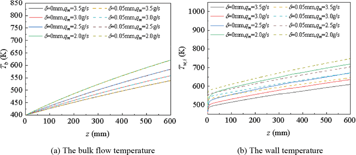
Figure 14: The temperature distributions at various mass flow rates
Fig. 15 shows that RP-3 velocity inside the coke layer and outside both increased when the mass flow accelerated. Fig. 16 illustrates the variation of the inlet and outlet pressure differential with qm. In contrast, pressure drop in the coking channel with inlet flow acceleration appeared more drastic, and it was more noticeable at a large mass flow rate when there was a coke layer. The reason for the difference was the increase in flow friction caused by coke.
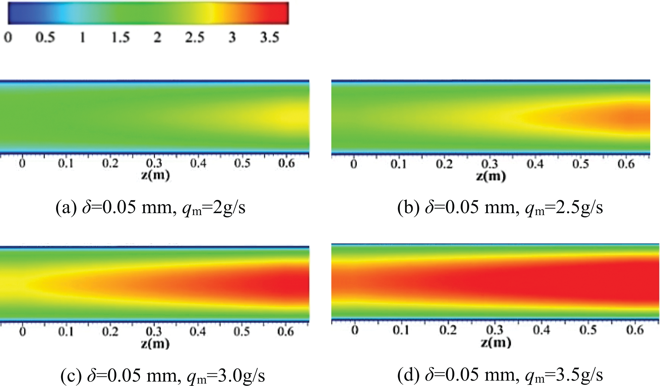
Figure 15: The velocity magnitudes of the y-z cross-section (x = 0 mm) in the cooling channel at different mass flow rates
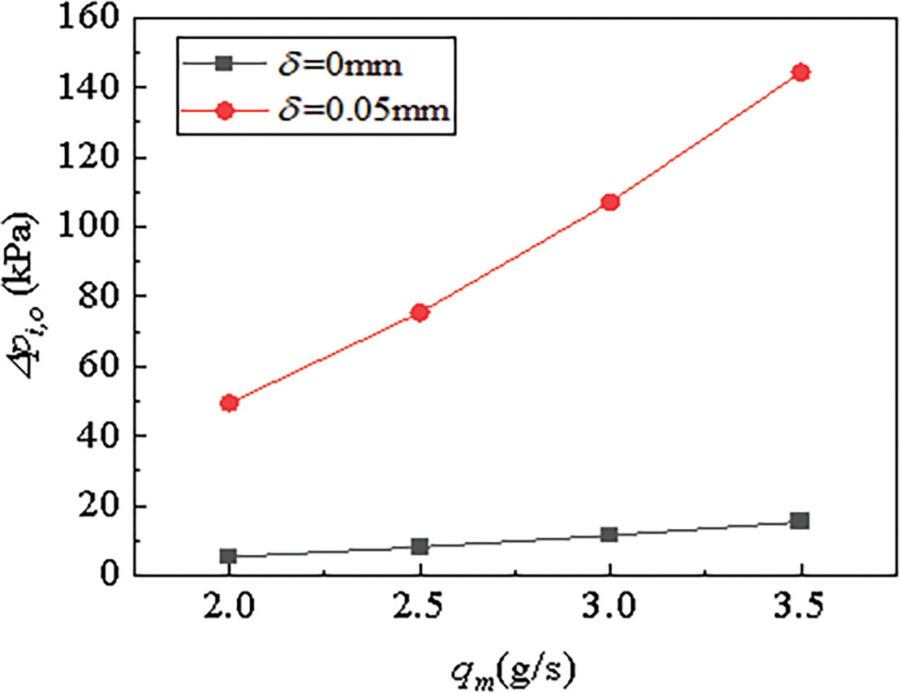
Figure 16: The distributions of the pressure differential between the inlet and the outlet at various mass flow rates
As plotted in Fig. 17, heat transfer was intensified by increasing the inlet mass flow rate. However, the impact of the inlet flow rate variation on heat convection was far more remarkable in the channel without coking. A ladder-like increase in the local heat transfer coefficient was also observed when δ = 0.05 mm. The average turbulent kinetic energy was computed in Fig. 18 to explain the variation. The slope of kinetic variation rose at the position where the ladder-like increase in h appeared.
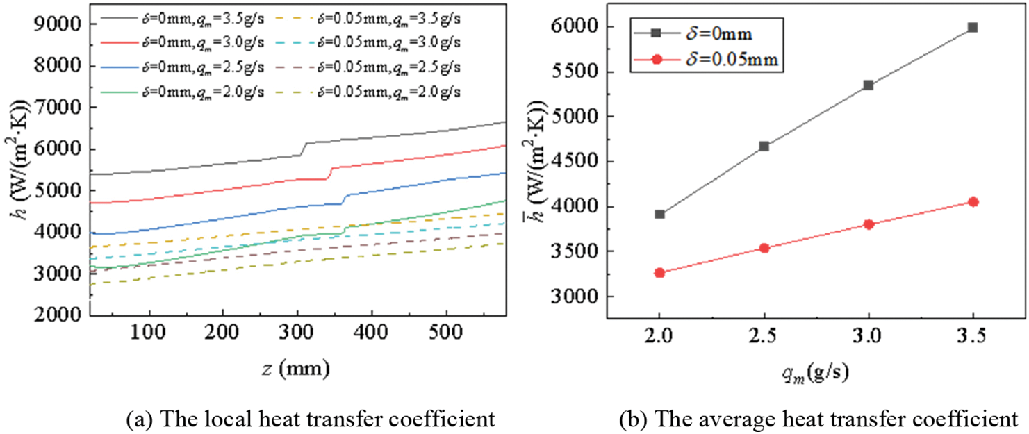
Figure 17: The variations of the local heat transfer coefficient at mass flow rate
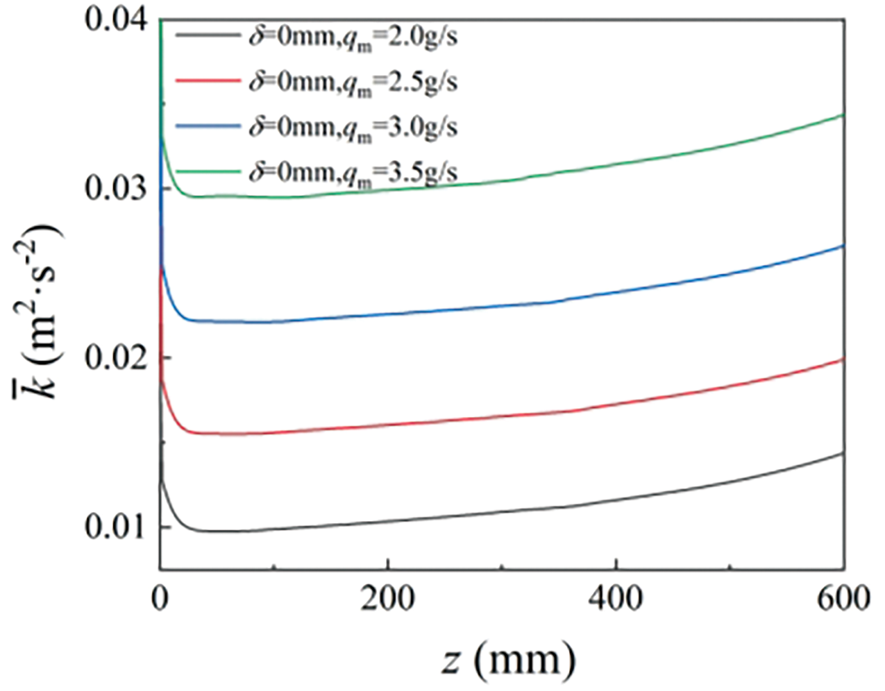
Figure 18: The turbulent kinetic energy variations along the channel at different inlet mass flow rates
3.3 The Influence of Wall Heat Flux Density
As shown in Fig. 19, the temperature of the fluid and the temperature distribution along the fluid direction are presented in Fig. 20. The results show that when the heat flux density increased, both the fluid temperature as well as the wall temperature went up. Compared with the situation in which the effect of coke wasn’t considered, the coke layer exerted an influence on wall temperature rise.
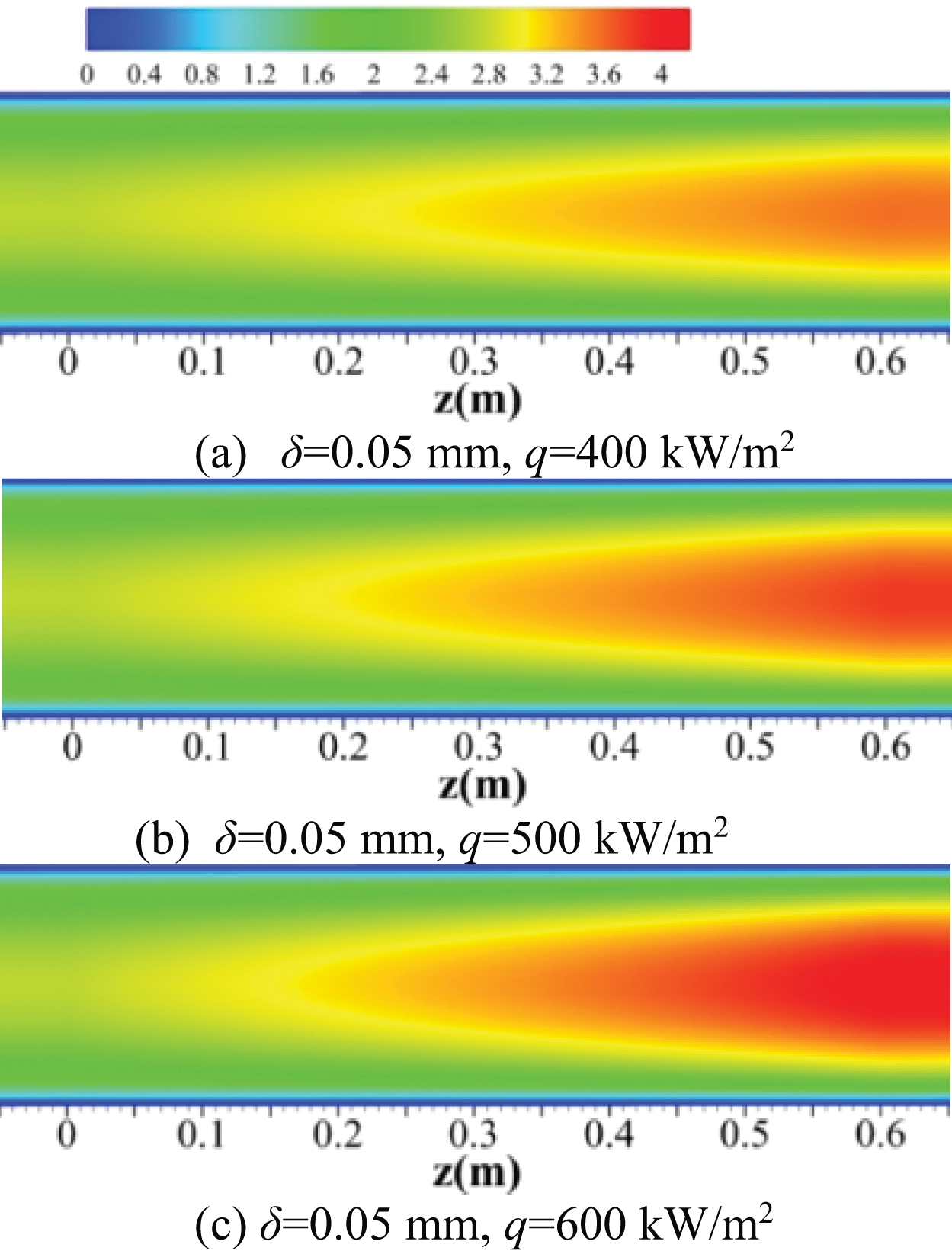
Figure 19: The temperatures of the y-z section (x = 0 mm) in the cooling channel at different heat fluxes
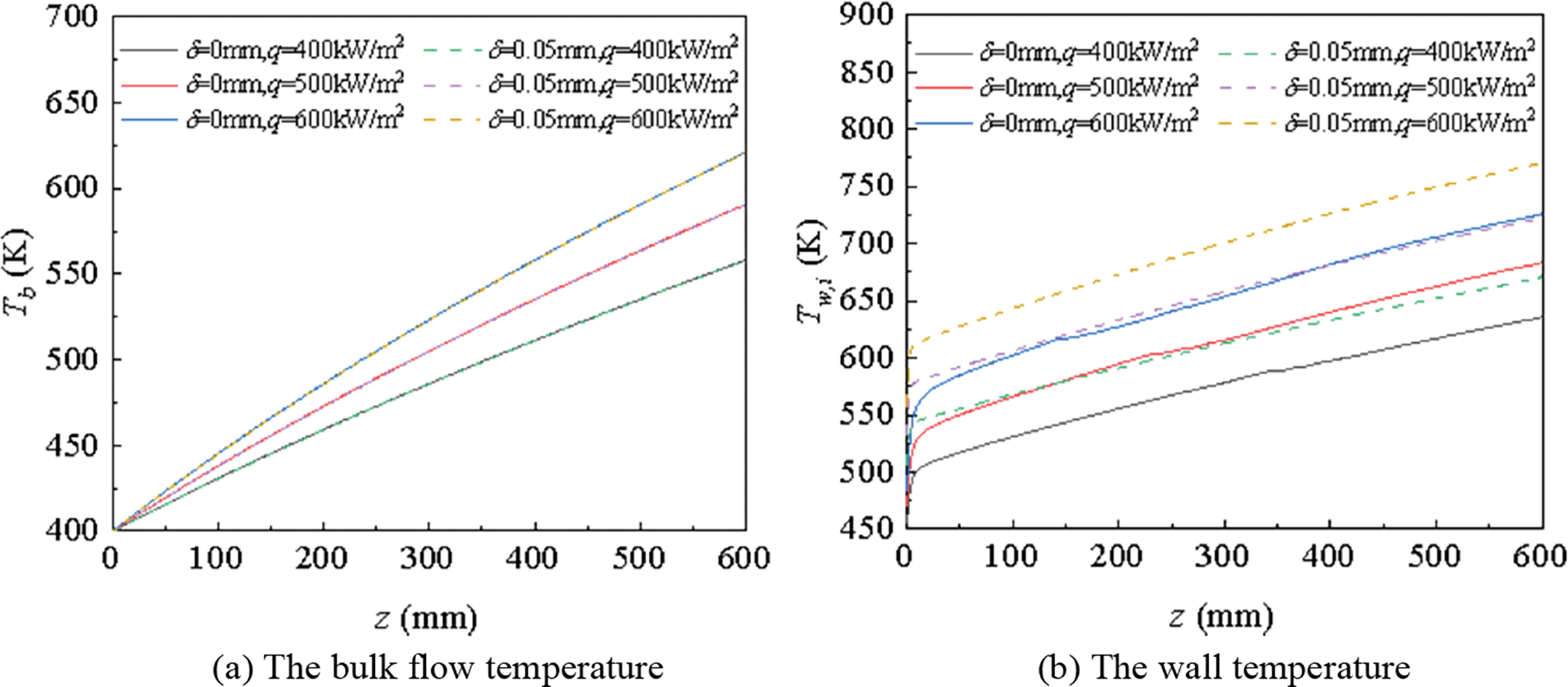
Figure 20: The temperature distributions at various heat flux densities
Fig. 21 demonstrates the comparison of velocity distributions in the coking channel at various heat fluxes. As flux density increased, RP-3 velocity inside the channel and the coke layer all grew. The pressure drop between the inlet and the outlet under different heat fluxes is listed in Table 3. Between the two situations, the variation of pi,o with heat flux was evident. pi,o of the smooth channel reduced when the heat flux density increased, but pi,o of the channel with the coke layer became larger while the heat flux density mounted. The variation of pi,o in the smooth channel accounted for the reduction of fluid viscosity with rising temperature. The rising temperature of RP-3 and the reduction of the viscosity led to an increase in the flow velocity, so the pressure drop was reduced. In the coking channel, the coke layer played a significant role in increasing p as heat flux increased, and the fundamental reason for the variation lay in the increase of flow resistance caused by the porous coke layer.
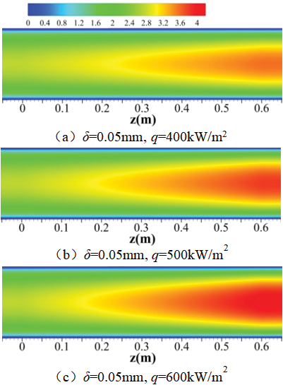
Figure 21: The velocity magnitudes of the y-z section (x = 0 mm) in the cooling channel at different heat fluxes
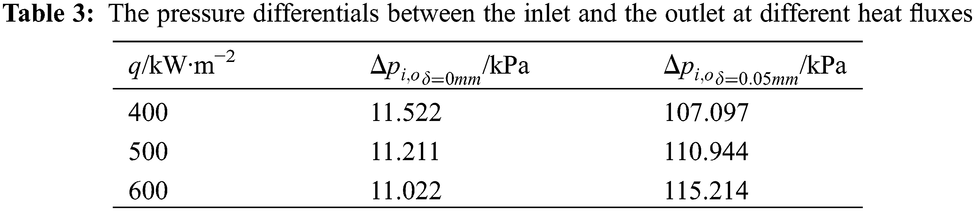
Table 4 compares
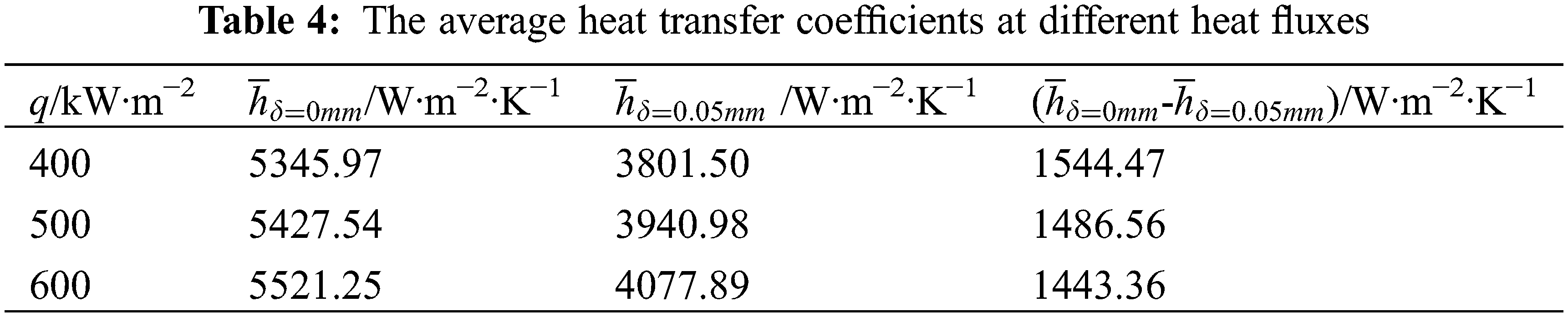
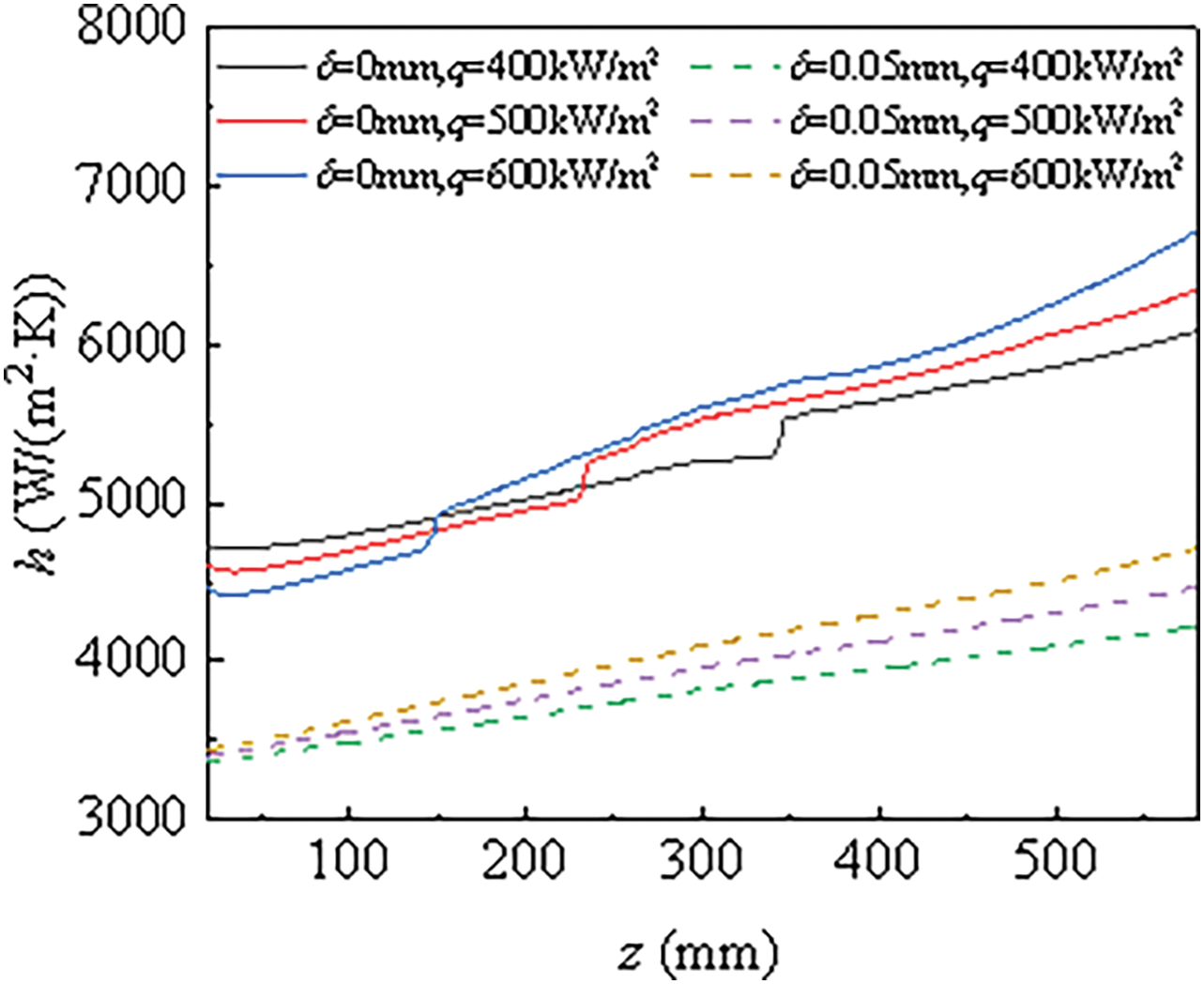
Figure 22: The distributions of the local heat transfer coefficient at different heat fluxes
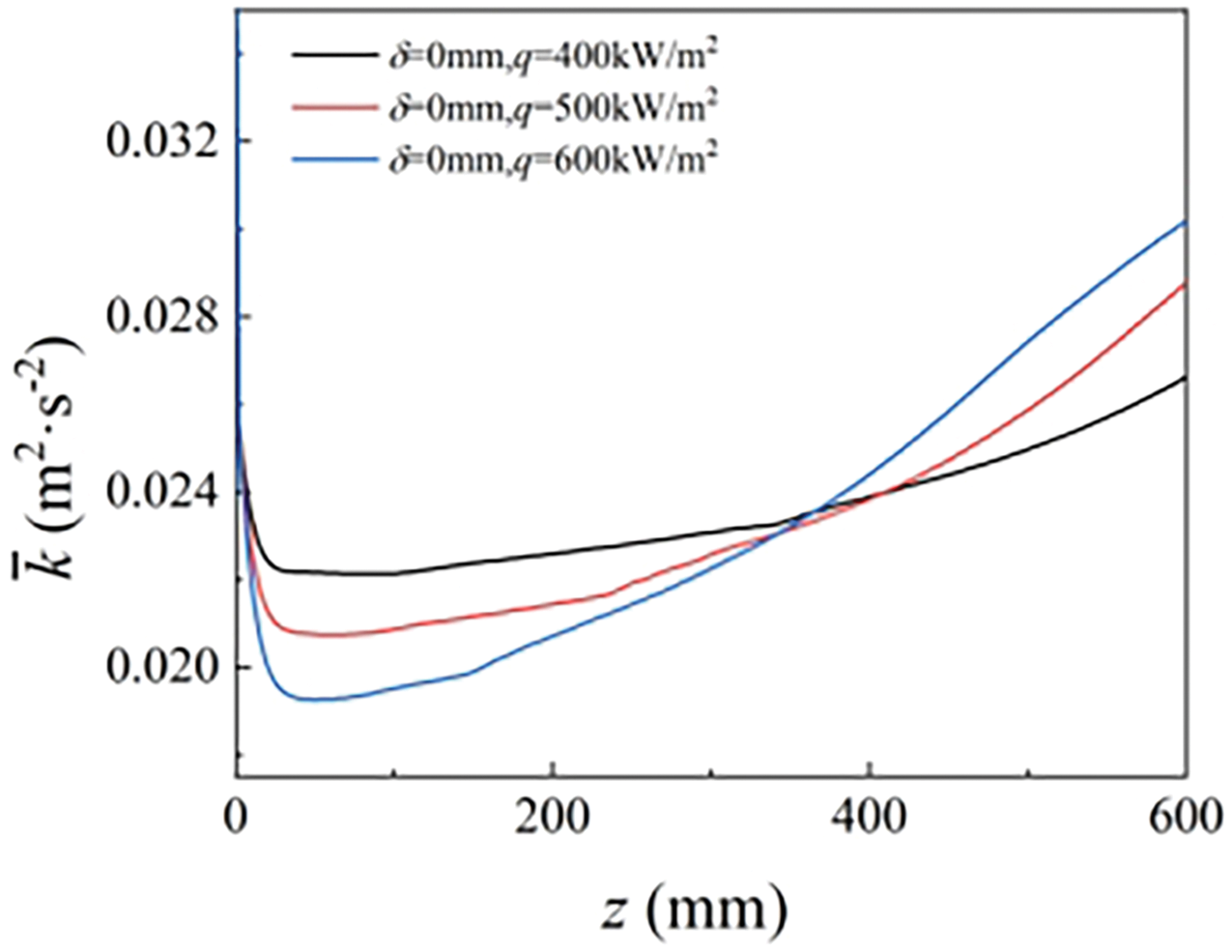
Figure 23: The turbulent kinetic energy variations along the channel at different heating fluxes
To find out the influence of the coke layer in the regenerative cooling channel on heat convection characteristics, several simulation work considering the coke layer as porous media were carried out in the manuscript. Additionally, heat transfer and flow processes with and without coke were compared under various inlet mass flow rates as well as heat flux densities. Several conclusions were reached as follows:
1. The existence of the coke layer has a nonnegligible effect on the temperature distribution and velocity of RP-3. The coke layer generally weakens the heat transfer of RP-3, but the weakening effect is not reinforced by the thickening of coke layers. When heat transfer enhancement that is caused by the flow acceleration and heat transfer deterioration that results from a thermal resistance increase reaches a balance at a certain thickness of the coke layer, the heat transfer coefficient tends to be stable. A steep rise in the local heat transfer coefficient that is led by the buoyancy effect is observed only in the channel without coking.
2. Heat transfer inside the smooth channel is less sensitive to the acceleration of the inlet mass flow, but both the average heat transfer coefficient inside the smooth channel and the coking channel increase with the flow rate. The heat transfer capacity varies slightly in the inlet flow velocity between the smooth channel and the coking channel. The increase in the inlet mass flow rate leads to an obvious rise in the pressure differential between the inlet and the outlet, but the pressure differential in the smooth channel mounts slowly.
3. The increasing heat flux makes a minor difference in the heat transfer of the coking channel and the smooth channel. The results show that the increase in the heat flux density will reduce the pressure differential between the inlet and the outlet in the smooth channel but make the pressure drop of the coking channel rise, which is due to the increased flow resistance caused by coke.
Though the effect of the coke layer on heat transfer and flow characteristics of RP-3 has been discussed in the paper, the numerical results are not the same as the actual situation. In future research, we will focus on improving the accuracy of the computational model that takes the crack of RP-3, the non-uniform thickness of the coke layer along the channel, and so on into consideration.
Acknowledgement: We appreciate for the rigorous contribution made by Dan-Dan Cui to improve the quality.
Funding Statement: The research is funded by Natural Science Foundation of Chongqing (No. CSTB2022NSCQ-MSX0416), Open Fund of State Key Laboratory of Oil and Gas Reservoir Geology and Exploitation (Southwest Petroleum University) (No. PLN2020-8), Open Fund of Chongqing Key Laboratory of Fire and Explosion Safe (No. LQ21KFJJ02), Open Fund of State Key Laboratory of High Temperature Gas Dynamics (No. 2021KF14), Sichuan Science and Technology Program (No. 2022YFH0017).
Author Contributions: Conceptualization, Jia-Jia Yu; Methodology, Jia-Jia Yu; Software, Shang-Zhen Yu; Validation, Shang-Zhen Yu; Formal Analysis, Yu Zhang; Investigation, Yu Zhang; Resources, Jia-Jia Yu; Data Curation, Shang-Zhen Yu; Writing—Original Draft Preparation, Yu Zhang, Shang-Zhen Yu; Writing—Review & Editing, Yu Zhang; Visualization, Yu Zhang, Shang-Zhen Yu; Supervision, Jia-Jia Yu; Project Administration, Jia-Jia Yu; Funding Acquisition, Jia-Jia Yu, Yu Zhang. All authors reviewed the results and approved the final version of the manuscript.
Availability of Data and Materials: The data that support the findings of this study are available from the corresponding author upon reasonable request.
Ethics Approval: Not applicable.
Conflicts of Interest: The authors declare no conflicts of interest to report regarding the present study.
References
1. Xie WJ, Fang WJ, Li D, Xing Y, Guo YS, Lin RS. Coking of model hydrocarbon fuels under supercritical condition. Energy Fuels. 2009;23(6):2997–3001. doi:10.1021/ef8011323. [Google Scholar] [CrossRef]
2. Zhu J, Han HZ, Yang ZG, Luo W, Li XY. Numerical study on cross critical flow and heat transfer characteristics of regenerating cooling arc rib channel. Sci Tech Innov Her. 2020;17:51–4. [Google Scholar]
3. Han ZX, Zhou WX, Zan H, Jia ZJ, Martynenko S, Yanovskiy L. Numerical investigation on influences of inlet flow pattern on RP-3 thermal oxidation deposition. Fuel. 2021;303:121314. doi:10.1016/j.fuel.2021.121314. [Google Scholar] [CrossRef]
4. Gascoin N, Gillard P, Bernard S, Bouchez M. Characterisation of coking activity during supercritical hydrocarbon pyrolysis, fuel process. Technol. 2008;89:1416–28. [Google Scholar]
5. Ji PF, Zhang JY, Yuan C, Luo D, He XM. Physical properties of coke from the RP-3 kerosene. J Aerospace Power. 2018;33:1880–5. [Google Scholar]
6. Lucas P, Marchand A. Pyrolytic carbon deposition from methane: an analytical approach to the chemical process. Carbon. 1990;28:207–19. [Google Scholar]
7. Tevelde J, Spadaccini L, Szetela E. Thermal stability of alternative aircraft fuels. In: 19th Joint Propulsion Conference, 1983; Seattle, WA, USA. [Google Scholar]
8. Pioro IL, Duffey RB. Experimental heat transfer in supercritical water flowing inside channels (survey). Nucl Eng Des. 2005;235:2407–30. [Google Scholar]
9. Yamagata K, Nishikawa K, Hasegawa S. Forced convective heat transfer to supercritical water flowing in tubes. Int J Heat Mass Transf. 1972;15:2575–93. [Google Scholar]
10. Du Z, Lin W, Gu A. Numerical investigation of cooling heat transfer to supercritical CO2 in a horizontal circular tube. J Supercrit Fluid. 2010;55:116–21. [Google Scholar]
11. Li X, Zhang YX, Zhang SL. Effects of pyrolysis on heat transfer enhancement for hydrocarbon fuel flow in unilateral heated channels with dimples. Appl Therm Eng. 2022;218:119301. [Google Scholar]
12. Gong KY, Feng Y, Wu K, Qin J, Zhou CY. Buoyancy’s effect on heat and mass transfers of supercritical hydrocarbon fuel with pyrolysis in vertical circular tubes. J Propul Tech. 2022;43:163–74. [Google Scholar]
13. Gong KY, Cao Y, Feng Y, Zhang Y, Qin J. Flow and mass transfer of pyrolytic aviation kerosene in curved channel. J Thermophys Heat Transf. 2021;35(1):53–62. doi:10.2514/1.T5941. [Google Scholar] [CrossRef]
14. Pan H, Feng S, Liu ZH, Bi QC. Experimental investigation on the flow and heat transfer characteristics of aviation kerosene RP-3 during thermal pyrolysis coking. J Xi’an Jiaotong Univ. 2016;50:7–12. [Google Scholar]
15. Liu SY, Feng Y, Cao Y, Gong KY, Zhou WX, Bao W. Numerical simulation of supercritical catalytic steam reforming of aviation kerosene coupling with coking and heat transfer in mini-channel. Int J Therm Sci. 2019;137:199–214. doi:10.1016/j.ijthermalsci.2018.10.039. [Google Scholar] [CrossRef]
16. Yuan LG, Deng HW, Xu GQ, Jia ZX, Li YF. Effects of RP-3 coke deposition on heat transfer under supercritical pressure. J Aerospace Power. 2013;28:832–7. [Google Scholar]
17. Wang Y, Guo J, Deng HW, Huang HR, Jia ZX. Effects of RP-3’s wall coke deposition on flow resistance under supercritical pressure. J B Univ Aeronaut Astronaut. 2016;42:1250–5. [Google Scholar]
18. Fu YC, Wen J, Tao Z, Guo QX, Huang HR. Surface coking deposition influences on flow and heat transfer of supercritical hydrocarbon fuel in helical tubes. Exp Therm Fluid Sci. 2017;85:257–65. doi:10.1016/j.expthermflusci.2017.03.016. [Google Scholar] [CrossRef]
19. Feng Y, Gao Y, Liu SY, Qin J, Hemeda AA, Ma YB. The influence of coking on heat transfer in turbulent reacting flow of supercritical hydrocarbon fuels. Int J Heat Mass Transf. 2019;144:118623. doi:10.1016/j.ijheatmasstransfer.2019.118623. [Google Scholar] [CrossRef]
20. Sun X, Yuan Y, Tan T, Jing TT, Qin F, Meng H. Large eddy simulations of heat transfer and thermal oxidative coking of aviation kerosene in vertical U-tube at a supercritical pressure. Int J Heat Mass Transf. 2022;195:123205. [Google Scholar]
21. Li X, Du MM, Zhong FQ. Effect of dimple depth on turbulent flow and heat transfer of kerosene in rectangular duct. Acta Mech Sinica. 2022;38:337. doi:10.1007/s10409-021-09010-x. [Google Scholar] [CrossRef]
22. Jiang Y, Qin J, Chetehouna K, Gascoin N, Bao W. Effect of geometry parameters on the hydrocarbon fuel flow rate distribution in pyrolysis zone of SCRamjet cooling channels. Int J Heat Mass Transf. 2018;141:1114–30. doi:10.1016/j.ijheatmasstransfer.2019.07.054. [Google Scholar] [CrossRef]
23. Yu JJ, Jiang LB, Yu J, Yu BB, Li YR. Flow and heat transfer of supercritical RP-3 kerosene in an inclined rectangular channel heated on one side. Int Commun Heat Mass. 2022;133(6):105933. doi:10.1016/j.icheatmasstransfer.2022.105933. [Google Scholar] [CrossRef]
24. Wang YH, Lu YN, Li SF. Characteristics and critical criteria for unstable flow and heat transfer of RP-3 aviation kerosene in a vertical upward channel. J Eng Thermophys. 2022;43:685–92. [Google Scholar]
25. Yu J. Studies on the surrogate fuel methods for the simulation of reacting flows in combustion; Chongqing, China: Chongqing University; 2017. [Google Scholar]
26. Dukhan N, Bağcı Z, Özdemir M. Thermal development in open-cell metal foam: an experiment with constant wall heat flux. Int J Heat Mass Transf. 2015;85(15–16):852–9. doi:10.1016/j.ijheatmasstransfer.2015.02.047. [Google Scholar] [CrossRef]
27. Zhang CB, Xu GQ, Gao L, Tao Z, Deng HW, Zhu K. Experimental investigation on heat transfer of a specific fuel (RP-3) flows through downward tubes at supercritical pressure. J Supercrit Fluid. 2012;2:90–9. doi:10.1016/j.supflu.2012.07.011. [Google Scholar] [CrossRef]
Cite This Article
 Copyright © 2025 The Author(s). Published by Tech Science Press.
This work is licensed under a Creative Commons Attribution 4.0 International License , which permits unrestricted use, distribution, and reproduction in any medium, provided the original work is properly cited.
 Downloads
 Citation Tools