
 Submit a Paper
 Propose a Special lssue
 Open Access
ARTICLE

Numerical Analysis of Rotor Blade Angle Influence on Stall Onset in an Axial Fan
1 Department of Power Engineering, North China Electric Power University, Baoding, 071003, China
2 Zhejiang Rongda Yongneng Compressor Co., Ltd., Hangzhou, 310030, China
* Corresponding Author: Wei Yuan. Email:
Fluid Dynamics & Materials Processing 2025, 21(6), 1505-1528. https://doi.org/10.32604/fdmp.2025.061052
Received 15 November 2024; Accepted 14 February 2025; Issue published 30 June 2025
 View Full Text
 Download PDF
Abstract
This study explores the influence of rotor blade angle on stall inception in an axial fan by means of numerical simulations grounded in the Reynolds-Averaged Navier-Stokes (RANS) equations and the Realizable k-ε turbulence model. By analyzing the temporal behavior of the outlet static pressure, along with the propagation velocity of stall inception, the research identifies distinct patterns in the development of stall. The results reveal that stall inception originates in the second rotor impeller. At a blade angle of 27°, the stall inception follows a modal wave pattern, while in all other cases, it assumes the form of spike-type stall. The flow field associated with spike stall inception demonstrates a relatively uniform gradient in the radial direction, whereas the modal wave stall case displays a distinctive “L”-shaped propagation feature. At blade angles of −9° and −18°, multiple stall inceptions are observed. These phenomena initiate at the blade’s leading edge, propagate along both axial and radial directions, and transition dynamically between single and multiple inception states.Keywords
In the realm of turbomachinery turbocharging, adjustable-blade axial fans have gained widespread application in power plants, attributed to their exceptional efficiency, operational stability, and substantial capacity. The internal flow dynamics within these axial fans exhibit complex three-dimensional, viscous, and unsteady characteristics. Under conditions of reduced flow, the potential for instabilities, such as rotating stalls or even surges, may arise, resulting in flow degradation, heightened noise levels, and the peril of blade fractures. Consequently, during the design phase of axial fans, engineers are often compelled to strike a balance, sacrificing to some extent the pressure ratio and efficiency in favor of maintaining a robust margin between the fan’s design parameters and surge thresholds [1]. This strategic compromise ensures the safe and reliable operation of the machinery. Understanding the mechanisms that precipitate stall inception across varying rotor blade angles is of paramount importance for the proactive management of rotating stall phenomena and the refinement of axial fan design optimization strategies [2].
In 1955, Emmons et al. [3] pioneeringly introduced the concept of rotating stall, which arises when one or more blades encounter air separation or blockage, forming a distinct group. Following this foundational idea, Greitzer [4] leveraged approximation theory to develop a set of nonlinear third-order partial differential equation models, known as the M-G model, that capture the characteristic variations associated with rotating stall and surge-like motions in axial fans during transient stall events. Subsequently, numerous scholars, including Dazin et al. [5–7], embarked on diverse research trajectories to explore rotating stalls from various perspectives. Ohta et al. [8] experimentally highlighted the crucial role of cascade flow choking in determining surge behaviors. Sakata et al. [9] further conducted experimental research on the interplay between stall cells and surge behavior, revealing that the key factors influencing surge behavior are the “sudden alterations in the flow field near the peak point of unsteady characteristics and the rapid proliferation of stall cells during the stalling process”. The angle of blade installation in axial flow fan rotors exerts a significant influence on their performance and operational efficiency. In exploring the impact of blade installation angle on the performance of axial fans, numerous scholarly studies have indicated that the aerodynamic noise generated by the impeller is predominantly characterized by low-frequency noise, with the primary noise sources located at the leading edge and tip regions on the suction side of the blades [10]. Furthermore, numerical simulation methods were employed to investigate the unsteady flow characteristics of adjustable stator axial fans under stall conditions. The research findings reveal that aberrant blade installation angles lead to an initial increase in flow rate during the onset of stall, thereby precipitating the fan into an unstable state prematurely. Additionally, this study elucidates the trends in how the overall sound pressure level of aerodynamic noise within the fan varies with changes in the blade installation angle [11,12].
Numerous contemporary studies have focused on elucidating the characteristics of peak phenomena and the underlying fluid dynamic mechanisms responsible for their formation within core compressors [13–15] and fan blades [16,17]. Research indicates that the genesis of such disturbances is primarily attributed to aerodynamic effects at the blade tip, where airflow separation initiates from the leading edge (LE) due to high incidence angles. This phenomenon, even when observed on a single blade, is sufficient to initiate an unstable progression towards rotational stall. The vortices released from the separated flow are entrained into a vortex tube, which is bounded on one end by the suction surface of the blade and on the other by the casing, propagating circumferentially. The obstruction caused by the vortex flow within the passage further augments the incidence angles of adjacent blades, thereby establishing a positive feedback loop that fosters the propagation and amplification of instability. Kim et al. [18] conducted an investigation into the varied mechanisms that induce spikes on fan blades and discovered that the radial distribution of loading influences the ultimate dimensions of the stall cell. However, this distribution does not necessarily determine the sequence or pathway leading to the formation of spikes.
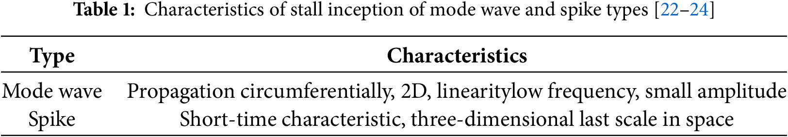
Furthermore, numerous scholars, including McDougall [19], Day [20,21], Khaleghi [22], among others, have conducted extensive research on stall inception, proposing various types such as Modal Wave, Spike, High-frequency stall, and Positioning stall [23,24]. Table 1 presents the characteristics of Modal Wave and Spike stall inception. Several studies have demonstrated that Modal Wave stall inception is characterized by large-scale, small-amplitude sine waves that evolve into stall cells after approximately 10 to 40 rotor revolutions (T). Notably, the rotational speed of Modal Wave stall inception is close to that of the stall cells. Conversely, Spike stall inception exhibits small-scale characteristics and evolves into complete stall cells within about 2 to 3 rotor revolutions. The rotational speed of Spike stall inception is higher than that of Modal Wave, accounting for approximately 70% of the rotor speed. During propagation, the scale and scope of Spike stall inception rapidly increase, and the rotational speed decreases following the development of stall cells [21–24].
Within the theoretical framework, meticulous observation of the characteristics of the incipient wave (i.e., the initial fluctuation triggering stall phenomena) offers a potential means to differentiate various stall inception modes [25–28]. However, in practical applications, the complexity of this process is considerably heightened due to the intertwined effects of multiple stall inception factors [29,30]. These factors are not only numerous but also exhibit extremely intricate individual mechanisms and coupled interactions, encompassing, among others, the range of tip clearance sizes, the onset and progression of endwall blockage, the degree of inlet flow field distortion, and variations in the rotational speed of components [31]. Minor alterations in these parameters can exert profound influences on both the initiation of stall and its subsequent evolution pathways [32]. Deviations that lead to increased pressure and efficiency losses are crucial, as they significantly narrow the stable operating range of the fan [33,34]. In response to this phenomenon, most scholars have proposed methods to suppress the amplification of stall precursors, thereby delaying the onset of rotating stall [35–38].
To deeply dissect and elucidate the intricate relationship between stall inception modes and the design principles and operational parameters of rotating machinery [39–41], this paper undertakes an in-depth investigation of these mechanisms using an axial fan with adjustable blades as a case study.
In this paper, a two-stage variable-pitch axial fan, which is prevalent in power plant applications, is selected as the subject of investigation. The fan comprises six primary components: the inlet collector, the first rotor (designated as Rotor 1), the second rotor (designated as Rotor 2), two stators (similarly labeled), and the outlet diffuser. A detailed three-dimensional geometric model of the axial fan, depicted in Fig. 1, is constructed using GAMBIT software. The specifications and parameters of the axial fan are thoroughly outlined in Table 2.
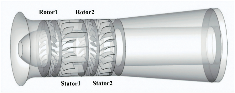
Figure 1: Geometric model of axial fan
The adjustable range of blade angles for the two-stage axial fan with movable blades spans from −18 degrees to 27 degrees. With the exception of the design rotor blade angle of 3°, intervals of nine degrees are employed across this range, resulting in six specific angles labeled
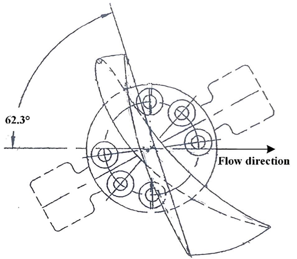
Figure 2: Diagram of geometric position of rotor blade angle
The present research focuses on elucidating the mechanism by which variations in rotor blade angle affect the inception of stall. It emphasizes a comparative analysis of the temporal characteristics of outlet static pressure, as well as the initiation and propagation velocities of stall cells. Furthermore, the study proposes distinct modes of stall inception. These specific processes are illustrated in Fig. 3.
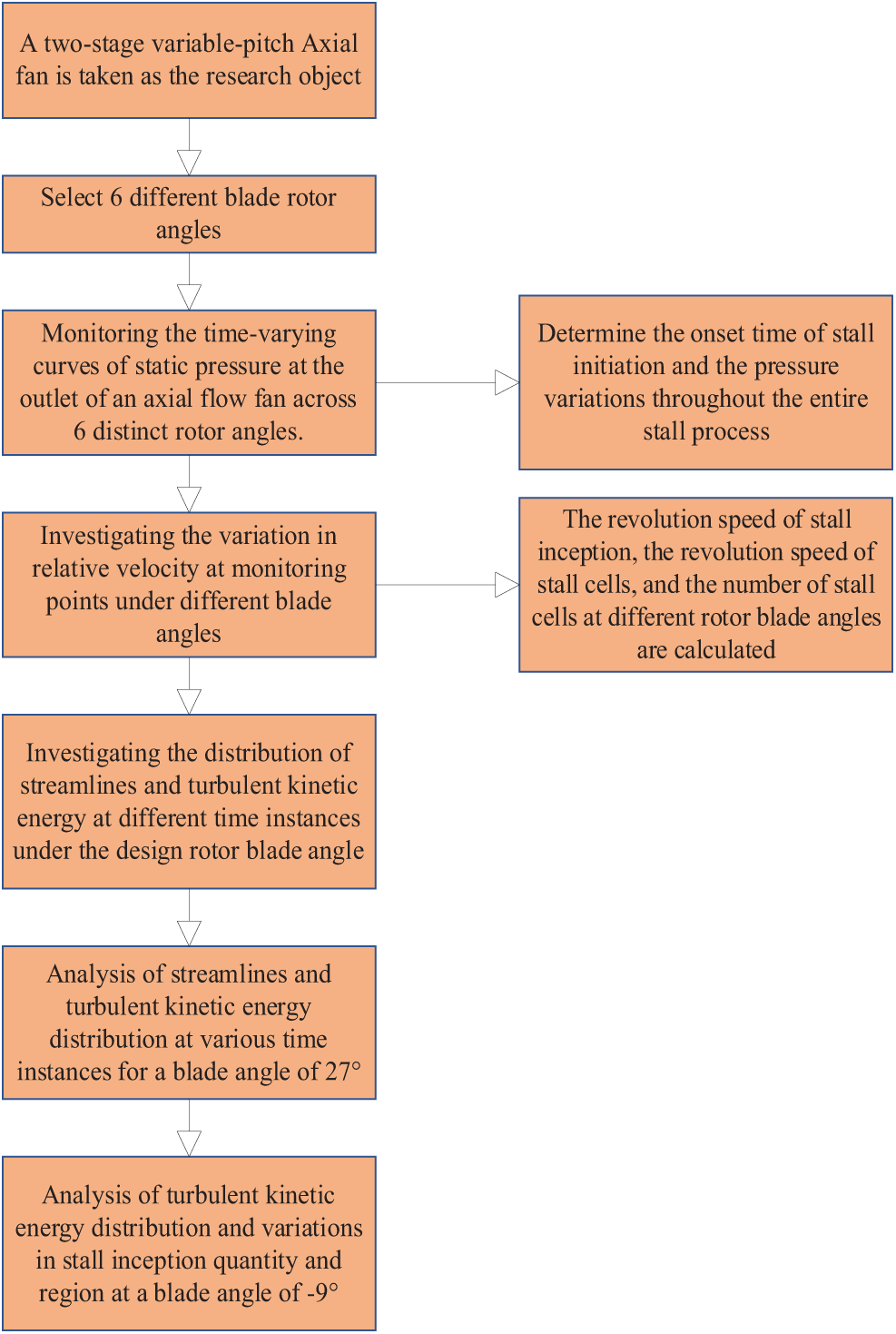
Figure 3: Flow chart of rotor blade angle influence mechanism
3.1 Governing Equations and Turbulence Equation
To ensure the precision of numerical simulation resources for axial fans, it is essential to simplify the computational conditions to a manageable level. The flow field within axial fans is modeled as three-dimensional, incompressible, and unsteady. As stated in the literature, variations in gas density, viscosity, and temperature can be disregarded. Consequently, the energy equation is omitted from consideration [42]. In this study, the numerical simulations employ the Reynolds-Averaged Navier-Stokes (RANS) equations, detailed as follows:
Continuity equation:
Motion equation (Reynolds equation):
where
The flow dynamics are analyzed using the Unsteady Reynolds Averaged Navier-Stokes (URANS) equations, which are coupled with the Realizable
Each rotor impeller of the axial fan comprises 24 twisted blades, featuring a blade thickness that progressively increases from the tip towards the hub. The intricate geometry of the fan poses challenges, such as generating a large number of cells with acceptable skewness. Furthermore, the equations governing the moving zone exhibit difficulties, where unstructured grids demonstrate superior convergence and skewness properties compared to structured grids. Consequently, the meshing strategy adopted leverages multi-block grid technology. Unstructured grids are found to be more suitable for both the rotor and stator, while hexahedral unstructured grids are established for other components. To ensure precision, boundary layer grids are employed on the blade surface, maintaining a wall-to-first-layer grid node distance within the range of y+ < 5. To enhance calculation accuracy, a size function is utilized to refine the grid in critical areas like the blade edge and tip clearance. Partial grid configurations of the axial fan are depicted in Fig. 4.
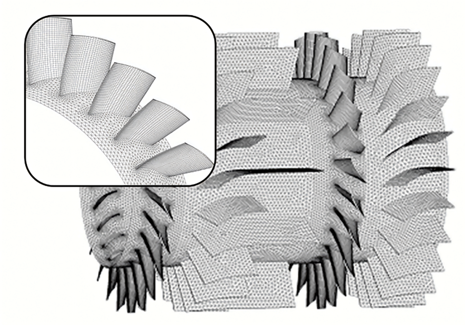
Figure 4: The partial view of the mesh for the axial fan
In this study, grid independence verification is conducted to minimize the influence of grid count on simulation outcomes. The selected mesh sizes for the geometric model are 3.75 × 10⁶, 5.87 × 10⁶, 6.94 × 10⁶, and 7.85 × 10⁶. A comparison of steady-state simulation results across these grid sizes with experimental data is presented in Fig. 5. It is observed that the impact on simulation results becomes negligible when the grid count reaches 5.87 × 10⁶. Furthermore, the relative errors in total pressure, ranging from 1.523% to 5.245% in different steady-state simulation cases, align with experimental findings, confirming the suitability of the established model for simulation purposes.
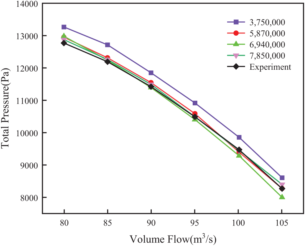
Figure 5: Total pressure vs. Volume flow curves
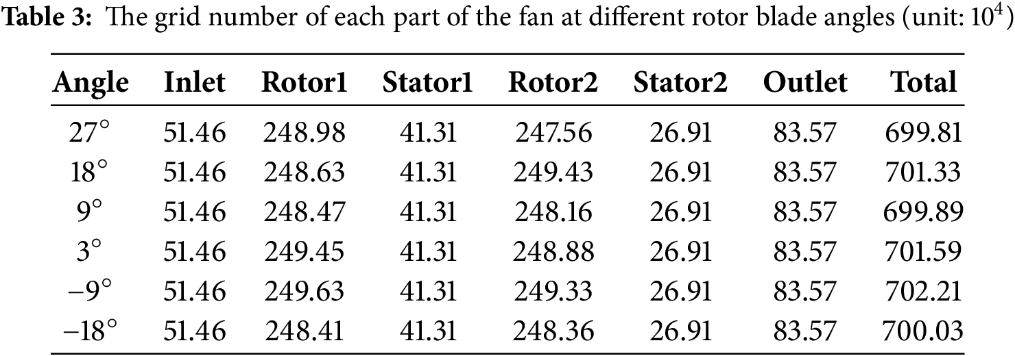
To ensure the independence of the number of grids, the consistency of grids of each part of the fan is used in different angles. The specific data are shown in Table 3.
Computational Fluid Dynamics (CFD) software Fluent is employed to perform three-dimensional numerical simulations of fan systems, yielding valuable insights into the internal flow characteristics within the fan. Within the realm of CFD research and applications, Fluent occupies a pivotal position as a comprehensive and highly integrated software tool. Its powerful solver forms the core of Fluent, which, when combined with its flexible pre- and post-processing capabilities, offers researchers a holistic solution encompassing geometric modeling, mesh generation, boundary condition specification, physical model selection, and result visualization [43,44]. For the purpose of numerical simulation, the collector inlet and outlet diffuser are designated as the inlet and outlet of the computational domain, respectively. A pressure inlet boundary condition is selected, with the total pressure set at 1 atmosphere. Conversely, a pressure outlet boundary condition is adopted for the outlet. During steady-state calculations, the rotating regions of the two rotors are modeled using a Multiple Reference Frame (MRF) approach, rotating at a speed of 1490 revolutions per minute. The fan domains are interconnected via interface boundary conditions, while no-slip wall boundary conditions are imposed on all remaining parts of the fan. In the context of unsteady-state calculations, the research utilizes a moving mesh technique to capture the transient flow behavior [45–47].
In order to simulate the complete stall process, the throttle condition is applied at the exit to determine the static pressure Psout.
where Piin is the environment atmospheric pressure, k0 is a constant, k1 is the valve opening, ρ is the air density and U is the outlet axial flow velocity. The operating condition of the ventilation system is determined by the intersection of the fan performance curve and valve throttling line. The throttle condition can automatically simulate a rotating stall without any intervention to change the back pressure.
4.1 Time-Domain Characteristics of Outlet Static Pressure of Axial Fan
The inception of stall within the fan and the subsequent pressure variations throughout the stall process can be precisely determined by monitoring the static pressure at the axial fan outlet. Fig. 6 presents the temporal variation curves of the outlet static pressure for six distinct rotor angles. The specific valve opening denoted as ks signifies the point at which stall inception occurs. Inspection of the figure reveals that, at a valve opening of ks+0.001, the static pressure at the outlet of the axial fan for all six rotor angles stabilizes promptly and remains constant at 1.3196 × 10⁴ Pa, 1.327 × 10⁴ Pa, 0.8681 × 10⁴ Pa, respectively. As the valve opening decreases further, a notable reduction in axial fan flow is observed across all rotor angles. Under these conditions, the outlet static pressure stabilizes at 1.2515 × 10⁴ Pa, 1.085 × 10⁴ Pa, 0.7750 × 10⁴ Pa, respectively. These observations indicate that, as the rotor blade angle varies between 27° and −18°, the static pressure in each state decreases sequentially. This finding aligns with the pressure variation patterns observed in the surge curve of the fan’s original sample.
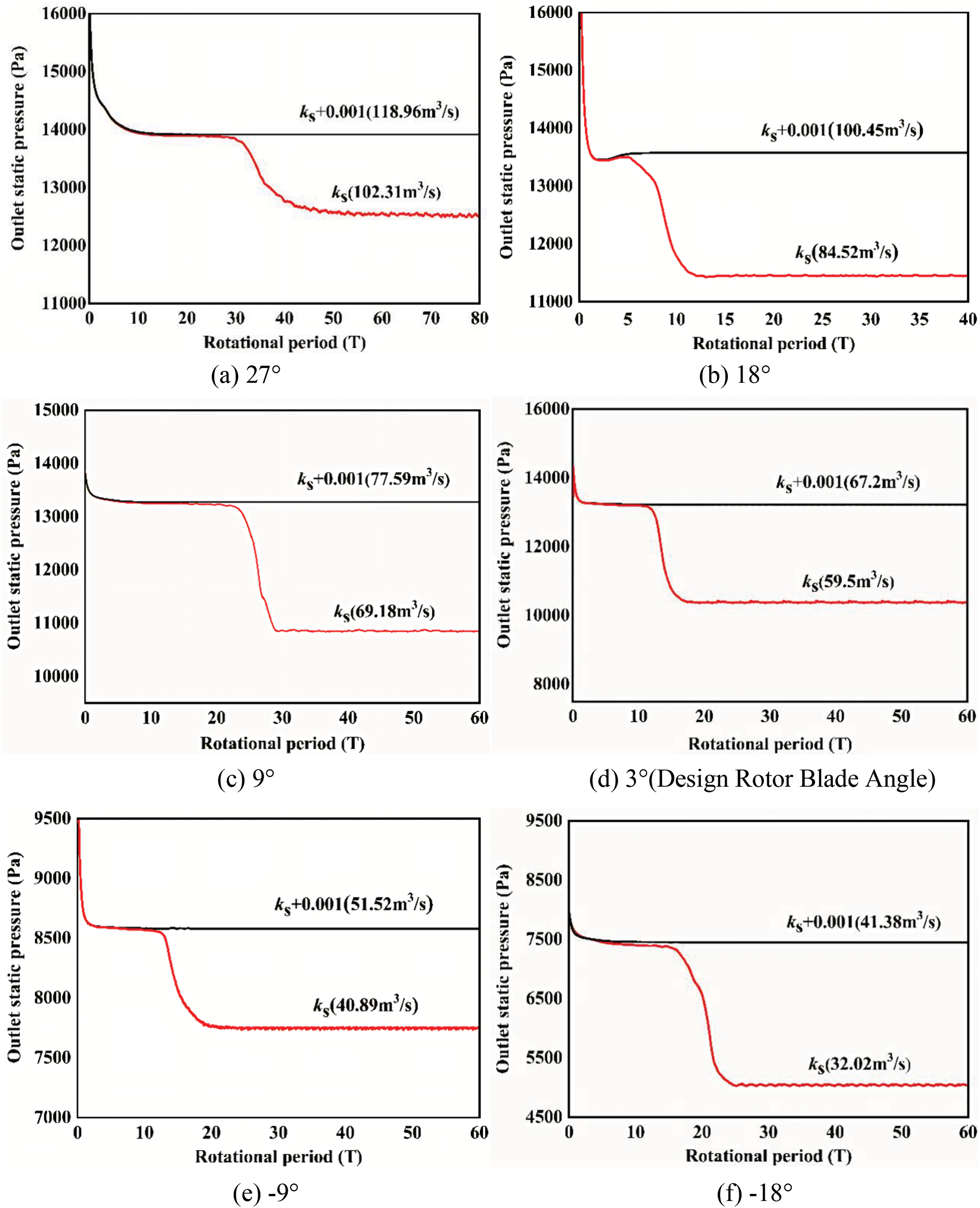
Figure 6: The variation curve of axial fan outlet static pressure with time under different rotor blade angles
At the valve opening corresponding to ks, the axial fan transitions from a stable operational state to the onset of stall, ultimately progressing into a rotating stall. Consequently, the outlet static pressure exhibits periodic fluctuations, which are in accordance with the pressure variations observed at the axial fan outlet during the occurrence of rotating stall. A comparison of the static pressure variation curves depicted in Fig. 6 for six different rotor blade angles at ks reveals that, at a rotor blade angle of 27°, the fan’s static pressure evolves from one stable state to another through approximately 28 cycles. This duration is notably longer than the 13 cycles required at the other rotor blade angles. Based on these observations, it is inferred that the stall mechanism within the axial fan at a rotor blade angle of 27° may deviate from those prevalent at the other rotor angles. To validate this hypothesis, numerical probes were incorporated into the numerical calculation process.
4.2 The Law of Relative Velocity Variation at Numerical Probe
To analyze variations in relative velocity within the rotating impellers before and after the onset of rotating stall, and to subsequently compute pertinent characteristics of stall inception and stall cells, a total of 12 numerical probes were positioned in both the first and second rotating impellers of the fan. Specifically, three numerical probes were placed at 50% and 90% of the radial blade heights within the internal flow channel of Rotor 1, spaced at intervals along the circumference of three channels, and labeled as m1-1, m1-2, m1-3, h1-1, h1-2, and h1-3, respectively. A similar naming convention was adopted for Rotor 2, with probes designated as m2-1, m2-2, m2-3, h2-1, h2-2, and h2-3. The exact location of each numerical probe in the first stage is illustrated in Fig. 7.
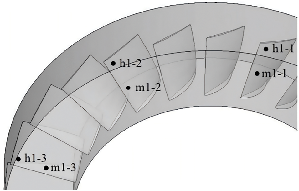
Figure 7: Numerical probe arrangement scheme
Fig. 8 depicts the curves of relative velocity variations observed at monitoring points in Rotor 1 and Rotor 2, across rotor blade angles of 27°, 9°, 3°, and −9°. Analysis of the time-domain characteristics presented in Fig. 8 reveals notable differences in amplitude and frequency at the rotor blade angle of 27°, compared to the other conditions. Specifically, as illustrated in Fig. 8-I(a), stall inception initially manifests at 22.6T in Rotor 2, subsequently leading to an unstable flow in Rotor 1. Approximately 17 rotor periods later, both Rotor 1 and Rotor 2 transition from stall inception to a fully developed stall state nearly simultaneously, with the variation in relative velocity exhibiting a characteristic modal wave pattern. In Fig. 8-I(b) through 8-Ⅰ(d), the progression from stall inception to a complete stall state is similarly observed in both Rotor 1 and Rotor 2. However, it becomes evident that the stall characteristics differ from a modal wave, instead presenting as spikes.
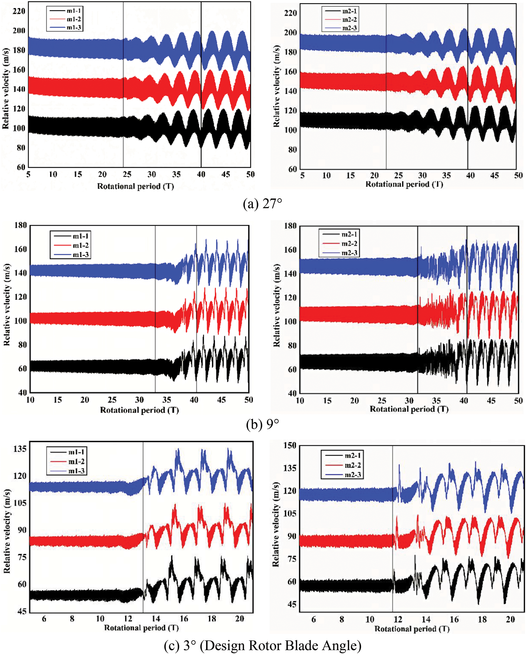
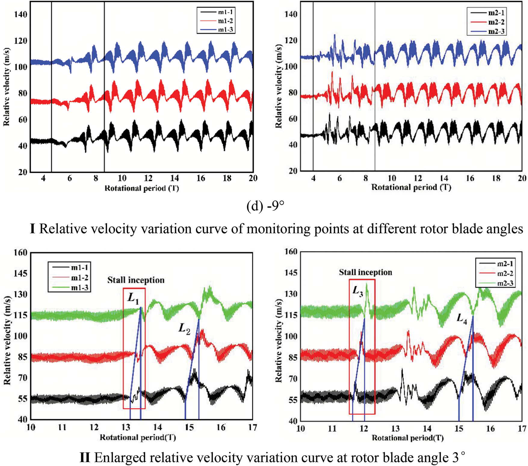
Figure 8: Variation curves of relative velocity at different monitoring points for Rotor 1 and Rotor 2
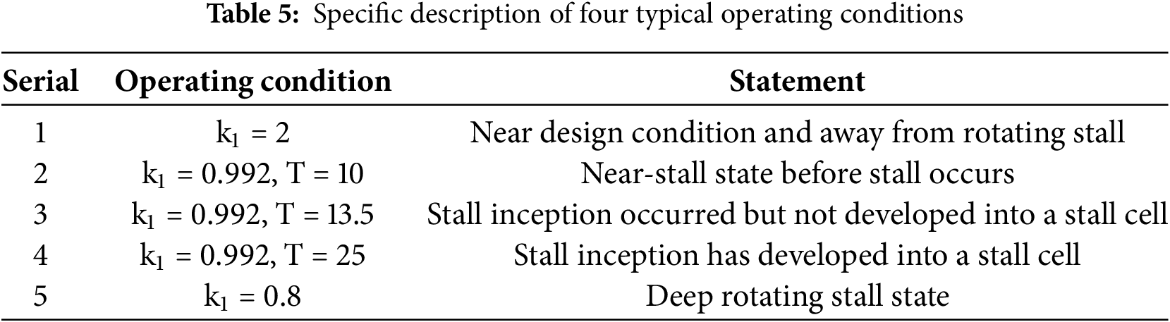
To gain further insight into the characteristics of stall inception in an axial fan at various rotor blade angles, the rotational speeds associated with stall inception and stall cells, as well as the number of stall cells at different rotor blade angles, are computed. Using the design rotor blade angle of 3° as an illustrative example, the specific methodologies employed for these calculations are outlined as follows:
As shown in Fig. 8-II, L1 is located in the range between 12 to 14 T and the distance of the monitoring point m1-1 and m1-3 is 0.333 T, thus the stall inception revolution speed is calculated from:
In the range of 15 to 17 T, the distance between the monitoring point m1-1 and m1-3 is 0.458 T, thus the revolution speed of the stall cell can be calculated as:
The period of the stall group shown in Fig. 8-II is about 1.833 T, thus the number of the stall cell is:
where ws represents the rotational speed of the stall inception, wr represents the revolution speed of the stall cells, and Nc represents the number of the stall cells.
The aforementioned method can be applied to determine ws, wr, Ns, and Nc for the remaining five rotor angles, with the specific findings summarized in Table 4. A comparative analysis of the modal wave and spike stall inception characteristics across different rotor blade angles reveals that the stall inception pattern at 27° exhibits modal wave behavior, whereas the other angles demonstrate spike behavior. Notably, the values of the five characteristic parameters at 18°, 9°, and 3° are comparable. Conversely, at rotor angles of −9° and −18°, a single stall cell is observed, with stall inception varying throughout the evolution process. To elucidate the impact of the differing stall inception types and the variation in the number of inceptions during rotating stall, the flow fields during the stall evolution at rotor blade angles of 3°, 27°, and −9° are selected for further investigation below.
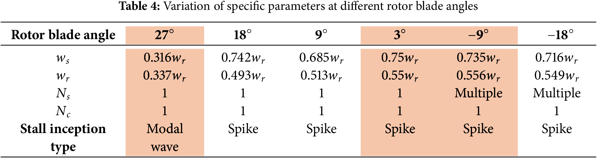
4.3 The Flow Field Variation Law under the Design Rotor Blade Angle
Fig. 9 showcases the streamline patterns and turbulent kinetic energy distributions for Rotor 2 at five representative time points, both preceding and subsequent to the onset of stall, featuring a rotor blade angle of 3° as per its design specifications. The precise operational parameters under consideration are outlined in Table 5 and correspond to scenarios designated as (a) within the broader context outlined by (e) in Fig. 9.
Figure 9: Distribution of streamlines and turbulent kinetic energy at various typical moments before and after stall in the mid-section of an impeller with a rotor blade angle of 3°
In Condition 1, under conditions nearing the design specification, the flow within the impeller exhibits a relatively homogeneous characteristic. The streamline distribution indicates an insignificant presence of relative velocity components along the blade’s radial height. However, analysis of the turbulence kinetic energy distribution reveals a slight disturbance at the blade suction side, particularly near the blade tip, attributed to the presence of an axial vortex. Transitioning to Condition 2, although the velocity at the pressure surface remains relatively low, the influence of tip clearance becomes prominent, resulting in more evident disturbances at the blade tip. The distribution pattern of turbulence kinetic energy highlights a region of elevated turbulence kinetic energy spanning from 90% of the blade height to the tip, with a more pronounced manifestation adjacent to the suction side. This observation is attributed to the augmentation of turbulence pulsations stemming from the expansion of the tip separation vortex region.
Condition 3 exhibits a streamline distribution characterized by distinct flow separation and the emergence of recirculation zones in proximity to the blade tip, spanning approximately eight flow channels. Notably, a fully developed recirculation vortex is observed in the mid-section of the flow passage, encompassing 80% of the blade’s height up to its tip. Within this region, the fluid’s relative velocity is minimal, approaching stagnation conditions. The backflow pattern is directed from the blade’s suction surface towards the pressure surface, subsequently returning to the suction surface. The flow separation phenomena induce a high turbulence kinetic energy zone, which expands considerably, occupying 70% of the blade height up to the tip. This zone experiences a substantial increase in turbulence kinetic energy values, influenced by the onset of stall. In comparison to the impeller’s rotational direction, the stall inception rotates clockwise in the circumferential plane, leading to a progressive deterioration of the co-directional flow channels in its vicinity. Conversely, adjacent reverse flow channels, influenced by an increase in flow rate and a decrease in the angle of attack, exhibit improvements relative to Condition 1. These modifications are attributed to the altered flow dynamics. Meanwhile, the flow characteristics within the remaining channels remain uniform and unaffected by the aforementioned phenomena.
After approximately 25 cycles, Condition 4 exhibits the evolution of stall inception into a fully developed stall cell, rotating at a stable speed in a clockwise direction relative to the impeller. This development further exacerbates the flow field within the impeller, resulting in a more uneven circumferential distribution. Notably, approximately 11 consecutive flow channels experience significant disturbance, with eight of these channels forming a prominent recirculation region that spans 50% of the blade height up to its tip. The high turbulence kinetic energy within the core of the stall cell expands almost entirely across the flow channel, significantly enhancing the disturbance levels in other regions within the stall cell. In contrast, the flow field in the adjacent channel located in the counterclockwise direction relative to the stall cell undergoes improvement, gradually diverging from stall conditions.
In Condition 5, a reduction in flow rate leads to the axial fan entering a profound rotating stall state. The streamline and turbulence kinetic energy distributions mirror those observed in Condition 4; however, the affected region exhibits a broader scope. Consequently, the number of flow channels impacted by the stall cell increases to 13, indicating a more extensive disturbance across the fan’s flow field.
4.4 Comparation between Spike and Modal Wave Stall Inception Pattern
The preceding analysis reveals that modal wave stall initiates at a rotor blade angle of 27°. To investigate the implications of modal wave stall inception on the internal flow dynamics of the axial fan, four representative conditions during the stall progression are selected for examination of transient streamline patterns and turbulence kinetic energy distributions. These specific conditions are detailed in Table 6 and correspond respectively to panels (a), (b), (c), and (d) of Fig. 10.
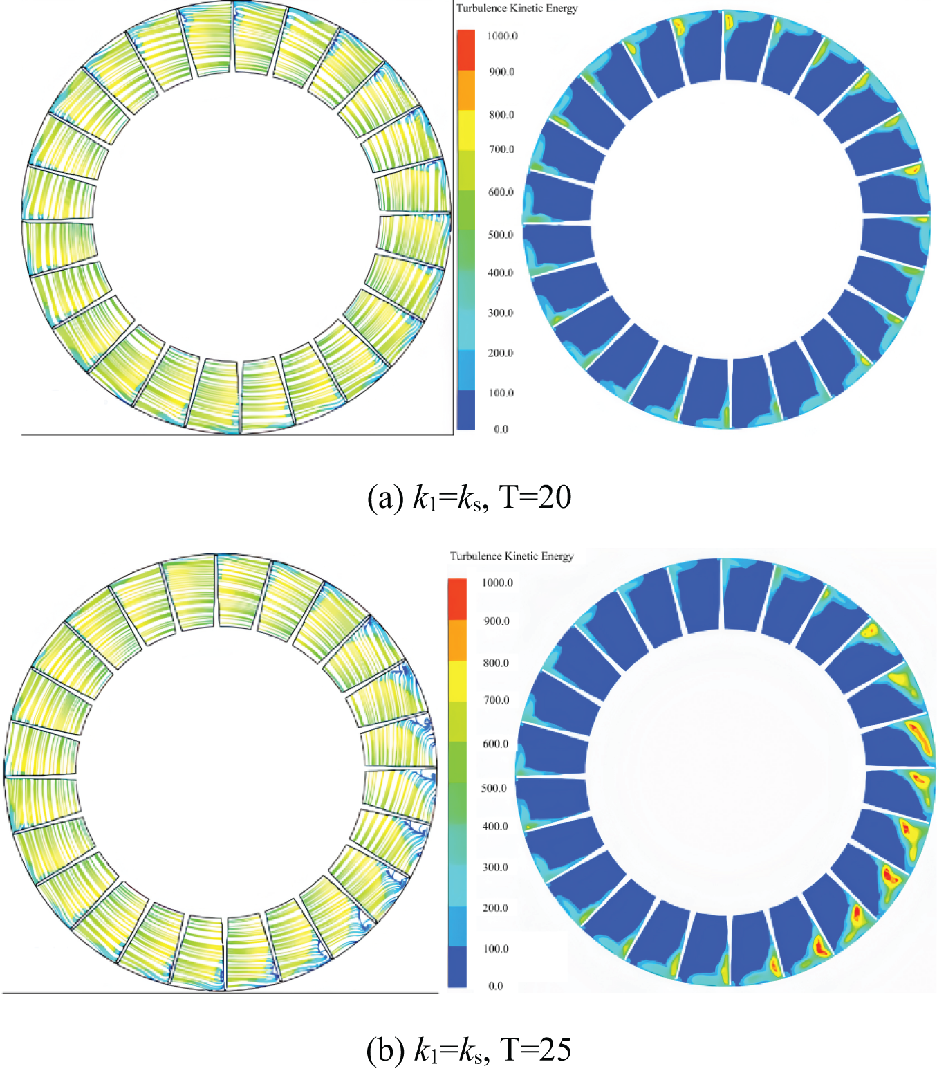
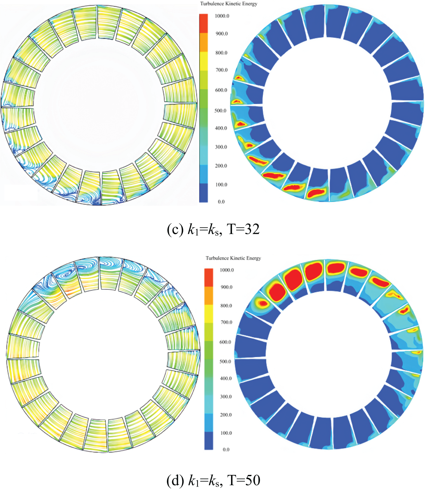
Figure 10: Flow lines and turbulence kinetic energy distribution in the middle section of the impeller at four typical moments before and after stall
In Condition 1, the streamline distribution within the impeller exhibits circumferential uniformity. Additionally, an “L”-shaped backflow and flow separation phenomenon is observed in the suction surface area adjacent to the blade tip of each flow channel. The distribution of turbulence kinetic energy displays a comparable range, with high energy levels predominantly concentrated between 70% and 90% of the blade height, proximate to the suction surface.
In Condition 2, the advanced development of the flow field results in notable flow separation and backflow phenomena in proximity to the suction surfaces of seven channels. The flow within these backflow regions becomes nearly stagnant, suggesting the onset of stall inception. A comparison with Fig. 10a reveals that, aside from the channels affected by stall inception, the flow field near the blade tips of the remaining channels experiences some degree of improvement. The distribution of high turbulence kinetic energy aligns with the location of the recirculation zones, indicating a substantial increase in turbulent fluctuation intensity within the corresponding blade tip regions of the flow channels. The disturbed flow field evolves in two directions: one extending from the suction to the pressure side along the flow channel near the blade tip, and the other progressing along the suction surface from the blade tip towards the root.
In Condition 3, the recirculation region influenced by stall inception expands in a clockwise direction compared to Condition 2. The recirculation vortex is most pronounced in the initial few channels, encompassing the entire area from the blade tip down to 80% of the blade height. The region of high turbulence kinetic energy experiences further development, extending both radially and circumferentially from the suction surface near the blade tip, with a notable increase in its magnitude. Analogous to Condition 2, the disturbed flow field tends to intensify in several channels positioned clockwise and away from the inception region, while it diminishes in those closer to it.
After 50 cycles of evolution, the flow field state is depicted in Fig. 10d. The stall inception has matured into a full stall cell, leading to a more pronounced circumferential non-uniformity within the impeller flow field. This stall cell encompasses approximately 10 impeller flow passages, with significant recirculation occurring in six consecutive channels. The flow separation vortex spans roughly 50% of the blade height. The distribution of turbulence kinetic energy mirrors that of the recirculation region, with a notable enhancement in turbulent fluctuation intensity within the affected channels. Consequently, the flow field experiences severe disturbance, with the high turbulence kinetic energy region nearly encompassing the entire channel. The presence of the stall cell significantly degrades the flow field, while the performance of the other channels improves correspondingly.
In summary, stall inception in the axial fan with a 27° rotor blade angle initiates proximity to the suction surface of the blade. As the flow field evolves, the stall inception progressively develops in two directions: circumferentially from the suction surface towards the pressure surface, and radially from the blade tip towards the root. Following approximately 18 revolutions (T) of evolution, a mature stall cell encompassing 10 channels emerges and rotates stably with the impeller. Subsequent to the stall inception, the flow field undergoes an evolution spanning approximately 18 cycles, culminating in the formation of a stable stall cell occupying 10 channels that rotates in unison with the impeller.
A comparison between the spike stall and modal wave stall inception patterns reveals notable differences in the initial disturbance positions within Condition 1. Specifically, the recirculation zones and regions of high turbulence kinetic energy associated with the spike stall are distributed in an “L”-shaped configuration along the suction surface proximal to the blade tip. Conversely, the flow field in the case of the modal wave stall maintains a more homogeneous gradient distribution in the radial direction. Furthermore, upon the onset of stall inception, the flow field disturbance in the spike stall exhibits a broader range and a higher degree of perturbation. This characteristic is a hallmark of the spike stall, wherein as the stall inception evolves into a stall cell, the scale gradually expands over a relatively brief period.
4.5 The Flow Field Variation Law of Multiple Stall Inceptions
Fig. 11 illustrates the distribution of turbulence kinetic energy at 90% of the radial blade height for four representative conditions, both prior to and subsequent to the onset of rotating stall in Rotor 2. The eight distinct time points depicted in the figures comprehensively demonstrate the evolution of the number and location of stall inception events throughout the process.
Figure 11: The turbulence kinetic energy distribution at 90% cross section of impeller at 9 different time during inceptions evolution to a stall cell
Fig. 11a depicts a near-stall condition, wherein the turbulence intensity across each flow channel of the impeller is minimal, resulting in a circumferentially uniform flow field distribution. After 4.2 revolutions, corresponding to Fig. 11b, a prominent region of high turbulence kinetic energy becomes evident at the inlet of a channel near the leading edge of the pressure surface. Additionally, this disturbance extends to the outlet of the adjacent channel, spanning approximately half of the chord length. Based on these observations, the onset of stall inception is inferred.
Observing Fig. 11c, it is evident that the region of high turbulence kinetic energy continues to propagate towards the inlet and adjacent channels, resulting in the emergence of two stall inceptions within the flow field, each encompassing two channels. Notably, the turbulence kinetic energy in channels distant from these stall inceptions decreases, suggesting an improvement in the flow field. As the flow field further evolves, Fig. 11d reveals an increase in the number of stall inceptions to three. These inception regions, exhibiting similar disturbance intensities, expand axially on both sides, with a small region of high turbulence kinetic energy located between them. Under these conditions, the flow field’s unevenness becomes more pronounced. At 6.5 T, as depicted in Fig. 11e, the number of stall inceptions in the impeller increases to four. Among them, three stall inceptions each span two channels with a one-channel interval, while the remaining, larger stall inception occupies approximately three flow channels and exhibits a relatively high turbulence kinetic energy value.
As illustrated in Fig. 11f, the degradation of the flow field within the channel results in significant blockage, under which the expansion of stall inceptions along both axial and radial directions becomes more evident. Although the number of stall inceptions remains constant, the largest inception spans approximately four impeller channels, nearly occupying the entire axial flow channel from inlet to outlet. Starting from 7.5 T, adjacent stall inceptions begin to interact and merge into larger entities. The largest stall inception region has expanded to encompass seven channels, while the remaining two stall inceptions, of equivalent size, occupy about three channels each. As depicted in Fig. 11h, the stall inceptions continue to interact and consolidate, forming a substantial disturbance region that spans ten channels. Additionally, a small area of high turbulence kinetic energy is observed away from this large disturbance region.
As depicted in Fig. 11i, following 10 cycles, the region of high turbulent energy occupies nearly the entire channel in the midst of several passages, with only one stall cell encompassing 10 channels within the impeller. Under these circumstances, the axial fan experiences complete stall conditions. A comparison with Fig. 11a reveals that an improvement in the flow field is evident, as the high turbulence kinetic energy region diminishes due to the increased flow rate and decreased attack angle in the flow channel opposite to the stall cell’s movement.
The analysis presented above suggests that, at a rotor blade angle of −9°, the initiation of stall commences at the inlet of the blade’s leading edge, in proximity to the pressure side. As the flow field evolves, the number of stall inceptions undergoes variation. At its peak, four stall inceptions are observed within the impeller. With continued evolution of the flow field, the scope of these stall inceptions expands bilaterally along the axial direction, extending from the inlet of the flow channel to adjacent channels. Multiple stall inceptions gradually interact and coalesce, leading to a decrease in their number and a rapid increase in the size of individual stall inception regions. Ultimately, a mature stall cell, encompassing 10 channels, rotates stably in the impeller, moving in the reverse direction.
This paper integrates numerical simulation results to elucidate the mechanism by which stall inception influences the evolution process within a two-stage variable-pitch axial fan. The key findings are summarized as follows:
1. The time-domain analysis of static pressure at the outlet of the axial fan, for varying rotor blade angles, reveals distinct stall inception patterns. Specifically, a modal wave stall inception pattern is observed at a rotor blade angle of 27°, whereas spike patterns are noted at the other angles. Among the five rotor blade angles examined, multiple stall inceptions are evident at −9° and −18°.
2. In the case of spike stall inception, the flow field maintains a relatively uniform gradient distribution in the radial direction. Following the onset of stall inception, the disturbance region within the flow field undergoes rapid expansion within a short period. Conversely, modal wave stall inception initiates from the blade tip in proximity to the suction side, exhibiting “L”-shaped characteristics. This stall inception progresses gradually, extending along both the blade tip and suction side directions during the stall development.
3. In the flow field characterized by multiple stall inceptions, the stall inception originates from the leading edge of the blade inlet, in close vicinity to the pressure side. Throughout the evolution process, the number and area of these inceptions undergo variation. As the flow field further evolves, the scope of stall inceptions expands bilaterally along both the axial and radial directions. Multiple stall inceptions interact and merge with each other, ultimately culminating in the fusion of all stall inceptions into a single, larger stall.
Acknowledgement: The authors acknowledge the reviewers for providing valuable comments and helpful suggestions to enhance the manuscript.
Funding Statement: This research was funded by the Natural Science Foundation of Hebei Province, China (Grant No. E2022502052), Fundamental Research Funds for the Central Universities, China (Grant No. 2022MS081), and Fundamental Research Funds for the Central Universities, China (Grant No. 2023MS121).
Author Contributions: The paper was conceptualized by Yongsheng Wang and methodologically developed by Yongsheng Wang and Xiangwu Lu. The first draft was written by Yongsheng Wang and Xiangwu Lu, while supervision and visualization were done by Lei Zhang and Wei Yuan. All authors reviewed the results and approved the final version of the manuscript.
Availability of Data and Materials: The data that support the findings of this study are available from the corresponding author, Wei Yuan, upon reasonable request.
Ethics Approval: Not applicable.
Conflicts of Interest: The authors declare no conflicts of interest to report regarding the present study.
Nomenclature
| M-G | Moore and Greitzer |
| MRF | Multiple coordinate reference frame |
| CFD | Computational Fluid Dynamics |
| n | Rated speed |
| Nr | Number of moving blade |
| D1 | Inlet diameter |
| D2 | Outlet diameter |
| D | Rotor diameter |
| qv* | Design flow rate |
| P | Motor rated power |
| Reynolds average velocity of i | |
| Reynolds average velocity of j | |
| Pulsating speed in the direction of i | |
| Pulsating speed in the direction of j | |
| Density | |
| t | Time |
| Total stress tensor | |
| Psout | Static pressure |
| Piin | Environment atmospheric pressure |
| k0 | Constant |
| k1 | Valve opening |
| U | Outlet axial flow velocity |
| ws | Rotational speed of the stall inception |
| wr | Revolution speed of the stall cells |
| Nc | The number of the stall cells |
| Coefficient of kinematic viscosity |
References
1. Zhang L, He R, Wang X, Zhang Q, Wang S. Study on static and dynamic characteristics of an axial fan with abnormal blade under rotating stall conditions. Energy. 2019;170:305–25. doi:10.1016/j.energy.2018.12.125. [Google Scholar] [CrossRef]
2. An G, Kang J, Zou Y, Zhang L, Lang J, Yuan W, et al. Investigation of the unsteady flow in a transonic axial compressor adopted in the compressed air energy storage system. J Energy Storage. 2023;63:106928. doi:10.1016/j.est.2023.106928. [Google Scholar] [CrossRef]
3. Emmons HW, Pearson CE, Grant HP. Compressor surge and stall propagation. J Fluids Eng. 1955;77(4):455–67. doi:10.1115/1.4014389. [Google Scholar] [CrossRef]
4. Greitzer EM. Surge and rotating stall in axial flow compressors: part I: theoretical compression system model. J Eng Power. 1976;98(2):190–8. doi:10.1115/1.3446138. [Google Scholar] [CrossRef]
5. Dazin A, Cavazzini G, Pavesi G, Dupont P, Coudert S, Ardizzon G, et al. High-speed stereoscopic PIV study of rotating instabilities in a radial vaneless diffuser. Exp Fluids. 2011;51(1):83–93. doi:10.1007/s00348-010-1030-x. [Google Scholar] [CrossRef]
6. Sun X, Meng D, Liu B, Wang Q. Numerical investigation of differential speed operation of two impellers of contra-rotating axial-flow fan. Adv Mech Eng. 2017;9(10):168781401772008. doi:10.1177/1687814017720083. [Google Scholar] [CrossRef]
7. Hu C, Yang C, Shi X, Zou R, Liu L, Chen H. Investigation of rotating stall in radial vaneless diffusers with asymmetric inflow. Aerosp Sci Technol. 2020;96:105546. doi:10.1016/j.ast.2019.105546. [Google Scholar] [CrossRef]
8. Ohta Y, Fujita Y, Morita D. Unsteady behavior of surge and rotating stall in an axial flow compressor. J Therm Sci. 2012;21(4):302–10. doi:10.1007/s11630-012-0548-z. [Google Scholar] [CrossRef]
9. Sakata Y, Ando S, Fujisawa N, Ohta Y. Development of rotating stall cell under coexisting phenomena of surge and rotating stall in an axial-flow compressor. In: 8th Joint Fluids Engineering Conference; 2019 Jul 28–Aug 1; San Francisco, CA, USA: ASME-JSME-KSME. doi: 10.1115/AJKFluids2019-5310. [Google Scholar] [CrossRef]
10. Zhang L, Zhang L, Zhang Q, Jiang K, Tie Y, Wang S. Effects of the second-stage of rotor with single abnormal blade angle on rotating stall of a two-stage variable pitch axial fan. Energies. 2018;11(12):3293. doi:10.3390/en11123293. [Google Scholar] [CrossRef]
11. Ye X, Hu J, Zheng N, Li C. Numerical study on aerodynamic performance and noise of wind turbine airfoils with serrated gurney flap. Energy. 2023;262:125574. doi:10.1016/j.energy.2022.125574. [Google Scholar] [CrossRef]
12. Ye X, Zheng N, Hu J, Li C, Xue Z. Numerical investigation of the benefits of serrated Gurney flaps on an axial flow fan. Energy. 2022;252:124072. doi:10.1016/j.energy.2022.124072. [Google Scholar] [CrossRef]
13. Pullan G, Young AM, Day IJ, Greitzer EM, Spakovszky ZS. Origins and structure of spike-type rotating stall. J Turbomach. 2015;137(5):051007. doi:10.1115/1.4028494. [Google Scholar] [CrossRef]
14. Dodds J, Vahdati M. Rotating stall observations in a high speed compressor: part I: experimental study. J Turbomach. 2015;137(5):051002. doi:10.1115/1.4028557. [Google Scholar] [CrossRef]
15. Hewkin-Smith M, Pullan G, Grimshaw SD, Greitzer EM, Spakovszky ZS. The role of tip leakage flow in spike-type rotating stall inception. J Turbomach. 2019;141(6):061010. doi:10.1115/1.4042250. [Google Scholar] [CrossRef]
16. Choi M, Vahdati M, Imregun M. Effects of fan speed on rotating stall inception and recovery. J Turbomach. 2011;133(4):041013. doi:10.1115/1.4003243. [Google Scholar] [CrossRef]
17. Choi M, Smith NHS, Vahdati M. Validation of numerical simulation for rotating stall in a transonic fan. J Turbomach. 2013;135(2):021004. doi:10.1115/1.4006641. [Google Scholar] [CrossRef]
18. Kim S, Pullan G, Hall CA, Grewe RP, Wilson MJ, Gunn E. Stall inception in low-pressure ratio fans. J Turbomach. 2019;141(7):071005. doi:10.1115/1.4042731. [Google Scholar] [CrossRef]
19. McDougall NM, Cumpsty NA, Hynes TP. Stall inception in axial compressors. In: ASME 1989 International Gas Turbine and Aeroengine Congress and Exposition; 1989 Jun 4–8; Toronto, ON, Canada: American Society of Mechanical Engineers. doi. 10.1115/89-gt-63. [Google Scholar] [CrossRef]
20. Day IJ. Stall inception in axial flow compressors. In: ASME 1991 International Gas Turbine and Aeroengine Congress and Exposition; 1991 Jun 3–6; Orlando, FL, USA: American Society of Mechanical Engineers. doi: 10.1115/91-gt-086. [Google Scholar] [CrossRef]
21. Day IJ, Breuer T, Escuret J, Cherrett M, Wilson A. Stall inception and the prospects for active control in four high speed compressors. In: ASME 1997 International Gas Turbine and Aeroengine Congress and Exhibition; 1997 Jun 2–5; Orlando, FL, USA. doi: 10.1115/97-GT-281. [Google Scholar] [CrossRef]
22. Khaleghi H. Stall inception and control in a transonic fan, part A: rotating stall inception. Aerosp Sci Technol. 2015;41:250–8. doi:10.1016/j.ast.2014.12.004. [Google Scholar] [CrossRef]
23. Inoue M, Kuroumaru M, Tanino T, Furukawa M. Propagation of multiple short-length-scale stall cells in an axial compressor rotor. J Turbomach. 2000;122(1):45–54. doi:10.1115/1.555426. [Google Scholar] [CrossRef]
24. Zhang L, Kang J, Lang J, An G, Zhang Q, Wang L, et al. Stall evolution mechanism of a centrifugal compressor with a wide-long vaneless diffuser. J Therm Sci. 2024;33(3):899–913. doi:10.1007/s11630-024-1951-y. [Google Scholar] [CrossRef]
25. Zhang H, Yu X, Liu B, Wu Y, Li Y. Using wavelets to study spike-type compressor rotating stall inception. Aerosp Sci Technol. 2016;58:467–79. doi:10.1016/j.ast.2016.09.006. [Google Scholar] [CrossRef]
26. An G, Kang J, Wang L, Zhang L, Lang J, Li H. Decoupling and reconstruction analysis in a transonic axial compressor using the dynamic mode decomposition method. Phys Fluids. 2023;35(8):084120. doi:10.1063/5.0160392. [Google Scholar] [CrossRef]
27. Wernet MP, Van Zante D, Strazisar TJ, John WT, Prahst PS. 3-D digital PIV measurements of the tip clearance flow in an axial compressor. In: ASME Turbo Expo 2002: Power for Land, Sea, and Air; 2002 Jun 3–6; Amsterdam, The Netherlands. p. 1167–79. doi:10.1115/gt2002-30643. [Google Scholar] [CrossRef]
28. Vo HD, Tan CS, Greitzer EM. Criteria for spike initiated rotating stall. In: ASME Turbo Expo 2005: Power for Land, Sea, and Air; 2005 Jun 6–9; Reno, NV, USA. p. 155–65. doi:10.1115/gt2005-68374. [Google Scholar] [CrossRef]
29. Schlechtriem S, Lötzerich M. Breakdown of tip leakage vortices in compressors at flow conditions close to stall. In: ASME International Gas Turbine & Aeroengine Congress & Exhibition; 1997 Jun 2–5; Orlando, FL, USA: American Society of Mechanical Engineers. doi: 10.1115/97-gt-041. [Google Scholar] [CrossRef]
30. Berdanier RA, Smith NR, Young AM, Key NL. Effects of tip clearance on stall inception in a multistage compressor. J Propuls Power. 2018;34(2):308–17. doi:10.2514/1.B36364. [Google Scholar] [CrossRef]
31. Khalid SA, Khalsa AS, Waitz IA, Tan CS, Greitzer EM, Cumpsty NA et al. Endwall blockage in axial compressors. In: ASME 1998 International Gas Turbine and Aeroengine Congress and Exhibition; 1998 Jun 2–5; Stockholm, Sweden: International Gas Turbine Institute. doi: 10.1115/98-gt-188. [Google Scholar] [CrossRef]
32. Cameron JD. Stall inception in a high-speed axial compressor. USA: University of Notre Dame; 2007. [Google Scholar]
33. Du J, Liu Y, Li J, Zhang W, Zhang H, Nie C. Adaptive feedback control of stability in an axial compressor with circumferential inlet distortion. Chin J Aeronaut. 2023;36(5):187–201. doi:10.1016/j.cja.2023.02.005. [Google Scholar] [CrossRef]
34. Xu R, Hu J, Wang X, Jiang C, Li W. Experimental research on inlet steady swirl distortion in an axial compressor with non-uniform tip clearance. J Therm Sci. 2023;32(1):286–96. doi:10.1007/s11630-022-1729-z. [Google Scholar] [CrossRef]
35. Sun D, Li J, Dong X, Xu R, Sun X. Foam-metal casing treatment on an axial flow compressor: stability improvement and noise reduction. J Turbomach. 2022;144(1):011003. doi:10.1115/1.4051782. [Google Scholar] [CrossRef]
36. Sun D, Li J, Xu R, Dong X, Zhao D, Sun X. Effects of the foam metal casing treatment on aerodynamic stability and aerocoustic noise in an axial flow compressor. Aerosp Sci Technol. 2021;115:106793. doi:10.1016/j.ast.2021.106793. [Google Scholar] [CrossRef]
37. Guo Y, Mao X, Gao L, Yu Y. Numerical study on the stability enhancement mechanism of self-recirculating casing treatment in a counter-rotating axial-flow compressor. Eng Appl Comput Fluid Mech. 2022;16(1):1111–30. doi:10.1080/19942060.2022.2072955. [Google Scholar] [CrossRef]
38. Li J, Liu Y, Du J, Zhang H, Nie C. Implementation of stability-enhancement with tip air injection in a multi-stage axial flow compressor. Aerosp Sci Technol. 2021;113:106646. doi:10.1016/j.ast.2021.106646. [Google Scholar] [CrossRef]
39. Leinhos DC, Schmid NR, Fottner L. The influence of transient inlet distortions on the instability inception of a low pressure compressor in a turbofan engine. In: ASME Turbo Expo 2000: Power for Land, Sea, and Air; 2000 May 8–11; Munich, Germany: International Gas Turbine Institute. doi: 10.1115/2000-gt-0505. [Google Scholar] [CrossRef]
40. Levy Y, Pismenny J. The number and speed of stall cells during rotating stall. In: ASME Turbo Expo 2003, Collocated with the 2003 International Joint Power Generation Conference; 2003 Jun 16–19; Atlanta, GA, USA. p. 889–99. doi:10.1115/gt2003-38221. [Google Scholar] [CrossRef]
41. Zhang H, Yang C, Yang D, Wang W, Yang C, Qi M. Investigation on the stall inception circumferential position and stall process behavior in a centrifugal compressor with volute. J Eng Gas Turbines Power. 2019;141(2):021030. doi:10.1115/1.4041108. [Google Scholar] [CrossRef]
42. Kim YI, Yang HM, Lee KY, Choi YS. Numerical investigation on functional limitations of the anti-stall fin for an axial fan: One-factor analyses. Sci Rep. 2022;12(1):15240. doi:10.1038/s41598-022-19530-9. [Google Scholar] [PubMed] [CrossRef]
43. Jiang B, Wang J, Yang X, Wang W, Ding Y. Tonal noise reduction by unevenly spaced blades in a forward-curved-blades centrifugal fan. Appl Acoust. 2019;146:172–83. doi:10.1016/j.apacoust.2018.11.007. [Google Scholar] [CrossRef]
44. Yang X, Jiang B, Wang J, Huang Y, Yang W, Yuan K, et al. Multi-objective optimization of dual-arc blades in a squirrel-cage fan using modified non-dominated sorting genetic algorithm. Proc Inst Mech Eng Part A J Power Energy. 2020;234(8):1053–68. doi:10.1177/0957650919898983. [Google Scholar] [CrossRef]
45. Sun T, Wu X, Mao K, Wang Z, Yang H, Wei Y. Aerodynamic performance and flow optimization of axial fan based on the neural network and genetic algorithm. Proc Inst Mech Eng Part A J Power Energy. 2024;238(7):1129–47. doi:10.1177/09576509241267857. [Google Scholar] [CrossRef]
46. Wang GB, Zhang XR. Enhanced airflow by additional axial fans for produce cooling in a cold room: a numerical study on the trade-off between cooling performance and irreversibility. Int J Refrig. 2021;130:452–65. doi:10.1016/j.ijrefrig.2021.06.030. [Google Scholar] [CrossRef]
47. Zhang L, Feng X, Yuan W, Chen R, Zhang Q, Li H, et al. Multi-objective optimization method for performance prediction loss model of centrifugal compressors. J Therm Sci. 2024. doi:10.1007/s11630-024-2081-2. [Google Scholar] [CrossRef]
Cite This Article
 Copyright © 2025 The Author(s). Published by Tech Science Press.
This work is licensed under a Creative Commons Attribution 4.0 International License , which permits unrestricted use, distribution, and reproduction in any medium, provided the original work is properly cited.
 Downloads
 Citation Tools