
 Submit a Paper
 Propose a Special lssue
 Open Access
ARTICLE

Optimal Design of Intake System for Racing Engine
1 School of Automotive Engineering, Hubei University of Automotive Technology, Shiyan, 442002, China
2 Key Laboratory of Automotive Power Train and Electronics, Hubei University of Automotive Technology, Shiyan, 442002, China
* Corresponding Author: Runze Yang. Email:
Fluid Dynamics & Materials Processing 2025, 21(7), 1737-1751. https://doi.org/10.32604/fdmp.2025.063103
Received 05 January 2025; Accepted 15 May 2025; Issue published 31 July 2025
 View Full Text
 Download PDF
Abstract
The intake system of a racing engine plays a crucial role in determining its performance, particularly in terms of volumetric efficiency, power output, and throttle response. According to Formula Society of Automotive Engineers (FSAE) regulations, the engine intake system must incorporate a 20 mm diameter flow-limiting valve within the intake manifold. This restriction significantly reduces the airflow into the engine, leading to a substantial drop in power output. To mitigate this limitation, the intake system requires a redesign. In this study, theoretical calculations and one-dimensional thermodynamic simulations are employed to determine the optimal parameters for the intake system. A numerical simulation of the intake system’s flow field is then conducted to refine its structure and layout. Finally, experiments are performed on an engine equipped with the optimized intake system, and its feasibility is evaluated based on experimental results. The findings indicate that the maximum engine torque increases from 56.36 to 59.91 N·m, while the maximum power output rises from 59.16 to 63.94 kW. To further enhance performance and adaptability across different competitions, a variable-length intake manifold control system is also designed, improving both power delivery and overall operational stability of the racing car.Keywords
The intake system of a racing engine plays a pivotal role in determining its performance, particularly in terms of volumetric efficiency, power output, and throttle response. According to the rules of the Formula Student China (FSC), stringent requirements—such as the mandatory use of a 20 mm restrictor downstream of the throttle body—impose unique challenges for optimizing airflow dynamics while minimizing pressure losses and ensuring uniform distribution across cylinders [1]. To address these challenges and enhance both charging efficiency and air intake balance, racing teams are adopting a systematic approach that combines computational fluid dynamics (CFD), one-dimensional (1D) engine cycle simulations, and geometric optimization to achieve competitive advantages.
Recent advancements in computational and experimental methodologies have enabled engineers to tackle these constraints with unprecedented precision. For instance, Pogorevc and Kegl [2] utilized gradient-based optimization algorithms coupled with computational fluid dynamics (CFD) to achieve a 5%–8% power increase across the 7500–11500 rpm range in a Honda CBR600 engine. Similarly, Guo et al. [3] redesigned a restrictor valve with a 14° inlet angle and 22° outlet angle, reducing intake unevenness among cylinders to 1.4% and increasing total airflow by 5.5%. These improvements directly translate to enhanced acceleration and drivability in racing scenarios.
Variable intake systems further amplify performance gains. Vaz et al. [4] implemented a variable-length intake manifold on a CBR600RR engine, shifting peak torque to 58.5 Nm at 9000 rpm and increasing power from 74 to 86 HP. Alves et al. [5] proposed a three-stage variable-length intake manifold, optimized via GT-Power simulations and NSGA-II algorithms. Their design increased volumetric efficiency by 15% at 9000 rpm and boosted mid-range brake power by 12%, leveraging Helmholtz resonance through diameter/length adjustments. This approach quantitatively balanced volumetric efficiency across rpm ranges, demonstrating multi-stage intakes mitigate fixed-geometry compromises while enhancing cylinder filling and peak performance. Computational tools like GT-Power and CFD simulations have proven indispensable in such optimizations, enabling precise tuning of parameters such as runner length, plenum volume, and restrictor geometry [6,7].
As demonstrated by Sedlacek and Skovajsa [8], CFD-driven geometric optimization of plenum chambers and resonance pipes can reduce maximum deviations of inter-cylinder mass flow to 2.2% while achieving a 12% reduction in total pressure losses. Fan et al. [9] presented a parametrically optimized supercharging system for FSAE engines by integrating GT-POWER simulations with experimental validation. The optimized system demonstrates enhanced torque delivery across rpm ranges, improved transient response through pressure regulator tuning, and balanced fuel efficiency—providing a systematic framework for mechanical supercharging in Formula Student applications.
In this study, a novel design incorporating a guide vane cascade is proposed to optimize the intake system. The primary objective of this design is to augment the charging efficiency of the intake system while preserving a streamlined structural configuration. Furthermore, given that the majority of contemporary racing teams employ a fixed intake manifold length, thereby restricting the engine’s capacity to attain peak power across a broad spectrum of engine speeds, an additional design scheme for a variable intake manifold is introduced. By dynamically adjusting the intake manifold length, this scheme enhances the aerodynamic performance of the intake system at different engine speeds, thereby facilitating more efficient power generation by the engine.
2.1 Determination of the Volume of the Plenum
To make the air intake of each cylinder more balanced, a plenum is generally added between the intake manifold and the intake manifold to stabilize the fluctuation of the gas in each intake manifold. Based on empirical data from previous racing car development efforts and the development experience of similar engines [10], it is found that when the volume of the plenum is 5 to 6 times the displacement of the engine, the dynamic performance of the engine and the response of the throttle valve are the best. In order to make the assembly of the entire vehicle more compact, the final selection of the volume of the plenum is 3.533 L.
2.2 Determination of Intake Manifold Length
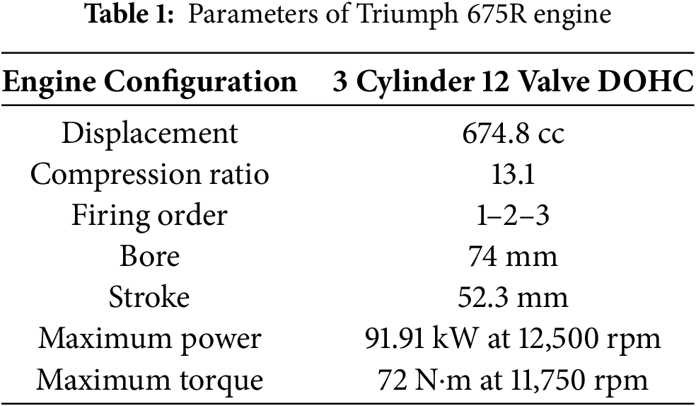
The Triumph 675R engine is a high-speed engine, and its parameters are shown in Table 1. In order to make the peak torque appear earlier and increase the torque in the front and middle-speed range of the engine to adapt to the circuit with lots of short tracks and corners, the optimized engine speed is set at 9000 rpm.
2.3 Dynamic Effects of the Intake System
The dynamic effects that affect the charging efficiency of the intake system mainly include the ram and tuning effects [11].
When the intake valve opens, it creates a negative pressure in the cylinder, drawing air in and simultaneously generating a negative pressure wave that travels to the plenum. This wave reflects back as a positive pressure wave, which, if timed correctly with the valve’s cycle, can force additional air into the cylinder, enhancing charging efficiency—this is known as the tuning effect [12].
The pressure rise induced by airflow restriction at the piston wall is directly influenced by the intake valve closure delay post-BDC during the compression stroke. This calibrated delay strategically exploits the fluid momentum of the incoming air-fuel charge—specifically, the residual kinetic energy of gas molecules moving toward the intake valve even as the piston begins its upward stroke. This engineered inertia-driven charging process is formally categorized as the ram effect in internal combustion thermodynamics [13].
These dynamic interactions between pressure waves and the timing of the intake valve operations are crucial for optimizing engine performance.
(1) Ram effect in the intake system
For the inertia effect of the intake system, the pressure wave completes a back and forth in the intake manifold to generate a vibration, and the natural frequency of the vibration
where L is the length of the intake pipe (m), and c is the speed of sound of the gas (m/s).
When the engine speed is n, the intake frequency
The number of fluctuations
when
(2) Tuning effect in the intake system
For the wave effect of the intake system, the pressure wave completes two round trips in the intake manifold to generate a vibration, and the natural frequency formula of the vibration is as follows:
2.4 Calculation of Intake Manifold Length
Calculate the length of the intake manifold according to the ram effect and tuning effect of the intake system, by the formula:
where
When
According to the dynamic effect calculation, when the length of the intake manifold is 256 mm,

Figure 1: Structure diagram of engine air intake system with flow-limit valve
2.5 Analysis of the Influence of Intake Manifold Length on Engine Power
The one-dimensional thermodynamic model of the Triumph 675R engine is shown in Fig. 2, comprises the intake system, exhaust system, cylinder, and crankcase. This model has been calibrated and validated against experimental data as detailed in our previous publication [14]. Specifically, the comparative analysis revealed a maximum torque deviation of 7.0% (60.57 N·m simulated vs. 56.36 N·m measured) and a maximum power deviation of 6.3% (62.67 kW simulated vs. 58.73 kW measured). This validation confirms that the model achieves engineering-level accuracy, which is sufficient for analyzing the influence of intake manifold length on engine power performance. The detailed validation methodology and error analysis can be found in [14].

Figure 2: One-dimensional thermodynamic model of the Triumph 675R engine
In this section, a one-dimensional thermodynamic model is used to analyze the dynamic performance of the engine when the intake manifold length is 256 and 329 mm. It can be seen from Fig. 3 that when the length of the intake manifold is 256 mm, the peak torque of the engine appears earlier, the torque in the low-speed range is higher, and the power in the high-speed range is higher, which is more conducive to adapting to the multi-curve track. Therefore, the selected intake manifold length is 256 mm.
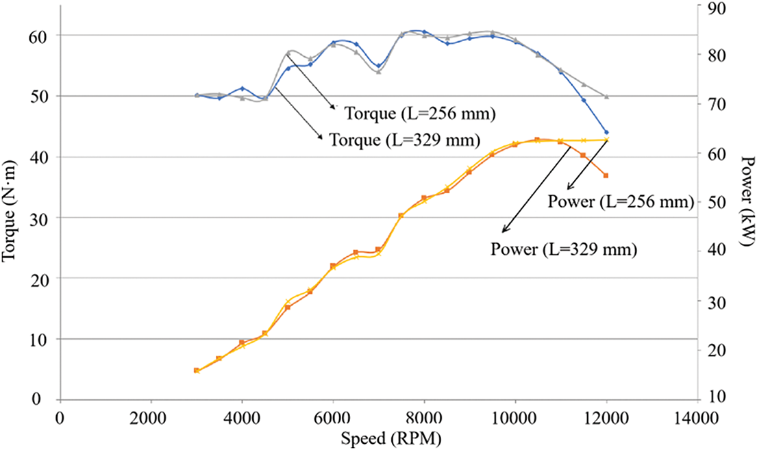
Figure 3: Comparison of the external characteristic curves of the engine with different intake manifold lengths
2.6 Numerical Simulation of Air Intake System Flow Field
The 3D model of the intake system was established using CATIA as shown in Fig. 4. During the three-dimensional CAD modeling process, the upper and lower plenums were modeled separately. Following the assembly of these components, a topological sharing method was employed. This method allows for the creation of a unified fluid domain when generating the CFD mesh, ensuring the continuity of physical quantities at the junction where the upper and lower plenums meet.
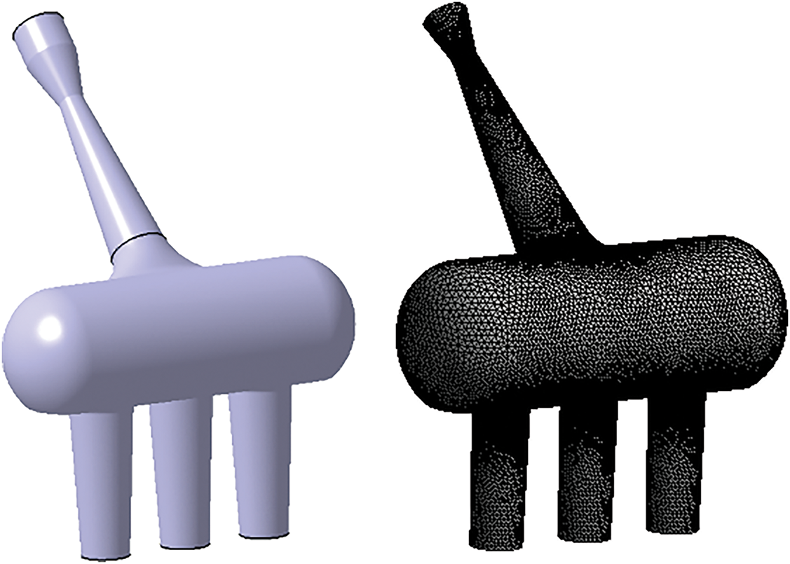
Figure 4: Geometry (left) and mesh (right) model of the intake pipe
The fluid domain of the intake system was discretized using tetrahedral meshes. A grid independence study was conducted with three distinct mesh resolutions: coarse (20,460 elements), medium (40,558 elements), and fine (50,720 elements). Comparative analysis of total mass flow rates under identical pressure differentials across inlet and outlet revealed a 1.2% discrepancy between coarse and fine meshes, while the medium and fine meshes showed only 0.2% variation. These results demonstrate that the medium mesh resolution achieves sufficient convergence accuracy with minimal computational compromise.
The selected medium mesh configuration contains 40,558 elements with 2,299,469 nodes. Mesh quality assessment confirmed compliance with numerical requirements, exhibiting a maximum distortion value of 0.79961 (below the critical threshold of 0.9). The validated mesh topology is presented in Fig. 4.
Since the pressure at the end of the intake manifold has been fluctuating and only the intake valve will be opened during the intake stroke, Matlab is used to fit the pressure curve at the end of the intake manifold in the intake stroke, and then the average value is obtained as the exit boundary condition. The pressure curve at the end of the intake manifold is shown in Fig. 5, and the mean pressure of the intake stroke at the end of the intake manifold is 91,515 Pa.
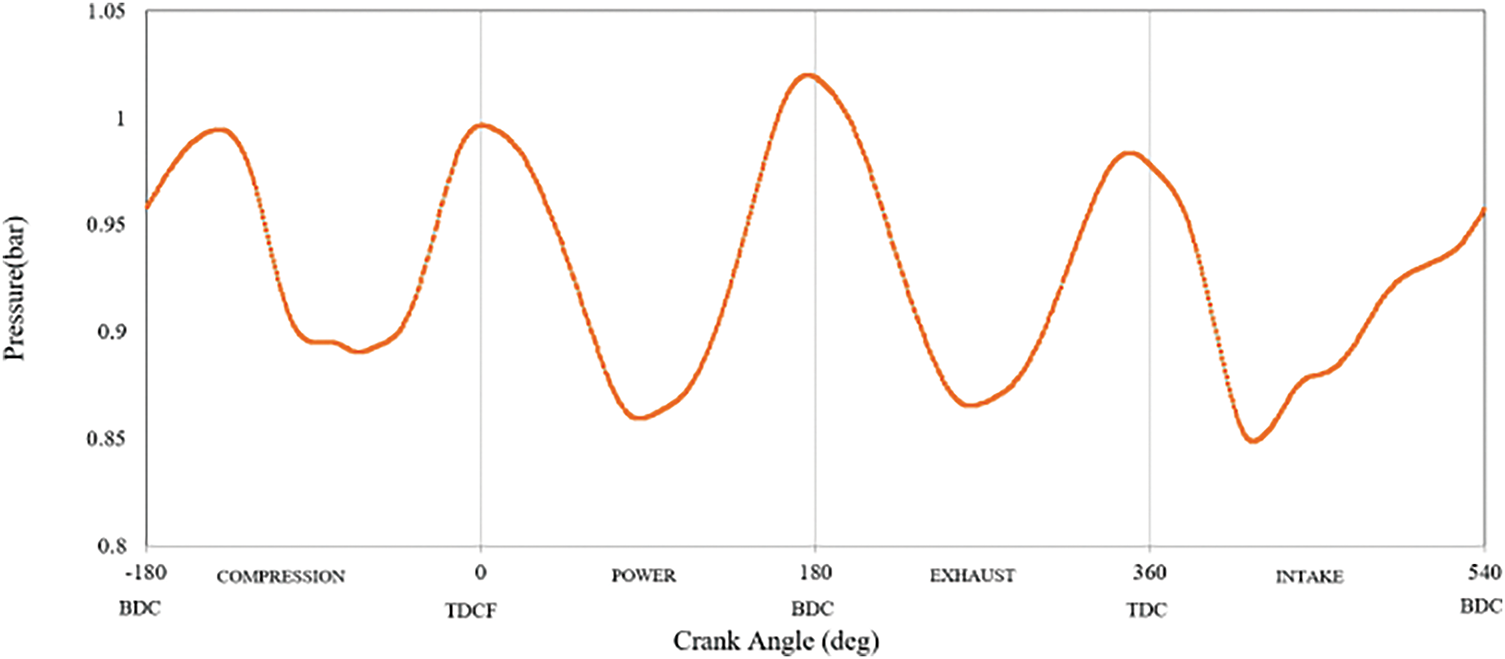
Figure 5: Pressure curve at the end of the intake manifold
The flow field analysis of the intake system was performed by Fluent. The control equations of mass, momentum, and energy are outlined in Ref. [15]. This paper adopts the boundary condition of constant pressure difference, the reference pressure is set to 10,1325 Pa, the pressure at the inlet is 0 Pa, and the outlet pressure is set to −9810 Pa from the 1D simulation of the engine. The calculation domain is discretized using tetrahedral mesh. The number of meshes is 40,558, the number of nodes is 2,299,469, and the maximum distortion of the mesh is 0.79961, the distortion is less than 0.9, which implies mesh quality meets the requirements.
The airflow in the intake system is regarded as a compressible turbulent flow [16], and the solution was obtained using a pressure-velocity solver with the Realizable
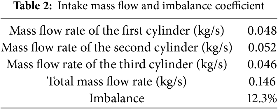
It can be seen from Fig. 6 that the airflow streamline symmetry of the entire air intake system is good, but the airflow filling in the plenum is not full. The maximum imbalance coefficient is 12.3%, and the imbalance coefficient is too large to meet the working requirements of the engine.

Figure 6: Streamline of the intake system without guide vane cascade
3 Optimal Design of Intake System
Due to the requirements of the competition rules, the structure of the air intake system is also quite different from that of ordinary vehicles. The special mechanism of the air intake system, it directly affects the air intake volume and air intake balance. In this section, the optimized structure of the air intake system was designed to improve air intake balance and charging efficiency. Furthermore, a set of electronic control systems for variable intake manifold was designed to improve the adaptability of the engine to different test items.
3.1 Structural Optimization of the Intake System
3.1.1 Optimization of Flow-Limit Valve
To improve the balance of intake air, guide vanes are added at the inlet end of the flow-limit valve. The guide vane cascade is composed of four spatially curved blades arranged in a circumferentially symmetrical pattern, fixed to the inner wall at the inlet of the flow-limit valve. The shape of the guide vane cascade is designed to effectively guide the airflow to rotate around the axis while minimizing the impact on the intake resistance.
The overall structure of the guide vane cascade is shown in Fig. 7.

Figure 7: Overall structure of the guide vane cascade
Using the same boundary conditions, the flow field analysis is carried out on the intake system with the guide vane cascade added at the inlet end of the flow-limit valve. The analysis results are shown in Table 3.

It can be seen from Fig. 8 that the airflow streamline of the entire air intake system is relatively smooth and uniform, and there is no backflow and turbulence. Due to the action of the guide vane cascade, the airflow streamline is symmetrically distributed in the center, and the airflow in the plenum is filled and filled. The total intake air mass flow is increased by 16.4%, the maximum imbalance coefficient is 1.8%, the imbalance coefficient is small, and the intake balance meets the requirements.

Figure 8: Streamline of the intake system with guide vane cascade at the inlet end of the flow-limit valve
3.1.2 Intake Manifold Optimization
In order to achieve full combustion of the mixture and improve the fuel economy of the engine, it can be achieved by adding a guide vane cascade similar to the front end of the flow-limit valve in the intake manifold, the structure of which is shown in Fig. 9. Using the same boundary condition, the flow field analysis is carried out on the intake system with the guide vanes added at the inlet end of the flow-limit valve and the intake manifold. The analysis results are shown in Table 4.

Figure 9: Manifold guide vane diagram
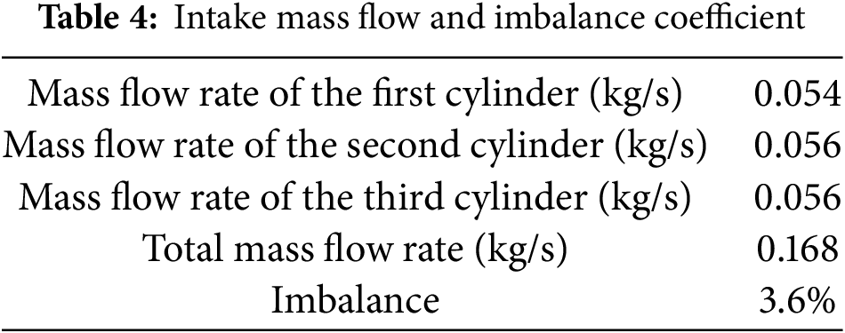
It can be seen from Fig. 10 that the airflow streamline of the entire intake system is relatively smooth and uniform, there is no backflow and turbulence, and the airflow in the plenum is filled. The total intake mass flow is increased by 15.1%, and the maximum imbalance factor is 3.6%. By comparing and analyzing the results, it can be found that when the total intake mass flow and the maximum imbalance coefficient change little, adding a guide vane in the intake manifold can greatly increase the intake swirl and make the oil-air mixing more efficient. It is sufficient to improve the combustion speed and combustion efficiency, thereby improving the power and fuel economy of the engine.
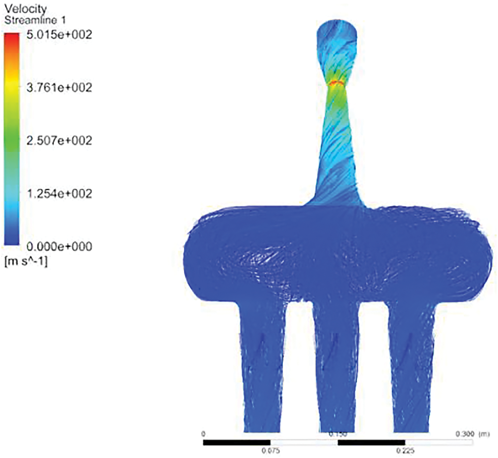
Figure 10: Streamline of the intake system with guide vane cascade at both the inlet end of the flow-limit valve and manifold
To verify whether the intake system with the diversion cascade is beneficial for improving the engine power and fuel economy, it is necessary to conduct bench experiments on the engine equipped with the new intake system. After a series of hardware modifications to the engine, the ECUs of the original engine can no longer match the engine. To calibrate the parameters of the engine, the engine control system needs to be redesigned. In this paper, an engine bench test was conducted using the MoTeC M800 ECU electronic control system. The electronic control system was developed through the formulation of a control strategy, sensor matching and calibration, and control parameter setting. The calibration of the engine’s steady-state working parameters was completed using experimental equipment from the internal combustion engine laboratory bench. Fig. 11 illustrates the construction of the experimental bench, while Fig. 12 shows a comparison between the bench test results and the initial calibration results.
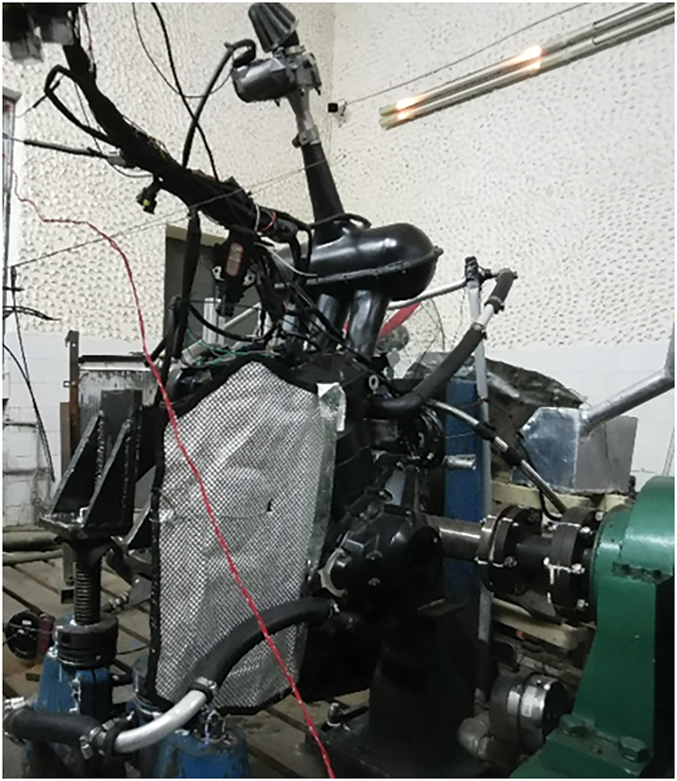
Figure 11: Engine test bench
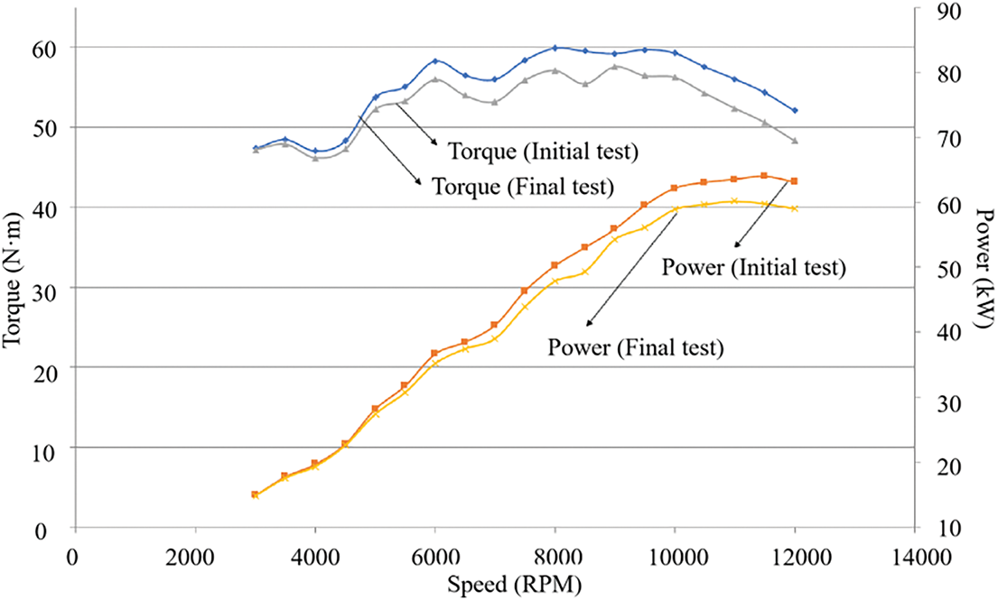
Figure 12: Comparison of bench test results and initial bench calibration results
The excess air ratio was the same as that used in the initial engine bench test, and the injection pulse width of the engine decreased following installation of the guide vane cascade. As shown in Fig. 12, the power and torque of the engine in the full speed range are higher than that in the initial bench test, especially in the medium and high speed range, where the maximum torque increases from 56.36 to 59.91 N·m and the maximum power increases from 59.16 kW to 63.94 kW. This performance augmentation originated from the optimized diversion cascade configuration which increased effective air mass flow.
3.2 Design of Intake Manifold Length Variable Control System
3.2.1 Determination of Intake Manifold Length
The competition sequence of the Formula Student China Competition is: a straight-line acceleration test, skidpad track, high-speed obstacle avoidance test, and endurance test [1]. Among them, in the straight-line acceleration test and the Fig. 13 skidpad track test, the working range of the engine speed has little change, and the time required to complete the project is less, so the intake manifold length can be designed according to its specific engine speed working range.
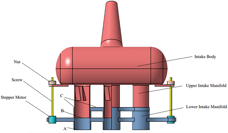
Figure 13: Structural of the the proposed variable intake manifold assembly with servo mechanism
During the straight-line acceleration test, the car starts running on a track with a total length of 75 m. The time required to complete the project is 4 to 5 s. The working speed of the engine is 8000~14600 rpm, and the average speed is 12500 rpm.
The skidpad track line connecting the two centers is both the start line and the finish line. The car starts from the starting line, runs one full circle around one of the concentric circles (each with a diameter of 18.25 m and a track width of 3.0 m between their inner and outer boundaries), and then returns to the connecting line, which is defined as one lap. The time required to complete the project is 10~16 s, the engine operating speed range is: 4000~7000 rpm, and the average speed is 5300 rpm.
According to the calculation based on the dynamic effect formula, the lengths of the intake manifold are 95 and 159 mm, respectively, for the straight-line acceleration test and the skidpad track. These lengths are chosen to optimize the resonance effect, which is enhanced by the combined inertia and wave effects of the intake system.
3.2.2 The Working Principle of the Actuator
The drive mechanism of the intake manifold length variable control system is shown in Fig. 13, and the working principle of the actuator is shown in Fig. 14. The initial length of the intake manifold is 129 mm. At this time, the overlapping length of the upper and lower sections of the intake manifold is 30 mm, that is, the BC length is 30 mm. This length is calculated based on 9000 rpm and is mainly used for high-speed obstacle avoidance testing and endurance testing. According to the competition schedule, the first thing to do is the straight-line acceleration test. The length of the intake manifold should be 95 mm, that is, the length of the BC should be 64 mm. At this time, the motor needs to drive the screw to rotate counterclockwise 17 times (looking from top to bottom). Then carry out the skidpad track test. The length of the intake manifold should be 159 mm, that is, the length of the BC should be 0 mm. At this time, the motor needs to drive the screw to rotate clockwise for 32 circles (viewed from top to bottom). Finally, the high-speed obstacle avoidance test and durability test are carried out. The length of the intake manifold should be 129 mm, that is, the length of the BC should be 30 mm. At this time, the motor needs to drive the screw to rotate counterclockwise 15 times (looking from top to bottom).

Figure 14: The working principle of the actuator
The integration of a guide vane cascade at the end of the flow-limit valve demonstrates significant performance improvements. CFD simulations reveal a 16.4% increase in total intake air mass flow rate compared to the baseline configuration. This enhancement stems from two synergistic effects: First, the cascade system accelerates gas flow disturbance, promoting faster air delivery. Second, the optimized swirling flow pattern enables rapid plenum filling, achieving an exceptionally low maximum imbalance coefficient of 1.8% across intake manifolds.
The integration of guide vanes into the intake manifold significantly enhances intake swirl, promotes uniform oil-gas mixing, and improves combustion efficiency, ultimately boosting engine power and fuel economy. CFD simulations demonstrate that the optimized design increases the total intake mass flow by 15.1% while reducing the maximum intake air imbalance coefficient to 3.6%.
By comparing the results of the bench experiments, the enhanced air intake design increased maximum engine torque by 6.3% (from 56.36 to 59.91 N·m) and boosted peak power output by 8.1% (from 59.16 to 63.94 kW). Through the real car test, the engine with the new air intake system demonstrated increased power output, leading to faster acceleration of the car on the circuit. This study validates that strategic placement of guide vanes provides a cost-effective solution for optimizing in-cylinder charge motion, balancing minimal pressure loss with significant performance gains.
Acknowledgement: The authors would like to acknowledge the HPC Center of Hubei University of Automotive Technology for providing computational resources and technical support.
Funding Statement: This research was supported by the Key Laboratory of Automotive Power Train and Electronics (Hubei University of Automotive Technology) (ZDK1201505) and Auto Parts Technology Hubei Province Collaborative Innovation Project (2015XTZX04).
Author Contributions: Yang Sun conceived the idea of the study and drafted the original manuscript. Runze Yang contributed to the final editing of the manuscript and approved the submitted version. All authors reviewed the manuscript draft and revised it critically on intellectual content. All authors reviewed the results and approved the final version of the manuscript.
Availability of Data and Materials: The data that support the findings of this study are available from the corresponding author, Runze Yang, upon reasonable request.
Ethics Approval: Not applicable.
Conflicts of Interest: The authors declare no conflicts of interest to report regarding the present study.
References
1. China Society of Automotive Engineers. Formula SAE of China Chinese Rules [Internet]. 2020 [cited 2025 May 14]. Available from: http://www.formulastudent.com.cn/documentation.html. [Google Scholar]
2. Pogorevc P, Kegl B. Optimal design of the intake system [Internet]. Maribor, Republic of Slovenia: University of Maribor, Faculty of Mechanical Engineering; 2007 [cited 2025 May 14]. Available from: https://citeseerx.ist.psu.edu/document?repid=rep1&type=pdf&doi=512a4bfa3857646a57034db02d301aaa7f357180. [Google Scholar]
3. Guo H, Fu B, Huang Z, Zhang R. Design and optimization of air intake system based on FSC. In: Journal of Physics: Conference Series. Proceedings of the 4th International Conference on Fluid Mechanics and Industrial Applications (FMIA 2020); 2020 Jun 27–28. Taiyuan, China. Bristol, UK: IOP Publishing; 2020. [Google Scholar]
4. Vaz J, Machado AR, Martinuzzi RK, Martins ME. Design and manufacture of a Formula SAE Variable intake manifold. Warrendale, PA, USA: SAE; 2017. Report No.: 2017-36-0181. [Google Scholar]
5. Alves LOFT, dos Santos MGD, Urquiza AB, Guerrero JH, de Lira JC, Abramchuk V. Design of a new intake manifold of a single cylinder engine with three stages. Warrendale, PA, USA: SAE; 2017. Report No.: 2017-36-0172. [Google Scholar]
6. Li S, Wang C, Chen D, Hao J, Zheng H, Yang C. Optimal design of FSAE racing engine intake system. In: Proceedings of China SAE Congress 2020: Selected Papers. Singapore: Springer Nature; 2022. p. 237–53. [Google Scholar]
7. Mrđa PD, Petrović V, Đinić S, Kitanović M. Development of continuously variable intake manifold for formula student racing engine. In: Proceedings of the International Congress Motor Vehicles & Motors; 2014 Oct 9–10. Kragujevac, Serbia. Kragujevac, Serbia: Faculty of Engineering, University of Kragujevac; 2014. p. 326–39. [Google Scholar]
8. Sedlacek F, Skovajsa M. Optimization of an intake system using CFD numerical simulation. Proc Manuf Syst. 2016;11(2):71. [Google Scholar]
9. Fan Y, Hu X, Guo Y, Liu R. Matching design of supercharging systems for FSAE racing engine. In: Society of Automotive Engineers (SAE)-China Congress. Singapore: Springer Nature; 2023. p. 1143–62. [Google Scholar]
10. Guo H, Zhang Z. CFD analysis and optimization of an engine with a restrictor valve in the intake system. Fluid Dyn Mater Process. 2021;17(4):745–57. doi:10.32604/fdmp.2021.014651. [Google Scholar] [CrossRef]
11. Heywood JB. Internal combustion engine fundamentals. New York, NY, USA: McGraw-Hill; 1988. [Google Scholar]
12. Vítek O, Polášek M. Tuned manifold systems–application of 1-D pipe model. SAE Trans. 2002;111:271–80. doi:10.4271/2002-01-0004. [Google Scholar] [CrossRef]
13. Queiroz JM. Estudo numérico e experimental da influência de ressonador de Helmholtz na vazão mássica em um motor de combustão interna [master’s thesis]. Belo Horizonte, MG, Brazil: Mechanical Engineering Department, Pontifical Catholic University of Minas Gerais; 2015. [Google Scholar]
14. Sun Y, Yang R. Optimal design of air intake system of FSCC triumph engine. In: Proceedings of China SAE Congress 2020: Selected Papers. Singapore: Springer Nature; 2022. p. 87–106. [Google Scholar]
15. Ferziger JH, Perić M, Street RL. Computational methods for fluid dynamics. Berlin/Heidelberg, Germany: Springer; 2019. [Google Scholar]
16. Liu S, Zhang Y. Research on the integrated intercooler intake system of turbocharged diesel engine. Int J Automot Technol. 2020;21(2):339–49. doi:10.1007/s12239-020-0032-9. [Google Scholar] [CrossRef]
17. Jun X. Optimal design and simulation research of intake system of FSAE racing engine based on intake air restriction [master’s thesis]. Chengdu, China: Xihua University; 2012. (In Chinese). [Google Scholar]
18. Zheng YJ. CAE simulation and optimization design of FSAE racing car air intake system [master’s thesis]. Xi’an, China: Chang’an University; 2014. (In Chinese). [Google Scholar]
Cite This Article
 Copyright © 2025 The Author(s). Published by Tech Science Press.
This work is licensed under a Creative Commons Attribution 4.0 International License , which permits unrestricted use, distribution, and reproduction in any medium, provided the original work is properly cited.
 Downloads
 Citation Tools