
 Submit a Paper
 Propose a Special lssue
 Open Access
ARTICLE

A Numerical Study of Fluid Velocity and Temperature Distribution in Regenerative Cooling Channels for Liquid Rocket Engines
1 College of Mechanical Engineering, Hunan University of Arts and Science, Changde, 415000, China
2 College of Furong, Hunan University of Arts and Science, Changde, 415000, China
* Corresponding Author: Liang Yin. Email:
Fluid Dynamics & Materials Processing 2025, 21(8), 1861-1873. https://doi.org/10.32604/fdmp.2025.064187
Received 07 February 2025; Accepted 30 April 2025; Issue published 12 September 2025
 View Full Text
 Download PDF
Abstract
In liquid rocket engines, regenerative cooling technology is essential for preserving structural integrity under extreme thermal loads. However, non-uniform coolant flow distribution within the cooling channels often leads to localized overheating, posing serious risks to engine reliability and operational lifespan. This study employs a three-dimensional fluid–thermal coupled numerical model to systematically investigate the influence of geometric parameters—specifically the number of inlets, the number of channels, and inlet manifold configurations—on flow uniformity and thermal distribution in non-pyrolysis zones. Key findings reveal that increasing the number of inlets from one to three significantly enhances flow uniformity, reducing mass flow rate deviation from 1.2% to below 0.3%. However, further increasing the inlets to five yields only marginal improvements (<0.1%), indicating diminishing returns beyond three inlets. Additionally, temperature non-uniformity at the combustion chamber throat decreases by 37%—from 3050 K with 18 channels to 1915 K with 30 channels—highlighting the critical role of channel density in effective thermal regulation. Notably, while higher channel counts improve cooling efficiency, they also result in increased pressure losses of approximately 18%–22%, emphasizing the need to balance thermal performance against hydraulic resistance. An optimal configuration comprising 24 channels and three inlets was identified, providing minimal temperature gradients while maintaining acceptable pressure losses. The inlet manifold structure also plays a pivotal role in determining flow distribution. Configuration 3 (Config-3), which features an enlarged manifold and reduced inlet velocity, achieves a 40% reduction in velocity fluctuations compared to Configuration 1 (Config-1). This improvement leads to a more uniform mass flow distribution, with a relative standard deviation (RSD) of less than 0.15%. Furthermore, this design effectively mitigates localized hot spots near the nozzle—where temperature gradients are most severe—achieving a reduction of approximately 1135 K.Keywords
Regenerative cooling utilizing hydrocarbon fuels as a cooling medium represents one of the most viable and widely adopted thermal protection technologies in liquid rocket engines [1–4]. Hydrocarbon fuels, which function both as propellants and coolants, must exhibit not only essential fuel characteristics—such as storage stability, high safety standards, elevated density, and significant calorific value—but also specific coolant attributes including thermal stability at elevated temperatures and efficient heat dissipation [5–7].
A comprehensive review of the existing literature, reveals that research on carbon deposition and heat transfer characteristics of hydrocarbon fuels—primarily kerosene—concentrates predominantly on three critical areas. The first area addresses the chemical mechanisms underlying cracking and coking processes. Noteworthy studies conducted by Christison et al. [8], Liu et al. [9], and Adams et al. [10,11] have thoroughly investigated the coking mechanisms associated with the thermal oxidation of kerosene. Their findings suggest that the thermal oxidation reaction primarily arises from interactions among peroxy radicals formed from various atomic components present in kerosene and other hydrocarbons. Additionally, insoluble macromolecules undergo further oxidation in environments enriched with dissolved oxygen. Building upon these insights, a detailed kinetic model for oxidative coking reactions has been proposed.
The inhibition or reduction of coking presents a significant challenge in the research related to the kerosene cooling process. Solutions to this issue can be primarily categorized into two approaches: One approach involves the incorporation of additives that effectively inhibit kerosene coking. For instance, Taylor et al. [12] utilized trace amounts of sulfides and nitrides, while Strohm et al. [13] applied tetrahydronaphthalene at a volume fraction of 2%. Additionally, Guo et al. [14] investigated the use of organic selenium compounds combined with hydrogen donors, demonstrating that these inhibitors significantly reduced both surface catalytic coking and free radical growth coking, resulting in decreased cracking rates as well as lower coking rates. The second approach focuses on minimizing coking through adjustments to operational parameters. Current research indicates that temperature and dissolved oxygen are the most influential factors affecting kerosene coking, followed by variations in heat flux, flow patterns, and working pressure.
The third aspect concerns the investigation of heat transfer characteristics in supercritical kerosene. It is essential to emphasize that kerosene typically reaches a supercritical state within the cooling channel. In this supercritical condition, the mechanisms governing fluid flow, heat transfer, and carbon deposition within the regenerative cooling channel are notably intricate. Gibreel et al. [15] proposed a symmetrical wave cooling channel design based on a secondary branch structure and examined the effects of varying wave amplitudes (0.1–0.3 mm) and transverse clearance widths (0.4–0.8 mm) on the flow and heat transfer performance of hydrogen fuel through numerical simulations. The results indicate that the symmetrical wave structure enhances fluid mixing by inducing secondary flows, resulting in a more uniform wall temperature distribution and a significant increase in the average Nusselt number (with a maximum increase of 28.23%) compared to traditional parallel wave structures. Zhang et al. [16] introduced a regenerative cooling channel design featuring a V-shaped cross-rib structure and investigated how varying rib spacings (5 mm and 2.5 mm) affect heat transfer performance through numerical simulations. The findings reveal that V-shaped cross ribs significantly enhance heat transfer efficiency by promoting secondary flow disturbances; specifically, for the configuration with 5 mm spacing, the maximum wall temperature is reduced by 4.5%, while overall heat transfer performance improves by 17.49% relative to conventional rib designs.
However, it is essential to recognize that reducing rib spacing leads to an increase in flow resistance; thus, it is imperative to achieve an optimal balance between enhanced heat transfer and pressure drop losses. This research provides valuable insights for the optimization of high-load thermal protection system designs. A comprehensive analysis reveals that researchers have conducted extensive studies on the flow characteristics, heat transfer mechanisms, and pyrolysis coking of kerosene under supercritical pressure, resulting in significant advancements in this field. In this study, we examine the flow and temperature distribution within regenerative cooling channels, while also numerically simulating the influence of structural parameters through fluid-solid/thermal coupling analysis methods.
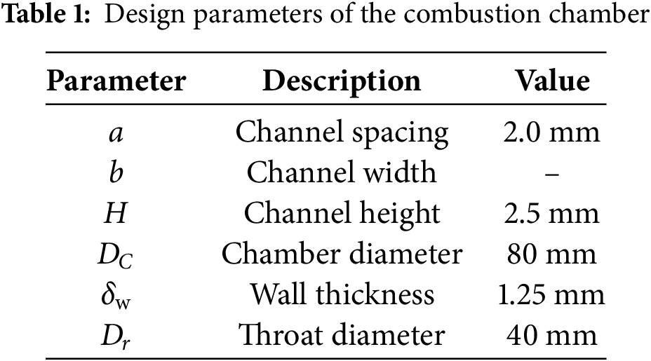
Fig. 1 depicts the fundamental configuration of a combustion chamber surrounded by cooling channels. A flange is located at the inlet, with additional inlets strategically positioned around it. In this study, the structural parameters of the regenerative cooling channels are maintained as constant. The specific values of the geometric parameters utilized in the simulation are detailed in Table 1.
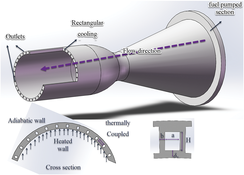
Figure 1: The configuration of combustion chamber with cooling channels
In the cooling channels of a liquid rocket engine, fuel temperatures can reach as high as 1000 K. As previously mentioned, thermal cracking and coking occur when temperatures exceed 698 K. This study primarily focuses on the characteristics of a non-pyrolysis zone. To ensure that the outlet temperature remains below 698 K, we calculate the heat flux. In order to simplify the numerical model and concentrate on the influence of structural parameters, we make the following assumptions:
(1) The fuel is in a non-pyrolysis zone.
(2) No phase transition occurs during the flow.
(3) External walls are assumed to be adiabatic, except for the heated wall.
(4) The effects of unsteady and heterogeneous thermal loads are not considered.
The mass conservation equation for the fluid region is listed as follow [17,18]:
The momentum conservation equations for the fluid region are listed as follows:
The energy conservation equation for the fluid region is listed as follows:
In the solid domain, the thermal conduction equation is numerically solved.
Considering the low-speed flow and high heat flux condition in the regenerative cooling channels, the SST k-ω turbulence model was used for calculation. The SIMPLEC algorithm and second order upwind discretization were chosen in the simulation process. In these works, regenerative cooling channel is the main flow area, the wall grid is guaranteed to be y+ < 1.0, the corresponding height of the first layer grid is set to 0.002 mm, and the grid is arranged in a gradient of 1.15.
The “mass flow inlet condition” is set as inlet boundary, and total mass flow is calculated to be 1.2 kg/s. The “pressure outlet” is imposed as the outlet boundary, and the back pressure is 4.5 MPa. The heat flux of the high-temperature gas to the wall can be calculated as Eq. (7):
In the vicinity of the combustion chamber wall, the temperature gradient is very large, and the physical parameters of kerosene change clearly, so the influence of temperature must be considered. In this work, the physical parameters are given as piecewise functions. High-temperature alloy GH3128 is used for the material of the solid, and the properties are given by the fitting polynomial [19]:
To verify the accuracy of the numerical method for flow distribution and heat transfer characteristics, we incorporate heat transfer conditions into the calculations. Moreover, we adopt experimental data from Ref. [20] for analysis and verification. U-type configurations are used in the experiment, and the simulation results are compared with the experimental results in the literature. Fig. 2 shows that the numerical method chosen in this paper can effectively predict flow distribution and heat transfer characteristics in regenerative cooling channels and has a maximum error of ~6.92%.
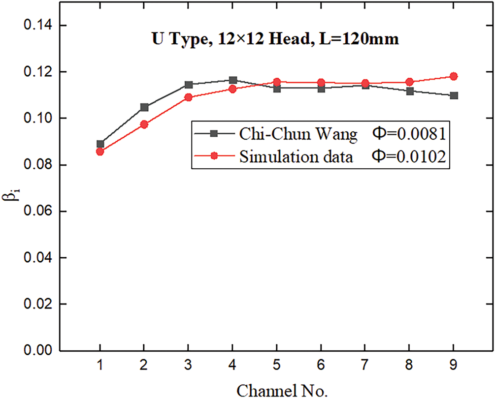
Figure 2: Verification of numerical methods
Grid convergence analysis is conducted in case 1 (N = 1). Mesh refinement is achieved by increasing the mesh count for the cooling channels. Three mesh sizes, 996,758, 1,572,681, and 1,866,360, are adopted for the computational domain. The nonuniformity coefficient of each channel is determined under the same conditions. Fig. 3 illustrates that the maximum discrepancy between the fine grid and the medium grid is 1.32%, indicating that the medium grid is suitable for the calculations.
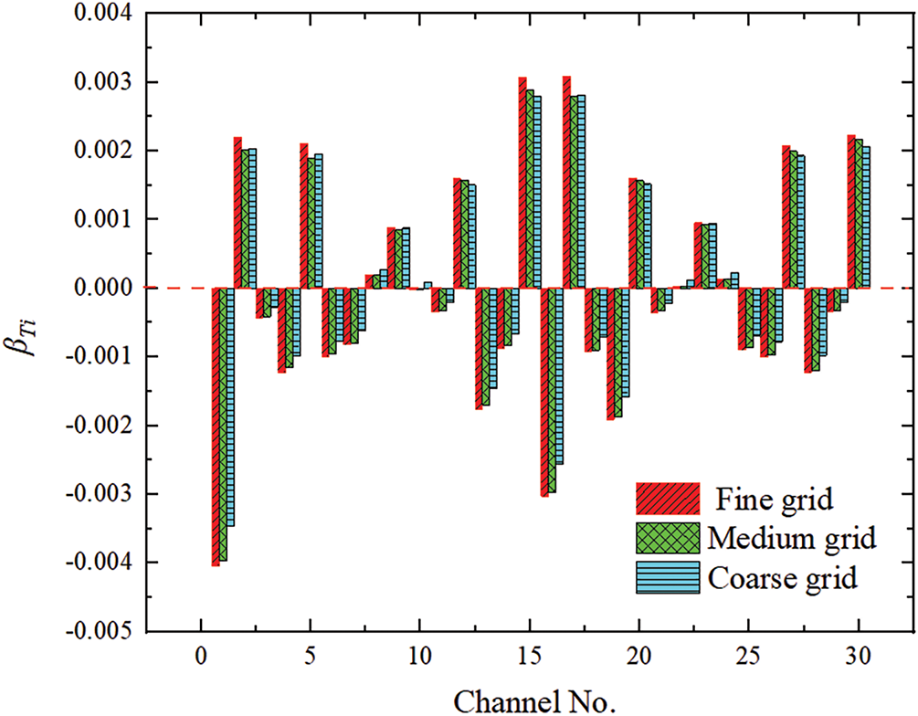
Figure 3: Grid independence study
The uniformity of mass flow rate distribution is characterized using the relative standard deviation (RSD). Under uniform heat flux conditions, the mass flow rate distribution becomes increasingly uniform as RSD decreases. The definition of the RSD of mass flow rate was established in a previous study [21]:
where, n is the number of the channels.
where,
The RSD of temperature is defined:
where,
3.1 The Effects of Inlet Number
In an engine test, weight is reduced by using only one inlet for regenerative cooling. The geometric structure is one of the primary factors affecting mass flow distribution. As the number of inlets increases, flow distribution changes. Simulations are conducted using one, three, and five inlets. These inlets are evenly distributed around a flange. Fig. 4 displays the configurations with different numbers of inlets.
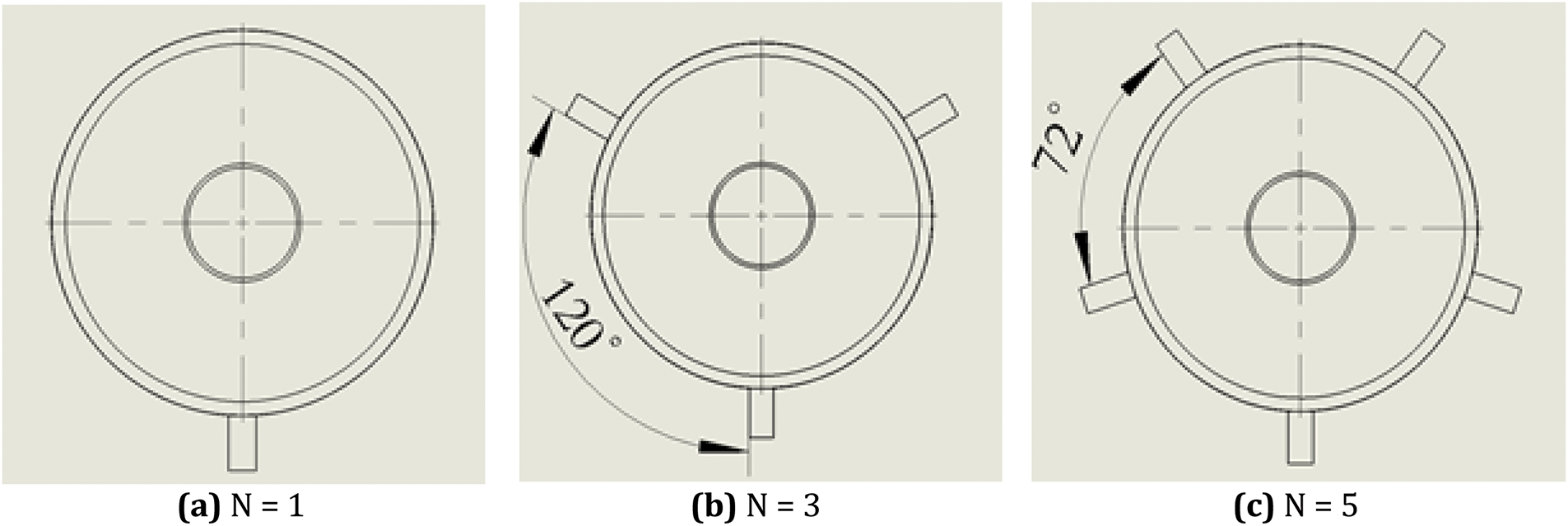
Figure 4: The configurations with different inlet number
Fig. 5 illustrates the mass flow rate nonuniformity coefficient with different numbers of inlets. As the number of inlets increases from one to three, the mass flow rates in the channels become equal. With an increase from three to five inlets, the uniformity of flow distribution further improves, but the improvement is minimal. Therefore, for subsequent simulations or experiments, increasing the number of inlets for regenerative cooling to three ensures the uniformity of flow distribution and prevents the ablation of individual channels due to extremely low mass flow rates.
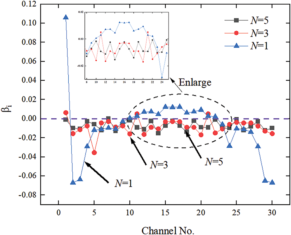
Figure 5: The mass flow rate non-uniformity coefficient with different N
Fig. 6 illustrates the outlet temperature nonuniformity coefficient for each channel. The temperature of the channel near the inlet is low, and the temperature difference among the other channels is minimal. Additionally, the left and right channels near the inlet have a lower mass flow rate, resulting in higher temperatures.
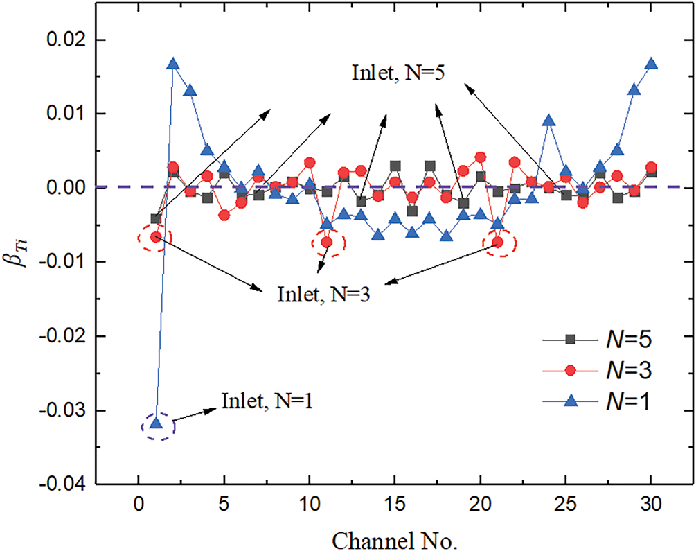
Figure 6: The temperature non-uniformity coefficient with different N
Analysis of the temperature distributions in different outlet sections (Fig. 7) reveals a decrease in temperature (at X = 0 mm, X = −200 mm) as the number of inlets increases. The temperature distribution in the combustion chamber is more uniform in the same section position, effectively cooling the walls of the combustion chamber and the throat. Especially in the throat, the temperature uniformity has been effectively improved. Although increasing the number of inlets may not improve flow distribution uniformity, it can effectively reduce wall temperatures. At N = 5, the deviation of mass flow rates among channels ranges from 0.1% to 0.3%. Consequently, the mass flow rate in all channels can be considered essentially the same.
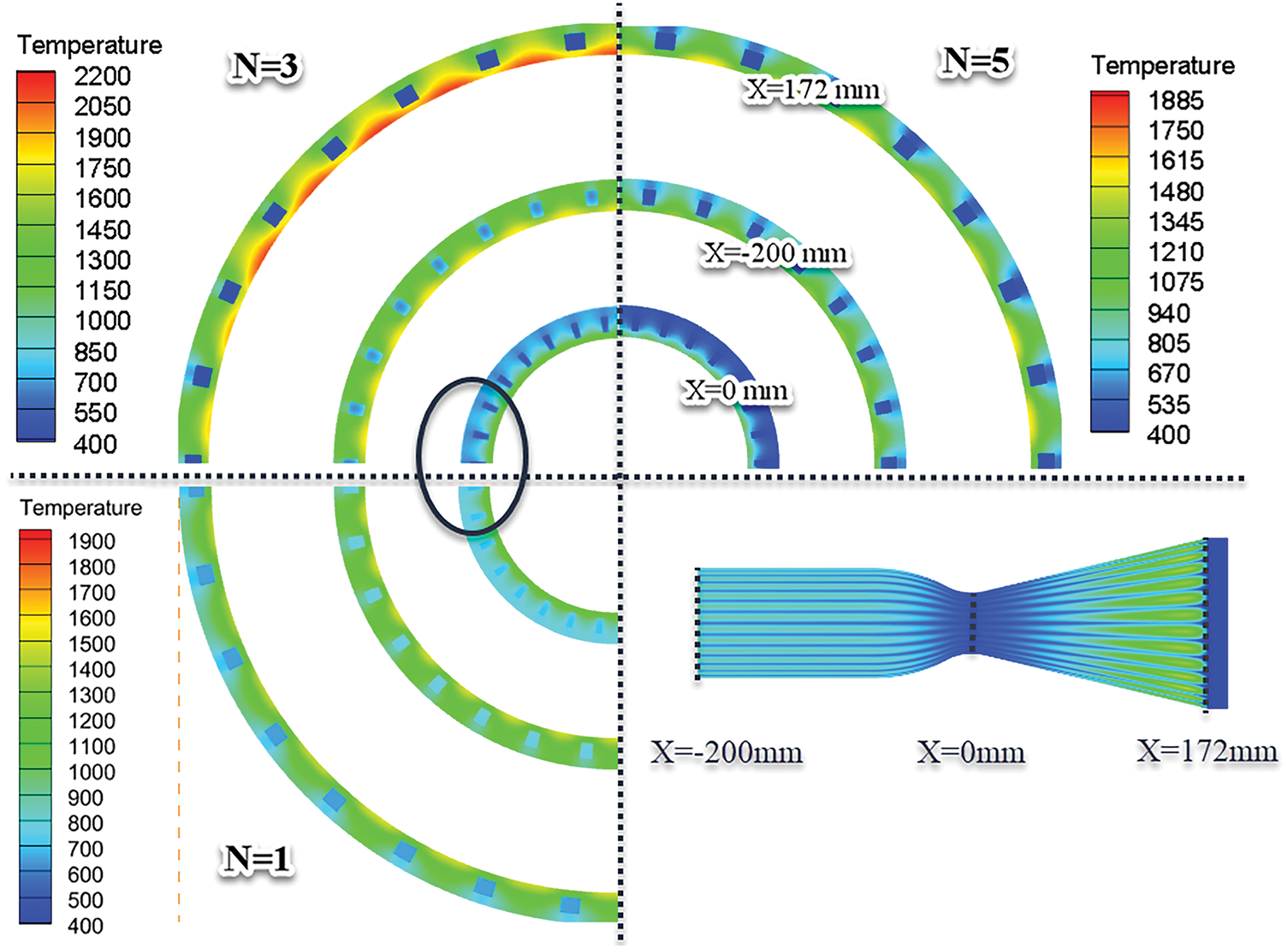
Figure 7: Temperature distribution in different cross sections
3.2 The Effects of Channel Number
The number of channels is a crucial design parameter in regenerative cooling systems. When there are too few cooling channels, the cooling capacity is insufficient. Conversely, when there are too many cooling channels, the pressure drop becomes significantly larger, which affects the entire supply system. Furthermore, inadequate cooling capacity due to excessive thermal load will inevitably lead to a “positive feedback” effect on the mass flow rate of cooling channels, considerably affecting the engine’s operational processes. Therefore, establishing an appropriate number of channels is essential. Fig. 8 displays configurations with different numbers of channels. The simulation includes 18, 24, and 30 channels and three inlets.
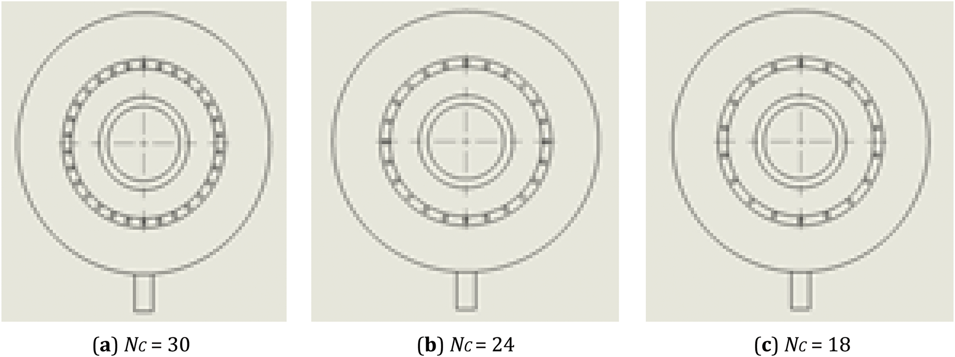
Figure 8: The configurations with different channel number
Fig. 9 displays fuel outlet temperatures for different numbers of channels. Analysis of the cooling channels at the same circumferential angle (Fig. 9) reveals that the temperature distribution can be divided into three parts according to the number of inlets. Temperatures are lower near the inlets owing to the higher mass flow rates. Other channels feature only slight temperature variations, indicating uniformity. An increase in the number of channels results in lower outlet temperatures, as the heat absorption capacity of the fuel remains constant. Therefore, a reduction in the number of cooling channels can result in effective cooling by increasing the heat absorption capacity of the coolant. The number of channels has only a slight effect on flow distribution. After evaluating the cooling capacity and pressure drop, it is recommended to utilize 24 channels (with Nc = 30 resulting in excessive pressure drop and Nc = 18 providing insufficient cooling). However, the design must be optimized based on the specific heat load requirements.
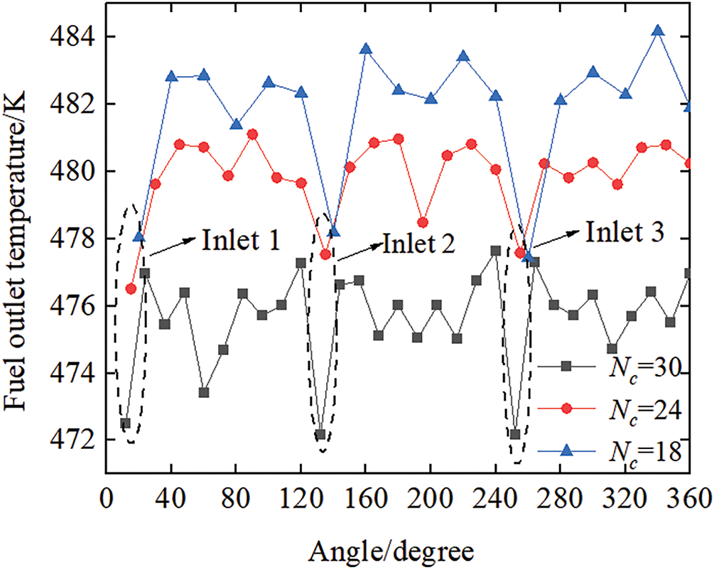
Figure 9: The fuel outlet temperature with different channel number
Fig. 10 presents the temperature contours of the combustion chamber with different numbers of channels. The number of channels significantly influences the cooling of the combustion chamber. The maximum temperature in the case of Nc 18 is 3050 K, whereas Nc 30 exhibits a value of 1915 K. In terms of temperature contours within the combustion chamber, Nc 30 exhibits a better cooling effect than the other cases. Temperature differences are mainly evident in the nozzle, with a maximum temperature difference of ~1135 K.
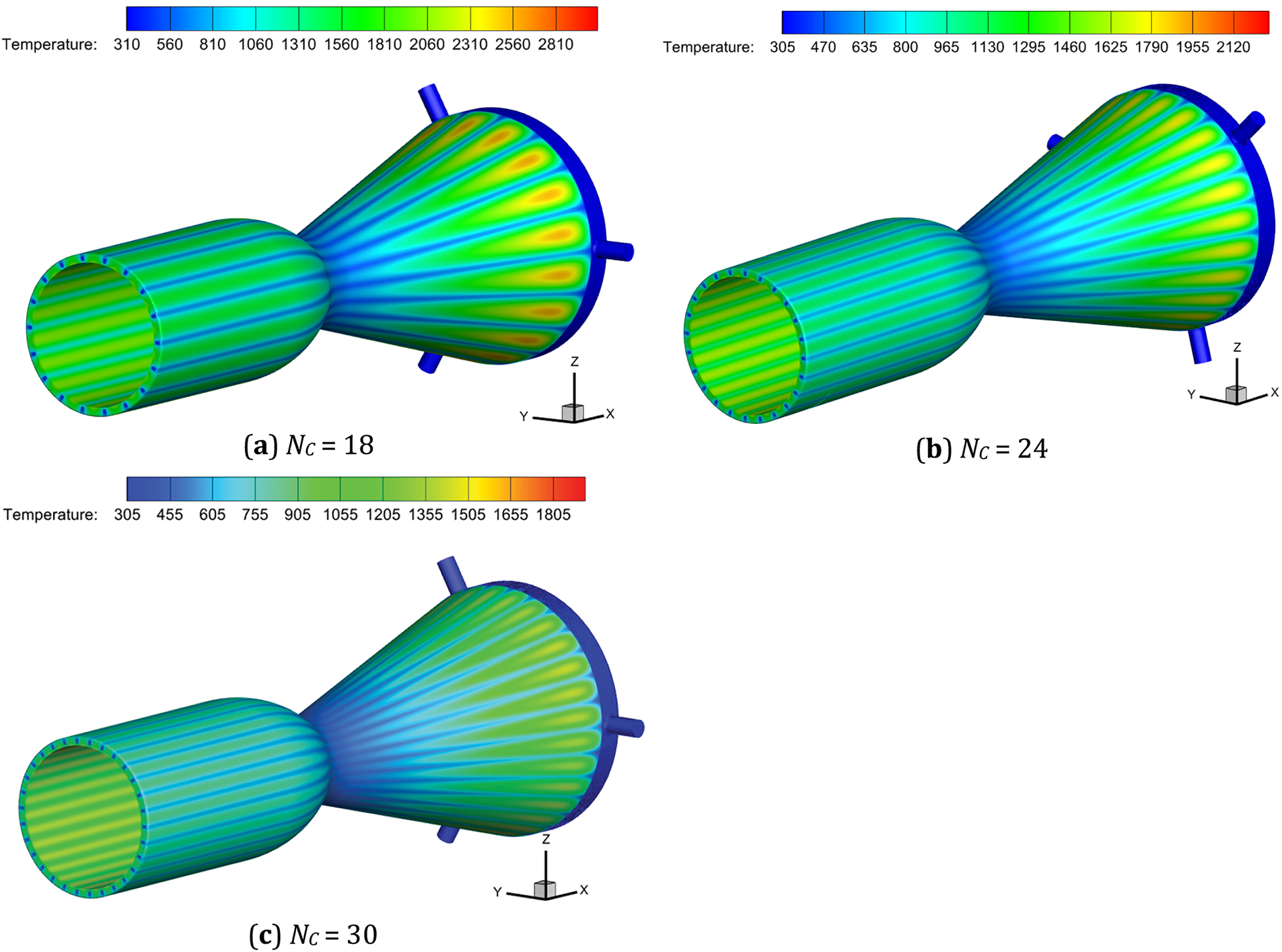
Figure 10: The temperature contours of the combustion chamber with different channel number
Fig. 11 illustrates the nonuniformity coefficient of cooling channels for Configs-1–3. The inlet manifold structure considerably influences the mass flow rates of the cooling channels. In all cases, the flow distributions exhibit significant nonuniformity in the cooling channels near the inlets. As the pumped section volume increases, traffic is evenly distributed. A similar conclusion can be drawn from the temperature nonuniformity coefficient of each channel (Fig. 12). The results suggest that the inlet manifold structure plays a crucial role in flow distribution, and a larger inlet manifold (Config-3) is preferred.
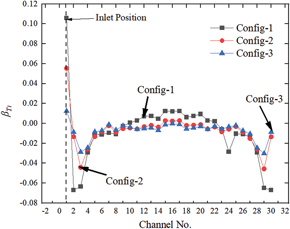
Figure 11: The mass flow rate non-uniformity coefficient with different inlet manifold structure
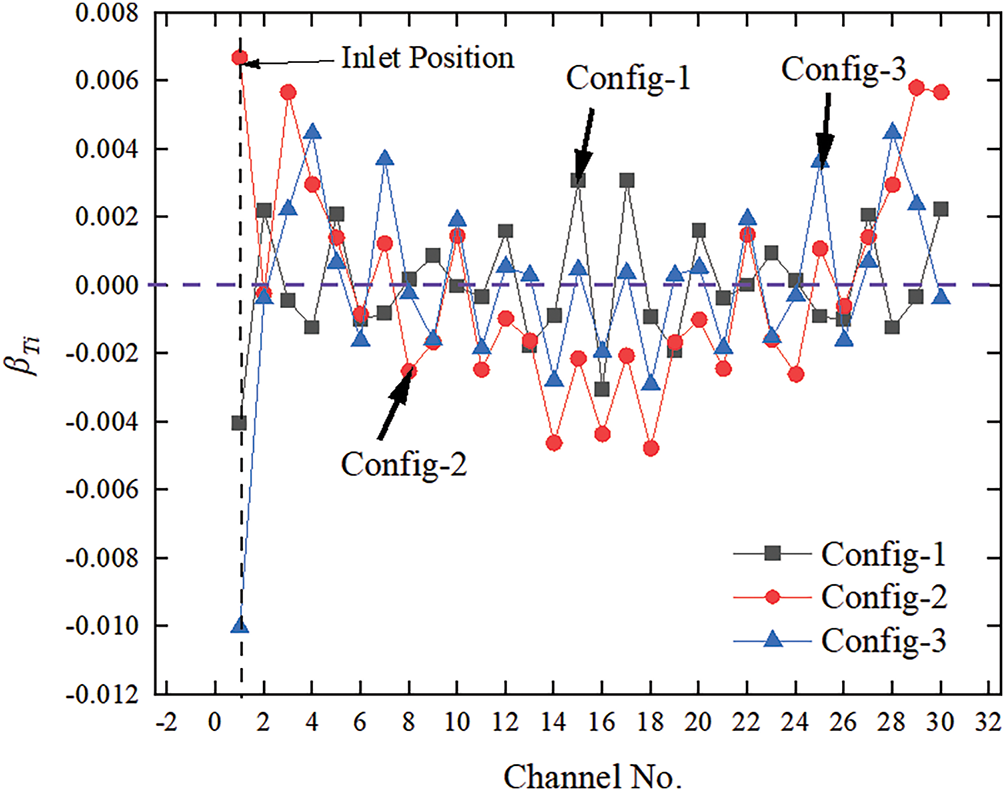
Figure 12: The temperature non-uniformity coefficient with different inlet manifold structure
3.3 The Effects of Inlet Manifold Structure
Fig. 13 illustrates the velocity and pressure distribution in the inlet manifold. On the plane of symmetry in the inlet manifold, velocity decreases significantly owing to changes in the flow area. The velocity distribution in Config-3 is more uniform, and a lower flow velocity is favorable for fluid distribution. Regarding the pressure distribution, compared with Config-2 and Config-3, Config-1 exhibits significant fluctuations in different cooling channels, thereby reducing uniformity in the cooling channels.
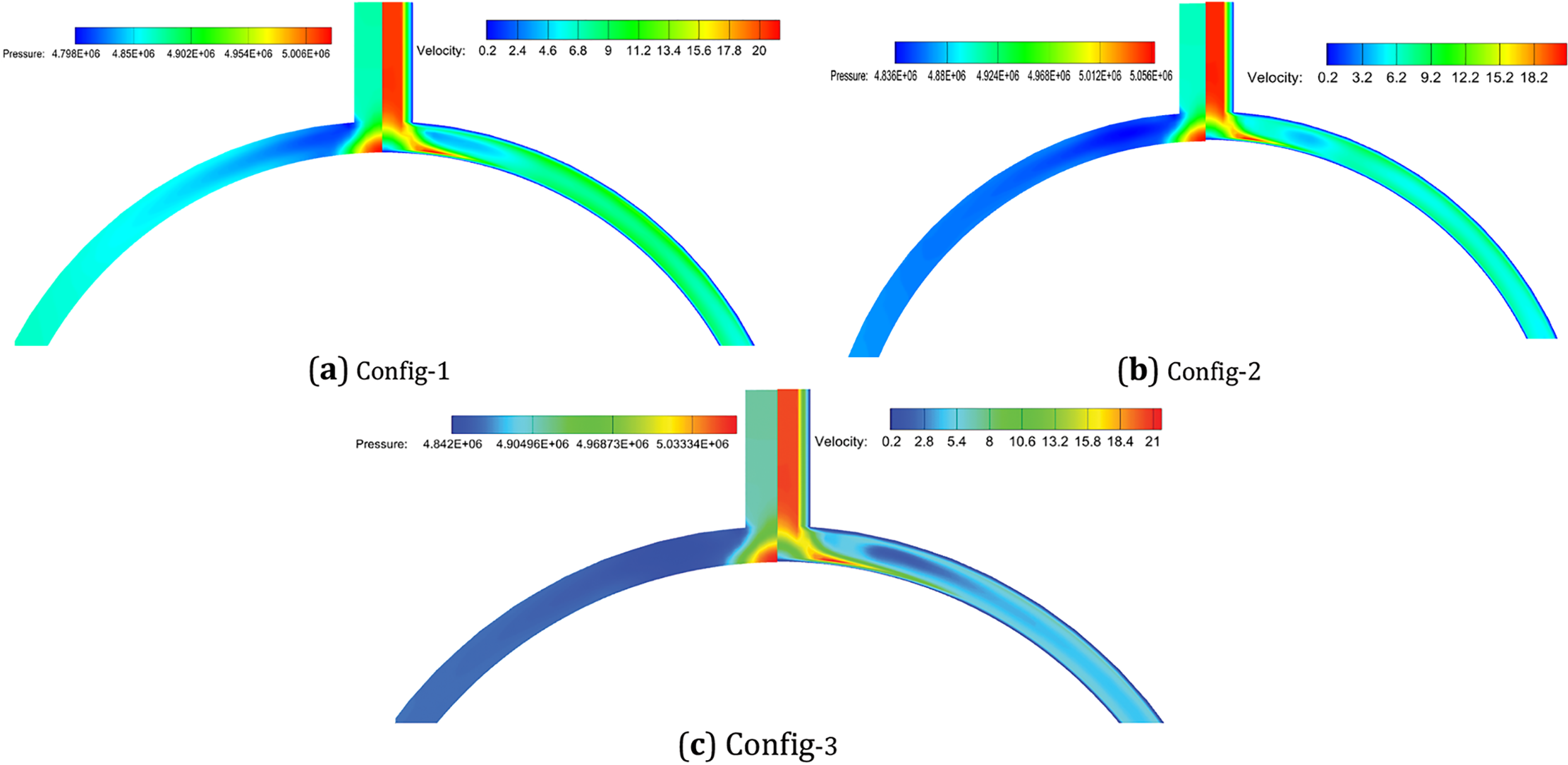
Figure 13: The velocity and pressure distribution with different inlet manifold structure
Numerically, the heat transfer and flow distribution properties of regenerative cooling are investigated. This study examines the impacts of various geometric parameters, such as the quantity of inlets and channels, as well as the configuration of the inlet manifold. The fluctuations in the nonuniformity coefficient are exposed in this article. The following are some conclusions that can be derived from this study.
1. Effectively enhancing the uniform distribution of flow and thermal burden is the quantity of inlets. Slight variations in flow distribution manifest as the quantity of inlets escalates; therefore, it is advisable to augment the number of inlets to three in order to avert the obliteration of channels by an exceedingly minute mass flow.
2. Efficient cooling is achieved through the augmentation of channel count, albeit with negligible repercussions on flow distribution. Nc = 18 demonstrates a maximal temperature of 3050 K, whereas Nc = 30 attains a temperature of 1915 K. The cooling effect of Nc = 30 is superior to that of the other cases.
3. The fluid distribution is improved by the reduced flow velocity in Config-3, which results in a more uniform velocity distribution. The flow distribution is notably impacted by the structure of the inlet manifold; therefore, a sizable inlet manifold (Config-3) is favored.
4. Future research should consider the impact of fuel fracture and coking in regenerative cooling channels, given the high heat flux in a liquid rocket engine.
Acknowledgement: Not applicable.
Funding Statement: This research was supported by the Key project of Hunan Provincial Education Department (Grant Number: 22A0485); The Natural Science Foundation of Hunan (Grant Number: 2024JJ5293); The Key project of Hunan University of Arts and Science (Grant Number: 23ZZ08).
Author Contributions: The authors confirm contribution to the paper as follows: original manuscript draft: Liang Yin; analysis and interpretation of results: Liang Yin and Jie Ding; manuscript writing and revisions: Huanqi Zhang and Mehdi Khan. All authors reviewed the results and approved the final version of the manuscript.
Availability of Data and Materials: Not applicable.
Ethics Approval: Not applicable.
Conflicts of Interest: The authors declare no conflicts of interest to report regarding the present study.
References
1. Elmouazen H, Zhang X, Gibreel M. Enhanced heat transfer and flow topology of hydrogen regenerative-cooling channels with novel X-shape ribs. Int J Hydrogen Energy. 2023;48(82):32110–24. doi:10.1016/j.ijhydene.2023.04.330. [Google Scholar] [CrossRef]
2. Kim JS, Seo SH, Ban CG, Kim KH. Conjugate heat transfer analysis of a ram/scramjet with thermal decomposition of the regenerative cooling channel. Int J Heat Mass Transf. 2025;244(3):126901. doi:10.1016/j.ijheatmasstransfer.2025.126901. [Google Scholar] [CrossRef]
3. Kim JS, Seo SH, Lee M, Kim H, Kim KH. Optimal design of regenerative cooling channels for a ram/scramjet dual-mode aircraft using conjugate heat transfer analysis. Aerosp Sci Technol. 2025;159:109978. doi:10.1016/j.ast.2025.109978. [Google Scholar] [CrossRef]
4. Yin L, Jiaqiang E, Ding J, Li Y. An experimental study on the spray characteristics of splash platelet injector. Acta Astronaut. 2021;181:377–83. doi:10.1016/j.actaastro.2021.01.046. [Google Scholar] [CrossRef]
5. Kose YM, Celik M. Regenerative cooling comparison of LOX/LCH4 and LOX/LC3H8 rocket engines using the one-dimensional regenerative cooling modelling tool ODREC. Appl Sci. 2024;14(1):71. doi:10.3390/app14010071. [Google Scholar] [CrossRef]
6. Perakis N, Preis L, Haidn OJ. Wall heat flux evaluation in regeneratively cooled rocket thrust chambers. J Thermophys Heat Transf. 2021;35(1):127–41. doi:10.2514/1.T6056. [Google Scholar] [CrossRef]
7. Ling L, Ze YI, Yu X. Flow and heat transfer characteristics in PCHE channels under airborne conditions. J Nav Aeronaut Astronaut Univ. 2021;36(2):173–8, 221. [Google Scholar]
8. Christison KM, Boursalian GB, Franz AH. Fundamental study of jet fuel oxidative deposit formation. Fuel. 2024;358(Pt B):130343. doi:10.1016/j.fuel.2023.130343. [Google Scholar] [CrossRef]
9. Liu Z, Yuan S, Gong S, Liu G. Long-term thermal oxidative deposition of RP-3 jet fuels: mechanism and modeling. Fuel. 2021;303(Suppl C):121250. doi:10.1016/j.fuel.2021.121250. [Google Scholar] [CrossRef]
10. Adams C, Alborzi E, Yong X, Blakey S, Meijer AJ, Pourkashanian M. Experimental and quantum chemical investigation into the nature of jet fuel deposition on surfaces. Fuel. 2024;358(Pt B):130101. doi:10.1016/j.fuel.2023.130101. [Google Scholar] [CrossRef]
11. Adams C, Alborzi E, Meijer AJ, Hughes KJ, Pourkashanian M. Mechanistic investigation into the formation of insolubles in bulk fuel jet fuel using quantum chemical and experimental techniques. Fuel. 2023;334(Pt 1):126202. doi:10.1016/j.fuel.2022.126202. [Google Scholar] [CrossRef]
12. Taylor WF. Deposit formation from deoxygenated hydrocarbons. II. Effect of trace sulfur compounds. Ind Eng Chem Prod Res Dev. 1076;15(1):64–8. doi:10.1021/i360057a012. [Google Scholar] [CrossRef]
13. Strohm JJ, Ahin O, Song CS, Eser S. Significant reduction of carbon deposit by hydrogen donor addition to JP-8 jet fuel at high temperatures. ACS Div Fuel Chem. 2004;49(1):34. [Google Scholar]
14. Guo W, Zhang X, Liu G, Wang J, Zhao J, Mi Z. Roles of hydrogen donors and organic selenides in inhibiting solid deposits from thermal stressing of n-dodecane and Chinese RP-3 jet fuel. Ind Eng Chem Res. 2009;48(18):8320–7. doi:10.1021/ie900735c. [Google Scholar] [CrossRef]
15. Gibreel M, Zhang X, Elmouazen H. Enhancement of heat transfer and hydrogen fuel flow characteristics in a wavy cooling channel with secondary branch design. Int J Therm Sci. 2023;193(Suppl C):108513. doi:10.1016/j.ijthermalsci.2023.108513. [Google Scholar] [CrossRef]
16. Zhang Q, Xue T, Zhang X. Advancing heat transfer efficiency: v-shape crossed structures in regenerative cooling channels for rocket engines. Int Commun Heat Mass Transf. 2024;158(36):107921. doi:10.1016/j.icheatmasstransfer.2024.107921. [Google Scholar] [CrossRef]
17. dos Santos MAE, Passaro A, Ribeiro GB. Entropy generation minimization of a regenerative cooling system for a scramjet inlet. Therm Sci Eng Prog. 2025;57(17):103172. doi:10.1016/j.tsep.2024.103172. [Google Scholar] [CrossRef]
18. Yin L, Ding J, Li Y. Numerical study on the flow and mixing characteristics of splash platelet injector. J Hunan Univ Arts Sci Sci Technol. 2021;33(4):53–7. doi:10.1016/j.actaastro.2021.01.046. [Google Scholar] [CrossRef]
19. Zhang M, Sun B, Song J. Effect of inlet and outlet manifolds on regenerative cooling in LOX/methane thrust chambers. J Therm Sci. 2021;30(2):517–29. doi:10.1007/s11630-020-1312-4. [Google Scholar] [CrossRef]
20. Sun HY. Investigation on kerosene’s regenerated cooling of supersonic combustion chamber [master’s thesis]. Changsha, China: National University of Defense Technology; 2018. [Google Scholar]
21. Wang C, Yang K, Tsai J, Chen I. Characteristics of flow distribution in compact parallel flow heat exchangers, part I: typical inlet header. Appl Therm Eng. 2011;31(16):3226–34. doi:10.1016/j.applthermaleng.2011.06.004. [Google Scholar] [CrossRef]
Cite This Article
 Copyright © 2025 The Author(s). Published by Tech Science Press.
This work is licensed under a Creative Commons Attribution 4.0 International License , which permits unrestricted use, distribution, and reproduction in any medium, provided the original work is properly cited.
 Downloads
 Citation Tools