
 Submit a Paper
 Propose a Special lssue
 Open Access
ARTICLE

Particle-Size-Dependent Reactivity and Graded Utilization of Water-Cooled Ferronickel Slag in Cement-Based Materials
1 School of Civil Engineering, Architecture and Environment, Hubei University of Technology, Wuhan, China
2 Key Laboratory of Intelligent Health Perception and Ecological Restoration of Rivers and Lakes, Ministry of Education, Hubei University of Technology, Wuhan, China
3 Centre for Advanced Innovation Technologies, VSB-Technical University of Ostrava, Ostrava-Poruba, Czech Republic
* Corresponding Author: Xingyang He. Email:
(This article belongs to the Special Issue: Low-carbon Civil Engineering Materials: Materials Processing, Fluids and Medium Transport)
Fluid Dynamics & Materials Processing 2026, 22(6), 1 https://doi.org/10.32604/fdmp.2026.081547
Received 04 March 2026; Accepted 27 May 2026; Issue published 30 June 2026
 View Full Text
 Download PDF
Abstract
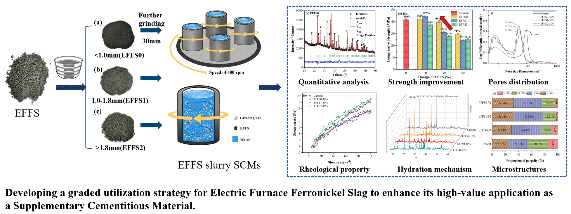
The utilization of water-cooled electric furnace ferronickel slag (EFFS) in concrete remains constrained by its intrinsically low pozzolanic reactivity as a supplementary cementitious material (SCM) and its inadequate volumetric stability when employed as aggregate. This study systematically investigates the compositional characteristics of this slag across different particle-size fractions and proposes a wet-grinding activation strategy to enhance its pozzolanic performance. In particular, cement pastes incorporating 10%, 30%, and 50% ultrafine EFFS derived from three original size fractions are comprehensively evaluated in terms of rheological behavior, compressive strength, hydration characteristics, and microstructural evolution. The results demonstrate pronounced size-dependent differences in phase composition. The amorphous phase content of EFFS particles smaller than 1.0 mm (EFFS0) reaches 54.04%, which is 19.72% higher than that of particles larger than 1.8 mm (EFFS2). The higher amorphous content leads to enhanced pozzolanic activity and improved mechanical performance. Mortars containing 30% ultrafine EFFS0 exhibit favorable strength development, with the 28-day compressive strength reaching 96% of that of the plain cement control and showing a 29% increase relative to the corresponding EFFS2 mixture. Based on these findings, a graded utilization strategy for water-cooled EFFS is proposed: The finer and more reactive fractions are suitable for SCM applications after activation, whereas the coarser fractions are more appropriate for non-cementitious applications, such as aggregate utilization.Graphic Abstract
Keywords
Concrete ranks as the second most widely consumed material globally, with an annual consumption of approximately 30 billion tonnes, surpassed only by water [1]. The production of 100 million cubic meters of concrete will require 0.25–0.35 billion tons of cement [2,3]. The cement industry is associated with substantial CO2 emissions and energy consumption, leading to significant resource depletion and exacerbation of the greenhouse effect. Therefore, mitigating the environmental impact of the cement industry is of considerable importance. Promising strategies include the adoption of alternative fuels [4], waste heat generation [5] and alternative materials [6,7]. Among these, the use of supplementary cementitious material (SCM) has been demonstrated as one of the most effective approaches [8,9]. Plenty of solid wastes have been proven to have excellent properties, including metakaolin [10], slag [11] and silica fume [12]. The pozzolanic activity of SCM is a critical factor influencing the extent to which cement can be replaced [13,14,15]. Enhancing this activity is therefore essential for reducing associated carbon emissions and energy consumption.
During the beneficiation and smelting process of nickel ore, a large amount of ferronickel slag is generated, accounting for approximately 50% to 75% of the raw ore. According to statistics, about 14 t of this slag are produced as a by-product for every ton of ferronickel refined. Currently, the annual global output of ferronickel slag is considerable, with China alone producing over 30 million tons per year. However, the comprehensive utilization rate of this slag remains below 10% at present. Therefore, to maximize resource utilization, it is urgently necessary to explore and develop economical and feasible new approaches for the application of ferronickel slag [16,17]. The mineral component of EFFS is dominated by forsterite (Mg2SiO4), which is a stable crystalline phase that rarely participates in pozzolanic reactions [18,19,20,21]. Owing to its low water absorption, high density, and high hardness, EFFS has found limited applications in areas such as ceramics [22], refractory [23], magnesium phosphate cement [24], and other construction products.
The feasibility of using EFFS as SCM to replace cement has been verified. It was demonstrated that EFFS and natural pozzolan could be used as SCM, meeting standard specifications when replacing up to 20% of cement [25]. However, the low pozzolanic activity of EFFS leads to a considerable decline in compressive strength when incorporated at higher replacement levels. A 42% reduction was observed for 90 d compressive strength of mortars when 50% cement was substituted by EFFS [26]. Similar results were observed: the compressive strength dropped sharply from 52.1 MPa to 27.8 MPa when the EFFS content increased from 30% to 50% [27].
To enhance the EFFS incorporation rate in concrete, grinding technology has been employed. It was found that mechanical refinement of EFFS improved the mechanical properties of blended cement to some extent, primarily due to enhanced reactivity and nucleation effects [28,29]. Nevertheless, the performance of the resulting cementitious system remained unsatisfactory. In a further attempt to improve early-age performance, steam curing was applied and found that steam curing had a positive effect on the compressive strength for the composites with 5% and 10% EFFS [30]. While steam curing positively influenced early strength at low EFFS replacement levels (5% and 10%), it did not prevent significant strength reduction in high-volume EFFS mixtures [31]. It could be concluded that although mechanical grinding and steam curing partially enhance the reactivity of EFFS, the inherently low amorphous content fundamentally limits its effectiveness as an SCM at high substitution rates.
Additionally, researchers also attempted to use EFFS as a precursor for geopolymer binders [32,33]. Studies on hybrid fly ash-EFFS hybrid precursors have indicated that incorporating 60% EFFS leads to an extended setting time and a significant reduction in strength [34]. A similar result was reported, a noticeable decline in strength when 50% of the slag precursor was replaced by EFFS [35]. Although the low early reactivity of EFFS-based precursors can be partially mitigated by blending with more reactive materials such as slag or fly ash in alkali-activated systems [36,37], this approach does not fully resolve the issue. It was found that EFFS alone cannot generate sufficient reaction products to meet mechanical property requirements. This limitation is primarily due to the intrinsically low reactivity of EFFS.
Recent studies have also explored the utilization of EFFS as an aggregate in mortars and concrete [19,38]. For instance, substituting 30% of manufactured sand with EFFS particles in the size ranges of 2.36–1.18 mm and 1.18–0.60 mm enhanced the concrete strength [39]. This is consistent with the previous results [40], which found that using 25% EFFS aggregates resulted in satisfactory compressive strength, sulfate attack resistance, and chloride penetration resistance. Water-cooled EFFS is widely recognized for its low water absorption, high strength, and superior deformation resistance, making it a promising alternative to natural sand [41]. However, a comparative study of air-cooled and water-cooled EFFS aggregates revealed that the water-cooled variant poses a higher risk of alkali-silica reaction (ASR) [42]. Similarly, it was found that the alkali-silica reaction of air-cooled EFFS and water-cooled EFFS aggregates in alkali-activated slag mortars by accelerated mortar bar test, concluding that water-cooled EFFS exhibits more pronounced ASR expansion than its air-cooled counterpart [43]. This difference is attributed to the higher reactivity of water-cooled EFFS, resulting from the rapid cooling process that promotes the formation of amorphous phases [44,45]. These stability concerns significantly restrict the widespread application of water-cooled EFFS as an aggregate in concrete. So, the utilization of water-cooled EFFS presents significant challenges, particularly its low pozzolanic activity when used as a cementitious material and its poor stability as aggregates.
Wet grinding is a promising activation method for industrial slag, which enables slag refinement with lower energy consumption, promotes ion dissolution, and enhances slag reactivity. Compared to conventional dry grinding, wet grinding reduces particle agglomeration, enhances ion dissolution, and achieves finer particle size with lower energy consumption. It also promotes early pozzolanic reactivity due to pre-hydration or surface activation effects. The feasibility has been verified for the activation of lithium slag and fly ash [46,47,48,49,50], but its application in EFFS activation remains limited.
Unlike previous studies that directly wet-ground raw EFFS, this work first separates EFFS by particle size to reveal the intrinsic reactivity difference caused by cooling rate, and then applies wet grinding to each fraction under identical conditions. This decouples the effects of original particle size from those of grinding.
Considering that the cooling process of EFFS particles, which is influenced by their size, may directly influence their phase composition and reactivity. This study systematically investigated the compositional characteristics and reactivity of EFFS across different particle size fractions. Wet grinding was employed to enhance the reactivity of EFFS. The raw EFFS was first sieved into three fractions with similar mass by size ranges: <1.0 mm, 1.0–1.8 mm, and >1.8 mm. Each fraction was then individually ground to obtain superfine powders with closely matched particle size distributions, minimizing variations in fineness unrelated to the original cooling. Cementitious specimens incorporating 10%, 30%, and 50% ultrafine EFFS by mass were prepared to evaluate their performance. The compressive strength, hydration and microstructures of EFFS-cement were investigated by isothermal calorimetry, XRD, TG, SEM, and MIP.
2 Materials and Experimental Methods
The cement used in this study was Portland cement P.I. 52.5, with a surface area of 370 m2/kg. The chemical compositions of cement, raw EFFS and sieved EFFS with different particle size (the diameter of particles: EFFS0 <1.0 mm, EFFS1 is in range of 1.0–1.8 mm, EFFS2 >1.8 mm) were determined by XRF, as shown in Table 1. It can be seen that the chemical compositions of different EFFS fractions are similar, for the smallest particles of EFFS2, the calcium content is slightly higher. The aggregates used were river sand, the fineness module was 2.2.
Table 1: Chemical composition of raw materials and various EFFS particles (wt%).
| Compounds | SiO2 | CaO | Al2O3 | Fe2O3 | MgO | SO3 | MnO | TiO2 | Loss |
|---|---|---|---|---|---|---|---|---|---|
| Cement | 18.636 | 60.463 | 4.571 | 3.245 | 2.204 | 3.452 | 0.089 | 0.36 | 6.89 |
| EFFS | 49.65 | 1.925 | 5.065 | 9.064 | 30.875 | 0.249 | 0.876 | 0.104 | 2.192 |
| EFFS0 | 49.66 | 1.37 | 7.62 | 10.38 | 27.23 | 0.137 | 0.870 | 0.162 | 2.571 |
| EFFS1 | 49.48 | 1.09 | 7.16 | 10.35 | 28.27 | 0.105 | 0.890 | 0.156 | 2.499 |
| EFFS2 | 46.85 | 5.69 | 7.00 | 10.49 | 25.94 | 0.378 | 0.868 | 0.165 | 2.619 |
2.2.1 Sieving and Wet-Grinding Process of EFFS
The disposal process of EFFS is sketched in Fig. 1. Raw EFFS was sieved through 1.8 mm and 1.0 mm sieves to obtain three particle size fractions: <1.0 mm, 1.0–1.8 mm, and >1.8 mm. An equal mass of each EFFS fraction was subjected to dry milling for 30 min as a pretreatment step. Unless otherwise specified, all ratios reported in the wet-grinding process are mass ratios. Specifically, the mass ratio of spherical zirconia balls, EFFS powder, water, and polycarboxylate superplasticizer was 300:140:80:1, and wet grinding was conducted at a rotational speed of 400 rpm for 60 min. This ratio was determined based on preliminary experiments and literature on wet grinding of industrial slags [51,52], aiming to achieve an optimal particle size distribution (D50 ≈ 2–3 μm) within 60 min while maintaining slurry fluidity.

Figure 1: Sieving and wet-grinding process of EFFS.
The particle size distributions of the various EFFS samples are summarized in Fig. 2. To eliminate the influence of particle size, all EFFS samples were thoroughly ground. As shown in Fig. 2, the resulting particle size distributions were similar, with most particles falling below 10 μm. The median particle sizes (D50) were 2.6 μm for EFFS0, 2.16 μm for EFFS1, and 2.2 μm for EFFS2. Based on the consistency in particle size distribution, it can be reasonably assumed that the influence of particle size differences among the wet-ground EFFS samples on material performance is minimal; therefore, any remaining performance differences can be primarily attributed to their original phase compositions.

Figure 2: Particle size distribution and SEM images of EFFS wet grinding for 60 min, (a,b): Particle size distribution, (c–e): SEM images of various EFFS particles.
SEM observations at 1000× magnification revealed that the three types of EFFS particles were relatively similar, with smooth surfaces. After wet milling, the particles were broken, resulting in a greater distribution of fine particles.
2.2.2 Mix Design of EFFS-Cement Mortars
The mix proportions of EFFS-cement mortars in this study are presented in Table 2. The water-to-binder ratio is 0.5, where the binder consists of cement and EFFS. The sand-to-binder ratio is 2:1. The replacement levels of 10%, 30%, and 50% were selected to represent low, medium, and relatively SCM incorporation levels commonly adopted in blended cement studies. This design allows the influence of EFFS content on rheological behavior, hydration characteristics, and strength development to be systematically evaluated, while also facilitating the identification of a practical dosage range for engineering application. The raw materials were weighed and mixed in a pot at a speed of 62 ± 5 r/min for 150 s, followed by further mixing at 126 ± 5 r/min for 120 s. The fresh mortars were cast into 40 × 40 × 40 mm3 molds and placed in a curing room (20 ± 2°C, relative humidity ≥ 95%) for 24 h. After demolding, the specimens were continuously cured under the same conditions until the testing ages (3 d, 7 d, 28 d, and 56 d) for compressive strength measurement.
Table 2: Experimental mix ratios of EFFS.
| Sample | Cement/g | Sand/g | Water/g | EFFS0/g | EFFS1/g | EFFS2/g |
|---|---|---|---|---|---|---|
| Cement | 600 | 1200 | 300 | 0 | ||
| EFFS0-10% | 540 | 1200 | 300 | 60 | ||
| EFFS0-30% | 420 | 1200 | 300 | 180 | ||
| EFFS0-50% | 300 | 1200 | 300 | 300 | ||
| EFFS1-10% | 540 | 1200 | 300 | 60 | ||
| EFFS1-30% | 420 | 1200 | 300 | 180 | ||
| EFFS1-50% | 300 | 1200 | 300 | 300 | ||
| EFFS2-10% | 540 | 1200 | 300 | 60 | ||
| EFFS2-30% | 420 | 1200 | 300 | 180 | ||
| EFFS2-50% | 300 | 1200 | 300 | 300 |
2.3.1 Particle Size Distribution (PSD) Analysis
A Mastersizer 3000, Malvern ultra-high-speed intelligent particle size analyzer was employed for PSD measurements. Deionized water was used as the dispersing medium, and the measurement range was 0.1 μm–3500 μm. Each sample was analyzed in triplicate following the standard testing protocol, and the average value was reported as the final result. The standard deviation (SD) was calculated for each set of triplicate measurements using the formula:
The rheological behavior of fresh paste was tested using a Brookfield RST-SST rheometer equipped with a CC3-40 spindle and an FTK-RST sample adapter, and the test instrument is shown in Fig. 3. Considering the rheological response under pumping conditions, a shear rate of 100 s−1 was adopted for all specimens in this study. To avoid testing errors caused by inhomogeneous paste, the fresh paste was pre-sheared at 100 s−1 for 120 s and allowed to stand for 1 min before testing. The shear rate was increased from 0 to 100 s−1 within 90 s and then decreased back to 0 at the same rate within another 90 s, during which the rheological parameters were recorded. The Herschel-Bulkley model was selected because it provides better fitting (R2 > 0.97) for shear-thinning pastes compared to the Bingham model.

Figure 3: Rheological behavior test.
The compressive strength was measured using a TYE-300B testing machine at a loading rate of 1.0 kN/s. For each testing age (3 d, 7 d, 28 d, and 56 d), three 40 × 40 × 40 mm3 cubic specimens were prepared. The average compressive strength of the three specimens was taken as the representative value for that age. The standard deviation (SD) was calculated using the same formula as described in Section 2.3.1. Error bars in the compressive strength results represent ±1 SD. One-way analysis of variance (ANOVA) was performed to evaluate the statistical significance of differences among groups, with a significance level set at p < 0.05.
The mineral composition of EFFS was analyzed using an X-ray diffractometer (Bruker D8 Advance). The measurements were performed under the following conditions: Cu (Ka) target, 40 mA current, 40 kV of output voltage, a step size of 0.05° (2θ), a counting time of 1 s per step, and scanning range was 10° to 80°.
EFFS samples of three different particle sizes were ground and sieved through a 0.075 mm mesh. To quantitatively analyze the composition of EFFS, an internal standard of α-Al2O3 was used at a mass ratio of 10:1. The Rietveld method combined with the internal standard (α-Al2O3) was selected for quantitative phase analysis because it effectively distinguishes amorphous from crystalline phases, especially for slag materials with complex mineralogy. The XRD patterns were refined using the GSAS software suite, and quantitative phase analysis was conducted via the Rietveld method. Based on the refinement results, the content of the amorphous phase in EFFS can be roughly determined. Given that the total mass of the solid mixture was 11 g, with α-Al2O3 accounting for 1 g, the mass of crystalline phases (mainly forsterite) in the EFFS was quantified based on the phase ratio obtained from Rietveld refinement. Subsequently, the amorphous content was derived by subtracting the crystalline phase mass from the total mass of the EFFS sample, employing the mass balance approach.
Hydration was stopped by solvent exchange (isopropanol) in accordance with RILEM TC-38 recommendations. The hydration heat release of different EFFS-cement composites was monitored at 20°C using a TAM Air isothermal calorimeter, and the exothermic rate and cumulative heat release were recorded every 10 s over 72 h.
The thermal decomposition behavior of the EFFS-cement pastes was investigated using a nitrogen atmosphere using a thermogravimetric analyzer (NETZSCH STA 449 F3). Samples (weighing approximately 20 mg) were heated from room temperature to 900°C at a rate of 10°C/min.
The pore structure of the hardened paste specimens was characterized by mercury intrusion porosimetry (Poremaster GT-60). The measurements were conducted over a pressure range of 0 to 60,000 psi, corresponding to a measurable pore diameter range of 4 nm to 950 μm, with a contact angle of 140°. Pore size fractions (<10 nm, 10–50 nm, 50–100 nm, >100 nm) were classified according to the IUPAC recommendation and previous studies [53], allowing clear correlation between pore structure and mechanical performance.
The microstructure and morphology of various EFFS particles and the 28 d hydration products in the EFFS-cement system were examined using a scanning electron microscope (QUANTA FEG 450). The observations were performed at magnifications of 1000 to 10,000 respectively.
3.1 Quantitative Analysis of EFFS Phase Composition
In this study, compressive strength was measured on EFFS-cement mortars, while rheological properties, hydration heat, XRD, TG, MIP, and SEM were characterized on EFFS-cement pastes with the same water-to-binder ratio (0.5) and EFFS replacement levels. This distinction ensures that the interpretations of hydration and microstructure are directly comparable, while strength data reflect the performance in mortar systems.
To evaluate differences in the phase composition of various EFFS samples, quantitative XRD analysis was performed, with results presented in Fig. 4. Forsterite was identified as the dominant crystalline phase in all samples. The content of the amorphous phase was quantitatively determined using α-Al2O3 as the internal standard, and the corresponding data are summarized in Table 3.

Figure 4: Full-spectrum fit analysis of EFFS ((a): EFFS0, (b): EFFS1, (c): EFFS2).
Table 3: Amorphous mineral content of EFFS (wt%).
| EFFS | Forsterite | α-Al2O3 | Amorphous |
|---|---|---|---|
| EFFS0 | 0.82129 | 0.17871 | 54.04% |
| EFFS1 | 0.86146 | 0.13854 | 37.82% |
| EFFS2 | 0.86785 | 0.13215 | 34.33% |
It can be observed that the amorphous phase content decreases with increasing EFFS particle size: 54.04% for EFFS0, 37.82% for EFFS1, and 34.33% for EFFS2. Notably, the mechanical force of grinding can induce structural disorder in crystals, which may slightly increase the amorphous phase content. However, since all samples underwent the same grinding process, this effect is considered negligible and consistent across all specimens. Although wet grinding may induce minor structural disorder, all EFFS fractions were subjected to identical wet-grinding conditions. Therefore, the observed differences in amorphous content primarily reflect original cooling-rate-dependent variations, not grinding artifacts. Thus, the observed variations in amorphous phase content can be primarily attributed to differences in the intrinsic chemical composition of the EFFS particles.
This trend is closely associated to the water quenching process, which results in an uneven distribution of reactivity among particles of different sizes [54]. During rapid water cooling, smaller particles have a larger specific surface area, enabling faster heat dissipation and more rapid solidification. This rapid cooling process inhibits the nucleation and growth of crystalline phases, thereby promoting the formation of a higher proportion of amorphous phases. In contrast, larger particles exhibit slower internal heat transfer, leading to insufficient cooling of the inner core even if the surface solidifies rapidly. This uneven cooling condition favors the formation of stable crystalline phases (e.g., forsterite), resulting in a lower amorphous phase content. To further evaluate these reactivity differences, a series of composites incorporating EFFS samples with varying particle sizes and contents were prepared. Their mechanical strength, hydration behavior, and microstructure are investigated in subsequent sections.
As an SCM, investigating the influence of EFFS on the rheological properties of cement paste is a prerequisite for its engineering application. The rheological characteristics of cement paste are typically described using three constitutive models: the Bingham model, the Herschel-Bulkley model (H-B model), and the Revised Bingham model. By comparing the fitting results of these three models, this study adopted the Herschel-Bulkley model to analyze the rheological behavior of cement-EFFS pastes [13]. The fitting yielded R2 values ranging from 0.96919 to 0.98001, indicating that the parameters are statistically reliable. The Herschel-Bulkley model is presented in Eq. (2). τ = τ0 + K γn(2) where, τ0 is yield stress, K is consistency coefficient, n is the fluidity index (n > 1 means shear thickening; n < 1 means shear thinning).
The zero yield stress for most EFFS pastes indicates a deflocculated system, likely due to the combined effect of polycarboxylate superplasticizer and the water film on wet-ground particle surfaces. The shear-thinning behavior (n < 1) reflects progressive breakdown of residual flocculation under increasing shear.
Comparing the three different types of EFFS at a 30% replacement level, as shown in Fig. 5 and Table 4, the incorporation of EFFS reduced the flow index of the pastes. This indicates that EFFS enhances the shear-thinning behavior of the cement paste. At the 30% replacement level, EFFS1 exhibited the most pronounced shear-thinning characteristic. This phenomenon can be attributed to the reduced water absorption of EFFS, combined with the formation of a water film on the surface of EFFS particles subjected to wet-milling treatment, which endows it with a more distinct shear-thinning property compared to slag [20,48]. By comparing the consistency coefficients of the three different EFFS types, it was found that the EFFS0 sample had the lowest consistency. This suggests that, under similar particle size conditions (as illustrated in Fig. 2), EFFS0 offers the best workability when replacing cement.

Figure 5: Rheological curves of pastes incorporated various EFFS, (a) 30%; (b) 10%, 30%, 50% EFFS0.
Table 4: Rheological parameters of cement-EFFS pastes fitted by H-B model.
| Sample | τ0/Pa | K | n | Fitting Equation | R2 |
|---|---|---|---|---|---|
| Cement | 1.50706 | 0.79756 | 0.66188 | τ = 1.50706 + 0.79756γ0.66188 | 0.97611 |
| EFFS0-10% | 0 | 1.40609 | 0.53738 | τ = 1.40609 γ0.53738 | 0.98001 |
| EFFS0-30% | 0 | 1.3732 | 0.52622 | τ = 1.3732 γ0.52622 | 0.97448 |
| EFFS0-50% | 0 | 1.92927 | 0.4888 | τ = 1.92927 γ0.4888 | 0.97492 |
| EFFS1-30% | 0.14747 | 1.4532 | 0.5096 | τ = 0.14747 + 1.4532 γ0.5096 | 0.96919 |
| EFFS2-30% | 0 | 1.74577 | 0.51765 | τ = 1.74577 γ0.51765 | 0.97824 |
From a practical perspective, the shear-thinning behavior improves pumpability by lowering viscosity during high-shear pumping, while the low yield stress ensures easy spreading and compaction after placement. The shear-thinning behavior of EFFS-cement pastes is beneficial for pumping and extrusion, as it reduces viscosity under high shear rates, improving workability without increasing water demand [55,56].
Comparing the EFFS0 samples at three different replacement levels, the flow index was lowest at the 50% replacement level. This indicates that a higher dosage of EFFS0 leads to more significant shear-thinning behavior for paste. This is attributed to the increased number of ultra-fine EFFS0 particles, which results in more sensitive interparticle interactions. Under shear, the flocculated particle agglomerates are more easily disrupted, leading to a more pronounced decrease in viscosity with increasing shear rate. The consistency coefficient initially decreased and then increased with the increase in EFFS0 dosage. At a 30% replacement level, the paste exhibited superior workability. However, at the 50% replacement level, the consistency increased markedly. This is because the precursors for hydration products in the paste decrease, diminishing the lubricating effect between particles. Concurrently, the specific surface area of the ultra-fine particles increases sharply, adsorbing more free water, which leads to an increase in paste consistency and a subsequent decrease in workability [57,58].
Based on the comprehensive analysis above, it can be concluded that water-cooled EFFS processed via wet grinding, when used as an SCM, exhibits significant particle size dependence and a threshold effect regarding its dosage for improving the rheological properties of cement paste. EFFS0 reduces flow resistance at replacement levels of 10% to 30% and possesses a moderate shear-thinning characteristic, thereby achieving optimized workability. EFFS1 showed the weakest improvement in rheological properties, followed by EFFS2.
3.3 Compressive Strength of EFFS-Cement Mortars
The compressive strength development of EFFS-cement composites is illustrated in Fig. 6. A significant reduction in early-age compressive strength was observed with increasing EFFS dosage, indicating the relatively low initial reactivity of EFFS. For example, at 3 d, the compressive strength of the mixture incorporating 50% EFFS (by mass) was less than half that of the control group. Notably, strength differences were evident even at low dosages: at a 10% EFFS dosage, the compressive strengths of EFFS1-cement and EFFS2-cement composites were 98% and 83% of the control, respectively. In contrast, the EFFS0-cement composite exhibited a 1% increase in compressive strength relative to the control. A similar trend was observed at 7 d, which implies significant differences in reactivity among the three EFFS types.

Figure 6: Compressive strength of EFFS-cement composites. (a) 3 d, (b) 7 d, (c) 28 d, (d) 56 d.
The strength disparity became more pronounced with extended curing. At 28 d, the compressive strengths of mixtures with 10% and 30% EFFS0 (by mass) were 102% and 96% of the control, respectively. Conversely, the corresponding values for EFFS2 mixtures were only 90% and 67%. This trend persisted at 56 d, the 10% and 30% EFFS0 mixtures reached 109% and 96% of the control, whereas EFFS2 mixtures remained at 80% and 67%.
It is evident that the particle size of EFFS has a significant correlation with its performance as an SCM. As the EFFS particle size decreases, its performance as a SCM in cement-based systems gradually improves. EFFS with a particle size below 1 mm (EFFS0) demonstrated competitive strength development, the composites with 30% EFFS0 achieved compressive strengths of 75%, 77%, 96% and 96% of the pure cement mortar at 3 d, 7 d, 28 d, and 56 d, respectively. Although its early-age compressive strength was moderately lower than that of the control, its late-age strength was comparable to the pure cement system. This characteristic makes EFFS0 particularly suitable for concrete applications requiring controlled hydration heat release (e.g., mass concrete), as the lower early reactivity can reduce temperature cracking, while the sufficient late-age reactivity ensures structural strength.
At 28 d and a 30% replacement ratio, the compressive strength of EFFS0 mixtures was 29% higher than that of the EFFS2-cement composite. Since the particle size distributions of these EFFS samples are comparable (Fig. 2), this strength gap can be attributed to differences in hydration behavior [3]. To elucidate the underlying mechanism of this strength disparity, the hydration process and microstructural characteristics of the composites were analyzed.
3.4 Hydration Heat of EFFS-Cement Pastes
The hydration heat release process of Portland cement is typically divided into four distinct stages [3]: the initial stage, induction stage, acceleration stage, and decelerating stage. As illustrated in Fig. 7, the most prominent difference in hydration behavior between EFFS-cement composites and plain cement lies in the acceleration stage. Specifically, the incorporation of 30% EFFS significantly suppressed the hydration of the composite during this stage, leading to a notable reduction in total hydration heat (Fig. 7a,b). This phenomenon is attributed to the relatively low early-age reactivity of EFFS, which limits its participation in hydration reactions during the early curing period.

Figure 7: Hydration heat of EFFS-cement composites. (a,b) 30% EFFS-Cement, (c,d) 10%, 30%, 50% EFFS0-Cement.
Among the composites with 30% EFFS replacement, the EFFS0 specimens entered the acceleration stage earliest. This observation can be explained by the fact that the hydration reaction of 30%EFFS0 sample more easily reached a supersaturated state compared to EFFS1 and EFFS2. The earlier acceleration stage of EFFS0 correlates directly with its highest amorphous content (54.04%), which provides a greater abundance of soluble Si and Al species. These species accelerate the nucleation and growth of C-S-H and AFt, thereby advancing the acceleration stage. In contrast, EFFS2 with only 34.33% amorphous content releases fewer reactive ions, delaying the acceleration stage.
As confirmed by quantitative XRD analysis, EFFS0 has the highest amorphous phase content (54.04%), and its amorphous phases are more susceptible to dissolution in the alkaline environment of cement paste. Meanwhile the Ca content in EFFS0 is slightly higher than that of the others. Thereby providing additional ions (e.g., Si, Al) to accelerate the nucleation and growth of hydration products, and thus initiating the acceleration stage earlier. Despite this difference in hydration rate, the total hydration heat release of the three 30% EFFS composites was comparable within 72 h. This indicates that the hydration of EFFS is limited within the initial 3 d of curing, which explains the 3-d compressive strength loss observed in the 30% EFFS mixtures.
Furthermore, differences in hydration rate and heat release became more pronounced when comparing composites with varying EFFS dosages (Fig. 7c,d). For EFFS0-based composites, the accelerating stage of the 50% EFFS mixture occurred significantly later than that of the 10% and 30% EFFS mixtures. Correspondingly, the hydration heat exhibited a clear downward trend with increasing EFFS dosage, as expected. In contrast, this trend also confirms that EFFS has lower hydration reactivity compared to other commonly used SCM, such as fly ash, which typically exhibits more significant early-age hydration activity [47].
3.5 Phase Analysis of EFFS-Cement Pastes
3.5.1 XRD of EFFS-Cement Pastes
To further explore the hydration products of EFFS-cement composites, XRD and TG tests were conducted on the composites cured for 3 d and 28 d, as shown in Fig. 8. No obvious new crystalline phases were detected in the EFFS-incorporated composites compared to plain cement, except for the characteristic diffraction peaks of forsterite inherent to EFFS. This indicates that the reaction of EFFS primarily contributes to the refinement of existing hydration products rather than the formation of novel crystalline phases. Notably, at 28 d, the diffraction peak intensity of AFt increased in composites with EFFS (Fig. 8b,d). This phenomenon is attributed to the aluminum-containing phases introduced by EFFS, which dissolve in the alkaline pore solution, provide additional reactants for the formation of aluminate-based hydration products.

Figure 8: XRD diagram of EFFS-cement composite system. (a) 30% EFFS-Cement after 3 d curing, (b) 30% EFFS-Cement after 28 d curing, (c) 10–50% EFFS0-Cement after 3 d curing, (d) 10–50% EFFS0-Cement after 28 d curing.
With increasing curing age, the diffraction peak intensity of CH exhibited distinct variations among the composites. For specimens with 30% EFFS replacement, the CH peak intensity of the EFFS1 and EFFS0 composites was significantly higher than that of the EFFS2 composite at 28 d. This indicates that more CH was consumed via the pozzolanic reaction of EFFS0, this accounts for the relatively higher compressive strength exhibited by the 30% EFFS0 composite than that of EFFS1 and EFFS2. This also implies that particles with a diameter of less than 1 mm exhibit higher reactivity than those of larger-sized particles.
For composites with varying EFFS0 dosages, the diffraction peak intensity of CH showed a descending trend with increasing EFFS0 incorporation, as expected. This trend arises from two factors: the reduction in effective cement content (due to EFFS substitution) and the enhanced consumption of CH by the pozzolanic reaction of EFFS0. This is consistent with the hydration heat and compressive strength results.
3.5.2 TG-DTG of EFFS-Cement Pastes
The TG-DTG curves of EFFS-cement pastes show three distinct mass loss stages, corresponding to the thermal decomposition of different hydration products, as shown in Fig. 9. Although EFFS has a relatively high magnesium, the magnesium mainly exists in the form of stable forms of forsterite, which rarely participates in hydration reactions and poses no volume stability risk [3]. The first mass loss stage (50–200°C) is mainly attributed to the dehydration of CSH gel, AFt and AFm. The second stage (350–500°C) is characterized by the dehydroxylation of CH. The third stage (600–800°C) corresponds to the decomposition of CaCO3, typically formed via the natural carbonation during curing [59].

Figure 9: TG-DTG of EFFS-cement composites. (a,b) 30% EFFS-Cement after 3 d curing, (c,d) 30% EFFS-Cement after 28 d curing, (e,f) 10–50% EFFS0-Cement after 3 d curing, (g,h) 10–50% EFFS0-Cement after 28 d curing.
For composites with the 30% EFFS dosage, as shown in Fig. 9a–d, the incorporation of EFFS induced a rightward shift of the weight loss peak in the temperature range of 50–200°C. This phenomenon indicates an increased formation of aluminum-phase hydration products [59], which is consistent with the XRD results. The reduced content in EFFS-cement composites can be attributed to the replacement of 30% cement, which diminished the primary source of CH generation. This trend becomes more pronounced with extended curing ages, a significant increase in aluminum-phases products was accompanied by a marked reduction in CH, resulting from the pozzolanic reaction of ultrafine EFFS that consumed CH at 28 d. Comparing the three types of EFFS, the weight loss peak of EFFS2 composites (50–200°C) was significantly lower than that of EFFS0 and EFFS1 composites. This suggests that EFFS2 participated in relatively fewer hydration reactions, which explains why EFFS2 specimens exhibited the lowest mechanical strength among the three EFFS-cement composites.
Fig. 9e–h presents the TG-DTG curves of EFFS0-cement composites with 10–50% dosages. It can be observed that the incorporation of 10% and 30% EFFS0 had no significant influence on the weight loss. However, when the dosage increased to 50%, the weight loss peak in the 50–200°C range decreased remarkably, which is generally consistent with the variation in mechanical strength. This indicates that 30% EFFS0 replacement did not cause a significant impairment to the hydration of the composite. At 28 d of curing, the effect of EFFS0 became more prominent. The degree of dehydration of hydration products in the 10% EFFS0 composite was significantly higher than that of plain cement, implying the formation of more hydration products. This can be ascribed to two factors: (1) the dilution effect resulting from partial cement replacement promoted the hydration of the remaining cement; (2) the high specific surface area of EFFS particles provided favorable conditions for cement hydration [49]. These effects collectively contribute to the compressive strength of the 10% EFFS0 composite exceeding that of plain cement.
Combined with the XRD and TG-DTG results, it can be concluded that EFFS0 exhibits the highest hydration activity, participating more actively in pozzolanic reactions and increasing the content of aluminum-phases hydration products. In contrast, EFFS2 particles show the lowest hydration activity. This observation is consistent with the amorphous content of EFFS reported in Section 3.1, indicating that screening EFFS particles with a size of less than 1.0 mm for the preparation of SCM yields higher efficiency.
3.6.1 SEM of EFFS-Cement Pastes
SEM tests were conducted, and images captured at 500× and 5000× magnifications were used to characterize the morphology and microstructures of EFFS-cement composites at 28 d, as presented in Fig. 10. Irregularly shaped CSH gel, acicular or rod-like AFt, and flaky CH products were observed, and key phases were labeled for clarity.
As illustrated in Fig. 10a–d, the incorporation of 30% EFFS resulted in a more compact microstructure compared to the plain cement specimen, which was primarily attributed to the prominent filling effect of ultrafine EFFS particles. Owing to their small particle size and high specific surface area, ultrafine EFFS particles could effectively infiltrate and fill the interstitial spaces between cement particles, as well as the microcracks generated during hydration. This filling effect not only reduced the volume of harmful large pores but also refined the pore size distribution, thereby significantly improving the compactness and structural integrity of composites.

Figure 10: 28-d SEM of EFFS-cement composites. (a) Cement, (b) EFFS0-30%, (c) EFFS1-30%, (d) EFFS2-30%, (e) EFFS0-10%, (f) EFFS0-50%.
High-magnification images further revealed that the 30% EFFS0 composite exhibited more distinct and abundant AFt products compared with the plain cement specimen. This finding corroborates the earlier conclusion that EFFS incorporation enhances the formation of aluminum-phase hydration products. In contrast, the presence of such phases was significantly reduced in EFFS1 and EFFS2 composites, indicating that EFFS0 had higher pozzolanic reactivity and thus participated more actively in pozzolanic reactions with CH to generate additional products.
When comparing EFFS0 composites with different dosages (10%, 30%, and 50%), a clear trend was observed: the surface of the specimens became progressively smoother with the increase of EFFS content at lower dosages (10%–30%). This smoothness was closely related to the gradual optimization of the microstructure by the filling effect of EFFS particles. However, when the EFFS dosage reached 50%, a significant particle packing phenomenon was observed in the micrographs, accompanied by loose local structures. This was due to the combined effect of filling effect and bonding effect of hydration products. Although ultrafine EFFS particles still exerted a certain filling effect, the replacement of 50% cement significantly reduced the total amount of hydration products generated. The insufficient hydration products failed to form effective chemical bonding between EFFS and cement particles, leading to the particles being merely physically stacked rather than chemically bonded. This microstructural defect is consistent with the lower mechanical strength exhibited by the 50% EFFS0 specimen, as the mechanical properties of cementitious composites are inherently dependent on the compactness of the microstructure and the effectiveness of interfacial bonding.
3.6.2 MIP of EFFS-Cement Pastes
MIP test was employed to quantify the pore structure. The pores were divided into gel pores (<10 nm), fine capillary pores (10–50 nm), medium capillary pores (50–100 nm), and large pores (greater than 100 nm) [15]. The pore size distribution of 28 d EFFS-cement composites were summarized in Fig. 11 and Fig. 12.

Figure 11: Pore size distribution the EFFS-cement composites at 28 d. (a) 30% EFFS-Cement, (b) 10–50% EFFS0-Cement.

Figure 12: Pore volume fraction distribution of EFFS-cement composites at 28 d. (a) 30% EFFS-Cement, (b) 10–50% EFFS0-Cement.
The introduction of EFFS shifted the pore distribution curves leftward, indicating a refinement of the overall pore structure. Compared to plain cement, the incorporation of 30% fine EFFS reduced the most probable pore size from 87.76 nm to about 50 nm, the porosity was reduced to 33%, demonstrating its pore-refining effect. EFFS-cement composites exhibited a significantly higher proportion of gel pores. This is attributed to the combined action of the packing effect of EFFS particles, which reduces pore size, and the pozzolanic reaction, which further refines pores and increases the volume of small gel pores. The pore structures of the three EFFS composites were similar, suggesting that the physical packing effect dominated over differences in raw material reactivity.
As shown in Fig. 12b, increasing the dosage of wet-grinding EFFS0 further shifted the curve leftward. A 10% replacement increased gel pores and reduced large pores, the porosity was reduced to 26.52%, explaining its enhanced mechanical strength. At 30% replacement, the pore composition remained favorable. However, at 50% replacement, the proportion of fine and medium capillary pores increased notably, and the most probable pore size decreased to 39.27 nm, but this was accompanied by a sharp drop in gel pores (only 4.29%). The porosity was 38.4%. This suggests a diminished pore-refining effect from hydration products, correlating with the observed reduction in mechanical strength.
It was found that wet-grinding EFFS effectively reduces the dominant pore size and refines the microstructure. Despite variations in the reactivity of the three source materials, their impact on the final microstructure was not pronounced. Considering the requirement for adequate mechanical strength, the replacement level of wet-ground EFFS0 can be optimized up to 30%.
Based on the experimental results, a causal chain is established to explain how the original particle size of EFFS, after wet grinding activation, governs composite performance. EFFS0 (<1 mm) has the highest amorphous content (54.04%), which readily dissolves in the alkaline pore solution, releasing reactive [Si]/[Al] and thereby accelerating the hydration process. The enhanced hydration produces more C-S-H and AFt/AFm phases, which fill interparticle pores, reducing the most probable pore size from 87.76 nm (plain cement) to approximately 50 nm and total porosity to 33%.
This refined pore structure improves mechanical performance: at 10% EFFS0 replacement, total porosity decreases from 33.5% to 26.52%, and the 56 d compressive strength reaches 109% of the control; at 30% replacement, strength remains at 96%. In contrast, at 50% replacement, gel pores drop sharply to only 4.29% and porosity increases to 38.4%, corresponding to significant strength loss. Concurrently, the water film on wet-ground EFFS particles reduces interparticle friction and disrupts cement flocculation, resulting in a yield stress τ0 = 0 and a flow index n < 1 for most pastes, which enhances self-leveling and pumpability. By contrast, EFFS2 (34.33% amorphous content) exhibits delayed hydration, coarser pore structure, poorer rheology, and a strength of only 67–80% of the control at 30% replacement. Thus, the original particle size of EFFS dictates the complete performance chain from rheology to mechanical properties through its control over amorphous phase content.
This study systematically investigated the potential of EFFS as an SCM. EFFS of different particle sizes was characterized, activated via wet grinding, and incorporated into EFFS-cement composites at replacement levels of 10–50% by weight. The mechanical properties, hydration processes, and microstructural evolution were comprehensively evaluated. The main findings are as follows:
- 1.The phase composition of EFFS varied significantly with particle size. While forsterite was the dominant crystalline phase, the amorphous content was measured at 54.04% for EFFS0 (<1.0 mm), 37.82% for EFFS1 (1.0–1.8 mm), and 34.33% for EFFS2 (>1.8 mm), respectively.
- 2.Wet grinding effectively further enhanced the reactivity of EFFS. The <1.0 mm fraction (EFFS0) exhibited the most favorable heat release and strength development. At 10% replacement, the composite outperformed plain cement in later-age strength. At 30% replacement, the rheological properties were ideal and the strength loss was limited to less than 5%.
- 3.The main hydration products in the EFFS-cement system were C-S-H gel, portlandite, and AFt/AFm. The pozzolanic reaction of EFFS primarily occurred during the mid to late stages of hydration, contributing to increased formation of aluminum-containing hydration products in the long term.
- 4.The incorporation of wet-ground, ultra-fine EFFS significantly refined the composite microstructure, primarily due to its filling effect. This led to a denser matrix with reduced pore size. However, at a high replacement level of 50%, the proportion of beneficial gel pores decreased markedly.
- 5.Based on the experimental results, a graded utilization strategy is proposed for water-cooled EFFS. The <1.0 mm fraction, which contains a higher amorphous phase content and exhibits better reactivity, is recommended for use as a supplementary cementitious material after wet-grinding activation. In contrast, the >1.0 mm fraction, owing to its relatively low reactivity, may be more suitable for non-cementitious applications such as aggregate utilization. This differentiated utilization pathway can improve the overall efficiency and value-added use of EFFS resources.
This study proposes a practical approach for the valorization of EFFS, recommending wet-grinding activation with a maximum replacement level of 30% to optimize the microstructure and mechanical properties of concrete. From an engineering perspective, wet grinding improves particle packing and dispersion, which is beneficial for enhancing the workability, pumpability, and casting quality of the paste. Regarding volume stability, although the magnesium in EFFS primarily exists as stable forsterite and is generally considered to pose no significant expansion risk under normal curing conditions, further expansion testing (e.g., autoclave or accelerated mortar bar tests) is recommended to validate this claim, especially for applications involving high magnesium content or prolonged exposure to aggressive environments. Furthermore, future research could apply the Krstulović-Dabić model to quantify hydration reaction degrees and rate constants; dissolution tests should provide a deeper understanding of the hydration of slag; and researchers should also investigate the effects of using EFFS separately as a cement replacement and as an aggregate on the performance of composite materials.
Acknowledgement:
Funding Statement: The authors would like to acknowledge the financial support from Natural Science Funds of Hubei Province (2024AFB835).
Author Contributions: Yubo Li contributed to study conception and design, analysis and interpretation of results, draft manuscript preparation, and writing—review and editing; Zhaolin Xu contributed to data collection, analysis and interpretation of results, and draft manuscript preparation; Xingyang He contributed to study conception and design and analysis and interpretation of results; Ying Su contributed to analysis and interpretation of results and writing—review and editing; Ding Wang contributed to data collection and draft manuscript preparation; Lu Cheng contributed to data collection; Bohumír Strnadel contributed to writing—review and editing. All authors reviewed and approved the final version of the manuscript.
Availability of Data and Materials: The data used to support the findings of this study are available from the corresponding author upon request.
Ethics Approval: Not applicable.
Conflicts of Interest: The authors declare no conflicts of interest.
Abbreviations
| SCM | supplementary cementitious material |
| ASR | alkali-silica reaction |
| EFFS | Electric furnace ferronickel slag |
| EFFS0 | EFFS with particle size less than 1 mm |
| EFFS1 | EFFS with particle size between 1 mm and 1.8 mm |
| EFFS2 | EFFS with particle size greater than 1.8 mm |
References
1. Sousa V , Bogas JA , Real S , Meireles I . Industrial production of recycled cement: Energy consumption and carbon dioxide emission estimation. Environ Sci Pollut Res. 2023; 30( 4): 8778– 89. doi:10.1007/s11356-022-20887-7. [Google Scholar] [CrossRef]
2. Alharthi YM , Elamary AS , Abo-El-Wafa W . Performance of plain concrete and cement blocks with cement partially replaced by cement kiln dust. Materials. 2021; 14( 19): 5647. doi:10.3390/ma14195647. [Google Scholar] [CrossRef]
3. Diliberto C , Lecomte A , Mechling JM , Izoret L , Smith A . Valorisation of recycled concrete sands in cement raw meal for cement production. Mater Struct. 2017; 50( 2): 127. doi:10.1617/s11527-017-0996-8. [Google Scholar] [CrossRef]
4. Staněk T , Sulovský P . Active low-energy belite cement. Cem Concr Res. 2015; 68: 203– 10. doi:10.1016/j.cemconres.2014.11.004. [Google Scholar] [CrossRef]
5. Fierro JJ , Escudero-Atehortua A , Nieto-Londoño C , Giraldo M , Jouhara H , Wrobel LC . Evaluation of waste heat recovery technologies for the cement industry. Int J Thermofluids. 2020; 7–8: 100040. doi:10.1016/j.ijft.2020.100040. [Google Scholar] [CrossRef]
6. El-Dieb AS , Kanaan DM . Ceramic waste powder an alternative cement replacement–Characterization and evaluation. Sustain Mater Technol. 2018; 17: e00063. doi:10.1016/j.susmat.2018.e00063. [Google Scholar] [CrossRef]
7. Majeed M , Khitab A , Anwar W , Khan RBN , Jalil A , Tariq Z . Evaluation of concrete with partial replacement of cement by waste marble powder. Civ Eng J. 2021; 7( 1): 59– 70. doi:10.28991/cej-2021-03091637. [Google Scholar] [CrossRef]
8. Sathiparan N , Dassanayake DHHP , Subramaniam DN . Utilization of supplementary cementitious materials in pervious concrete: A review. Int J Environ Sci Technol. 2024; 21( 6): 5883– 918. doi:10.1007/s13762-023-05440-4. [Google Scholar] [CrossRef]
9. Urhan S . Alkali silica and pozzolanic reactions in concrete. Part 1: Interpretation of published results and an hypothesis concerning the mechanism. Cem Concr Res. 1987; 17( 1): 141– 52. doi:10.1016/0008-8846(87)90068-8. [Google Scholar] [CrossRef]
10. Daher S , Benazzouk A , Ben Hamed H , Langlet T . Performance improved of a lime and hemp-based concrete through the addition of metakaolin. Fluid Dyn Mater Process. 2023; 19( 5): 1091– 113. doi:10.32604/fdmp.2023.020348. [Google Scholar] [CrossRef]
11. Bouaziz A , Hamzaoui R , Guessasma S , Lakhal R , Achoura D , Leklou N . Efficiency of high energy over conventional milling of granulated blast furnace slag powder to improve mechanical performance of slag cement paste. Powder Technol. 2017; 308: 37– 46. doi:10.1016/j.powtec.2016.12.014. [Google Scholar] [CrossRef]
12. Boddy AM , Hooton RD , Thomas MDA . The effect of the silica content of silica fume on its ability to control alkali–silica reaction. Cem Concr Res. 2003; 33( 8): 1263– 8. doi:10.1016/S0008-8846(03)00058-9. [Google Scholar] [CrossRef]
13. Berenguer R , Lima N , Pinto L , Monteiro E , Povoas Y , Oliveira R , et al. Cement-based materials: Pozzolanic activities of mineral additions are compromised by the presence of reactive oxides. J Build Eng. 2021; 41: 102358. doi:10.1016/j.jobe.2021.102358. [Google Scholar] [CrossRef]
14. Rakhimova G , Syndarbekova G , Zhanikulov N , Yerkebayeva B , Potapova E , Rakhimov M . Obtaining of composite cements with addition of fly ash. Buildings. 2025; 15( 19): 3523. doi:10.3390/buildings15193523. [Google Scholar] [CrossRef]
15. Pitarch AM , Reig L , Tomás AE , Forcada G , Soriano L , Borrachero MV , et al. Pozzolanic activity of tiles, bricks and ceramic sanitary-ware in eco-friendly Portland blended cements. J Clean Prod. 2021; 279: 123713. doi:10.1016/j.jclepro.2020.123713. [Google Scholar] [CrossRef]
16. Guan Q , Xia J , Wang J , Leng F , Zhou Y , Cao C . Recycling blast furnace ferronickel slag as a replacement for paste in mortar: Formation of carboaluminate, reduction of white Portland cement, and increase in strength. Materials. 2021; 14( 10): 2687. doi:10.3390/ma14102687. [Google Scholar] [CrossRef]
17. Sun J , Wang Z , Chen Z . Hydration mechanism of composite binders containing blast furnace ferronickel slag at different curing temperatures. J Therm Anal Calorim. 2018; 131( 3): 2291– 301. doi:10.1007/s10973-017-6739-9. [Google Scholar] [CrossRef]
18. Cho WJ , Kim MJ , Lee DSV . Characterization of Portland cement incorporated with FNS. Adv Mater Sci Eng. 2020; 2020: 7047549. doi:10.1155/2020/7047549. [Google Scholar] [CrossRef]
19. Saha AK , Sarker PK . Expansion due to alkali-silica reaction of ferronickel slag fine aggregate in OPC and blended cement mortars. Constr Build Mater. 2016; 123: 135– 42. doi:10.1016/j.conbuildmat.2016.06.144. [Google Scholar] [CrossRef]
20. Li Y , Wu Y , He X , Su Y , Yang Q , Chen W , et al. Utilization of high-magnesium ferronickel slag activated by wet grinding in MKPC under humid conditions. Mater Chem Phys. 2025; 340: 130843. doi:10.1016/j.matchemphys.2025.130843. [Google Scholar] [CrossRef]
21. Katsiotis NS , Tsakiridis PE , Velissariou D , Katsiotis MS , Alhassan SM , Beazi M . Utilization of ferronickel slag as additive in Portland cement: A hydration leaching study. Waste Biomass Valorization. 2015; 6( 2): 177– 89. doi:10.1007/s12649-015-9346-7. [Google Scholar] [CrossRef]
22. Wu Q , Sun H . Preparation and properties of porous ceramics from nickel slag by aerogel gelcasting. Ceram Int. 2022; 48( 22): 33058– 65. doi:10.1016/j.ceramint.2022.07.238. [Google Scholar] [CrossRef]
23. Tang H , Peng Z , Shang W , Ye L , Luo J , Rao M , et al. Preparation of refractory materials from electric furnace ferronickel slag and blast furnace ferronickel slag: A comparison. J Environ Chem Eng. 2022; 10( 3): 107929. doi:10.1016/j.jece.2022.107929. [Google Scholar] [CrossRef]
24. Luo Z , Ma Y , Mu W , Liu J , He J , Zhou X . Magnesium phosphate cement prepared with electric furnace ferronickel slag: Properties and its hydration mechanism. Constr Build Mater. 2021; 300: 123991. doi:10.1016/j.conbuildmat.2021.123991. [Google Scholar] [CrossRef]
25. Lemonis N , Tsakiridis PE , Katsiotis NS , Antiohos S , Papageorgiou D , Katsiotis MS , et al. Hydration study of ternary blended cements containing ferronickel slag and natural pozzolan. Constr Build Mater. 2015; 81: 130– 9. doi:10.1016/j.conbuildmat.2015.02.046. [Google Scholar] [CrossRef]
26. Rahman MA , Sarker PK , Shaikh FUA , Saha AK . Soundness and compressive strength of Portland cement blended with ground granulated ferronickel slag. Constr Build Mater. 2017; 140: 194– 202. doi:10.1016/j.conbuildmat.2017.02.023. [Google Scholar] [CrossRef]
27. Wu Q , Wang S , Yang T , Zhu H , Li S . Effect of high-magnesium nickel slag on hydration characteristics of Portland cement. J Mater Civ Eng. 2019; 31( 5): 04019051. doi:10.1061/(asce)mt.1943-5533.0002685. [Google Scholar] [CrossRef]
28. He X , Zheng Z , Ma M , Su Y , Yang J , Tan H , et al. New treatment technology: The use of wet-milling concrete slurry waste to substitute cement. J Clean Prod. 2020; 242: 118347. doi:10.1016/j.jclepro.2019.118347. [Google Scholar] [CrossRef]
29. Zhou Y , Shi C . Experimental study of electric furnace ferronickel slag as a supplementary cementitious material in massive high-strength concrete. J Therm Anal Calorim. 2022; 147( 8): 4983– 93. doi:10.1007/s10973-021-10900-5. [Google Scholar] [CrossRef]
30. Edwin RS , Kimsan M , Pramono B , Masud F . Effect of heat curing on early strength of high-performance mortar containing ferronickel slag as cement replacement. IOP Conf Ser Earth Environ Sci. 2021; 622( 1): 012034. doi:10.1088/1755-1315/622/1/012034. [Google Scholar] [CrossRef]
31. Wang WC , Duong HTH , Zhang CH . Influence of accelerating admixtures on high early strength cement performance using heat curing method. Case Stud Constr Mater. 2023; 18: e01746. doi:10.1016/j.cscm.2022.e01746. [Google Scholar] [CrossRef]
32. Yu H , Chen W , Yang T , Xu C , Song D , Zhuang P . Performance of fly ash-based geopolymer incorporated with high magnesium nickel slag: Effects of different cooling conditions. Mat Express. 2023; 13( 2): 377– 86. doi:10.1166/mex.2023.2333. [Google Scholar] [CrossRef]
33. Zhang Z , Zhu Y , Yang T , Li L , Zhu H , Wang H . Conversion of local industrial wastes into greener cement through geopolymer technology: A case study of high-magnesium nickel slag. J Clean Prod. 2017; 141: 463– 71. doi:10.1016/j.jclepro.2016.09.147. [Google Scholar] [CrossRef]
34. Cao R , Li B , You N , Zhang Y , Zhang Z . Properties of alkali-activated ground granulated blast furnace slag blended with ferronickel slag. Constr Build Mater. 2018; 192: 123– 32. doi:10.1016/j.conbuildmat.2018.10.112. [Google Scholar] [CrossRef]
35. You N , Li B , Cao R , Shi J , Chen C , Zhang Y . The influence of steel slag and ferronickel slag on the properties of alkali-activated slag mortar. Constr Build Mater. 2019; 227: 116614. doi:10.1016/j.conbuildmat.2019.07.340. [Google Scholar] [CrossRef]
36. Zhang D , Wang X , Kang S , Cheng G , Wu W . The effect of slag and fly ash content on the properties of electric furnace nickel slag-based geopolymer used for repair materials. Case Stud Constr Mater. 2023; 19: e02284. doi:10.1016/j.cscm.2023.e02284. [Google Scholar] [CrossRef]
37. Wang Q , Huang Z , Wang D . Influence of high-volume electric furnace nickel slag and phosphorous slag on the properties of massive concrete. J Therm Anal Calorim. 2018; 131( 2): 873– 85. doi:10.1007/s10973-017-6576-x. [Google Scholar] [CrossRef]
38. Bao J , Yu Z , Wang L , Zhang P , Wan X , Gao S , et al. Application of ferronickel slag as fine aggregate in recycled aggregate concrete and the effects on transport properties. J Clean Prod. 2021; 304: 127149. doi:10.1016/j.jclepro.2021.127149. [Google Scholar] [CrossRef]
39. Chen SC , Wang MT , Gu LS , Lin WT , Liang JF , Korniejenko K . Effects of incorporating large quantities of nickel slag with various particle sizes on the strength and pore structure of cement-based materials. Constr Build Mater. 2023; 393: 132034. doi:10.1016/j.conbuildmat.2023.132034. [Google Scholar] [CrossRef]
40. Sun J , Feng J , Chen Z . Effect of ferronickel slag as fine aggregate on properties of concrete. Constr Build Mater. 2019; 206: 201– 9. doi:10.1016/j.conbuildmat.2019.01.187. [Google Scholar] [CrossRef]
41. Saha AK , Sarker PK . Sustainable use of ferronickel slag fine aggregate and fly ash in structural concrete: Mechanical properties and leaching study. J Clean Prod. 2017; 162: 438– 48. doi:10.1016/j.jclepro.2017.06.035. [Google Scholar] [CrossRef]
42. Choi YC , Choi S . Alkali–silica reactivity of cementitious materials using Ferro-nickel slag fine aggregates produced in different cooling conditions. Constr Build Mater. 2015; 99: 279– 87. doi:10.1016/j.conbuildmat.2015.09.039. [Google Scholar] [CrossRef]
43. Gao X , Yang T , Wang A , Zhu Y , Zhu H , Zhuang P , et al. Alkali-silica reaction of high-magnesium nickel slag fine aggregate in alkali-activated ground granulated blast-furnace slag mortar. Constr Build Mater. 2023; 406: 133374. doi:10.1016/j.conbuildmat.2023.133374. [Google Scholar] [CrossRef]
44. Ponce JM , Batic OR . Different manifestations of the alkali-silica reaction in concrete according to the reaction kinetics of the reactive aggregate. Cem Concr Res. 2006; 36( 6): 1148– 56. doi:10.1016/j.cemconres.2005.12.022. [Google Scholar] [CrossRef]
45. Lukschová Š , Přikryl R , Pertold Z . Petrographic identification of alkali–silica reactive aggregates in concrete from 20th century bridges. Constr Build Mater. 2009; 23( 2): 734– 41. doi:10.1016/j.conbuildmat.2008.02.020. [Google Scholar] [CrossRef]
46. He X , Zheng Z , Yang J , Su Y , Wang T , Strnadel B . Feasibility of incorporating autoclaved aerated concrete waste for cement replacement in sustainable building materials. J Clean Prod. 2020; 250: 119455. doi:10.1016/j.jclepro.2019.119455. [Google Scholar] [CrossRef]
47. Tan H , Nie K , He X , Deng X , Zhang X , Su Y , et al. Compressive strength and hydration of high-volume wet-grinded coal fly ash cementitious materials. Constr Build Mater. 2019; 206: 248– 60. doi:10.1016/j.conbuildmat.2019.02.038. [Google Scholar] [CrossRef]
48. Li Y , Dai S , He X , Su Y . Influences of ultrafine slag slurry prepared by wet ball milling on the properties of concrete. Adv Mater Sci Eng. 2018; 2018: 7812674. doi:10.1155/2018/7812674. [Google Scholar] [CrossRef]
49. Tan H , Zhang X , He X , Guo Y , Deng X , Su Y , et al. Utilization of lithium slag by wet-grinding process to improve the early strength of sulphoaluminate cement paste. J Clean Prod. 2018; 205: 536– 51. doi:10.1016/j.jclepro.2018.09.027. [Google Scholar] [CrossRef]
50. Opazo BC , Valenzuela MA . Experimental evaluation of power requirements for wet grinding and its comparison to dry grinding. IEEE Trans Ind Appl. 2018; 54( 4): 3953– 60. doi:10.1109/TIA.2018.2821100. [Google Scholar] [CrossRef]
51. Owais M , Yazdani RM , Järvinen M . Wet extractive grinding process for efficient calcium recovery from steelmaking slags. Chem Eng Process Process Intensif. 2020; 151: 107917. doi:10.1016/j.cep.2020.107917. [Google Scholar] [CrossRef]
52. Yang Y , Yang Z , Cheng Z , Zhang H . Effects of wet grinding combined with chemical activation on the activity of iron tailings powder. Case Stud Constr Mater. 2022; 17: e01385. doi:10.1016/j.cscm.2022.e01385. [Google Scholar] [CrossRef]
53. Lai J , Wang G , Wang Z , Chen J , Pang X , Wang S , et al. A review on pore structure characterization in tight sandstones. Earth Sci Rev. 2018; 177: 436– 57. doi:10.1016/j.earscirev.2017.12.003. [Google Scholar] [CrossRef]
54. Ben Haha M , De Weerdt K , Lothenbach B . Quantification of the degree of reaction of fly ash. Cem Concr Res. 2010; 40( 11): 1620– 9. doi:10.1016/j.cemconres.2010.07.004. [Google Scholar] [CrossRef]
55. Liu D , Zhan Y . Concrete pumpability assessment with rheology-based analytical model. KSCE J Civ Eng. 2024; 28( 9): 3891– 901. doi:10.1007/s12205-024-2128-7. [Google Scholar] [CrossRef]
56. Abu Bakr M , Farhan M , Khursheed S , Haq N , Hasnain SM . Sustainable self-compacting recycled aggregate concrete incorporating industrial byproducts and agricultural waste: Rheological, strength, and durability properties. ACS Omega. 2025; 10( 25): 26382– 91. doi:10.1021/acsomega.4c10374. [Google Scholar] [CrossRef]
57. Pradhan P , Rathore V , Rai SB , Mankar A , Agnihotri A . Rheology of red mud slurries and digestion liquor: Effects of modifier dosage and conditions. Chem Eng Technol. 2026; 49( 2): e70180. doi:10.1002/ceat.70180. [Google Scholar] [CrossRef]
58. Liu YH , Xue XX , Shen JM . A experimental study on the rhelogical and mechanical properties of blends of polyethylene and modified oil shale ash (MOSA). Fluid Dyn Mater Process. 2015; 11( 2): 197– 204. doi:10.3970/fdmp.2015.011.195. [Google Scholar] [CrossRef]
59. Liu L , Ruan S , Qi C , Zhang B , Tu B , Yang Q , et al. Co-disposal of magnesium slag and high-calcium fly ash as cementitious materials in backfill. J Clean Prod. 2021; 279: 123684. doi:10.1016/j.jclepro.2020.123684. [Google Scholar] [CrossRef]
Cite This Article
 Copyright © 2026 The Author(s). Published by Tech Science Press.
This work is licensed under a Creative Commons Attribution 4.0 International License , which permits unrestricted use, distribution, and reproduction in any medium, provided the original work is properly cited.
 Downloads
 Citation Tools