
 Login
Login Register
 Submit a Paper
 Propose a Special lssue
 Open Access
ARTICLE
Finned-Tube Heat Exchangers for Accelerated Hydrogen Absorption in Metal-Hydride Storage Reactors
1 School of Nuclear Science and Energy Engineering, Shandong Engineering Research Center for High-efficiency Energy Storage and Hydrogen Utilization, Shandong University, Jinan, China
2 Rizhao Research Institute of Shandong University, Rizhao, China
* Corresponding Author: Ming Gao. Email:
Fluid Dynamics & Materials Processing 2026, 22(9), 6 https://doi.org/10.32604/fdmp.2026.088369
Received 02 July 2026; Accepted 09 September 2026; Issue published 28 September 2026
 View Full Text
 Download PDF
Abstract
This study develops and systematically evaluates a hierarchical tree-shaped finned-tube heat exchanger designed to enhance hydrogen absorption in porous metal-hydride (MH) storage reactors. The proposed architecture combines geometrically nested primary, secondary, and tertiary tubes with branched fins to redistribute cooling capacity from the reactor core towards peripheral regions where localized reaction dead zones develop. A validated two-dimensional transient model, incorporating Darcy-law porous-media flow, heat transfer between the MH bed and the aluminium heat-exchanger structure, and LaNi5 hydriding kinetics, is employed to compare a series of discrete heat-exchanger geometries. The effects of tube-spacing ratio α, primary-tube radius r0, tube-radius ratio β, secondary-fin included angle θ, fin-angle ratio γ, and fin-extension distance δ are examined under a common heat-exchanger structure volume fraction of φ ≤ 15%. The optimized configuration reduces the hydrogen absorption time from 490 s to 287.5 s, corresponding to a 41.33% reduction. In particular, extending the fins towards the reaction dead zones further reduces the absorption time from 329 s to 287.5 s, while increasing the heat-exchanger volume fraction by only 2.36 percentage points. Response-surface analysis provides further insight into the geometric interactions, revealing a statistically significant coupling between θ and γ (R2 = 0.954, overall p < 0.001), which governs the positioning of tertiary fins and the associated local heat-conduction pathways. The results demonstrate that the performance enhancement arises not simply from increasing heat-transfer area, but from spatially matching the heat-removal architecture to the heterogeneous reaction field.Keywords
Under the dual context of addressing climate change and advancing the energy transition, hydrogen has emerged as a pivotal component of national energy strategies worldwide, owing to its clean, low-carbon nature and superior gravimetric heating value [1]. As an energy storage medium, hydrogen provides critical support for the deployment of renewable energy systems [2]. Recent advances in optimized heat-transfer structures have further demonstrated the potential of metal hydride reactors for efficient solid-state hydrogen storage [3]. Among current mainstream hydrogen storage routes, gaseous storage suffers from safety concerns and low volumetric density, whereas liquid storage [4] is penalized by the parasitic energy demand of cryogenic liquefaction. In contrast, solid-state hydrogen storage [5,6,7] based on the reversible absorption and desorption reactions of metal hydride (MH) materials combines high safety with superior volumetric density. However, the strongly exothermic nature of hydrogen absorption [8,9], together with the intrinsically low thermal conductivity of MH powders, gives rise to pronounced internal temperature gradients and reaction dead zone that severely constrain absorption kinetics. Optimizing the heat-exchange structure has accordingly been identified as the most effective route to enhancing MH reactor performance [10,11].
A number of enhanced heat-exchange architectures have been proposed along this line. Bao et al. [12] developed a three-dimensional multiphysics model of a multi-tubular MH reactor and defined a dimensionless number N to determine when the coolant temperature variation must be resolved, identifying the effective thermal conductivity of the bed as the most sensitive design lever. Meng et al. [13] proposed and experimentally validated a mini-channel MH reactor whose reaction rate exceeds those of conventional tubular and disc reactors under identical thermal boundary conditions. Kudiiarov et al. [14] comprehensively reviewed state-of-the-art heat-exchanger geometries for MH reactors and reported that combined helical-tube plus helical-fin configurations shorten hydrogenation time by more than 25%. Raju et al. [15] scaled the multi-tube concept up to a 50 kg industrial reactor, achieving 1.29 wt% H2 in 2060 s and identifying the supply pressure as the dominant charging-rate determinant. The parametric framework underpinning these multi-tube studies traces back to Mohan et al. [16], who first established that the bed thickness—rather than bed capacity itself—is the dominant rate-controlling parameter and identified an optimum container-radius-to-pitch ratio r1/s = 5. Beyond pure tube-bundle designs, hybrid schemes decoupling heat storage from heat rejection have attracted growing attention: Nyamsi et al. [17] coupled a LaNi5 core with a paraffin Phase Change Material (PCM) jacket and reduced the charging time by 48.6% via multi-objective optimization of the PCM melting temperature, while Bai et al. [18] adopted tree-shaped longitudinal fins in a cylindrical LaNi5 reactor and cut the time to 90% saturation by 20.7% through a genetic-algorithm-based geometry optimization. The design schemes, dimensions, governing equations, operating conditions and reported performance gains of these works are compiled in Table 1.
Recent studies further suggest that the synergistic layout of finned-tube bundles and the systematic screening of design/operating parameters can push MH reactor performance beyond that of individual heat-transfer enhancements. Chang et al. [19] proposed a spiral-finned MH reactor and identified an optimum configuration with 8 fins, a spiral cycle of 1, and a fin thickness of 1 mm, achieving a 29.8% reduction in hydrogenation time compared with conventional longitudinal fins under equal storage density. Gkanas et al. [20] compared plain embedded tubes, transverse-finned tubes, and longitudinal-finned tubes in an up-scaled cylindrical LaNi5 reactor, and demonstrated that 60 plain embedded tubes can be equivalently replaced by only 12 longitudinal-finned tubes at comparable hydrogenation kinetics, highlighting the disproportionate benefit of hierarchical extended surfaces over merely increasing tube count. Adopting a complementary system-level perspective, Parida et al. [21] developed a computationally efficient dynamic model—over 300 times faster than the corresponding full-field model while retaining accuracy within ±8%—and applied it to screen alloy pairs for a dual-stage MH hydrogen compressor, showing that an AB5–AB2 combination best balances compression ratio, hysteresis loss, and isentropic efficiency.
In summary, the rational design of tube bundles and fin structures can significantly enhance the thermal performance of MH hydrogen storage reactors. Tree-shaped longitudinal fins, in particular, provide a larger total heat-transfer area and more uniform temperature distribution than conventional longitudinal fins. However, the structural complexity of tree-shaped fins remains a challenge. To address this, heat-exchanger tubes can be integrated within the tree-shaped fin architecture to form a “tree-shaped finned-tube bundle” that simplifies the structure while preserving high reaction rates. Based on this concept, the present study proposes a tree-shaped finned-tube bundle reactor. An established two-dimensional transient CFD model is employed to compare a series of discrete hierarchical geometries with different tube spacings, tube-radius distributions, fin-angle arrangements, and fin-extension distances. This study investigates the influence of geometric parameters on temperature uniformity and the evolution of reaction dead zone, aiming to reveal the intrinsic correlation between hierarchical heat-transfer structures and hydrogen storage performance. In addition, given that these geometric parameters are not necessarily mutually independent, a response-surface analysis is further performed on the existing parametric datasets to examine potential interactive effects among selected parameter pairs, thereby extending the analysis beyond a purely single-factor framework. The results provide a physical basis for the geometric design and comparative assessment of hierarchical heat-exchange structures in MH reactors. The hydrogen absorption behavior of an MH reactor is intrinsically governed by the coupled interaction among reaction heat release, temperature evolution, and absorption kinetics. Owing to the exothermic nature of hydrogen absorption, inadequate heat removal leads to a continuous rise in bed temperature, which elevates the equilibrium pressure according to the Van’t Hoff relation and thereby reduces the reaction driving force under a fixed hydrogen storage pressure. As a consequence, regions located farther from the heat-exchanger structure are more susceptible to thermal deterioration, and may gradually develop into reaction dead zone characterized by low reacted fraction and sluggish hydrogen absorption. In this context, the function of the tree-shaped finned-tube bundle lies in reconstructing the heat-transfer paths within the MH bed and improving the spatial distribution of heat-removal capacity, rather than solely increasing the heat-transfer area.
It should be emphasized that the governing equations adopted in this study are established formulations widely used for LaNi5-based MH reactors and are not claimed as methodological innovations. The originality of the present work instead lies in three aspects: (1) the integration of primary, secondary, and tertiary cooling tubes with a branched fin network to form a hierarchical heat-removal architecture; (2) the comparative CFD-based assessment of several discrete geometries under a common structural volume-fraction constraint; and (3) the identification of persistent reaction dead zone from the reacted-fraction field, followed by the targeted extension of fins toward these thermally disadvantaged regions. The interaction between the secondary-fin angle and the fin-angle ratio is also quantified to clarify their coupled influence on the tertiary conduction paths.
Table 1: Summary of representative studies on heat-transfer-enhanced metal-hydride reactors reviewed in the introduction.
| Ref. | Authors (Year) | Reactor/Heat-Exchanger Configuration | Material and Operating Conditions | Key Performance Result |
|---|---|---|---|---|
| [12] | Bao et al. (2013) | Cylindrical multi-tubular reactor with 5 cooling tubes and 4 H2-injection tubes. | 3-D porous-medium model; LaNi5/MmNi4.6Fe0.4; pin = 0.8–4.5 MPa; Tin = 293 K; h = 1000 W/(m2·K). | HTF temperature variation is negligible for N > 0.01; increasing λeff from 1.09 to 7.5 W/(m·K) reduces the absorption time by about 50%. |
| [13] | Meng et al. (2013) | Rectangular mini-channel reactor with 36–81 uniformly distributed parallel channels. | 3-D porous-medium model with experimental validation; LaNi5; p = 0.6–1.0 MPa; Tf = 293 K; h = 1000–3000 W/(m2·K). | The mini-channel configuration outperforms Disc and tubular reactors and provides a more Uniform reacted-fraction distribution. |
| [15] | Raju et al. (2019) | Industrial multi-tubular reactor with 40–136 cooling tubes arranged in 3–6 concentric stacks. | 3-D porous-medium model; 50 kg LaNi4.7Al0.3; p = 5–35 bar; Tf = 293–308 K; HTF flow rate = 10–35 L·min−1. | A 6-inch reactor with 99 cooling tubes achieves 1.29 wt%; H2 uptake in 2060 s at 30 bar and 298 K. |
| [16] | Mohan et al. (2007) | Multi-tubular reactor with a triangular tube arrangement and a central gas-distribution filter. | 2-D porous-medium model; LaNi5; p = 8–15 bar; Tf = 293–323 K; h = 500–1500 W/(m2·K). | Bed thickness is the dominant geometric parameter; r1/s = 5 gives the best performance among the investigated cases. |
| [17] | Nyamsi et al. (2023) | LaNi5 reactor surrounded by a paraffin-PCM annulus reinforced with transverse aluminum fins. | Coupled MH–PCM transient model; pabs/pdes = 10/1.5 bar; RT35 paraffin PCM. | A PCM melting temperature of 42–43°C reduces the charging time by 48.6%. |
| [18] | Bai et al. (2021) | Central cooling tube with branched longitudinal tree fins; branch length, width, and angle treated as design variables. | 2-D porous-medium model; LaNi5; Tf = 293 K; vf = 0.2 m·s−1; p = 8 bar. | The selected tree-fin geometry reduces the time to 90% saturation by 20.7% relative to straight longitudinal fins. |
| [19] | Chang et al. (2023) | Central filter tube equipped with multiple spiral copper fins. | Transient porous-medium model; LaNi5; pa = 0.6–1.4 MPa; pd = 0.06–0.14 MPa; Ta = 293.15 K; Td = 353.15 K. | Eight fins, one spiral cycle, and 1 mm fin thickness reduce hydrogenation and dehydrogenation times by 29.8% and 29.2%, respectively. |
| [20] | Gkanas et al. (2016) | Up-scaled cylindrical reactor with plain tubes, transverse-finned tubes, or longitudinal-finned tubes. | Transient porous-medium model; LaNi5 and Ti–Zr–Mn AB2; pabs = 15 bar; Tabs = 20°C; Tdes = 130°C. | Twelve longitudinal-finned tubes provide kinetics comparable to 60 plain tubes; 16 finned tubes give the fastest hydrogenation. |
| [21] | Parida et al. (2024) | Zero-dimensional lumped model for single and coupled reactors in a two-stage MH hydrogen compressor. | AB5/AB2 alloy pairs; ps = 5–20 bar; Tabs = 298 K; Tdes = 313–343 K. | The model is over 300 times faster than the 2-D model with ±8% accuracy; the AB5–AB2 pair gives the best overall trade-off. |
This study employs LaNi5 as the hydrogen storage material and aluminum for the heat exchanger tubes. The relevant thermophysical properties are listed in Table 2. Given the complexities associated with heat and mass transfer in metal hydride (MH) beds, the calculations are simplified based on the following assumptions [22,23,24]:
(1) The MH is uniformly distributed and isotropic. (2) The thermophysical properties of the material remain constant, independent of temperature and pressure. (3) Hydrogen is considered an ideal gas. (4) Hydrogen and the MH are in local thermal equilibrium. (5) Convective and radiative heat transfer within the bed are neglected. (6) The expansion of the MH during the hydrogen storage process is neglected. (7) The hydrogen pressure within the MH bed is treated as spatially homogeneous in the reaction kinetics formulation. The rationality of this simplification can be verified by an order-of-magnitude analysis based on Darcy’s law. (With the permeability K = 1 × 10⁻⁸ m2, the hydrogen dynamic viscosity μg ≈ 8.9 × 10⁻⁶ Pa·s, the bed height L = 0.06 m, and a representative superficial velocity v ≈ 8.9 × 10⁻³ m/s obtained from the averaged hydriding rate, the pressure loss along the bed is on the order of Δp ≈ 0.48 Pa. Compared with the charging pressure of 1 MPa, this loss is negligibly small (Δp/p ≈ 4.8 × 10⁻⁷), which confirms that neglecting the intra-bed pressure non-uniformity introduces no meaningful error into the kinetic source term).
2.1 Controlling Equations for Metal Hydride Beds
The MH bed is described using a porous medium model. The continuity equation for hydrogen within the porous medium is expressed as follows [25]:
In this formulation, ε represents the porosity of the MH bed, and ρg signifies the hydrogen gas density, which is determined via the ideal gas equation of state. The
Correspondingly, the mass evolution of the solid metal hydride phase, accounting for the phase transformation during the hydrogenation process, is governed by the following continuity equation [26]:
The sign convention adopted herein defines
In this expression, A and B are material-specific constants characteristic of the LaNi5 alloy.
Although the hydrogen pressure within the MH bed is assumed to be uniform for the evaluation of the reaction source term, Darcy’s law is retained to describe the macroscopic seepage velocity associated with the small pressure difference between the hydrogen inlet plenum and the reacting bed interior. The resulting velocity field is then substituted into the convective terms of the continuity equation (Eq. (1)) and the energy equation (Eq. (8)). This treatment is consistent with the modeling approach widely adopted in previous numerical studies on low-temperature metal hydride reactors [29,30]. The gas transport through the porous MH matrix is described by Darcy’s law. The permeability of the porous medium, K, which characterizes the hydraulic resistance of the bed, is calculated as follows [31]:
Throughout this work,
Specifically, dp refers to the mean particle diameter of the hydride powder. Thermal dynamics within the reactive bed are characterized by the local thermal equilibrium (LTE) assumption. The energy conservation for the coupled gas-solid system is formulated as [33]:
Within Eq. (8), ΔH corresponds to the reaction enthalpy of the hydride formation. The effective volumetric heat capacity and the effective thermal conductivity of the composite bed are represented by (ρcp)eff and λeff, respectively, which are defined as:
Regarding the constituent phases, (ρcp)g and (ρcp)s signify the heat capacities of the gaseous hydrogen and the solid MH, while λg and λs denote their respective thermal conductivities. For the solid domain comprising the aluminum heat exchanger tubes and the tree-shaped fins, where only heat conduction occurs, the energy conservation equation is simplified to [18]:
Table 2: Main parameters of the model [23,34,35].
| Parameters | Unit | LaNi5 | H2 | Al |
|---|---|---|---|---|
| Initial density ρ0 | kg·m−3 | 7164 | 0.089 | 2719 |
| Density of saturated metal hydride ρs,sat | kg·m−3 | 7259 | - | - |
| Specific heat capacity Cp | J·(kg·K)−1 | 419 | 14,890 | 871 |
| Thermal conductivity λ | W·(m·K)−1 | 2.4 | 0.1672 | 202.4 |
| Particle size dp | μm | 63 | - | - |
| Activation energy Ea | J·mol−1 | 21,170 | - | - |
| Van’t Hoff constant A | - | 12.99 | - | - |
| Van’t Hoff constant B | - | 3704.59 | - | - |
| Relative molecular mass M | kg·mol−1 | 0.432 | 0.002 | - |
| Porosity ε | - | 0.5 | - | - |
| Hydrogen absorption rate constant Ca | s−1 | 59.187 | - | - |
| Reaction enthalpy change ∆H | J·mol−1 | −31,000 | - | - |
| Gas constant R | J·mol−1·K−1 | - | 8.314 | - |
| Dynamic viscosity μg | kg·(m·s)−1 | - | 8.41∙10−6 | - |
| Hydrogen pressure p | bar | - | 8 | - |
2.2 Initial and Boundary Conditions
The initial temperature, hydrogen pressure, and metal hydride density in the MH bed are assumed to be spatially uniform and remain constant at the initial stage.
The side walls as well as the upper and lower surfaces of the hydrogen storage reactor are treated as adiabatic boundaries, and no mass transfer is allowed between the reactor and the external surroundings.
Heat is exchanged between the MH bed and the finned heat exchanger tubes embedded in the reactor, and the heat-transfer interfaces satisfy the thermal coupling condition. Moreover, the no-slip condition is imposed at the fluid-solid interface. The boundary conditions at the walls of the heat exchanger tubes are defined as follows:
Eq. (14) defines the convective heat-transfer boundary condition at the interface between the inner wall of the aluminum heat-exchanger tube and the HTF. Here, h is the convective heat-transfer coefficient, TAl is the reference bulk temperature of the HTF, fixed at 293.15 K, and Tf is the local temperature of the inner tube wall. A value of h = 2000 W/(m2·K) is adopted for all heat-exchanger tubes. The equivalent HTF flow rates corresponding to this value of h, together with the resulting maximum inlet-to-outlet temperature rise, are quantified in Section 2.4 to verify the use of a constant HTF bulk temperature in the two-dimensional model.
To quantify the overall hydrogen absorption progress within the reactor, the volume-averaged reacted fraction
The expression for the heat exchanger structure volume fraction (φ) is given by Eq. (16):
Fig. 1a illustrates the three-dimensional schematic of the proposed tree-shaped finned-tube bundle hydrogen storage reactor. The system is configured as a vertical cylindrical vessel with a height of 80 mm. A primary finned tube is positioned along the reactor axis, while auxiliary finned-tube bundles are arranged in a hierarchical tree-like pattern toward the periphery. The sum of the fin length and the heat exchanger tube diameter at each level equals the reactor radius (25 mm), with the tube spacing, tube radius, and fin angles following a geometric progression. Despite this structured arrangement, reaction dead zone with sluggish kinetics persist in the initial design. To mitigate the impact of these reaction dead zone, fins are extended into regions with low reacted fraction, as depicted in the optimized configuration in Fig. 1b.
Hydrogen enters from the top of the reactor and permeates the porous MH bed. The external reactor wall is treated as an adiabatic boundary; thus, the exothermic reaction heat is dissipated solely via conduction through the bed and subsequent transfer through the finned tubes to the heat transfer fluid (HTF). To assess the validity of neglecting the axial temperature variation of the heat-transfer fluid, the corresponding HTF flow rate and maximum bulk-temperature rise were evaluated using the prescribed convective heat-transfer coefficient. For water at approximately 293.15 K, the relation Nu = hD/λf, together with the Hausen correlation for the thermally developing laminar flow in the secondary tubes and the Gnielinski correlation for the primary tube, gives equivalent mean velocities of approximately 0.375 m/s in the 4 mm-diameter secondary tubes and 0.433 m/s in the 8 mm-diameter primary tube. The corresponding total volumetric and mass flow rates of the HTF are approximately 2.155 L/min and 0.03584 kg/s, respectively.
The maximum possible axial temperature rise was theoretically evaluated at the instant of the most intensive heat release during hydrogen absorption. At this instant, the total heat-transfer rate integrated over all heat-exchanger tube boundaries in the one-third two-dimensional computational domain was 939.46 W per unit axial length. After accounting for the actual reactor length of 80 mm and the threefold circumferential symmetry, the corresponding total heat-transfer rate of the complete reactor was 225.47 W. Based on the fundamental energy balance between the convective heat transfer rate and the sensible heat capacity of the HTF, the resulting maximum HTF temperature rise is approximately 1.50 K. This value is lower than 2 K even under the most severe heat-release condition. The axial temperature variation of the HTF is therefore sufficiently small relative to the temperature variation within the MH bed, and a representative radial cross-section can reasonably be employed as the computational domain. Similar studies have also shown that the coolant-temperature gradient reaches its maximum during the period of peak reaction heat release and decreases continuously thereafter as the hydriding rate declines [22].
The two-dimensional geometry of the reactor is depicted in Fig. 1c,d, with the corresponding geometric parameters summarized in Table 3. In this study, both the heat exchanger tube wall thickness and the fin thickness are set to 0.5 mm, and the reactor radius is 25 mm. The hierarchical arrangement is governed by the following geometric constraint: L0 + αL0 + α2L0 = 25 mm where L0 denotes the base length and α represents the common ratio of the geometric progression.
A comparative CFD-based analysis is conducted for a series of discrete geometric configurations rather than a formal global optimization over a continuous design space.
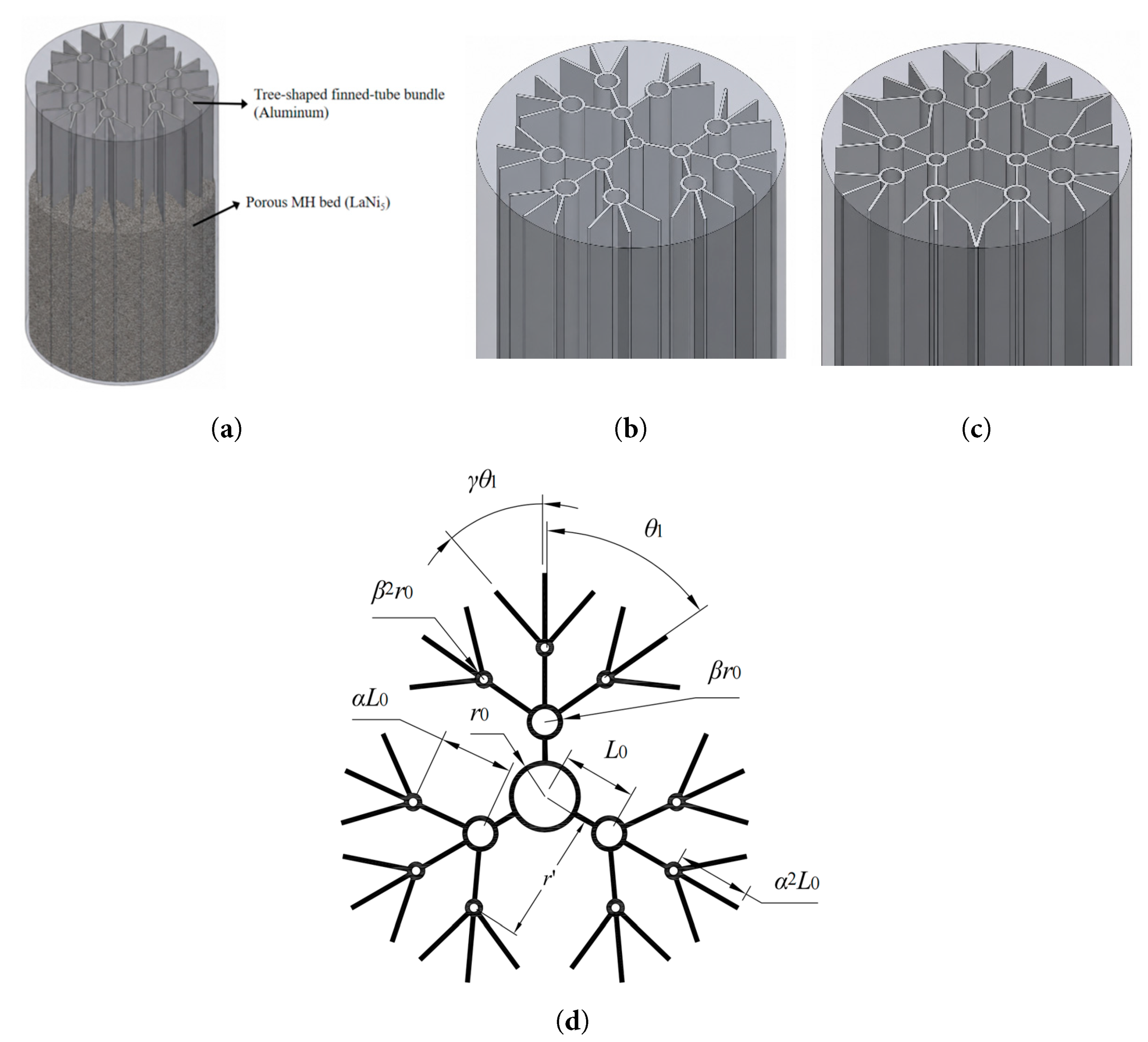
Figure 1: Geometric model and structural parameters of the reactor: (a) 3D reactor model showing the porous MH bed and aluminum heat-exchanger structure; (b) baseline tree-shaped finned-tube bundle; (c) configuration after reaction-dead-zone-oriented fin extension; and (d) definition of the geometric parameters.
Table 3: Model geometric dimension parameters.
| Parameters | Hidden Meaning | Unit Workplace |
|---|---|---|
| D | Reactor wall thickness | mm |
| L0 | Spacing between the primary and secondary heat exchanger tubes | mm |
| α | Common ratio for the variation in heat exchanger tube spacing: αL0 represents are the spacing between the secondary and tertiary heat exchanger tubes, and α2L0 denotes the distance from the axis of the tertiary tube to the outer side of its corresponding tertiary fin. | |
| r0 | Radius of the primary heat exchanger tube | mm |
| β | Common ratio for the variation in heat exchanger tube radius: βr0 and β2r0 are the radii of the secondary and tertiary heat exchanger tubes, respectively. | |
| θ | Secondary-fin included angle | ° |
| γ | Common ratio for the variation in fin included angle: γθ is the included angle of the tertiary fins. | |
| r′ | Radial distance from any point in the cylindrical reactor’s cross-section to the center | mm |
| δ | Distance from the outer edge of the fin to the point with the lowest reacted fraction within the reaction dead zone | mm |
2.5 Computational Methods and Model Validation
To reduce the computational cost while preserving the principal geometric characteristics of the proposed heat-transfer structure, a one-third sector of the reactor cross-section was selected based on the circumferential symmetry of the finned-tube bundle. The resulting computational domain was treated as a two-dimensional planar domain consisting of the porous LaNi5 bed, the aluminum heat-exchanger tubes and fins, the symmetry boundaries, and the external reactor wall. The HTF was not modeled as an explicit fluid domain; instead, its thermal effect was represented by a convective boundary condition imposed on the inner surfaces of the heat-exchanger tubes. The initial temperatures of both the LaNi5 bed and the HTF were set to 293.15 K. A convective heat-transfer coefficient of 2000 W·W/(m2·K) and an HTF bulk temperature of 293.15 K were prescribed at the tube-wall boundaries. The external reactor wall was treated as adiabatic, while symmetry conditions were imposed on the two radial boundaries. The LaNi5 bed was modeled as an isotropic porous medium with a porosity of 0.5 and an effective thermal conductivity of 2.4 W/(m·K).
The computational domain was discretized in ANSYS ICEM CFD using an unstructured, predominantly triangular mesh generated with the patch-dependent, quad-dominant meshing strategy. Local refinement was applied around the aluminum fins, heat-exchanger tube walls, narrow gaps, and geometric junctions, where relatively steep temperature gradients were expected. The mesh was gradually coarsened toward the outer region of the LaNi5 bed to reduce the computational cost. The adopted mesh contained 12,002 triangular elements and 5634 nodes. The maximum element sizes in the MH-bed and finned-tube regions were 3 mm and 0.12 mm, respectively. Five global smoothing iterations were performed with a target quality value of 0.20. The resulting element-quality values ranged from 0.461986 to 0.997534, with no elements below the prescribed threshold.
The governing equations were solved in ANSYS Fluent 2021 R1 using a transient pressure-based solver. Pressure–velocity coupling was handled using the SIMPLE algorithm, and spatial gradients were evaluated using the least-squares cell-based method. The pressure term was discretized using the second-order scheme, while the density, momentum, and energy equations were discretized using the second-order upwind scheme. A first-order implicit formulation was adopted for temporal discretization. Convergence at each time step was assessed using the absolute residuals of the continuity, x-velocity, y-velocity, and energy equations, with the convergence criterion set to 1 × 10⁻⁸ for all monitored equations.
Jemni et al. [24] experimentally examined the performance of a hydrogen storage reactor containing 422 g of LaNi5 and recorded the temperature variations at several specified positions inside the reactor. According to the results reported by Chung et al. [35], the effect of thermal convection in the MH bed can be reasonably neglected when the volume expansion of the metal bed is not taken into account. In the present study, the mathematical model is mainly employed to describe the temperature distribution in the bed and the dynamic evolution of the reacted fraction during hydrogen absorption. Since the bed expansion is not considered, the thermal convection term is omitted. In the validation process, the degree of saturation of the metal hydride alloy is evaluated using the volume-averaged reacted fraction, as defined in Eq. (15). In the field of metal hydride hydrogen storage, the absorption process is generally considered to have reached practical saturation when this reacted fraction attains a value of 0.9. Fig. 2 illustrates the validation of the proposed hydrogen storage model, including a comparison of the temperature-rise profile at test point A based on the experimental results of Jemni et al., as well as a comparison between the reacted fraction curve reported by Chung et al. and the numerical results obtained in this work. When the temperatures of the heat transfer fluid were 293 K and 313 K, the maximum deviation in system temperature was below 1.5%, while the maximum deviation in reacted fraction remained below 1%. These results demonstrate that the proposed mathematical model is capable of accurately capturing the evolution behavior and overall variation trends of both the temperature field and the reacted fraction within the reactor during the hydrogen storage process.
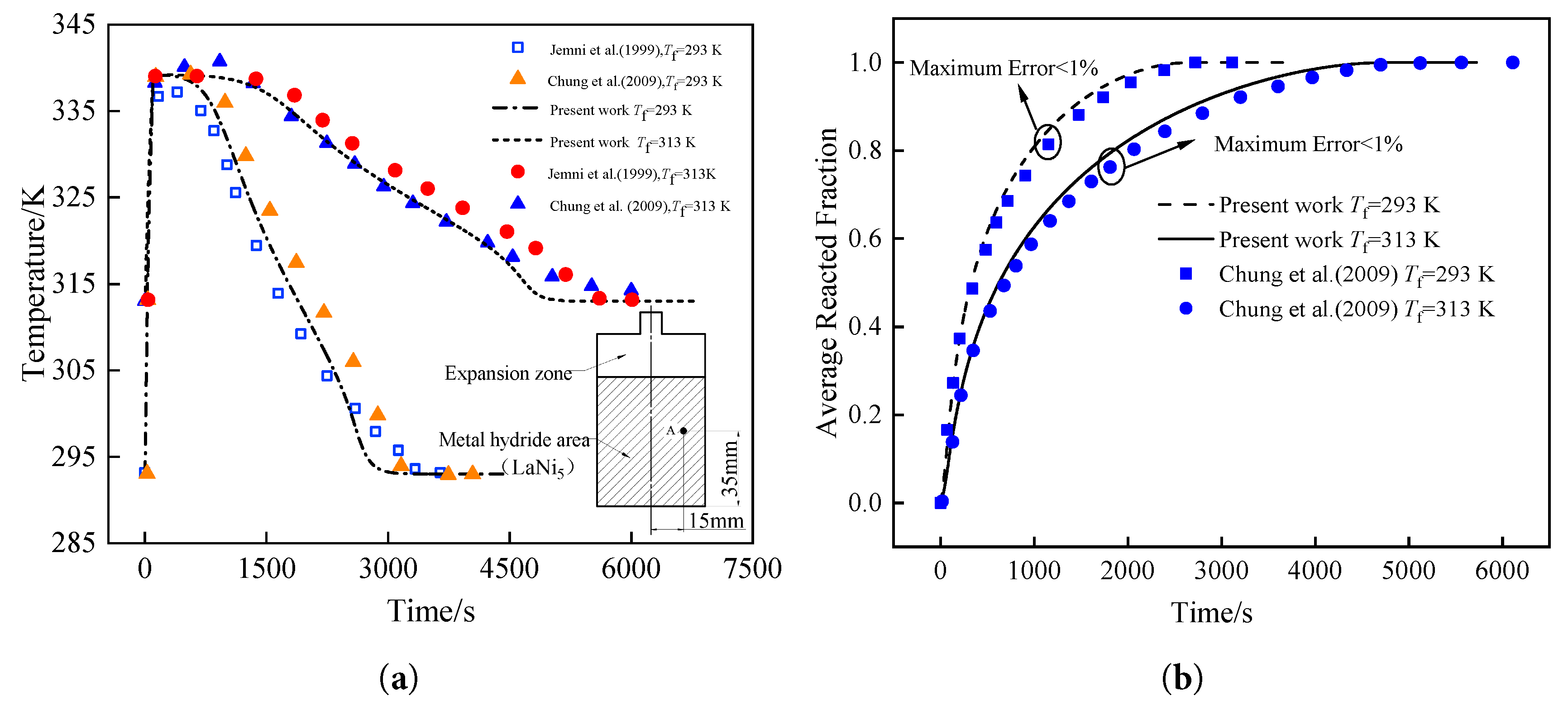
Figure 2: Model validation of the MH hydrogen storage reactor: (a) comparison between experimental and simulated local bed temperature evolutions at a representative point (r = 15 mm, z = 25 mm) under different heat transfer fluid temperatures; (b) comparison of reacted fraction evolutions under different heat transfer fluid temperatures.
The grid-independence test shown in Fig. 3 was conducted using the baseline secondary tree-shaped finned-tube configuration. The tertiary tree-shaped finned-tube bundle investigated in the subsequent sections was developed from this baseline geometry by adding a third hierarchical level of heat-exchanger tubes and fins. Both configurations employ the same governing equations, material properties, initial and boundary conditions, meshing criteria, and numerical schemes. Therefore, the mesh size and local refinement strategy determined from the secondary configuration were also applied to the subsequent tertiary configurations. The geometric dimensions and hierarchical relationships of the baseline and tertiary configurations are provided in Fig. 1 and Table 3.
The analysis was performed on an arbitrary radial section of the reactor. The computational domain included both the MH bed and the finned heat exchanger tube region. Unstructured triangular meshes were generated in ICEM. Owing to the central symmetry of the finned-tube bundle, a one-third geometrical model was employed for mesh discretization, as shown in Fig. 3a. The grid independence test shown in Fig. 3b reveals that when the number of mesh elements increased from 12,002 to 18,441, the relative error in the hydrogen absorption time, τ, corresponding to an average reacted fraction of 0.9, was less than 0.15%. Therefore, the mesh with 12,002 elements was adopted in the subsequent simulations. In this mesh system, the maximum element sizes in the MH bed region and the finned-tube region were 3 mm and 0.12 mm, respectively.
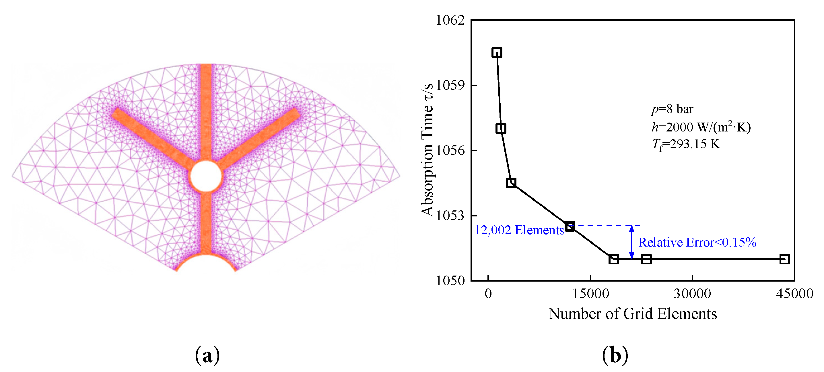
Figure 3: Computational mesh and grid-independence study for the baseline secondary tree-shaped finned-tube configuration: (a) computational mesh; and (b) grid-independence verification.
It should be clarified that the retained values of α, β, γ, θ, r0, and δ were obtained through sequential single- or paired-parameter CFD comparisons under the prescribed geometric and volume-fraction constraints, with the hydrogen absorption time τ used as the primary performance criterion. Therefore, the reported parameter combination represents the best-performing case among the investigated discrete configurations rather than a mathematically proven global optimum.
The geometric parameters investigated in this study—the tube spacing ratio (α), the tube radius ratio (β) with primary tube radius (r0), the secondary-fin included angle (θ) with fin angle ratio (γ), and the fin extension distance (δ)—follow directly from the structural definition of the tree-shaped finned-tube bundle rather than being arbitrarily chosen. The spacings, tube radii, and fin angles at successive hierarchical levels are prescribed by geometric progressions, with α, β, and γ serving as the common ratios for tube spacing, tube radius, and fin angle, respectively, all governed by the geometric constraint L0 + αL0 + α2L0 = 25 mm. The scanned ranges of each parameter are bounded by the volume fraction constraint φ ≤ 15%. The constructal theory framework established by Bejan [36] and extended to three-dimensional convective assemblies by Alebrahim and Bejan [37] provides the theoretical backdrop for this hierarchical parameterization, demonstrating that optimal tree-like heat transfer geometries emerge from the minimization of thermal resistance subject to volume constraints. A closed-form analytical solution of this type is not available for the present system owing to the coupled reaction kinetics, porous-media flow, and conjugate heat transfer involved; the parameter study is therefore conducted numerically.
Numerical simulations were conducted under a constant hydrogen storage pressure of p = 8 bar, a heat transfer fluid temperature of Tf = 293.15 K, and a convective heat transfer coefficient of h = 2000 W/(m2·K). Two-dimensional schematics of the MH hydrogen storage reactors with different heat exchanger configurations are presented in Fig. 4, including secondary tree-shaped finned-tube bundles, tertiary tree-shaped finned-tube bundles, conventional tube bundles, and single finned tubes. The volume fraction for all four configurations was maintained at 12.36%, with the tube bundle distribution identical to that of the tertiary tree-shaped configuration. The temporal evolution of the reacted fraction for these reactors is shown in Fig. 4e. The results indicate that the tertiary tree-shaped finned-tube bundle exhibits superior performance, with a hydrogen absorption time of 490 s. Compared to the conventional tube bundle, single finned tube, and secondary tree-shaped bundle, the absorption time was reduced by 35.44%, 41.03%, and 54.44%, respectively, significantly enhancing the reactor’s performance. The initial geometric parameters for this baseline configuration are: L0 = 8.33 mm, αL0 = 8.33 mm, α2L0 = 8.34 mm, r0 = 4 mm, βr0 = 2 mm, β2r0 = 1 mm, θ = 55°, and γθ = 41°. Therefore, further parametric comparison focusing on the geometric parameters of the tertiary tree-shaped finned-tube bundle (Fig. 4b) is essential. The superior performance of the tertiary tree-shaped finned-tube bundle may be attributed to its more effective coordination between heat transfer path reduction and spatial distribution of cooling capacity. In the conventional tube bundle, although multiple heat exchanger tubes are introduced, the absence of extended fins limits the penetration of the high-conductivity structure into the surrounding MH region. In the single finned-tube configuration, the enhancement effect is mainly concentrated near the reactor center, whereas the peripheral region remains subject to substantial heat accumulation. By comparison, the tertiary tree-shaped configuration integrates distributed heat exchanger tubes with hierarchical fins, thereby extending the high-conductivity network deeper into the MH bed. This structural feature reduces the effective conduction distance over a wider domain and contributes to a more uniform temperature field, which is favorable for maintaining hydrogen absorption in regions that would otherwise evolve into reaction dead zone.
The present study conducts a comparative CFD-based assessment of a series of discrete tree-shaped finned-tube geometries. The investigated geometric variables are the tube-spacing ratio α, the primary-tube radius r0, the tube-radius ratio β, the secondary-fin included angle θ, the fin-angle ratio γ, and the fin-extension distance δ. The investigated configurations satisfy a heat-exchanger structure volume fraction of φ ≤ 15%, the geometric relation L0 + αL0 + α2L0 = 25 mm, and fixed fin and tube-wall thicknesses of 0.5 mm. Each configuration is evaluated using the hydrogen absorption time, the volume-averaged reacted fraction, the average bed temperature, and the spatial extent of the reaction dead zone. The parameter values retained for subsequent comparisons correspond to the best-performing cases within the discrete ranges examined; they should not be interpreted as a mathematically proven global optimum over the complete multidimensional design space. To minimize the variation in the MH mass during optimization, this study explores the influence of fin length, tube radius, and fin angles at each stage on the hydrogen absorption time for the tertiary tree-shaped configuration, while constraining the volume fraction of the heat exchanger structure to below 15%. The objective is to minimize the hydrogen absorption time τ, with reaction dead-zone mitigation serving as the governing physical mechanism rather than a separate objective function.
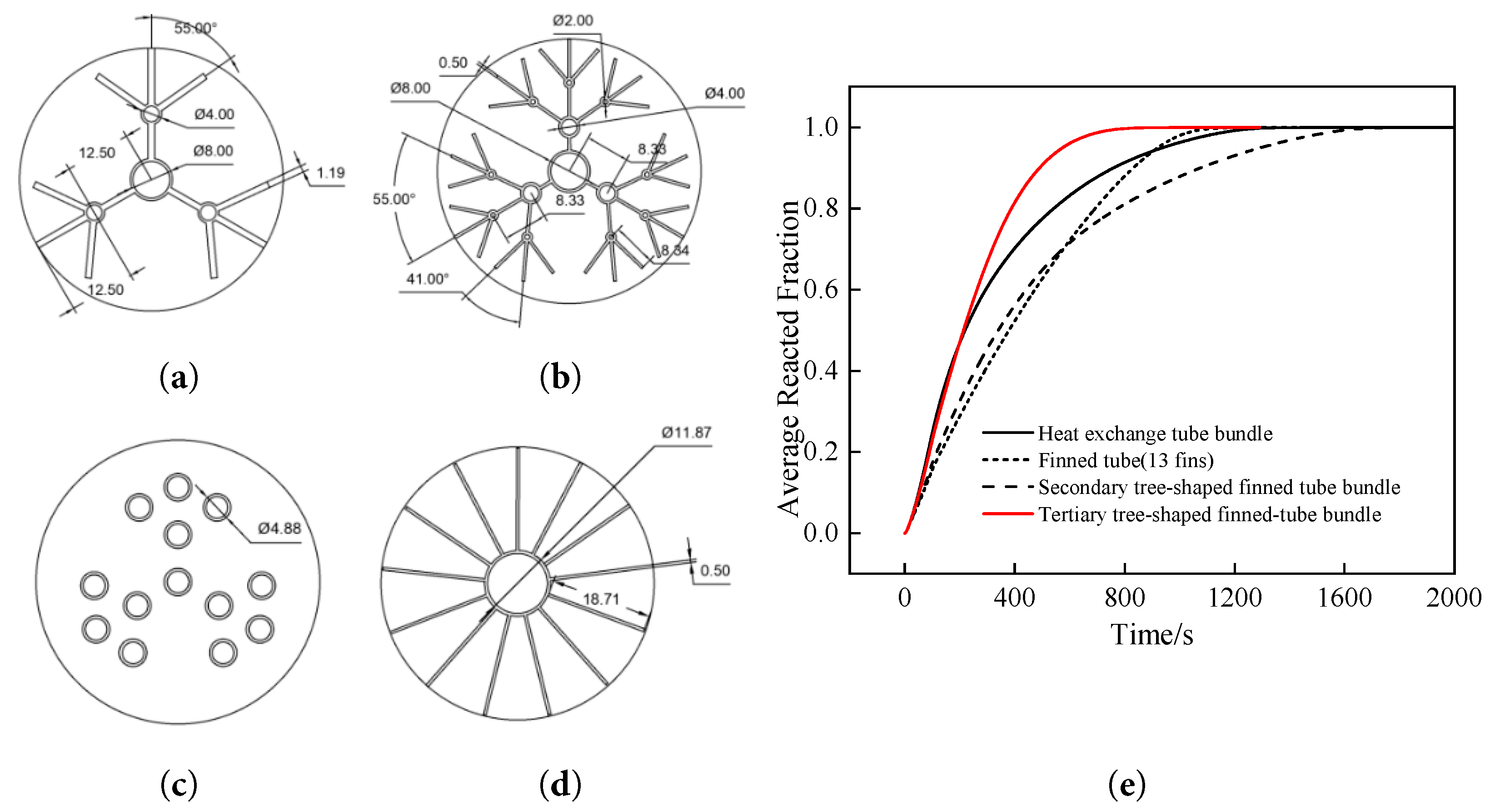
Figure 4: Comparison of various heat exchanger configurations and their hydrogen absorption kinetics: (a) secondary tree-shaped finned-tube bundle; (b) tertiary tree-shaped finned-tube bundle; (c) heat exchanger tube bundle; (d) individual finned tube; (e) profiles of average reacted fraction versus time.
3.1 Effect of Heat Exchanger Tube Spacing Common Ratio on Hydrogen Storage Performance
The temporal evolution of the average bed temperature and reacted fraction under various geometric ratios α is illustrated in Fig. 5. During the initial heating stage (0–100 s), the differences in temperature distribution among different α values are relatively minor. This is because the reaction driving force is primarily governed by the differential between the actual hydrogen pressure and the equilibrium pressure corresponding to the bed temperature. As the reaction proceeds into the cooling stage (t ≥ 100 s), the initial average bed temperature increases with α, though the slope of the temperature curve becomes steeper. In the later stages of the reaction, the average temperature decreases as α increases. This phenomenon is attributed to the fact that a smaller α leads to a higher concentration of fins and tubes near the reactor axis, resulting in a lower average temperature early on. Conversely, as α increases, the length of the primary fins decreases while the lengths of the secondary and tertiary fins increase, thereby enhancing the uniformity of the heat exchanger distribution within the bed. This increased uniformity reduces the thermal conduction distance from the MH to the heat exchanger tubes, allowing the reaction heat to be dissipated more rapidly to the HTF, which accelerates the temperature drop and enhances the hydrogen absorption rate in the later stages.
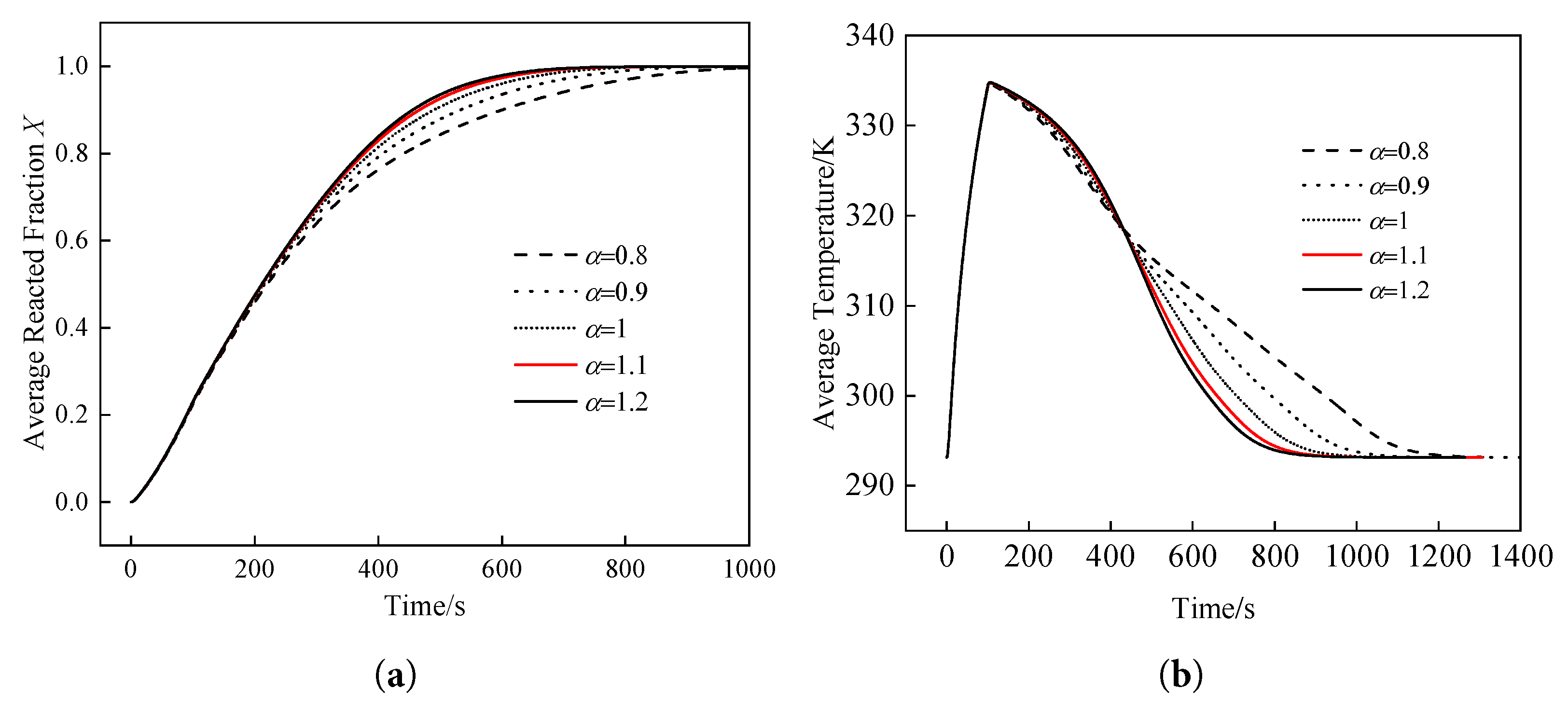
Figure 5: Effects of heat exchanger tube spacings on the hydrogen absorption performance: (a) evolution of average reacted fraction; (b) evolution of average bed temperature.
Fig. 6 presents the contour plots of the temperature and reacted fraction distributions within the hydrogen storage reactor at t = 500 s for different α values. As α increases, the areas of high-temperature regions and incomplete reaction zones (i.e., reaction dead zone) gradually diminish, and the temperature distribution becomes more uniform. At lower α values, extensive high-temperature reaction dead zone persist near the reactor wall and the symmetry boundaries, while the temperatures of the finned-tube bundles and the adjacent MH are significantly lower, with the hydrogen storage nearing saturation. As α increases, the temperature in the vicinity of the heat exchanger tubes rises slightly but remains below approximately 311.4 K, while the extent of the high-temperature regions on both sides is markedly reduced. For instance, at α = 0.8, the reaction dead zone temperature exceeds 334.4 K with a reacted fraction below 0.3. In contrast, at α = 1.2, the bed temperature near the symmetry boundary significantly drops to 316–325.2 K, the reacted fraction consistently exceeds 0.6, and the overall area of the reaction dead zone near the wall is substantially contracted.
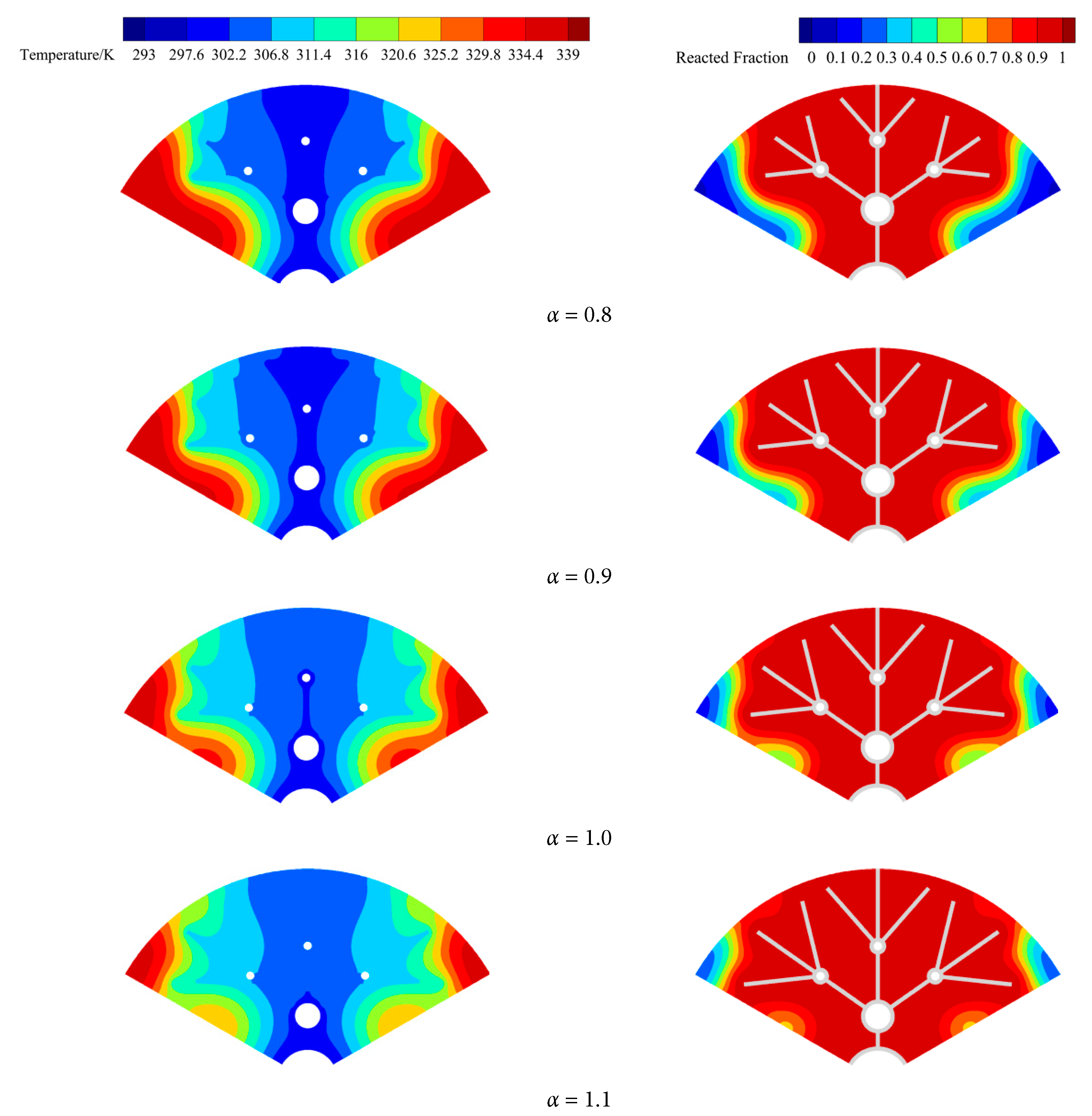
Figure 6: Temperature and reacted fraction distribution contour plots in the hydrogen storage reactor at 500 s with different heat exchanger tube spacing ratios.
Fig. 7 illustrates the variation of the fin volume fraction as a function of the geometric ratio α for the tube spacing. As α increases from 0.8 to 1.1, the fin volume fraction rises from 11.26% to 12.85% accordingly. For α values of 0.8, 0.9, 1.0, 1.1, and 1.2, the corresponding hydrogen absorption times are 600.0 s, 532.5 s, 490.0 s, 466.0 s, and 455.5 s, respectively, exhibiting a consistent downward trend as α increases. Compared to the case with α = 0.8, the configuration with α = 1.1 results in a significant 22.33% reduction in hydrogen absorption time, while the volume fraction increases by only 1.59%. Further increasing α from 1.1 to 1.2 yields an additional, but comparatively marginal, 2.31% reduction in absorption time. It should be noted that τ decreases monotonically with α over the entire tested range (0.8–1.2), and α = 1.2 in fact yields the lowest absorption time (455.5 s) among all sampled values; α = 1.1 is therefore not a true extremum of τ within this range, but rather the point beyond which the marginal benefit of further increasing α diminishes substantially—α = 1.1 alone captures 92.7% of the total reduction achieved between α = 0.8 and α = 1.2. Given this pronounced diminishing return, together with the increased structural complexity of further narrowing the tertiary fin and tube dimensions at higher α, α = 1.1 is adopted as the working value for subsequent sections rather than the value that strictly minimizes τ within the tested range.
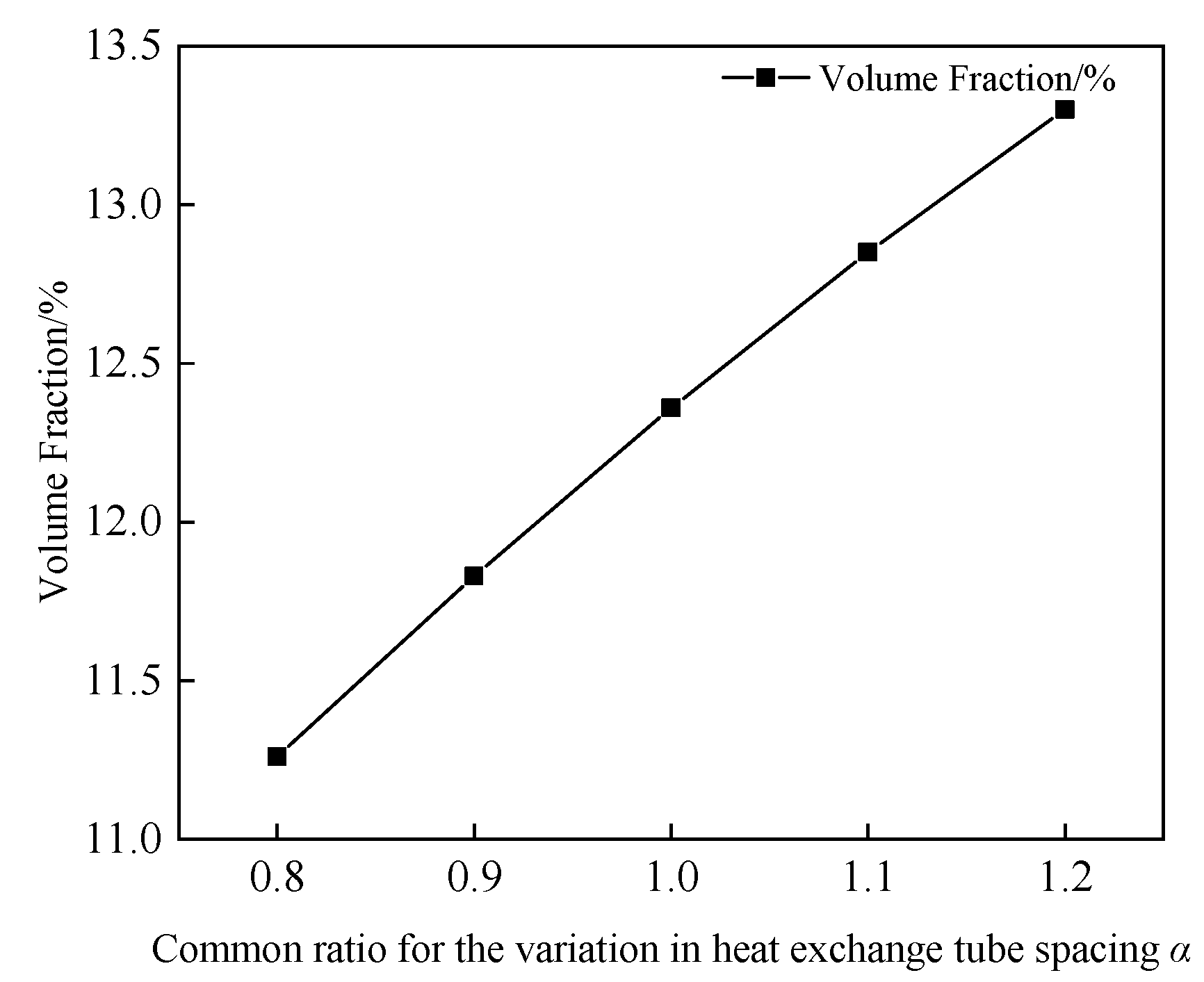
Figure 7: Fin volume fraction versus common ratio α for different heat exchanger tube spacings.
3.2 Effect of Heat Exchanger Tube Radius on Hydrogen Storage Performance
It should be noted that the number of investigated β values varies with r0 because all geometric configurations were required to satisfy the prescribed heat-exchanger structure volume-fraction constraint of φ ≤ 15%. For relatively large primary-tube radii, a further increase in β rapidly increases the volumes of the secondary and tertiary tubes, causing some geometric combinations to exceed the allowable volume fraction. These infeasible cases were therefore excluded before the CFD calculations, resulting in fewer data points for some values of r0.
Fig. 8 illustrates the variation of the hydrogen absorption time as a function of the tube radius ratio β under different primary tube radii r0. Generally, the hydrogen absorption time exhibits a downward trend as the value of β increases. This is attributed to the fact that, when the primary tube radius remains constant, an increase in the ratio β leads to larger radii for the secondary and tertiary tubes. Consequently, the heat transfer capacity of the finned-tube bundle is enhanced, which accelerates the absorption kinetics and reduces the overall absorption time. In contrast, increasing r0 results in a significant extension of the hydrogen absorption time. This occurs because, under the volume fraction constraint imposed in this study, an increase in r0 necessitates a reduction in the radius of the tertiary tubes. Furthermore, the mass of the MH in the regions surrounding the tertiary tubes is substantially higher than that near the primary and secondary tubes. This imbalance weakens the localized cooling effect of the finned-tube bundle. Therefore, a larger r0 would require even larger tube radii to effectively strengthen the thermal dissipation performance of the finned-tube bundle.
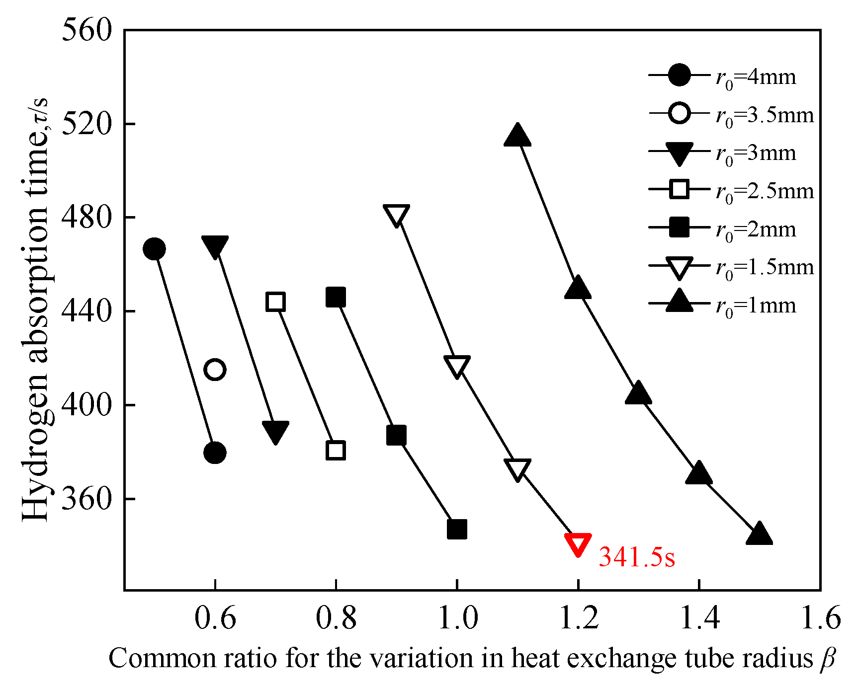
Figure 8: Hydrogen absorption time versus radius ratio β for different primary tube radii.
When β increases by an increment of 0.1, the magnitude of the reduction in hydrogen absorption time varies across different primary tube radii (r0). For instance, at r0 = 4 mm, increasing β from 0.5 to 0.6 reduces the absorption time by 87 s; however, at r0 = 1 mm, increasing β from 1.1 to 1.2 results in a reduction of only 65 s. This suggests that as the primary tube radius decreases, the incremental change in the heat exchanger tube volume per 0.1 increase in β diminishes, thereby reducing the sensitivity of the hydrogen absorption rate to the tube radius ratio.
Fig. 9 illustrates the variation of the tree-shaped fin volume fraction as a function of the tube radius ratio β for various r0 values. For r0 = 2.5, 3, and 3.5 mm, the volume fraction rises significantly with β, exceeding the 15% threshold at higher β values. This is attributed to the fact that the secondary and tertiary tubes, which are more numerous, are predominantly distributed toward the periphery of the reactor. As β grows, the radii of these tubes increase significantly, leading to a rapid surge in the total volume fraction. Furthermore, the volume fraction trends upward with β across all r0 values, as a higher β directly increases the volume of the secondary and tertiary tubes. Notably, for cases where r0 = 1, 1.5, 2, and 4 mm, the volume fractions are similar at their respective optimal β values, yet the resulting hydrogen absorption times exhibit substantial differences.
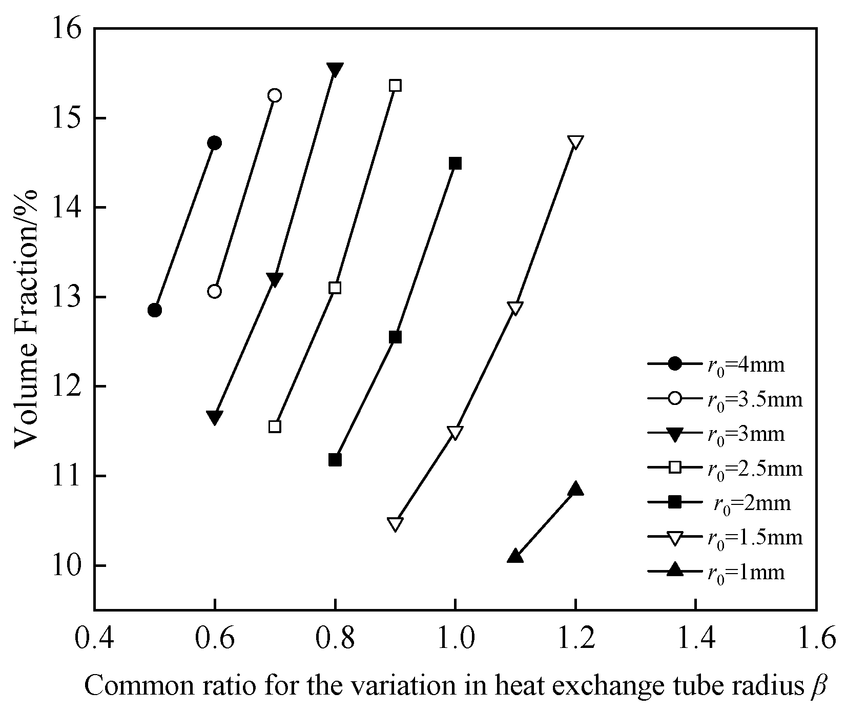
Figure 9: Tree-shaped fin volume fraction versus radius ratio β for different primary tube radii.
Fig. 10 presents the contour plots of the temperature and reacted fraction distributions within the reactor at 300 s under optimal β values for different primary tube radii, r0. Using the best-performing β value for each r0 significantly impact the internal temperature field and reacted fraction. As shown in Fig. 10a, the high-temperature regions gradually expand with an increase in r0. When r0 = 1.5 mm, the internal temperature ranges from 298 K to 306.8 K. However, as r0 increases to 2.5 mm and 3.5 mm, the area of the high-temperature region grows, the average bed temperature rises, and the extent of the reaction dead zone correspondingly expands.
Fig. 10b illustrates the reacted fraction distributions at 300 s for various r0 values. As r0 increases, the regions with a high reacted fraction diminish significantly. For r0 = 1.5 mm, the reaction is more complete across a larger area, resulting in the shortest hydrogen absorption time of 341.5 s. Conversely, as r0 increases to 2.5 mm and 3.5 mm, the reacted fraction drops, and the area of incomplete reaction dead zone increases markedly. This occurs because, in a cylindrical reactor, the mass of the MH increases with radial distance, necessitating a larger tube diameter to reinforce the cooling effect of the finned-tube bundle. A smaller primary tube radius allows for a broader adjustment range for β while maintaining a low volume fraction. However, if the primary tube radius is excessively small, achieving high performance requires a significantly larger β, which inevitably leads to an unacceptable surge in the volume fraction. The combined influence of r0 and β reflects the competition between local heat removal enhancement and the overall allocation of high-conductivity material within the reactor. An increase in β enlarges the secondary and tertiary heat exchanger tubes, thereby strengthening the cooling capacity in the outer MH region, where the local conduction path is longer and the surrounding MH inventory is larger. This contributes to suppressing peripheral heat accumulation and restricting the expansion of reaction dead zone. In contrast, an excessive increase in r0 under a constrained volume fraction leads to an over-allocation of heat exchanger volume to the central region, while limiting the dimensions of the outer branches. Since the outer region is more prone to thermal accumulation, such a redistribution is detrimental to the global hydrogen absorption performance. Therefore, the optimal tube radius design is governed not by the maximization of an individual tube size, but by the appropriate radial allocation of heat exchanger capacity across different hierarchical levels.
Among the discrete combinations examined, the configuration with r0 = 1.5 mm and β = 1.2 exhibits the shortest hydrogen absorption time of 341.5 s while satisfying the prescribed volume-fraction constraint. This combination is therefore retained as the reference geometry for the subsequent comparisons.
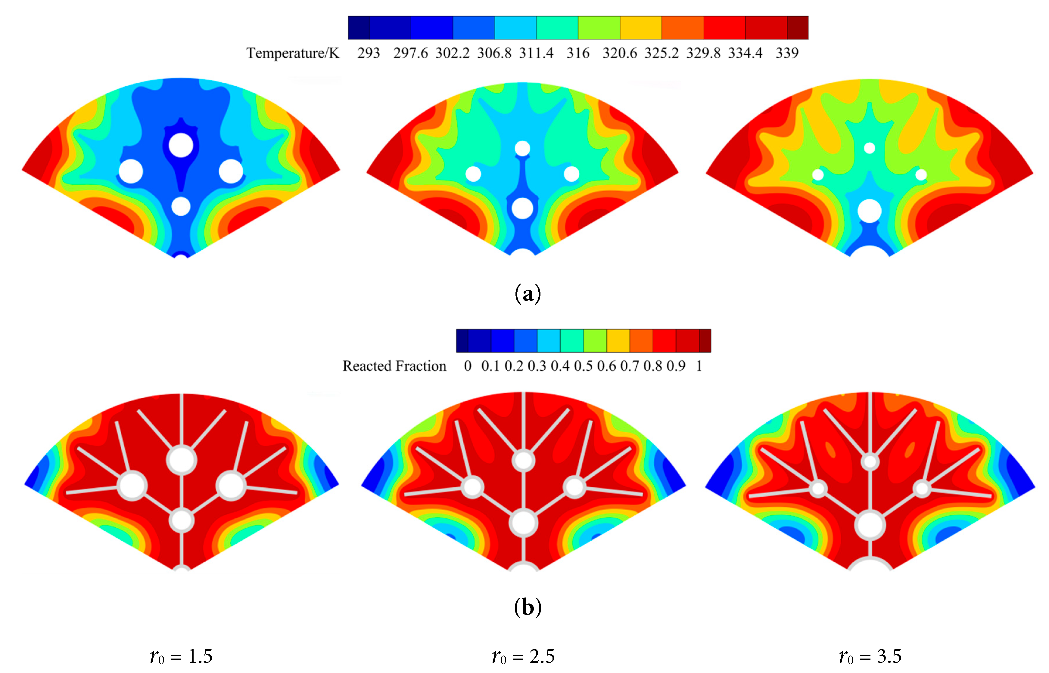
Figure 10: Contour plots of temperature and reacted fraction distributions at t = 300 s under different primary tube radii (r0) with optimal β. (a) Temperature distribution; (b) reacted fraction distribution.
3.3 Effect of Secondary-Fin Included Angle on Hydrogen Storage Performance
This section investigates four different secondary-fin included angles, specifically θ = 50°, 55°, 60°, and 65°, to determine the optimal fin angle ratio, γ, and its influence on the absorption time. Since only the angles are modified, the volume fraction of the heat exchanger remains constant in this section.
The hydrogen absorption times under various γ values are presented in Fig. 11. The simulation results indicate that for secondary-fin included angles of 50°, 55°, 60°, and 65°, the shortest absorption times are achieved when γ is 0.9, 0.7, 0.6, and 0.7, respectively.
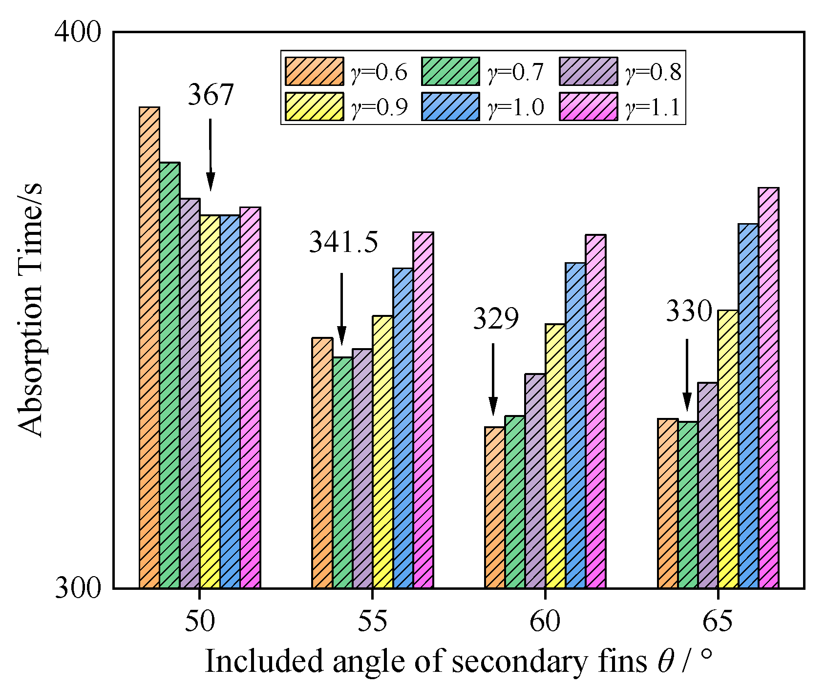
Figure 11: Hydrogen absorption time under different secondary-fin included angles θ and fin-angle ratios γ.
For θ = 50°, the absorption time initially decreases to 367 s when γ = 0.9 and then gradually increases as γ rises. A similar trend is observed for θ = 55°, where the minimum time is 341.5 s at γ = 0.7. For θ = 60°, the absorption time increases with γ, achieving a minimum of 329 s at γ = 0.6. When θ = 65°, the shortest time is 330 s at γ = 0.7. The variations in θ and γ dictate the spatial uniformity of the fins and tubes within the bed; under otherwise identical conditions, a more uniform distribution yields a faster hydrogen absorption rate.
Fig. 12 displays the temperature and reacted fraction contours at 300 s for the optimal configuration where θ = 60°, γ = 0.6, r0 = 1.5 mm, and β = 1.2. Prior to angle-parameter comparison with θ = 55°, the bed temperature near the heat exchanger tubes was maintained at approximately 315 K, the area with a reacted fraction near 1 was restricted, and distinct, large reaction dead zone persisted at the reactor periphery. Following angle-parameter comparison with θ = 60°, the temperature in most regions near the tubes drops to approximately 300 K, the highly reacted area expands significantly, and the reaction dead zone area is noticeably reduced.
The configuration with θ = 60° and γ = 0.6 yields the shortest absorption time and is thus selected for further study. Compared to the pre-optimization state, the absorption time is reduced from 341.5 s to 329 s without altering the volume fraction. Compared to the baseline before radius and angle-parameter comparison, the absorption time is reduced by 29.4% with only a marginal 1.9% increase in volume fraction.
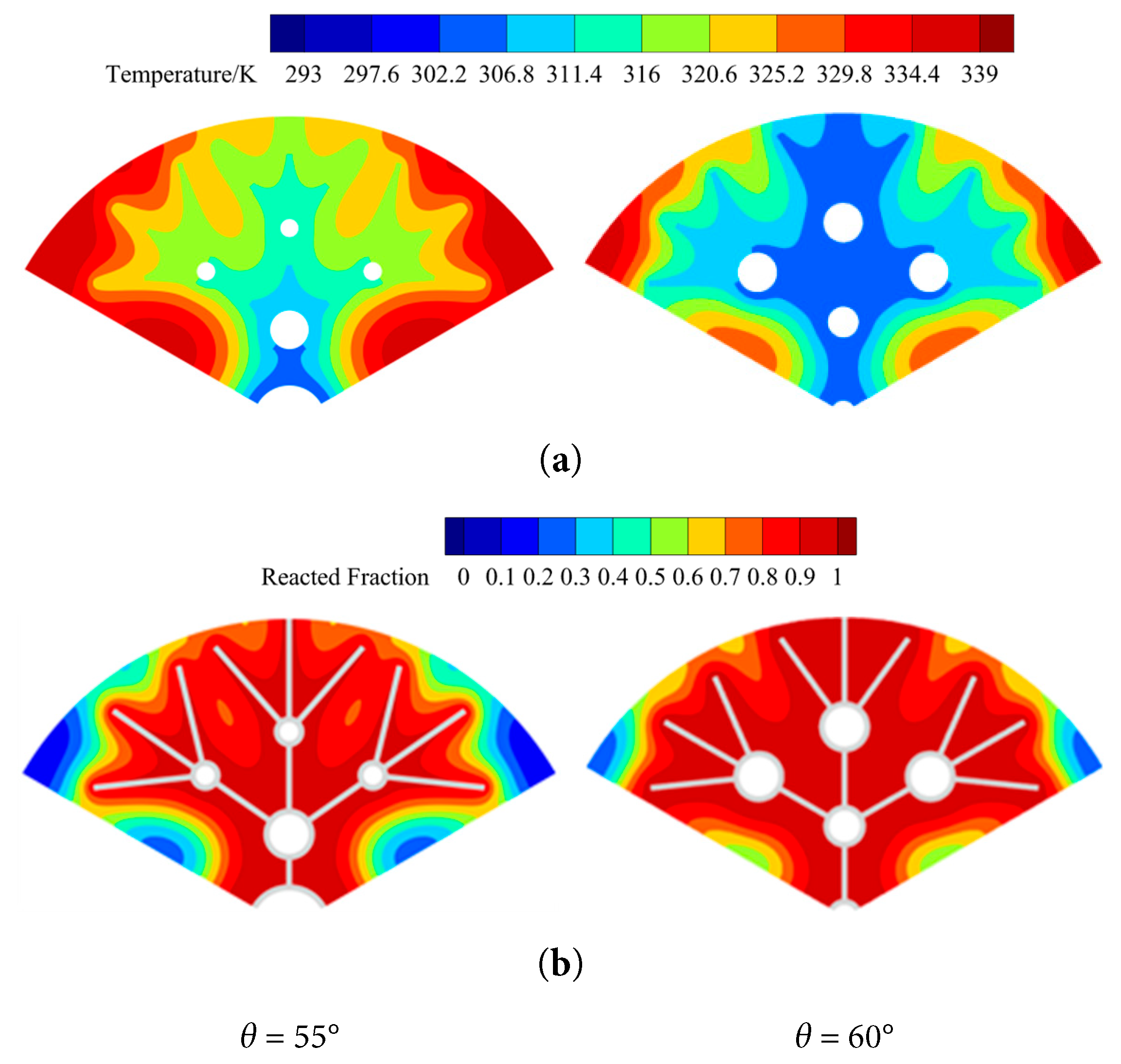
Figure 12: Contour plots of physical fields at t = 300 s under conditions of γ = 0.6, r0 = 1.5 mm, and β = 1.2 for different θ: (a) temperature distribution; (b) reacted fraction distribution.
3.4 Comparative Assessment of Fin Extensions toward Reaction Dead Zone
The temporal evolution of the temperature and reacted fraction distributions for the optimized reactor is shown in Fig. 13. After the geometric modification, the bed temperature stabilizes around 310 K, and the regions achieving a reacted fraction between 0.9 and 1 are substantially enlarged, demonstrating excellent cooling and heat transfer efficacy. Nevertheless, sluggish reaction dead zone still persist at the reactor periphery. To eliminate these zones, this study proposes extending specific fins into these regions and investigates the effect of the extended fin length on performance.
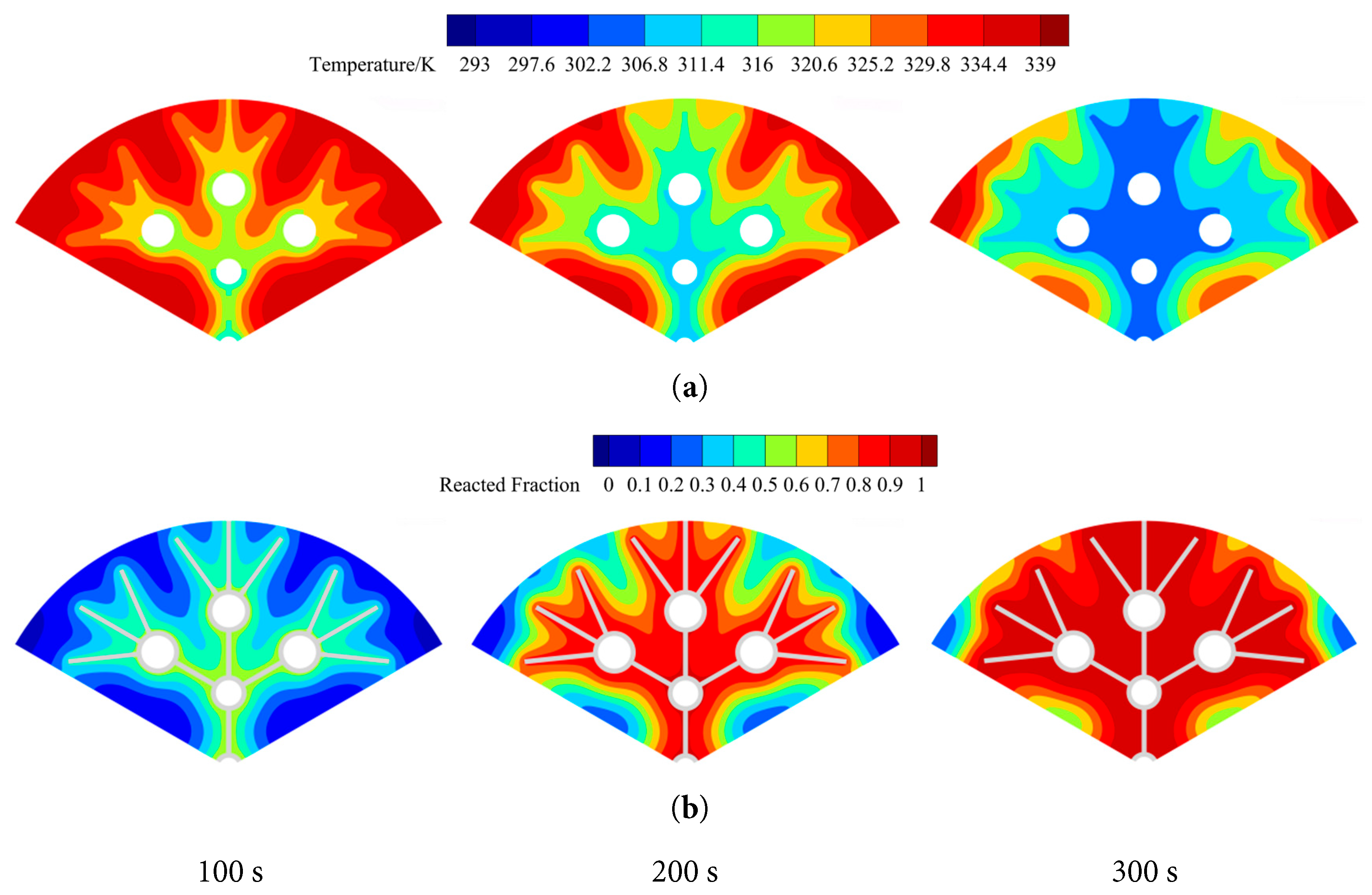
Figure 13: Contour plots of physical fields in the optimized dendritic finned-tube bundle reactor at t = 100, 200, and 300 s: (a) temperature distribution; (b) reacted fraction distribution.
Fig. 14 presents the reacted-fraction distribution extracted along a fixed sampling line near the outer reactor wall in the global Cartesian x-direction. The sampling line is parallel to the x-axis, with x = 0 corresponding to the reactor axis; positive and negative x-values denote positions on the two sides of the reactor axis. Several local minima are observed in the profile, corresponding to reaction dead zones with relatively slow hydrogen absorption and an adverse effect on the overall absorption performance. These reaction dead zones are mainly located near x = ±24.14, ±20.92, ±20.69, and ±9.88. To shorten the heat-conduction paths between these regions and the high-conductivity structure while minimizing the additional fin volume, fins are extended from the nearest existing fins or heat-exchanger tubes toward the corresponding locations.
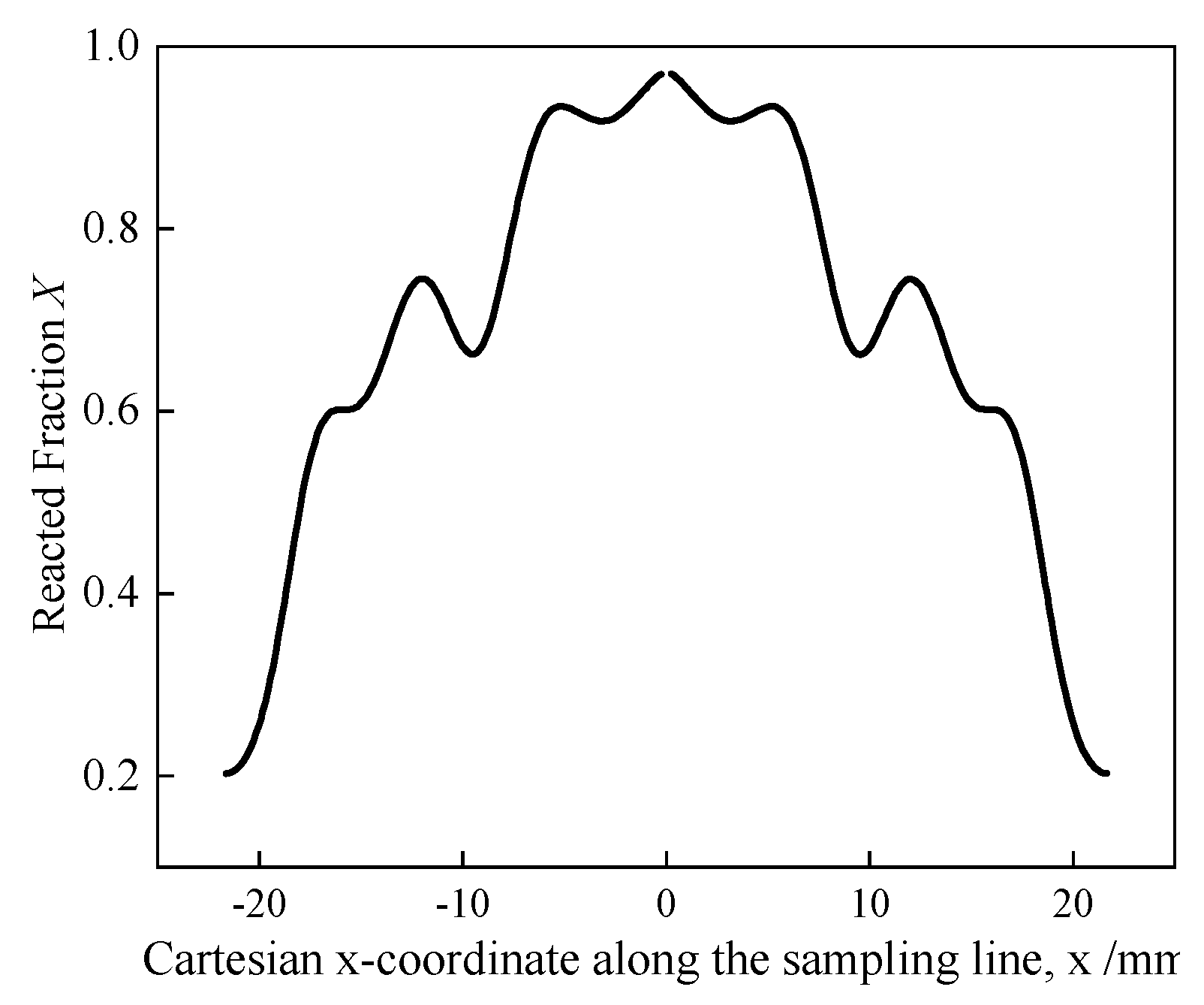
Figure 14: Reacted-fraction distribution along a fixed sampling line parallel to the global cartesian x-axis near the outer reactor wall.
Similarly, Fig. 15 shows the radial variation of the reacted fraction at the symmetry boundary. A distinct reaction dead zone is evident at r′ = 9.5 mm, which detracts from overall efficiency. Consequently, an extended fin is introduced here using the same approach.
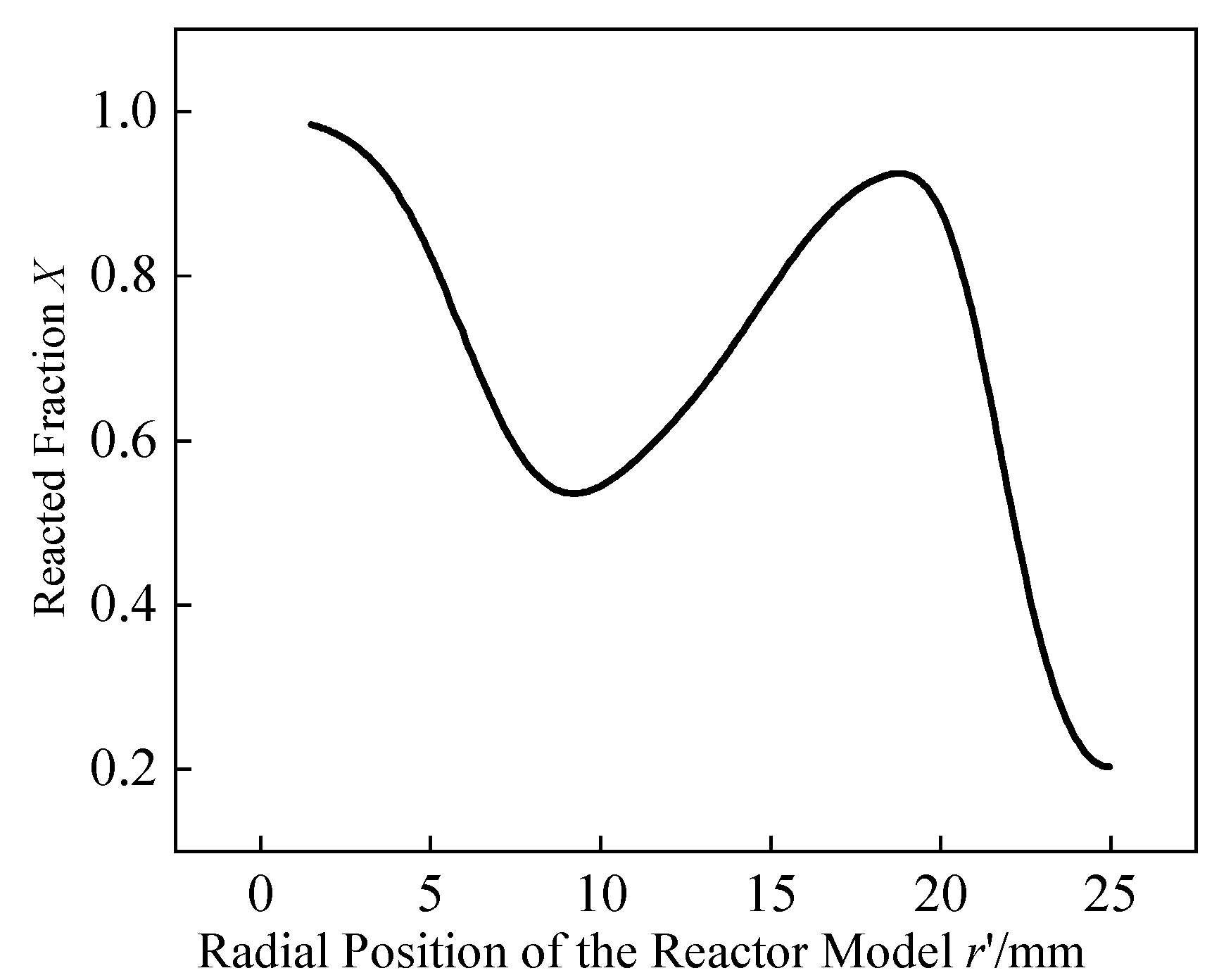
Figure 15: Radial profiles of reacted fraction at the symmetry boundary of the reactor.
Fig. 16 presents the temporal variation of the reacted fraction for different distances δ, between the extended fin tip and the reaction dead zone center. For δ = 0, 1, 2, and 3 mm, the absorption times are 284.0 s, 287.5 s, 294.0 s, and 306.5 s, respectively. Compared to configurations with δ = 2 mm and δ = 3 mm, the setup with δ = 1 mm reduces the absorption time by 2.21% and 6.19%. This demonstrates that extending fins into reaction dead zone effectively curtails absorption time. This behavior can be interpreted in terms of local thermal resistance regulation. In the reaction dead zone, the heat released by hydrogen absorption cannot be transferred efficiently to the heat exchanger structure, leading to persistent local temperature elevation, a corresponding increase in equilibrium pressure, and a reduction in the reaction driving force. By extending the fins toward these low-reacted-fraction regions, the local conduction path is shortened and the heat accumulated in the surrounding MH can be removed more effectively, thereby restoring hydrogen absorption activity in these thermally disadvantaged regions. It is also noted that the fin tip does not need to coincide exactly with the point of minimum reacted fraction. When δ is reduced to 1 mm, the dominant high-temperature region can already be effectively intercepted, whereas a further decrease in δ yields only a marginal reduction in hydrogen absorption time while introducing additional occupation of the MH region. This accounts for the existence of an optimal value at δ = 1 mm. When δ < 1 mm, further reduction in δ yields negligible performance gains. Therefore, δ = 1 mm represents the preferred trade-off among the investigated values. Compared to the reactor before reaction-dead-zone-oriented fin extension, the absorption time is shortened by 12.77%, at the cost of a mere 2.36% increase in volume fraction.
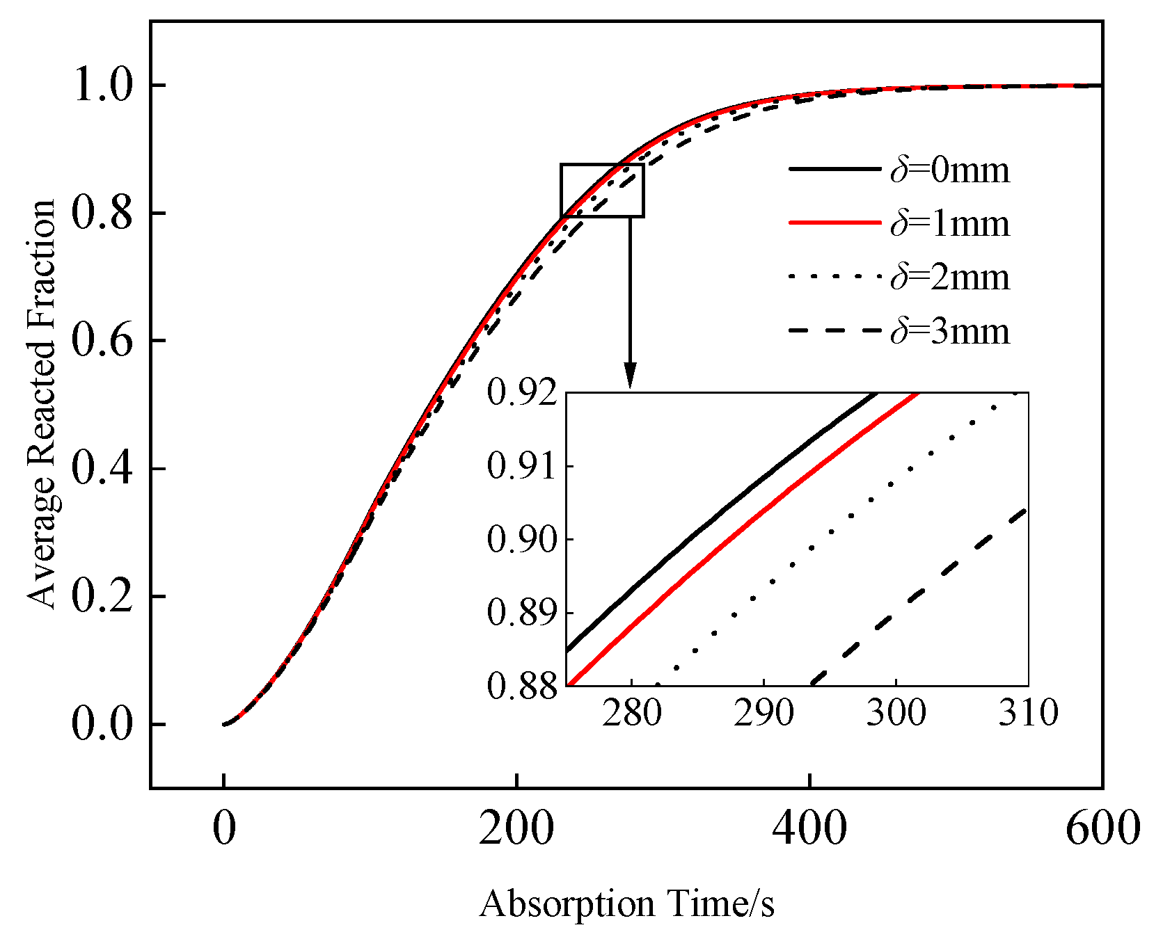
Figure 16: Evolution of average reacted fraction versus time for different distances between the fin tips and the reaction dead zone.
The temperature and reacted fraction contours at 300 s for δ = 1 mm are shown in Fig. 17. The internal temperature distribution becomes highly uniform, the high-temperature regions shrink significantly, and the majority of the bed cools to between 297.6 K and 320.6 K. Simultaneously, regions with a reacted fraction between 0.9 and 1 dominate the bed, confirming that extended fins successfully enhance heat transfer, promote complete reactions, and neutralize the impact of reaction dead zone.
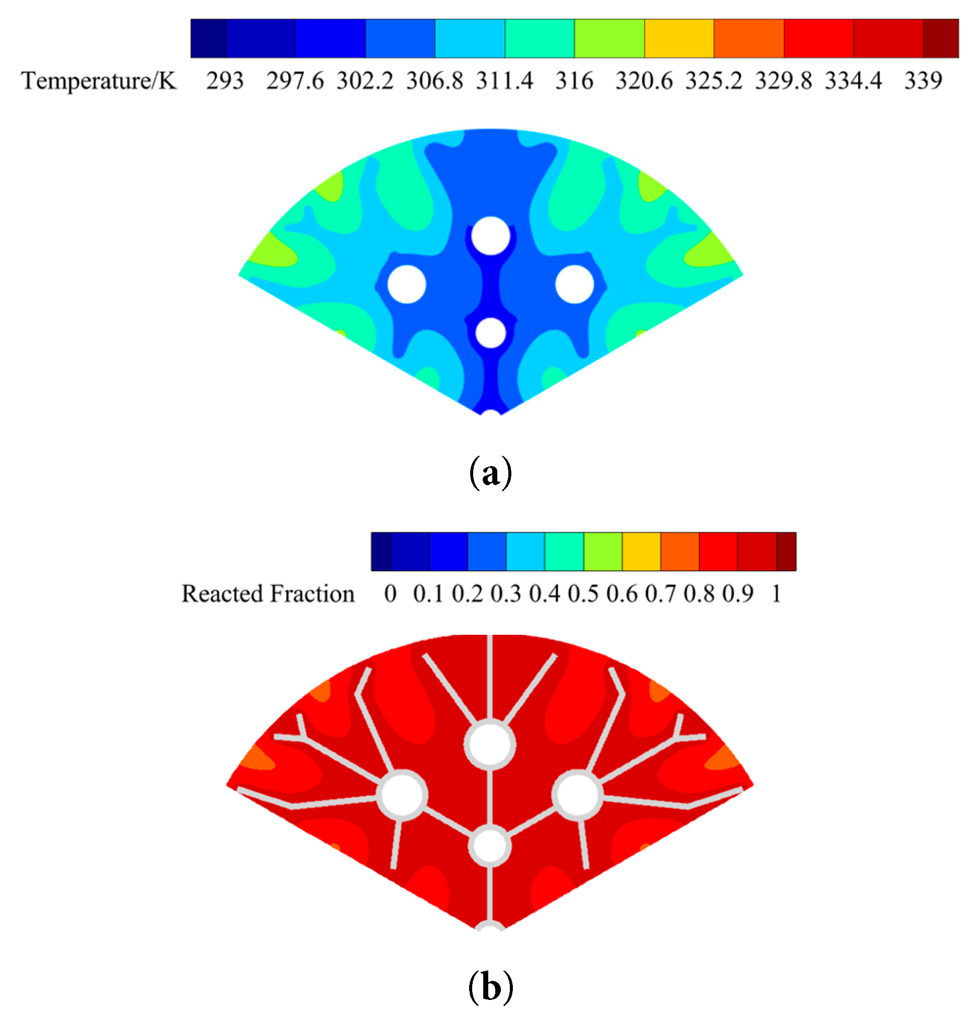
Figure 17: Contour plots of physical fields at t = 300 s with δ = 1 mm: (a) temperature distribution; (b) reacted fraction distribution.
Consequently, the reactor exhibits superior hydrogen storage performance when δ = 1 mm. Compared to the configuration before reaction-dead-zone-oriented fin extension, the hydrogen absorption time is reduced by 12.77%, while the volume fraction increases by only 2.36%.
In a prior study [18], genetic algorithm optimization of a tree-shaped finned-tube reactor with a volume fraction of 10%, a convective heat transfer coefficient of 1500 W/(m2·K), a hydrogen storage pressure of 8 bar, and an HTF temperature of 293 K resulted in 1620 s to reach an average temperature of 300 K, and a total absorption time of 1180 s. In contrast, as shown in Fig. 18, the optimized reactor in the present study reduces these times by 1203 s and 865.5 s, respectively, with only a 9.01% increase in volume fraction.
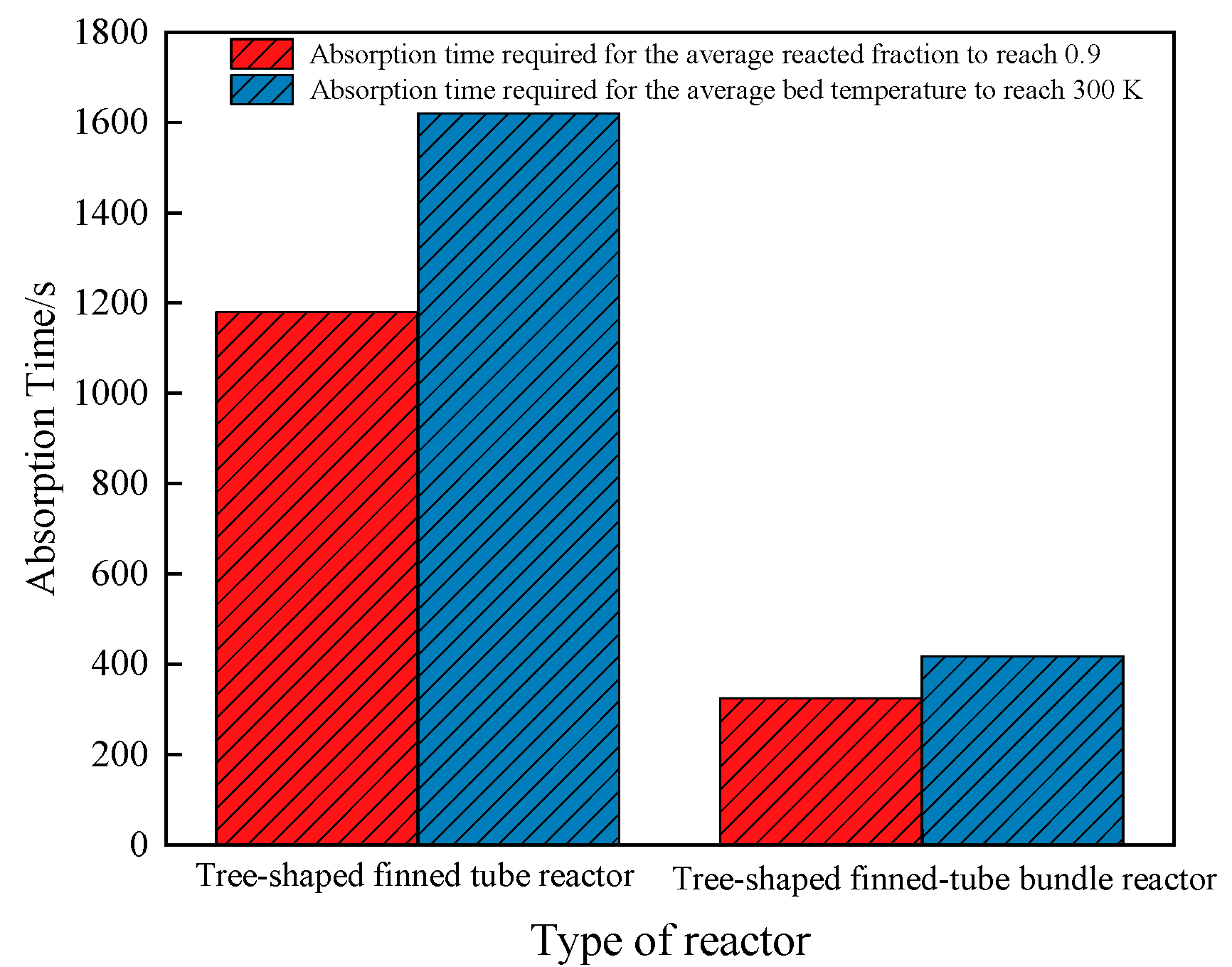
Figure 18: Comparison of hydrogen absorption time and the time to reach an average bed temperature of 300 K for different reactor configurations.
It should be noted that the sequential CFD-based parametric comparison presented in Section 3.1, Section 3.2, Section 3.3 and Section 3.4 follows a sequential, single- or paired-variable scanning strategy, in which each geometric variable (or pair of variables) is optimized in turn while the remaining variables are held at their previously determined values. This approach is consistent with common practice in CFD-based metal hydride reactor studies—including Mohan et al. [16], Bai et al. [18], Gkanas et al. [20]—where each parameter combination requires a full transient multiphysics simulation and an exhaustive joint scan over all six geometric variables is computationally prohibitive. Consequently, the reported parameter combination represents the best configuration identified along the explored sequential path, rather than a formally verified joint optimum over the complete six-dimensional design space. The potential consequence of this simplification—namely, that variables optimized at an earlier stage may not remain optimal once later-stage variables are fixed—is partially examined in Section 3.5 through a response-surface analysis of the (θ, γ) pair, and a fully crossed design of experiments over all geometric variables is identified as a necessary extension for establishing a rigorous joint optimum in future work.
3.5 Interaction Effects among Geometric Parameters: a Response Surface Analysis Based on Existing Data
The single-factor analyses presented in Section 3.1, Section 3.2 and Section 3.3 isolate the individual effect of each geometric parameter on the hydrogen absorption time τ, but they do not establish whether these parameters act independently or interactively. To further elucidate the nature of these dependencies, a quadratic response-surface model was constructed by multiple linear regression analysis of the existing parametric datasets obtained in Section 3.2 and Section 3.3, expressed in the general form: τ = b0 + b1x1 + b2x2 + b3x1x2 + b4x12 + b5x22(17) where x1 and x2 denote the corresponding pair of geometric variables. This analysis applies only to parameter pairs for which multi-level joint data are available, that is, pairs whose levels were varied concurrently within the same set of simulations. For a parameter investigated by a strictly one-factor-at-a-time scan, such as the tube spacing common ratio α examined in Section 3.1, no data exist from which an interaction term can be estimated. Among the six geometric parameters considered in this study (α, β, r0, θ, γ, δ), only the pair (θ, γ) satisfies both the multi-level joint-data requirement and the independence requirement, and is accordingly examined in the following analysis. The pair (r0, β) is not analyzed here because, under the volume-fraction constraint (φ ≤ 15%) imposed throughout the parametric study, the feasible range of β narrows monotonically as r0 increases (e.g., β = 1.1–1.5 at r0 = 1 mm but β = 0.5–0.6 at r0 = 4 mm), so that the two variables are constrained to vary along a near one-dimensional manifold rather than as two independent design factors. Their individual influences have therefore been reported through the single-factor discussion in Section 3.2.
For the secondary-fin included angle θ and the fin angle ratio γ examined in Section 3.3, a complete 4 × 6 factorial dataset comprising 24 data points was available. The corresponding response surface is expressed as: τ(θ, γ) = 1729.42 − 37.93θ − 632.64γ + 8.35θγ + 0.254θ2 + 115.85γ2(18) with an R2 = 0.954 and an overall F-test significance of p < 0.001. All regression coefficients, including the linear, quadratic, and interaction terms, were found to be statistically significant (p < 0.01), confirming that θ and γ exert a coupled, rather than additive, influence on τ. This finding is consistent with the trend already noted in Section 3.3: the optimal γ minimizing τ shifts from 0.9 to 0.7, 0.6, and back to 0.7 as θ increases from 50° to 65°. Were the two parameters independent, the optimal γ would remain constant across all θ levels; the observed shift therefore constitutes direct empirical evidence of the interaction captured by Eq. (18). Fig. 19 presents the corresponding response surface and contour plot, in which the minimum-τ region forms a curved trough in the (θ, γ) plane, oriented obliquely with respect to both coordinate axes rather than aligned with either of them, indicating genuine parameter coupling that cannot be detected through a one-factor-at-a-time scan. This interaction follows directly from the geometric definition of the two parameters: since γθ represents the included angle of the tertiary fins, θ and γ jointly, rather than separately, determine the spatial uniformity of the fins and tubes within the bed discussed in Section 3.3. Because the tertiary tubes are located toward the periphery of the bed, where reaction dead zone tend to develop, the tertiary fin position set by γθ directly governs the local conduction path between this peripheral region and the heat exchanger structure, thereby affecting the bed temperature near the tubes and the extent of the high-reacted-fraction area, as observed in Fig. 12. For a fixed γ, the same increment in γ corresponds to a different absolute change in the tertiary fin angle depending on θ, so that its effect on the local conduction path—and consequently on temperature uniformity and the extent of reaction dead zone—differs across θ levels. This geometric coupling accounts for the non-monotonic shift of the optimal γ described above.
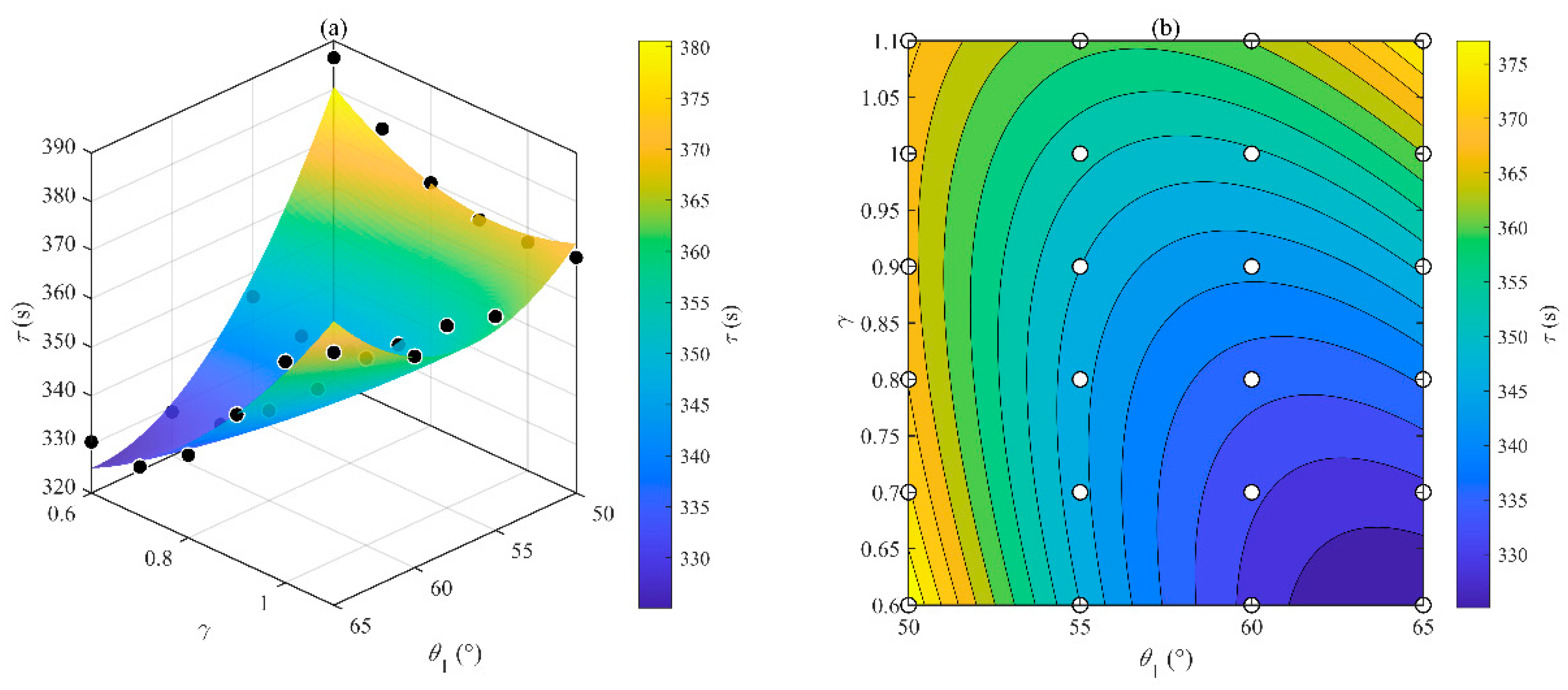
Figure 19: Response surface and contour plot of the hydrogen absorption time τ as a function of the secondary-fin included angle θ and the fin angle ratio γ: (a) fitted quadratic response surface with simulation data points (black markers); (b) corresponding contour plot.
As shown in Fig. 19a, the fitted quadratic surface descends monotonically from the upper-left corner (θ = 50°, γ = 1.1, τ = 368.5 s) toward the lower-right corner (θ = 65°, γ = 0.6, τ = 330.5 s), exhibiting distinct curvature along both axes rather than a planar tilt. In the contour projection, the iso-τ lines form a family of curved, obliquely-oriented arcs whose principal axis is misaligned with both coordinate directions, in which the minimum-τ region forms a curved trough in the (θ, γ) plane rather than a band aligned with either coordinate axis, indicating genuine parameter coupling that cannot be detected through a one-factor-at-a-time scan.
Taken together, these results confirm that the secondary-fin included angle and the fin angle ratio interact significantly in governing the hydrogen absorption time. For the remaining geometric parameters, either the volume-fraction constraint (in the case of β and r0) or the one-factor-at-a-time sampling strategy (in the case of α) precludes a statistically meaningful interaction analysis with the present dataset. A fully crossed design of experiments incorporating all six geometric variables is identified here as a direction for future investigation.
This study conducted a comparative CFD-based analysis of several tree-shaped finned-tube bundle geometries for a porous LaNi5 metal-hydride reactor. Using LaNi5 as the storage medium, a 2D numerical model was established to analyze the effects of geometric parameters—such as tube spacing, tube radius, and fin angles—and to mitigate reaction dead zone via extended fins. The primary conclusions are as follows:
- (1)Increasing the tube spacing ratio, α, monotonically shortens the absorption time over the tested range (0.8–1.2). α = 1.1 was adopted for subsequent optimization as it captures 92.7% of the achievable reduction (22.33% relative to α = 0.8) at a modest 1.59% increase in volume fraction, beyond which further increasing α to 1.2 yields only a marginal additional benefit (2.31%).
- (2)Increasing the tube radius ratio, β, generally enhances the reaction rate. Under optimal β conditions, a smaller primary tube radius, r0, improves temperature uniformity and constricts reaction dead zone. Among the investigated combinations, r0 = 1.5 mm and β = 1.2, provide the shortest absorption time of 341.5 s.
- (3)The secondary and tertiary fin angles dictate the spatial uniformity of the heat exchangers within the bed. Among the investigated angle combinations, θ = 60° and γ = 0.6 yields the shortest absorption time of 329 s, representing a 29.4% reduction from the pre-optimized state, with a marginal volume fraction increase of 1.9%.
- (4)Extending fins directly into reaction dead zone effectively enhances storage performance. When the distance from the extended fin tip to the lowest reacted fraction point is δ = 1 mm, the absorption time is reduced by 12.77% compared to the unoptimized dead-zone state, with only a 2.36% increase in volume fraction.
- (5)A response-surface analysis based on the existing parametric dataset reveals a statistically significant interactive effect between the secondary-fin included angle, θ, and the fin angle ratio, γ, on the hydrogen absorption time (R2 = 0.954, p < 0.001), confirming that the two parameters exert a coupled, rather than additive, influence on reactor performance.
In summary, the comparative analysis demonstrates that the geometric arrangement of the tree-shaped finned-tube bundle strongly affects the radial distribution of heat-removal capacity, the development of local hot regions, and the evolution of reaction dead zone. From a mechanistic perspective, the enhancement achieved by the tree-shaped finned-tube bundle originates from the hierarchical redistribution of heat transfer paths and cooling capacity within the MH bed, which suppresses local heat accumulation, alleviates the development of reaction dead zone, and maintains favorable conditions for hydrogen absorption throughout the reactor. Beyond these individual parameter effects, the response-surface analysis further demonstrates that the secondary-fin included angle and the fin angle ratio interact significantly in governing reactor performance, indicating that the geometric design of tree-shaped finned-tube bundles should account for such parameter coupling rather than relying solely on single-factor optimization. The findings of this work furnish quantitative design guidelines and a scalable structural template for the fluid-dynamic and heat-transfer optimization of MH-based solid-state hydrogen storage reactors, and are of direct relevance to engineering scenarios including on-board hydrogen storage for fuel-cell vehicles, distributed hydrogen refueling stations, and renewable-energy-coupled hydrogen storage systems. It should be pointed out that the present study is restricted to the hydrogen absorption process of a LaNi5-based laboratory-scale reactor, whereas the desorption behavior, long-term absorption-desorption cycling, scale-up effects in multi-tube parallel configurations, and experimental verification of the proposed geometry fall beyond the current scope and will be systematically addressed in our subsequent research.
Acknowledgement:
Funding Statement: This work was supported by the Natural Science Foundation of Shandong Province of China (No. ZR2023ME025).
Author Contributions: Haozhe Zhang: conceptualization, methodology, software, investigation, formal analysis, data curation, visualization, writing—original draft; Shengjie Wang: investigation, validation, formal analysis; Jiajia Song: data curation, investigation, visualization; Zeqi Chen: software, validation, visualization; Suoying He: methodology, resources, writing—review & editing, supervision; Ming Gao: conceptualization, funding acquisition, project administration, writing—review & editing, supervision. All authors reviewed and approved the final version of the manuscript.
Availability of Data and Materials: The data supporting the findings of this study are available from the corresponding author upon reasonable request. No new materials were generated in this study.
Ethics Approval: Not applicable.
Conflicts of Interest: Given his role as an Editorial Board Member of this journal, Suoying He had no involvement in the peer review of this article and had no access to information regarding its peer review. Full responsibility for the editorial process for this article was delegated to another journal editor. The authors declare no conflicts of interest.
Nomenclature
| Abbreviations | va | Average hydrogen storage rate, g/min | |
| MH | Metal hydride | Vbe,s | Volume occupied by heat transfer structure, m3 |
| LTE | Local thermal equilibrium | V0,s | Total MH region volume without heat transfer structure, m3 |
| CFD | Computational fluid dynamics | X | Reacted fraction, — |
| RSM | Response surface methodology | Greek symbols | |
| Symbols | α | Common ratio of heat exchanger tube spacing, — | |
| A | Van’t Hoff constant for hydrogen absorption, — | β | Common ratio of heat exchanger tube radius, — |
| B | Van’t Hoff constant for hydrogen absorption, K | γ | Common ratio of fin included angle, — |
| Ca | Hydrogen absorption rate constant, 1/s | δ | Fin extension distance, mm |
| cp | Specific heat capacity, J/(kg·K) | ΔH | Heat of reaction for hydrogen absorption, J/mol |
| dp | MH particle size, μm | ε | Porosity, — |
| Ea | Activation energy for hydrogen absorption, J/mol | θ | Secondary-fin included angle, ° |
| H | Height of the upper hydrogen region, mm | λ | Thermal conductivity, W/(m·K) |
| K | Permeability of the porous MH bed, m2 | μg | Dynamic viscosity of hydrogen, kg/(m·s) |
| L0 | Spacing between the primary and secondary heat-exchanger tubes, mm | ρ | Density, kg/m3 |
| αL0 | Spacing between secondary and tertiary heat exchanger tubes, mm | τ | Hydrogen storage time, s |
| α2L0 | Distance from the tertiary tube axis to the tertiary fin outer edge, mm | φ | Heat transfer structure volume fraction, % |
| m | Total mass of absorbed hydrogen, g | Subscripts and Superscripts | |
| ṁ | Volumetric hydrogen mass source term, kg/(m3·s) | 0 | Initial |
| M | Relative molecular mass, kg/mol | a | Absorption |
| p | Pressure, Pa | Al | Aluminum |
| R | Gas constant, J/(mol·K) | be | Corrugation period |
| r’ | Radial distance from the reactor axis, mm | eff | Effective |
| r0 | Primary heat-exchanger tube radius, mm | eq | Equilibrium |
| βr0 | Secondary heat exchanger tube radius, mm | f | Fluid |
| β2r0 | Tertiary heat exchanger tube radius, mm | g | Gas |
| t | Time, s | ref | Reference |
| T | Temperature, K | s | Solid |
| u | Hydrogen superficial velocity in the MH bed, m/s | sat | Saturation |
References
1. Li JL , Shao CX , Zhang ZD , Liang ZH , Zeng F . Analysis of hydrogen industry policy and commercialization model. Power Gener Technol. 2023; 44( 3): 287– 95. (In Chinese). doi:10.12096/j.2096-4528.pgt.22185. [Google Scholar] [CrossRef]
2. Lahmer K , Bessaih R , Scipioni A , El Ganaoui M . Simulation of hydrogen absorption in a magnesium hydride tank. Fluid Dyn Mater Process. 2014; 10( 1): 149– 62. doi:10.3970/fdmp.2014.010.149. [Google Scholar] [CrossRef]
3. Bai C , Zhao H , Tian M . Numerical simulation for hydrogenation process inside metal hydride canister and optimized fin structure for minimized hydrogenation time. Int Commun Heat Mass Transf. 2025; 164: 108863. doi:10.1016/j.icheatmasstransfer.2025.108863. [Google Scholar] [CrossRef]
4. Zheng J , Liu X , Xu P , Liu P , Zhao Y , Yang J . Development of high pressure gaseous hydrogen storage technologies. Int J Hydrogen Energy. 2012; 37( 1): 1048– 57. doi:10.1016/J.IJHYDENE.2011.02.125. [Google Scholar] [CrossRef]
5. Wang X , Zhao H , Zhao H , Yu H , Dong X , Zheng Q , et al. Hydrogen storage performance of a novel metal hydride reactor coupled with spider web fins and phase change materials. J Energy Storage. 2025; 125: 116993. doi:10.1016/j.est.2025.116993. [Google Scholar] [CrossRef]
6. Jiang L . Expediting the innovation and application of solid hydrogen storage technology. Engineering. 2021; 7( 6): 731– 3. doi:10.1016/j.eng.2021.04.008. [Google Scholar] [CrossRef]
7. Chen J , Chai H , Yu Y , Li W , Ao Y , Wu X . Numerical investigation on the hydrogen storage performance improvement of metal hydride reactor induced by expanded surfaces. Appl Therm Eng. 2025; 266: 125688. doi:10.1016/j.applthermaleng.2025.125688. [Google Scholar] [CrossRef]
8. Nguyen HQ , Shabani B . Review of metal hydride hydrogen storage thermal management for use in the fuel cell systems. Int J Hydrogen Energy. 2021; 46( 62): 31699– 726. doi:10.1016/j.ijhydene.2021.07.057. [Google Scholar] [CrossRef]
9. Krishna KV , Pandey V , Maiya MP . Bio-inspired leaf-vein type fins for performance enhancement of metal hydride reactors. Int J Hydrogen Energy. 2022; 47( 56): 23694– 709. doi:10.1016/j.ijhydene.2022.05.163. [Google Scholar] [CrossRef]
10. Miao G , Li P , Liu C , Liu Y , Zhang H , Lin F , et al. Review of thermal management technology for metal hydride reaction beds. Sustain Energy Fuels. 2023; 7( 9): 2025– 41. doi:10.1039/d2se01690g. [Google Scholar] [CrossRef]
11. Larpruenrudee P , Bennett NS , Gu Y , Fitch R , Islam MS . Design optimization of a magnesium-based metal hydride hydrogen energy storage system. Sci Rep. 2022; 12( 1): 13436. doi:10.1038/s41598-022-17120-3. [Google Scholar] [CrossRef]
12. Bao Z , Wu Z , Nyamsi SN , Yang F , Zhang Z . Three-dimensional modeling and sensitivity analysis of multi-tubular metal hydride reactors. Appl Therm Eng. 2013; 52( 1): 97– 108. doi:10.1016/j.applthermaleng.2012.11.023. [Google Scholar] [CrossRef]
13. Meng X , Wu Z , Bao Z , Yang F , Zhang Z . Performance simulation and experimental confirmation of a mini-channel metal hydrides reactor. Int J Hydrogen Energy. 2013; 38( 35): 15242– 53. doi:10.1016/j.ijhydene.2013.09.056. [Google Scholar] [CrossRef]
14. Kudiiarov V , Elman R , Pushilina N , Kurdyumov N . State of the art in development of heat exchanger geometry optimization and different storage bed designs of a metal hydride reactor. Materials. 2023; 16( 13): 4891. doi:10.3390/ma16134891. [Google Scholar] [CrossRef]
15. Raju NN , Muthukumar P , Selvan PV , Malleswararao K . Design methodology and thermal modelling of industrial scale reactor for solid state hydrogen storage. Int J Hydrogen Energy. 2019; 44( 36): 20278– 92. doi:10.1016/j.ijhydene.2019.05.193. [Google Scholar] [CrossRef]
16. Mohan G , Prakash Maiya M , Srinivasa Murthy S . Performance simulation of metal hydride hydrogen storage device with embedded filters and heat exchanger tubes. Int J Hydrogen Energy. 2007; 32( 18): 4978– 87. doi:10.1016/j.ijhydene.2007.08.007. [Google Scholar] [CrossRef]
17. Nyamsi SN , Tolj I , Pasupathi S . Multi-objective optimization of a metal hydride reactor coupled with phase change materials for fast hydrogen sorption time. J Energy Storage. 2023; 71: 108089. doi:10.1016/j.est.2023.108089. [Google Scholar] [CrossRef]
18. Bai XS , Yang WW , Tang XY , Yang FS , Jiao YH , Yang Y . Optimization of tree-shaped fin structures towards enhanced absorption performance of metal hydride hydrogen storage device: A numerical study. Energy. 2021; 220: 119738. doi:10.1016/j.energy.2020.119738. [Google Scholar] [CrossRef]
19. Chang H , Tao YB , Wang WY . Numerical study on storage performance of metal hydride reactors with multiple spiral fins. Int J Hydrogen Energy. 2023; 48( 90): 35170– 84. doi:10.1016/j.ijhydene.2023.05.248. [Google Scholar] [CrossRef]
20. Gkanas EI , Grant DM , Khzouz M , Stuart AD , Manickam K , Walker GS . Efficient hydrogen storage in up-scale metal hydride tanks as possible metal hydride compression agents equipped with aluminium extended surfaces. Int J Hydrogen Energy. 2016; 41( 25): 10795– 810. doi:10.1016/j.ijhydene.2016.04.035. [Google Scholar] [CrossRef]
21. Parida A , Sunku Prasad J , Muthukumar P , Dalal A . A dynamic model for predicting the absorption and desorption behaviors of metal hydride systems and its implementation for screening of alloys for metal hydride hydrogen compressor. Int J Hydrogen Energy. 2024; 51: 454– 72. doi:10.1016/j.ijhydene.2023.06.275. [Google Scholar] [CrossRef]
22. Chandra S , Sharma P , Muthukumar P , Tatiparti SSV . Modeling and numerical simulation of a 5 kg LaNi5-based hydrogen storage reactor with internal conical fins. Int J Hydrogen Energy. 2020; 45( 15): 8794– 809. doi:10.1016/j.ijhydene.2020.01.115. [Google Scholar] [CrossRef]
23. Mou X , Bao Z , Huang W . Performance investigation of metal hydride reactor equipped with helically coiled heat exchanger during hydrogen absorption and desorption. Therm Sci Eng Prog. 2023; 38: 101656. doi:10.1016/j.tsep.2023.101656. [Google Scholar] [CrossRef]
24. Jemni A , Ben Nasrallah S , Lamloumi J . Experimental and theoretical study of ametal–hydrogen reactor. Int J Hydrogen Energy. 1999; 24( 7): 631– 44. doi:10.1016/S0360-3199(98)00117-7. [Google Scholar] [CrossRef]
25. Bai XS , Yang WW , Yang YJ , Zhang KR , Yang FS . Multi-variable optimization of metal hydride hydrogen storage reactor with gradient porosity metal foam and evaluation of comprehensive performance. Int J Hydrogen Energy. 2022; 47( 83): 35340– 51. doi:10.1016/j.ijhydene.2022.08.123. [Google Scholar] [CrossRef]
26. Wang Y , Zhang H , Qi J , Han K , He S , Guo C , et al. Thermodynamic and exergy analysis of a novel PEMFC-ORC-MH combined integrated energy system. Energy Convers Manag. 2022; 264: 115709. doi:10.1016/j.enconman.2022.115709. [Google Scholar] [CrossRef]
27. Jemni A , Ben Nasrallah S . Study of two-dimensional heat and mass transfer during absorption in a metal-hydrogen reactor. Int J Hydrogen Energy. 1995; 20( 1): 43– 52. doi:10.1016/0360-3199(93)E0007-8. [Google Scholar] [CrossRef]
28. Tong L , Xiao J , Yang T , Bénard P , Chahine R . Complete and reduced models for metal hydride reactor with coiled-tube heat exchanger. Int J Hydrogen Energy. 2019; 44( 30): 15907– 16. doi:10.1016/j.ijhydene.2018.07.102. [Google Scholar] [CrossRef]
29. Bai XS , Yang WW , Tang XY , Dai ZQ , Yang FS . Parametric optimization of coupled fin-metal foam metal hydride bed towards enhanced hydrogen absorption performance of metal hydride hydrogen storage device. Energy. 2022; 243: 123044. doi:10.1016/j.energy.2021.123044. [Google Scholar] [CrossRef]
30. Wang W , Wang M , Wang J , Chen X , Xu W , Wang W . Numerical study on hydrogen desorption performance of a new MgH2 solid-state hydrogen storage device. Int J Hydrogen Energy. 2024; 86: 530– 41. doi:10.1016/j.ijhydene.2024.08.462. [Google Scholar] [CrossRef]
31. Li H , Wang Y , He C , Chen X , Zhang Q , Zheng L , et al. Design and performance simulation of the spiral mini-channel reactor during H2 absorption. Int J Hydrogen Energy. 2015; 40( 39): 13490– 505. doi:10.1016/j.ijhydene.2015.08.066. [Google Scholar] [CrossRef]
32. Chabane D , Harel F , Djerdir A , Ibrahim M , Candusso D , Elkedim O , et al. Influence of the key parameters on the dynamic behavior of the hydrogen absorption by LaNi5. Int J Hydrogen Energy. 2017; 42( 2): 1412– 9. doi:10.1016/j.ijhydene.2016.06.110. [Google Scholar] [CrossRef]
33. Bi W , Hou Y , Wan J , Hu J , Yu M , Xu X , et al. Influence of corrugated tube structure and flow rate on the hydrogen absorption performance of metal hydride reactor and structural optimization. Process Saf Environ Prot. 2024; 190: 97– 109. doi:10.1016/j.psep.2024.07.028. [Google Scholar] [CrossRef]
34. Ben Nasrallah S , Jemni A . Heat and mass transfer models in metal-hydrogen reactor. Int J Hydrogen Energy. 1997; 22( 1): 67– 76. doi:10.1016/S0360-3199(96)00039-0. [Google Scholar] [CrossRef]
35. Chung CA , Ho CJ . Thermal–fluid behavior of the hydriding and dehydriding processes in a metal hydride hydrogen storage canister. Int J Hydrogen Energy. 2009; 34( 10): 4351– 64. doi:10.1016/j.ijhydene.2009.03.028. [Google Scholar] [CrossRef]
36. Bejan A . Constructal-theory network of conducting paths for cooling a heat generating volume. Int J Heat Mass Transf. 1997; 40( 4): 799– 816. doi:10.1016/0017-9310(96)00175-5. [Google Scholar] [CrossRef]
37. Alebrahim A , Bejan A . Constructal trees of circular fins for conductive and convective heat transfer. Int J Heat Mass Transf. 1999; 42( 19): 3585– 97. doi:10.1016/S0017-9310(99)00021-6. [Google Scholar] [CrossRef]
Cite This Article
 Copyright © 2026 The Author(s). Published by Tech Science Press.
This work is licensed under a Creative Commons Attribution 4.0 International License , which permits unrestricted use, distribution, and reproduction in any medium, provided the original work is properly cited.
 Downloads
 Citation Tools
