
 Login
Login Register
 Submit a Paper
 Propose a Special lssue
 Open Access
ARTICLE
Effect of Nozzle Orifice Number on Jet Dynamics and Rock-Breaking Performance of Multi-Orifice Abrasive Water Jets
1 Power China Zhongnan Engineering Corporation Limited, Changsha, China
2 School of Energy and Power Engineering, Changsha University of Science and Technology, Changsha, China
3 School of Hydraulic and Ocean Engineering, Changsha University of Science and Technology, Changsha, China
* Corresponding Author: Dongping Zeng. Email:
Fluid Dynamics & Materials Processing 2026, 22(9), 5 https://doi.org/10.32604/fdmp.2026.088471
Received 04 July 2026; Accepted 21 September 2026; Issue published 28 September 2026
 View Full Text
 Download PDF
Abstract
The influence of nozzle orifice number on the jet dynamics and rock-breaking performance of multi-orifice abrasive water jets (MOAWJ) is systematically examined for precision drilling in pumped storage power station construction. A VOF-DPM (Volume of Fluid–Discrete Phase Model) two-way coupling framework is first employed to characterize the flow-field structure, velocity distribution, and spatial evolution of abrasive particles for different orifice configurations. The resulting jet characteristics are then used as initial conditions in an SPH-FEM (Smoothed Particle Hydrodynamics-Finite Element Method) coupling model to simulate the transient rock-breaking process and elucidate the underlying micromechanical mechanisms. The results show that increasing the number of orifices reduces inlet throttling and abrasive-particle agglomeration, while improving flow uniformity among the individual orifices and maintaining better jet collimation. The mean water-phase velocity at the outlet is only weakly dependent on the orifice count and remains approximately 231 m/s. In contrast, the mean abrasive-phase velocity initially decreases and then increases with increasing orifice number, reaching a maximum of 205.80 m/s for the seven-orifice configuration. Increasing the orifice count also broadens the spatial distribution of abrasive particles, reduces the pronounced asymmetry observed near the side orifices, and promotes a more uniform distribution of erosive action. The rock-breaking process exhibits four distinct stages, while increasing the number of orifices enhances inter-orifice stress superposition and water-wedge effects, driving a transition in the dominant failure mechanism from depth-controlled to area-controlled rock removal. At 300 μs, the seven-orifice configuration produces a total rock-breaking volume 85.3% greater than that obtained with four orifices.Keywords
To achieve the global strategic goals of carbon peaking and carbon neutrality, countries worldwide are accelerating the large-scale integration of new energy sources represented by wind and photovoltaic power into power grids, which has led to a sharp increase in volatility and uncertainty on both the supply and demand sides of the power system. PSH (pumped storage hydropower) has become an indispensable pillar of flexible regulation resources for building a new power system, owing to its comprehensive advantages of technological maturity, large scale, long lifespan, and low levelized cost of storage [1,2,3]. The core of PSH plant construction lies in the excavation and support of large-scale underground cavern complexes, the safety and efficiency of which are highly dependent on precision drilling technology throughout the entire project lifecycle [4,5]. However, plant sites often face challenges posed by hard and highly abrasive rock formations, such as granite [6]. Traditional mechanical drilling methods suffer from significant drawbacks, including severe tool wear, low drilling efficiency, and high construction costs [7]. Therefore, there is an urgent need to develop new, efficient rock-breaking drilling technologies capable of adapting to complex geological conditions.
AWJ (abrasive water jet) technology, as a non-contact cold processing method, utilizes high-pressure water to accelerate abrasive particles, forming a high-speed jet that achieves rock breakage through erosion and crack propagation. It demonstrates unique potential for tackling hard rock and reducing tool wear [8,9,10]. Employing it as a pre-breaking or auxiliary rock-breaking process offers a promising innovative solution for the safe and efficient construction of PSH plants [11]. Various optimized variants have been developed based on conventional abrasive water jet technology, such as improving jet machining performance by adding polymer additives [12] and enhancing jet impact efficiency through nozzle structure optimization [13] and multi-orifice design [14]. Among these variants, MOAWJ, as a significantly improved configuration of traditional AWJ technology, has emerged as a prominent research focus in this field. For the multi-orifice jet technology, scholars at home and abroad have carried out a series of research on the nozzle structure design, rock-breaking performance verification and other aspects. At the nozzle structure design level, Chi et al. [15] built a systematic design framework of multi-orifice nozzle with double evaluation indexes of flow coefficient and self-advancing thrust, and proposed that the optimal number of front nozzle orifices was 6 to 7 and the appropriate inclination range was 12.5° to 22.5°; Bi et al. [16] developed a new rotary-jet multi-orifice bit suitable for radial horizontal wells, and determined the optimal structural parameters: the central nozzle is collinear with the tool axis, the deflection angle of the central forward nozzle is 20°, and the deflection angle and divergence angle of the outer nozzles are 20° and 15°, respectively; Ba et al. [17] used RNG k-ε (Renormalization Group k-epsilon turbulence model) to carry out numerical analysis of the flow field of the gradient jet orifice scheme, and clarified that the 20° and 30° low angle jet orifice realized deep hole drilling with high axial flow rate, and the 60° high angle jet orifice completed reaming operation with radial flow rate, completely revealing the mechanism of progressive superposition borehole formation under the coupling effect of multiple jets; Lu et al. [18] designed a self-propelled multi-orifice nozzle, taking rock-breaking performance and self-advancing capacity as evaluation indicators, they optimized the nozzle structure and obtained the optimal parameter combination with an axial angle of 25° and a radial angle of 90° for the forward jet orifices; Song et al. [19,20] carried out comparative simulation of four-orifice and five-orifice configurations for geothermal high-temperature multi-orifice hot jet nozzle, and proved that the comprehensive performance of five-orifice nozzle was better than four-orifice from three dimensions of high-temperature fluid heat transfer, bottom hole pressure and cuttings transportation, providing reference for the design of multi-orifice aperture and circumferential arrangement under high temperature conditions; In terms of rock breaking mechanism and performance research, Zhu et al. [21] used ALE (Arbitrary Lagrangian–Eulerian) algorithm to reveal the damage evolution law of multi-orifice water jet under high confining pressure, and verified its advantages of reaming and drilling stability; Lu et al. [22] revealed the rock-breaking mechanism of self-rotating orifice water jets through CT scanning and scanning electron microscope observations: the cyclic impact can effectively weaken the water cushion effect; rock failure is dominated by brittle tensile fracture, generating transgranular and intergranular cracks, and presenting a multi-mechanism coupling mode of impact damage, crack propagation and rock chip spalling; Liu et al. [23] optimized the spray orifice arrangement of self rotating bit, and the performance of three front sprays outperforms double front sprays: although the two-orifice configuration boasts the maximum flow coefficient, the three-orifice layout eliminates rock-breaking blind zones and delivers superior comprehensive performance; Ge et al. [24] studied and compared two kinds of multi-orifice configurations without central orifice and with central orifice, the rock breaking efficiency of the scheme with central jet can be improved by 47.3%, and the boss at the bottom of the hole can be completely eliminated when the orifice spacing is less than 2.8 mm; Lu et al. [25] analyzed the regulation laws of nozzle arrangement distance, diameter and axial angle of orifice nozzles on rock-breaking depth and rock-breaking volume, and pointed out that for a drill bit with a diameter of 12 mm, the optimal nozzle arrangement distance is 2.1 mm; Chi et al. [26] investigated and verified the borehole-extending capability of the orifice radial jet technology, and concluded that increasing the pump flow rate can effectively extend borehole length, while optimizing the nozzle flow distribution can significantly improve drilling operation performance and borehole quality.
Existing studies have confirmed the technical advantages of MOAWJ in terms of hole-forming efficiency and contour control, but most of them focus on pure water jet or low-pressure coal and rock conditions. Under the condition of high-pressure AWJ, the influence of nozzle orifice count on the gas-liquid-solid three-phase flow field structure, velocity distribution, and dynamic characteristics of abrasive particle space evolution in the jet has not been systematically elucidated. In addition, there is insufficient research on the microscopic mechanism of inter-orifice synergistic rock-breaking of MOAWJ and the quantitative transformation law of rock-breaking mode with the orifice count, which is difficult to directly support the fine-grained design of the nozzle for precision drilling in hard rock formation of pumped storage.
Therefore, based on the engineering requirements of precision drilling in pumped storage power station, this study takes four-orifice to seven-orifice MOAWJ as the research object. The VOF-DPM bidirectional coupling model is used to systematically analyze jet flow field structures and velocity distributions under different orifice counts, and clarify the spatial distribution characteristics of abrasive particles. We further couple the SPH-FEM algorithm to conduct granite rock-breaking simulations with jet dynamic characteristics as initial boundary conditions, and reveal the micromechanism of orifice count regulating rock-breaking efficiency and failure modes. The research results can provide theoretical support and design basis for the application of MOAWJ rock-breaking technology in the precision drilling of pumped storage hard rock formation.
2 Mathematical Model and Geometric Model
The VOF (Volume of Fluid) method is only used to solve the macroscopic free-surface between water and ambient air, and is not used to characterize the phase interfaces of discrete abrasive particles. The abrasive volume fraction of the AWJ in this study is merely about 1%, which falls into the dilute-phase dispersed system. The multi-fluid method based on the Euler-Euler framework is more applicable to dense-phase particle flow systems. In contrast, the VOF-DPM method adopted in this paper, which is built on the Euler-Lagrange framework, can accurately track the motion trajectories and momentum transfer processes of individual particles, and better capture the discrete spatial distribution and anisotropic characteristics of abrasive particles. This coupling scheme avoids the interface resolution defects that occur when the VOF method is directly applied to particle-bubble flows. It has been extensively validated and applied in the numerical simulation of gas-liquid-solid three-phase flow inside abrasive water jet nozzles [27], which demonstrates the rationality and accuracy of the method selected in this paper.
In this study, the VOF-DPM model is used to describe the gas-liquid-solid three-phase coupling process in MOAWJ. The VOF is used to capture the free interface of the gas-liquid two-phase, and the DPM (Discrete Phase Model) is used to track the trajectory of abrasive particles, and the bidirectional coupling between the two-phase flow and particles is considered. The RNG k-ε model is selected as the turbulence model. The PISO algorithm is adopted for pressure-velocity coupling. In terms of spatial discretization, the PRESTO! scheme is used for pressure solution, and the second-order upwind scheme is employed to solve the momentum and turbulent terms. The discrete random walk model is activated for DPM. Before injecting particles in the transient DPM calculation, the flow field reaches convergence via steady-state computation. Since an excessively small-time step consumes massive computational resources while an overlarge time step tends to cause numerical divergence, an appropriate time step of 1 × 10⁻⁶ s was chosen [27,28,29].
The VOF-DPM model adopts differential-form governing equations for continuous-phase flow. The mass conservation, momentum conservation, mixture property relations and volume-fraction transport equation are given in Eqs. (1)–(8) [30]:
Fp,i is the reaction force from abrasive particles on the fluid (two-way coupling source term), computed from the discrete phase model (DPM):
RNG k-ε is used for the continuous phase. This model can improve the prediction accuracy of vortex structure and recirculation zone, and its governing equation is shown in Eqs. (9) and (10) [31]:
The motion equation of abrasive particles is [32]:
In the two-way coupling calculation, the flow field and particle information are exchanged iteratively in each time step: first, the VOF flow field is solved, then the particle position and force are updated, and the reaction force of particles on the fluid is fed back to the flow field equation in the form of source term. This two-way coupling mechanism fully considers the local momentum transfer between the continuous water phase and discrete abrasive particles: the velocity change of the water phase directly drives the acceleration and deceleration of particles, while the velocity fluctuation and disturbance of the particle phase will in turn modify the local velocity profile of the liquid phase, so as to realize the interaction between abrasive particles and jet flow field [33].
2.2 Geometric Model and Boundary Conditions
The multi-orifice nozzle consists of multiple single-orifice nozzles, each with a straight inlet section, a conical contraction section, and a straight outlet section. Refer to Table 1 for the geometric structure and outlet flow domain dimensions. The real object and model of the multi-orifice nozzle are shown in Fig. 1. The computational domain is discretized with structured grids, and the central region with dramatic changes in jet velocity is meshed.
The jet pressure is set at 30 MPa, the wall is no-slip wall, and the abrasive is 80-mesh garnet. The abrasive mass flow is fine-tuned according to the flow of the MOAWJ with different orifice counts, so that the corresponding abrasive volume fraction is about 1%. The abrasive mass flow of the MOAWJ with four-orifice to seven-orifice is 0.227 kg/s, 0.285 kg/s, 0.340 kg/s, 0.396 kg/s, respectively. The abrasive inlet surface is set as the random starting point. The specific boundary conditions and initial condition parameter settings are shown in Table 2.
Table 1: Parameters of multi-orifice nozzle.
| Parameters of Multi-Orifice Nozzle | Value | Parameters of Multi-Orifice Nozzle | Value |
|---|---|---|---|
| Orifice count | 4; 5; 6; 7 | The free jet area outside the nozzle length/(mm) | 150 |
| The pipe at the front end of the nozzle length/(mm) | 25 | Center distance between central nozzles and side nozzles/(mm) | 15 |
| Straight pipe section length at nozzle inlet end/(mm) | 10 | The nozzle inlet diameter/(mm) | 9 |
| Nozzle contraction section length/(mm) | 23 | The nozzle outlet diameter/(mm) | 3 |
| Straight pipe length at nozzle outlet end/(mm) | 11 | The free jet area outside the nozzle diameter/(mm) | 60 |
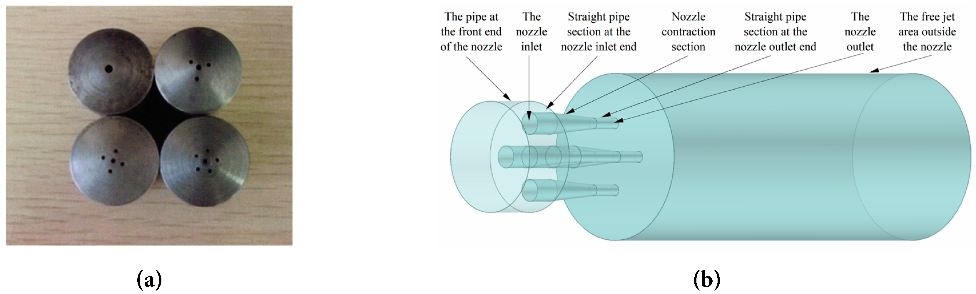
Figure 1: Geometric models of multi-orifice nozzles and multi-orifice jets (a) physical object of multi-orifice nozzle; (b) multi-orifice jet model.
Table 2: Parameters of boundary conditions and initial conditions.
| MOAWJ Parameters | Value | MOAWJ Parameters | Value |
|---|---|---|---|
| Nozzle Inlet Pressure/(MPa) | 30 | Density of water/(kg·m−3) | 998 |
| Nozzle outlet pressure/(MPa) | 0.1 | Viscosity of water/(mPa·s) | 1 |
| Abrasive particle size/(mm) | 0.18 | Abrasive volume fraction | 1% |
| Abrasive density/(kg·m−3) | 3500 |
2.3 Numerical Model Verification
Fig. 2 shows the results of grid independence verification and method reliability verification. As shown in Fig. 2a, the five-orifice AWJ simulation with an inlet pressure of 30 MPa was carried out with different grid numbers. When the grid number reached 6.31 million, the minimum orthogonal quality of the grid was 0.601, the minimum volume was 8.2e−3 mm3, and the nozzle outlet velocity tended to be stable. The grid number was determined to be the minimum number of computational grids. In addition, Fig. 2b compares the 5 MPa single orifice AWJ velocity reproduced by the VOF-DPM model with the AWJ velocity under the same parameters and working conditions in the literature [34], showing good consistency, which proves that the model parameter setting is reasonable and the simulation accuracy is reliable.
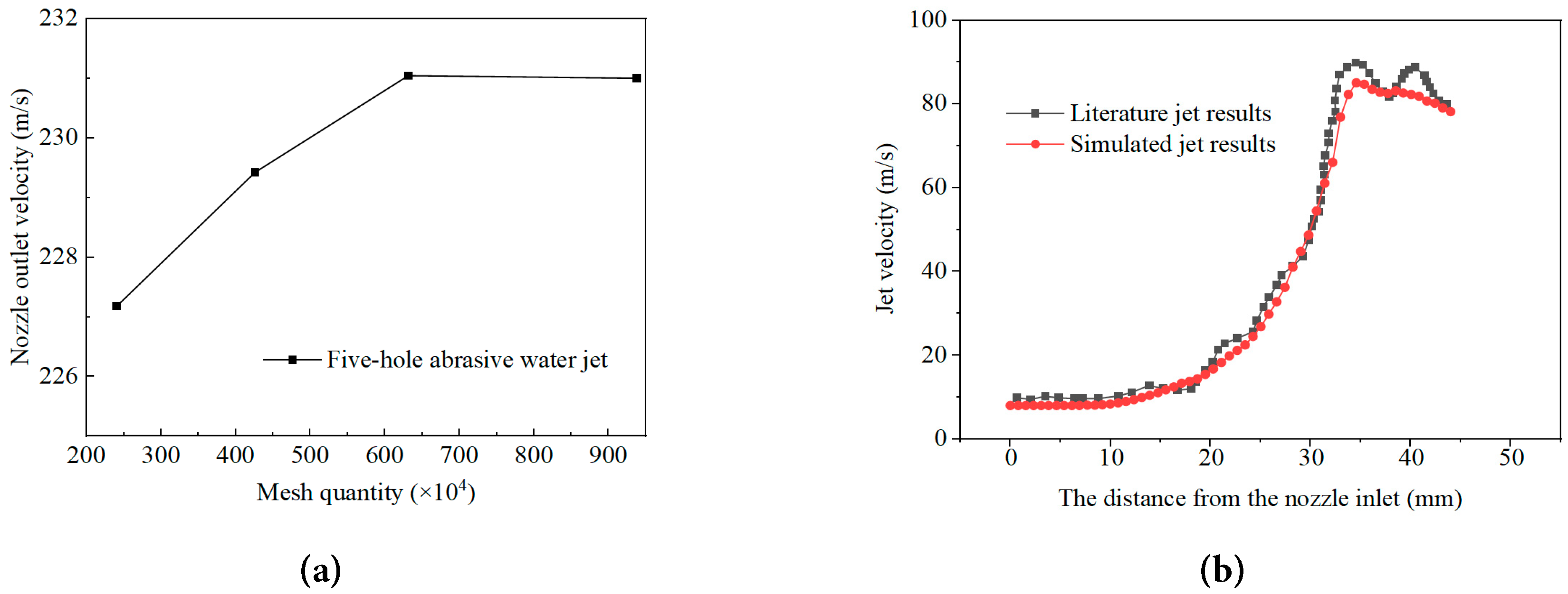
Figure 2: Grid independence verification and method reliability verification (a) grid independence verification; (b) comparison of simulated jet velocity with literature results [34].
2.4 Rock Breaking Model and Material Parameters
The crushing process of rock under the action of AWJ is accompanied by complex phenomena such as hypervelocity collision, large deformation and fracture failure. The traditional FEM method has the inherent defect of mesh distortion when simulating such large deformation problems [35]. In this study, the SPH-FEM coupling algorithm is introduced for numerical simulation, in which the water and abrasive are modeled by SPH particles, and the rock target is discretized by FEM elements. The interface coupling between the two is realized by penalty function. The algorithm has both good calculation accuracy and solution efficiency and can completely reproduce the whole process of jet impact, rock damage development and fragmentation expansion [36,37]. The jet phase is described by the NULL material model and Mie-Grüneisen equation of state, and the parameters of the water and abrasive model are shown in Table 3. The rock model adopts the granite RHT (Riedel–Hiermaier–Thoma) constitutive model with uniaxial compressive strength of 119 MPa, which can adapt to the dynamic failure process of granite under high strain rate and large deformation. Its core parameters are shown in Table 4, and other constitutive parameters are shown in reference [38].
Table 3: Model parameters of water and abrasives.
| Materials | ρ0/(kg·m−3) | C/(m·s−1) | S1 | S2 | S3 | a | γ0 |
|---|---|---|---|---|---|---|---|
| Water | 1000 | 1480 | 2.56 | −1.99 | 1.2268 | 0 | 0.35 |
| Abrasive | 3500 | 4569 | 1.49 | 0 | 0 | 0 | 2.17 |
Table 4: Constitutive parameters of granite.
| Parameters | Value | Parameters | Value | Parameters | Value |
|---|---|---|---|---|---|
| mass density ρ0/(kg·m−3) | 2700 | Failure plane parameter N | 0.56 | Fracture surface parameter A | 1.6 |
| shear modulus of elasticity G/(MPa) | 24,170 | Relative tensile strength ft | 0.1 | Porosity Index Np | 4 |
| Uniaxial Compressive Strength fc/(MPa) | 119 | relative shear strength fs | 0.38 | Initial porosity α | 1.1 |
The rock-breaking model of the jet is shown in Fig. 3. The size of the rock model is 80 mm × 80 mm × 50 mm. The non-reflective boundary, defined using the keyword BOUNDARY_NON_REFLECTING, is applied on the bottom and four sides to simulate the semi-infinite rock mass, with a target distance of 10 mm. The coupling contact between SPH particles and FEM rock elements is realized via the keyword CONTACT_ERODING_NODES_TO_SURFACE. The soft contact option (SOFT = 1) is enabled to mitigate the penetration of SPH particles into the solid elements. The time step scale factor (TSSFAC) is set to 0.67, and the hourglass coefficient is defined as 0.1. A fixed rigid shell is set outside the jet beam to eliminate the interference of the reflected jet on the incoming jet and the subsequent jet. The velocity of the MOAWJ and the abrasive distribution area obtained from the jet simulation are derived, and the simplified assumptions that the abrasive and water are given initial values at their respective average velocities and the abrasive is uniformly and randomly distributed in the abrasive distribution area are made as the initial and boundary conditions of the jet in the subsequent simulation of MOAWJ rock breaking. SPH particles were generated by filling the jet domain with an initial spacing of 0.2 mm in the x, y and z directions, yielding a total of 74,220 particles. The FEM rock mesh had a size of 0.4 mm. The total number of FEM elements was 5 × 10⁷. When the particle spacing was reduced to 0.1 mm and the FEM mesh size was refined to 0.2 mm, the rock erosion volume at 300 μs, which only had a relative difference of approximately 2% compared with the result of the original model 4.385 mm3. However, the refined model exhibited a dramatic increase in file size and computational cost. Therefore, the model with an FEM mesh size of 0.4 mm and SPH particle spacing of 0.2 mm was selected for subsequent simulations.
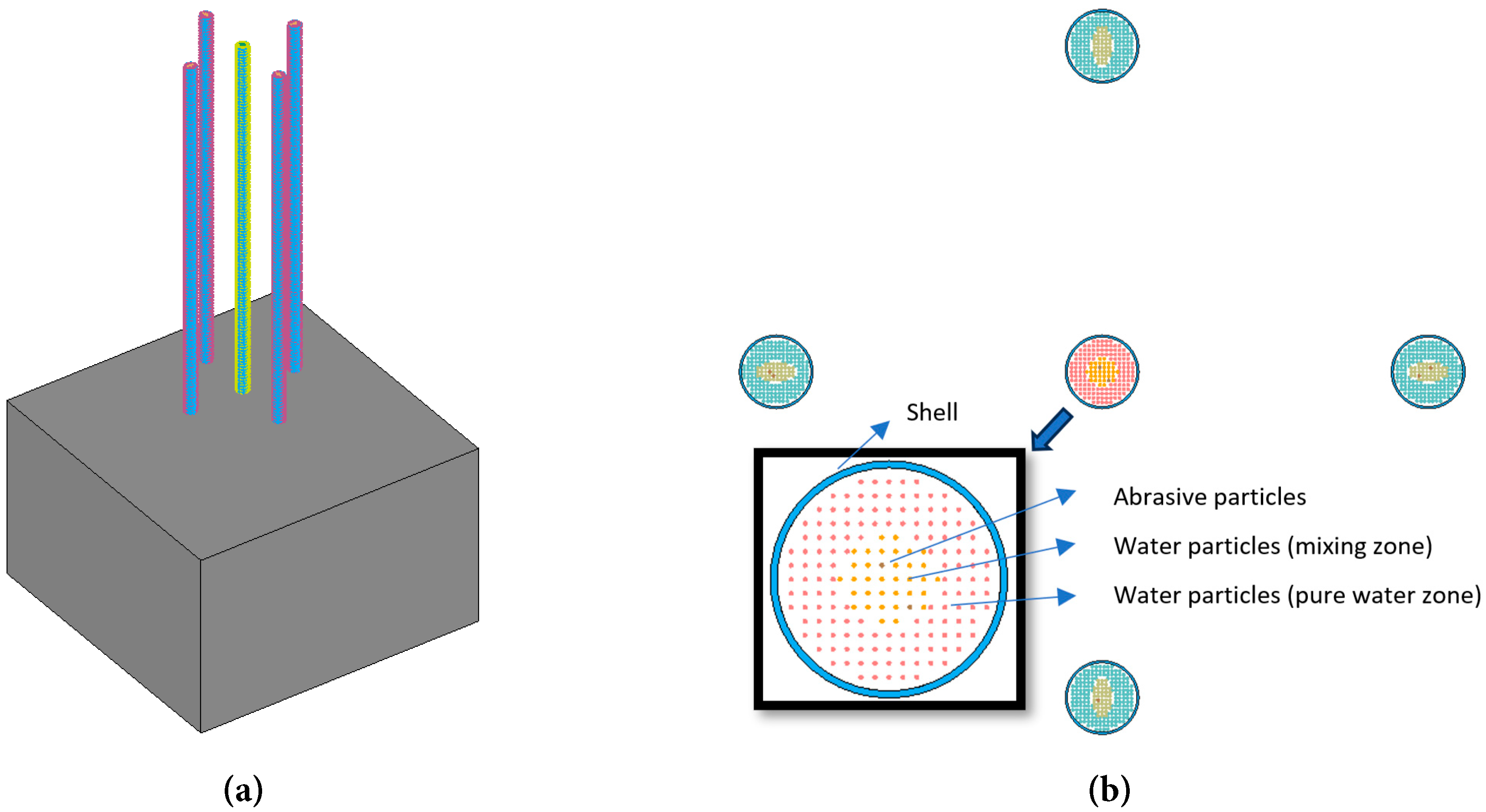
Figure 3: Five-orifice AWJ rock breaking model (a) overall model diagram; (b) top view of five-orifice AWJ.
3.1 Flow Field Structure and Velocity Distribution Characteristics of MOAWJ
Regarding the gas phase in the established gas-liquid-solid three-phase VOF-DPM model, it is mainly confined to the free interface region at the jet periphery and the interaction zone between the jet and ambient air. The core region of the jet that dominates rock-breaking behavior is dominated by high-velocity water-abrasive two-phase flow, while the gas phase only participates in the entrainment and diffusion process of the jet boundary layer, and the evolution of the gas-liquid interface has been fully captured by the VOF method. Since the rock-breaking effect of the abrasive water jet is mainly driven by the high-speed impact of the water-abrasive two-phase core jet, the direct contribution of the gas phase to rock-breaking performance is negligible. For this reason, the subsequent rock-breaking analysis focuses on the dynamic characteristics of the water-abrasive two-phase jet.
Fig. 4 shows the particle trajectory and water velocity contour of MOAWJ under different nozzle orifice counts. The maximum velocity of the jet is 244 m/s, showing the macro flow mechanical characteristics of the whole process of the jet from inlet throttling, contraction section acceleration, outlet velocity peak to downstream diffusion attenuation. When the orifice count is small, the total flow area of the nozzle is small, the inlet throttling effect is significant, the turbulent fluctuation is strong, and the abrasive particles are easy to stay and agglomerate in the inlet area, resulting in high local particle concentration in the nozzle. With the increase of the orifice count, the uniformity of the inlet flow field is improved, the particle agglomeration phenomenon is weakened, the particle distribution of each orifice is more uniform, the acceleration process in the contraction section is more stable, and the convergence of the outlet jet and the collimation of the particle trajectory are improved. The results show that properly increasing the orifice count can optimize the internal flow field structure of the nozzle, alleviate the agglomeration and accumulation of abrasive particles, and improve the overall stability of the jet.
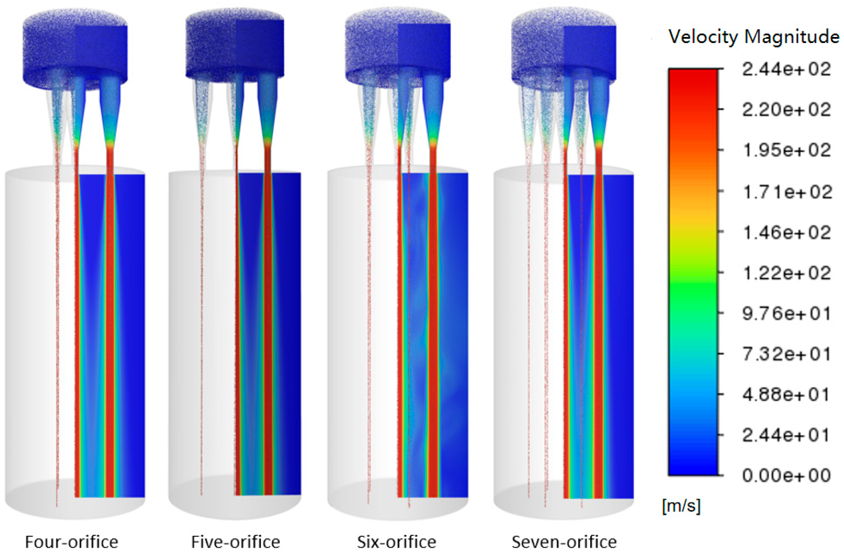
Figure 4: Contours of abrasive particle trajectories and water velocity for nozzles with different orifice counts. The contours and particle trajectories adopt a blue-to-red gradient color scheme, which respectively represent the velocity of water flow and abrasive particles increasing from low to high.
Fig. 5 shows the radial velocity distribution law of the outlet section of the center nozzle and the side nozzle of four kinds of multi-orifice nozzles: four-orifice, five-orifice, six-orifice and seven-orifice. It can be seen from Fig. 5a that the radial velocity at the outlet of the central nozzle presents a quasi-flat-top distribution pattern of overall “high speed and stability in the broad core area and sharp attenuation near the wall”, with only a subtle local velocity depression occurring exactly at the geometric center inside this flat-top platform. The velocity in the core area of the jet is relatively stable and maintained at a high level with strong energy concentration. However, the abrasive is also concentrated in the center of the jet, resulting in a slight local minimum velocity only at the central point rather than an obvious V-shaped velocity trough across the whole core area. This feature is most obvious in the central jet of the four-orifice jet, and the velocity on both sides is high, potentially reflecting that the abrasive of the four-orifice jet is the most concentrated. The maximum velocity of the four-orifice jet is 241.27 m/s, which is slightly higher than those of the five-orifice, six-orifice and seven-orifice nozzles, whose maximum velocities are 235.36 m/s, 237.40 m/s and 239.51 m/s, respectively. It can be seen from Fig. 5b that the velocity distribution of the side nozzle presents certain asymmetric characteristics relative to the central nozzle. The jet velocity of the boundary layer on the side far away from the central nozzle is lower than that on the side close to the central nozzle. This phenomenon is gradually not obvious with the increase of the orifice count. The velocity difference between the two sides is 16.2 m/s for four-orifice, and about 10 m/s for six-orifice and seven-orifice. This is because the inner boundary near the center of the nozzle array is replenished by the entrainment and momentum of the jet from adjacent orifices, and the velocity attenuation in the boundary layer is slower. With the increase of the orifice count, the interaction of the outflow from each orifice tends to be balanced, and this asymmetric characteristic will gradually weaken. The results show that the orifice count directly determines the velocity distribution characteristics and spatial uniformity on the radial line of the outlet section. The abrasive aggregation effect of the center jet is stronger, and the velocity asymmetry of the side jet is more significant under the low orifice count structure. The high orifice count structure can effectively balance the flow state of each nozzle orifice and weaken the distribution distortion of the side nozzle. In practical application, the orifice count can be optimized according to the requirements of rock breaking energy concentration and working face flatness.
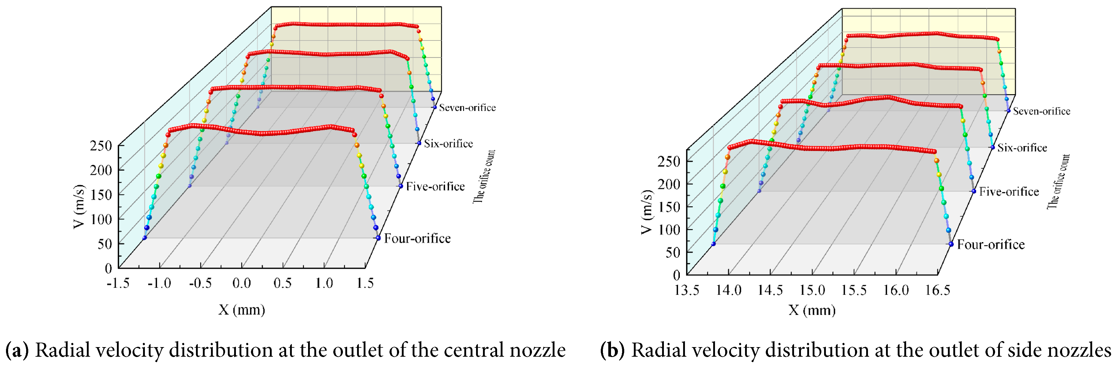
Figure 5: Velocity distribution on the radial line of the nozzle outlet cross-section with different orifice counts (a) the coordinate origin represents the center points of the outlet circle of the central nozzle; (b) the X = 15 mm represent the center points of the outlet circle of the side nozzle.
Fig. 6 shows the velocity distribution along the axis of the central jet and the side jet under the working conditions of the multi-orifice nozzle with different orifice counts, as well as the average velocity variation law of the water phase and the abrasive phase at the jet outlet section. It can be seen from Fig. 6a that the axial velocity along the jet under all working conditions presents typical flow characteristics of low-speed inflow, rapid acceleration in the contraction section, peak velocity near the outlet and slow attenuation in the downstream; The peak velocity of the four-orifice jet outlet is the lowest, and the peak velocity increases significantly when the orifice count increases to 5. The peak velocity of the six-orifice and seven-orifice conditions tends to be stable. Under the condition of low orifice count, the velocity of the side jet is significantly lower than that of the central jet due to the wall shear effect. With the increase of the orifice count, the velocity difference between the two continues to narrow, and the consistency of the flow from each orifice gradually improves.
It can be seen from Fig. 6b that the average velocity at the outlet of the aqueous phase is slightly affected by the orifice count, and is generally stable at about 231 m/s; The average velocity of abrasive phase decreases first and then increases with the increase of the orifice count. The lowest velocity is 199.57 m/s under the condition of five-orifice, and the peak value is 205.80 m/s at the time of seven orifices. The main reason for this phenomenon is the increase of the orifice count. On the one hand, it improves the water flow velocity in the inlet channel, which increases the collision probability between abrasive particles and the wall during the flow separation process, resulting in the loss of local kinetic energy. On the other hand, it improves the uniformity of the flow field in the nozzle, makes the force on particles more uniform, and enhances the continuous traction and acceleration of particles along the direction of high-speed water flow. The two effects work together, so that the average velocity of abrasive outlet first decreases and then increases with the increase of the orifice count. Under the same working condition, the average abrasive velocity of the center jet is slightly higher than that of the side jet, the average velocity of the water phase has no obvious difference. This is mainly because the volume fraction of abrasive particles is only about 1%, and the difference in the average velocity of abrasives is small. The momentum feedback of particles to the water phase has a limited effect on the cross-sectional average velocity. The abrasive velocity is always lower than the water velocity, which reflects the momentum transfer lag characteristics of particle acceleration. In conclusion, the orifice count will significantly change the exit velocity of abrasive particles, the seven-orifice structure is more conducive to improving the abrasive acceleration effect, and the water phase velocity is basically not affected by the number and position of nozzle orifices.
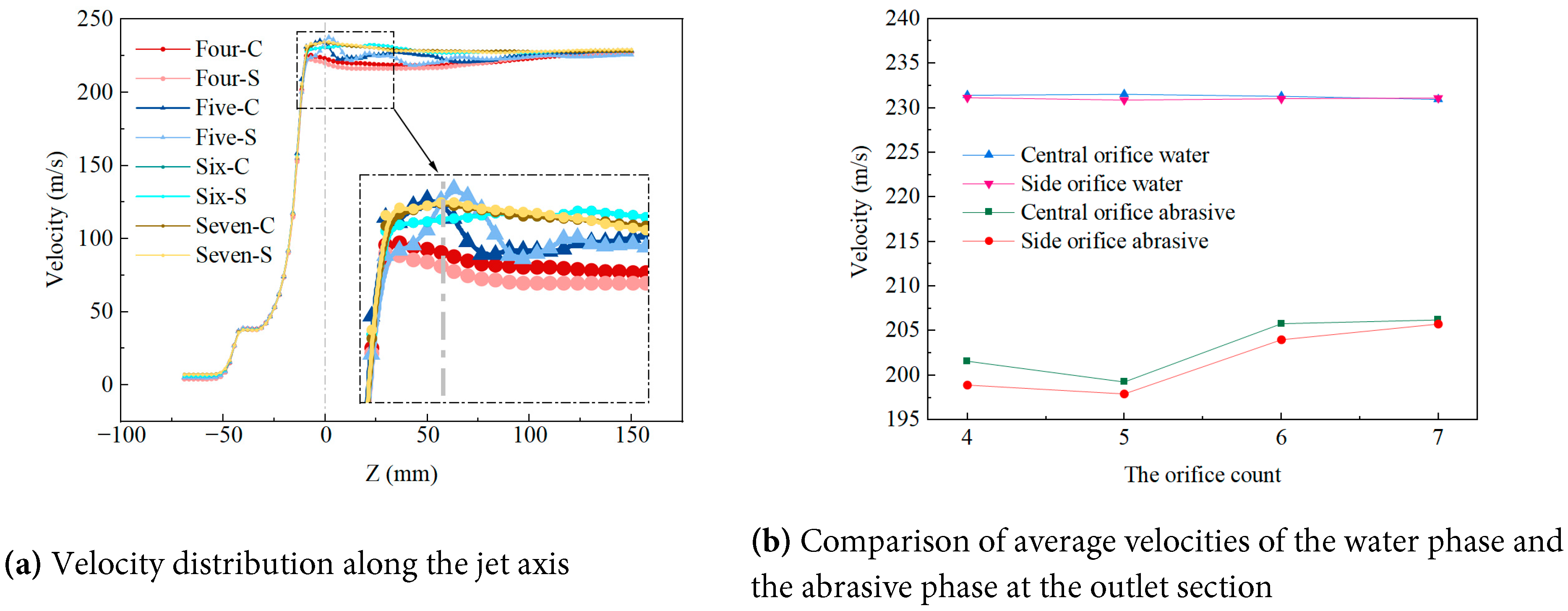
Figure 6: Jet velocity distribution characteristics of nozzles with different orifice counts (a) the numerals in the legend “Number-C(S)” stand for the orifice count, where C(S) refers to central (side) nozzle jets; (b) comparison of average velocities of the water phase and the abrasive phase at the outlet section.
3.2 Spatial Distribution and Discrete Evolution Law of Abrasive Particles at the Outlet Section
Fig. 7 shows the spatial distribution characteristics of abrasive particles at the nozzle outlet section with different orifice counts, including the comparison of two groups of center orifices and side orifices.
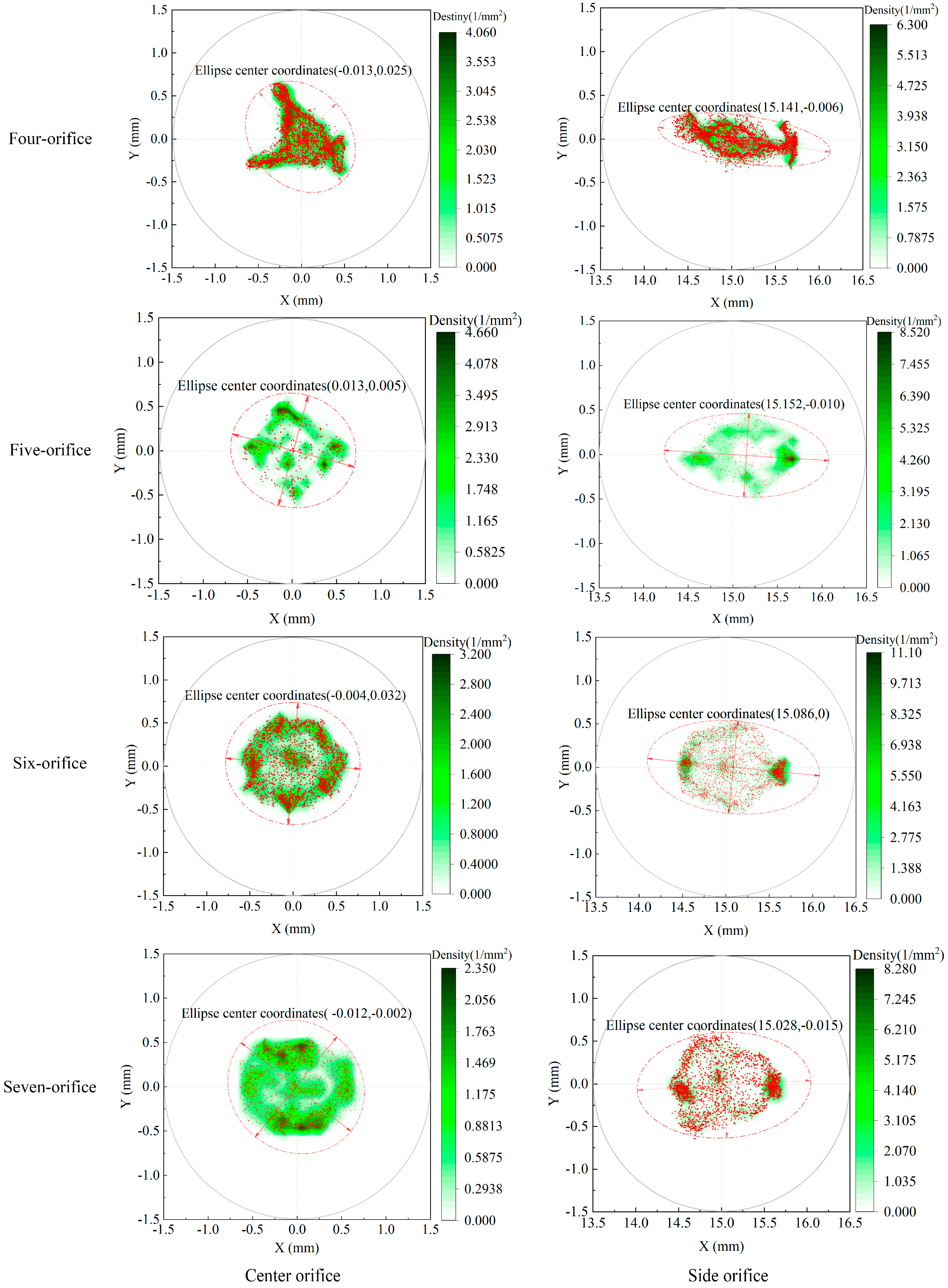
Figure 7: Spatial distribution characteristics of abrasive particles at the outlet section of nozzles with different orifice counts.
After the numerical calculation reaches the steady state, 1000 steps of continuous sampling are taken at the nozzle outlet section to count the impact point of abrasive particles. The probability density distribution of particles is obtained by using two-dimensional kernel density estimation method (the number of X/Y grid points is 30, and the calculation range is 3 mm × 3 mm, which is consistent with the geometric contour of the nozzle orifice with a diameter of 3 mm). Using the Origin software, a 95% confidence ellipse is fitted from the coordinates of all sampled particles. Statistically, this ellipse covers the region containing 95% of all abrasive impact points. Its major-axis length, minor-axis length, area and ellipticity are adopted to quantitatively characterize the dispersion range and anisotropy of the spatial distribution of abrasives. In the figure, the gray solid line circle is the contour of the spray orifice, the red scattered points are the falling points of single particles, and the darker the color of the green cloud image, the higher the probability density of particles. The red dotted line is a 95% confidence ellipse, and each sub-icon note corresponds to the coordinates of the ellipse center, which can reflect the distribution range of 95% particles.
For the center orifice particles, under all working conditions, the abrasive particles are concentrated in the center area of the nozzle orifice, the high-density core area basically coincides with the geometric center of the nozzle orifice, and the particles in the four-orifice condition are in an asymmetric triangular aggregation shape. As the orifice count increases from 4 to 7, the particle distribution profile gradually transits to a nearly circular shape with good symmetry under the seven-orifice condition, and the anisotropy of the circumferential distribution is significantly weakened. From the perspective of kernel density characteristics, the particle aggregation is strong under the condition of low orifice count, and the concentration in the high-density area and the local particle aggregation degree are high; With the increase of the orifice count, the high-density region diffuses evenly around, the radial dispersion of particles increases, and the agglomeration effect is obviously weakened. This is because the total flow area of the nozzle increases with the increase of the orifice count, the throttling effect of the inlet cavity is weakened, the turbulent distribution of the internal flow field is more uniform, the force symmetry of particles in the channel is improved, and the radial fluctuation is enhanced after the outflow, which finally shows the expansion of the distribution range and the improvement of the circumferential uniformity.
The particle distribution at the outlet of the side orifice shows significant anisotropy, and the overall shape is an ellipse elongated along the horizontal direction. The dispersion degree in the short axis direction is much lower than that in the long axis direction, which is the result of the joint action of wall constraint effect and adjacent jet entrainment. Under the condition of four-orifice, the particle height is concentrated in narrow and long strips, and the transverse tensile characteristics are the most significant; As the orifice count increased to 7, the particles expanded significantly along the short axis, the ovality decreased continuously, and the distribution uniformity improved significantly.
Fig. 8 shows the variation of quantitative characteristic parameters extracted based on 95% confidence ellipse with the orifice count. Fig. 8a reflects the evolution law of the long axis and short axis of the confidence ellipse. The long axis of the central ellipse increases slightly and gently with the increase of the orifice count, the short axis increases linearly and continuously, and the difference between the long axis and short axis decreases continuously, which quantitatively confirms the distribution characteristics of the central orifice particles in Fig. 7 from irregular shape to near-circular convergence and the anisotropy continues to weaken. The long axis of the edge ellipse fluctuates from 1.85 mm to 2.03 mm in the whole process, and the overall change is gentle. The short axis increases significantly with the increase of the orifice count. The short axis is only 0.54 mm in four-orifice, and rises to 1.24 mm in seven-orifice. The expansion range of the short axis is much larger than that of the long axis, which is the core reason for the continuous decline of the ellipticity of the edge ellipse.
Fig. 8b shows the evolution law of the area of the confidence ellipse. The area of the confidence ellipse of the central orifice and the side orifice increases monotonously with the orifice count. The area of the confidence ellipse of the central orifice increases from 1.266 mm2 to 1.816 mm2, and the increase of the area of the confidence ellipse of the side orifice is significantly higher than that of the central orifice, from 0.847 mm2 in the case of four-orifice to 1.970 mm2 in the case of seven-orifice, indicating that the orifice count parameter has a stronger effect on the control of the distribution range of the particles in the side orifice. Under the same orifice count, the ellipse area of the center orifice under the conditions of four-orifice, five-orifice and six-orifice is larger than that of the side orifice, and the ellipse area of the side orifice under the conditions of seven-orifice is larger than that of the center orifice.
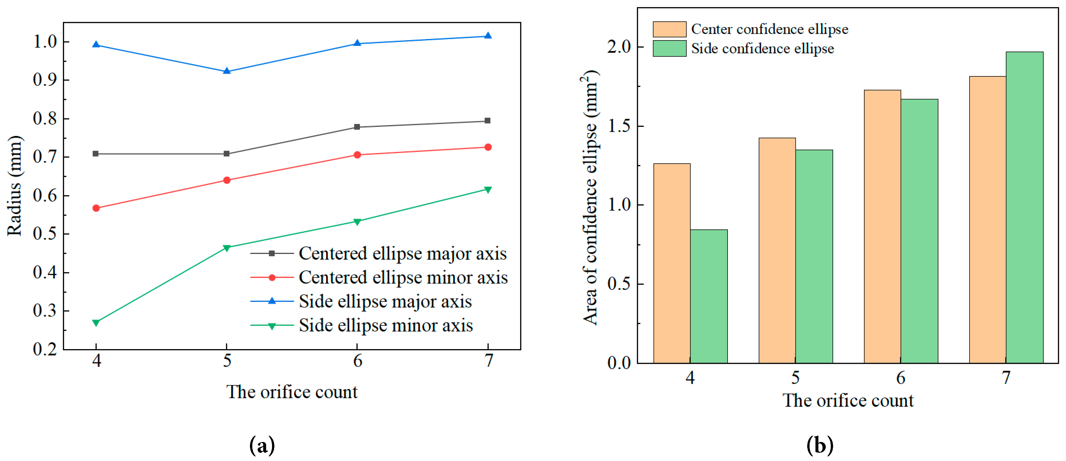
Figure 8: Variation diagram of quantitative characteristic parameters for extracting confidence ellipses of abrasive distribution at nozzle outlet sections with different orifice counts (a) variations in the major and minor axes of the confidence ellipse; (b) area of confidence ellipse and kernel density peak.
To sum up, under the condition of the same orifice count, the particle distribution symmetry of the central orifice is significantly better than that of the side orifice, the shape is more circular, the anisotropy is weaker, and the particles are evenly distributed around the center of the nozzle orifice; The side orifice is affected by the superposition of the wall constraint effect and the adjacent orifice flow field, and its distribution shape is offset and unidirectional elongated, and its uniformity is weaker than that of the central orifice. With the increase of the orifice count, the increase of the confidence ellipse area of the side orifice is larger than that of the center orifice, which indicates that the orifice count parameter has a more significant effect on the control of the dispersion characteristics of the side orifice particles. On the whole, increasing the orifice count can effectively improve the distribution uniformity of abrasive particles at the outlet, and expand the effective range of the jet. The improvement effect of the distribution uniformity of the side orifices is more prominent, which helps to reduce the effect difference between the orifices of the multi-orifice jet, and improve the flatness of the rock breaking face and the overall energy utilization efficiency.
A flatter working face is preferred in precision drilling engineering because it reduces the need for subsequent leveling operations, minimizes stress concentration points that could lead to uncontrolled crack propagation, and improves the accuracy of contour control for the final borehole shape [4,5]. Additionally, a flat fracture surface ensures more uniform load distribution during subsequent support and excavation processes.
3.3 Rock Breaking Performance of MOAWJ and Synergistic Mechanism between Orifices
Fig. 9 shows the temporal and spatial evolution characteristics of rock damage at different times in 50–300 μs during the process of five-orifice AWJ impacting granite, including two observation dimensions of profile and top view, which can systematically reveal the damage development law of rock breaking by multi-orifice jet and the synergistic mechanism between holes. From the section view, it can be seen that the overall rock damage is a conical distribution of “wide at the top and narrow at the bottom”, and the damage degree decreases layer by layer from the impact surface to the deep part of the rock mass. At the initial stage of impact, only an independent shallow damage zone was formed directly below each jet. With the increase of impact time, the damage expanded synchronously along the vertical and radial directions. After 150 μs, the damage superposition occurred in the rock mass between the holes, and a continuous transverse through fracture zone was formed at 200 μs; At the later stage of impact, the lateral propagation rate slowed down, and the damage was mainly caused by deep erosion. The bottom of the fracture zone showed a wave shape corresponding to the jet arrangement.
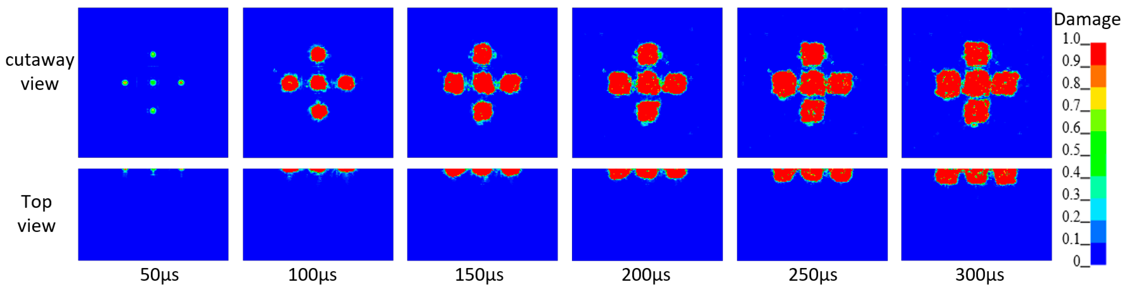
Figure 9: Diagram of rock damage evolution under impact of five-orifice AWJ. Damage (0 ≤ D ≤ 1) denotes the dimensionless damage degree for the granite RHT constitutive model; the color change of the color scale in the figure represents the degree of rock damage, ranging from blue (D = 0, undamaged) to red (D = 1, fully damaged).
From the top view, it can be seen that the rock surface damage presents an evolution trend from discrete to continuous. At 50 μs, there are five independent circular impact damage points, and the proportion of complete damage is very low; As the impact continues, the radial size of each damage zone continues to increase, and the holes gradually close to each other. At 250 μs, it completely penetrates to form a cross-shaped continuous fracture surface; In the later stage, the crushing area increased slowly, the edge was gradually smoothed, and the overall shape was highly consistent with the arrangement of nozzle orifices. Based on the present SPH-FEM simulation results, the whole evolution process can be divided into four stages: initial damage initiation, independent damage propagation, damage breakthrough and fracture, and stable deep erosion. After the high-pressure jet impinges on the rock mass to produce microcracks, the water flow penetrates into the cracks to form the water wedge effect, that is, the concentrated tensile stress at the crack tip continues to expand and extend the cracks. The synergetic effect of stress field superposition between holes and the water wedge is the core driving force for the premature fracture of the rock mass between holes.
It can be seen that the rock breaking by five-orifice AWJ has distinct stage and synergy, and the rock mass between holes can be broken without direct impact under the action of bidirectional shear, which effectively improves the rock breaking area and energy utilization efficiency; At the later stage of impact, the rock breaking mode changed from lateral expansion to deep erosion, and the overall rock breaking efficiency gradually stabilized.
Fig. 10 shows the rock damage distribution of MOAWJ at 300 μs under four working conditions of orifice 4, 5, 6 and 7. It can be seen from the figure that the rock breaking area under four working conditions is in the form of discrete independent impact pits, the damage areas of each hole are separated from each other, there is no obvious penetration effect between holes, the effective rock breaking area is small and the regularity of the fracture surface is poor; Under the condition of five-orifice, the damage area is distributed in a cross shape, and the damage area of the central hole and the peripheral hole is initially connected, but the penetration between the holes is not sufficient, and the edge fragmentation degree is unevenly distributed; Under the condition of six-orifice, the damage areas of each hole are further closer, the rock mass between holes has produced obvious damage superposition, and the continuity and integrity of the fracture surface are significantly improved; Under the seven-orifice working condition, the damage area of each hole is fully penetrated, forming a continuous quasi circular fracture surface as a whole, the complete damage area is evenly distributed, there is no obvious unbroken rock mass between the holes, the effective rock breaking area reaches the maximum in all working conditions, and the flatness of the fracture surface is the best.
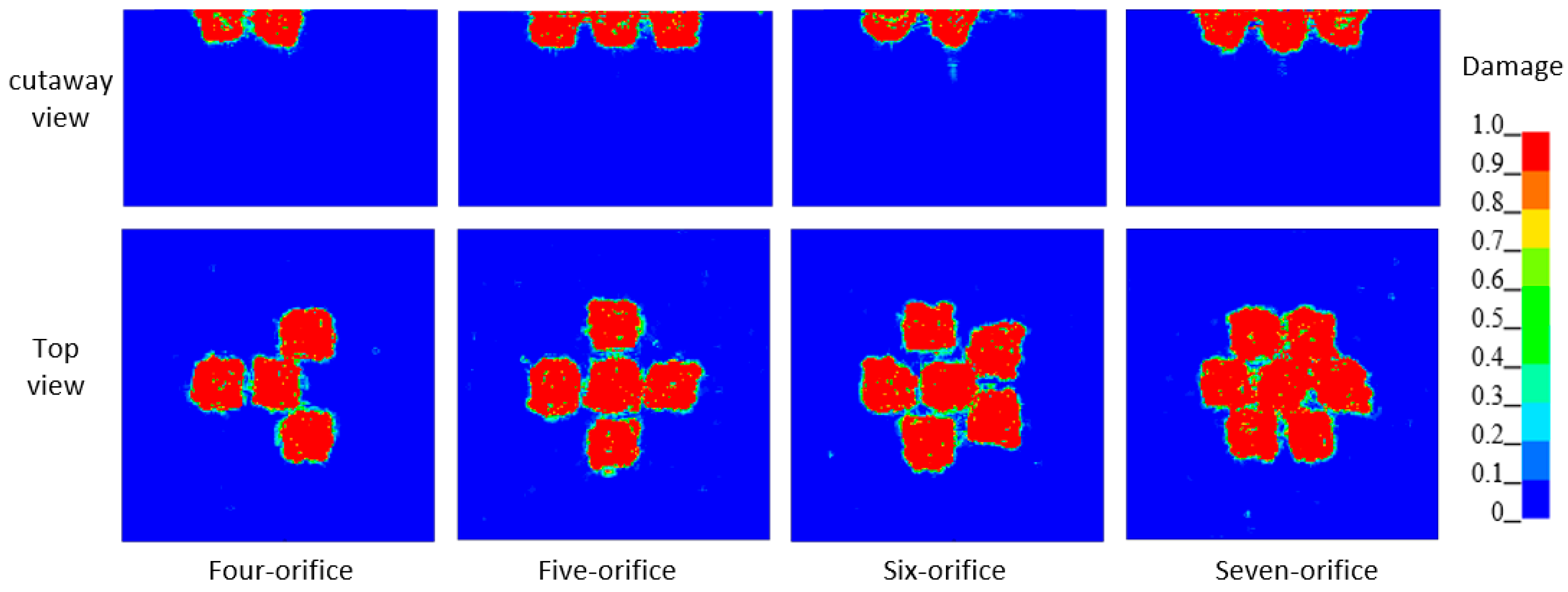
Figure 10: Rock damage diagram of rock breaking by MOAWJ under different orifice counts (300 μs). Damage (0 ≤ D ≤ 1) denotes the dimensionless damage degree for the granite RHT constitutive model.
The above rock breaking characteristics are highly consistent with the velocity distribution and abrasive particle distribution in the jet. Under the condition of low orifice count, the total flow area of the nozzle is small, the interaction of jets in each hole is weak, and the rock between holes is difficult to be impacted by the synergistic impact, so the rock breaking is mainly characterized by independent deep pits; With the increase of the orifice count, the flow uniformity of each jet orifice is improved, the distribution range of abrasive particles is expanded and the discreteness is enhanced, and the stress field of adjacent jets and the water wedge effect are fully superimposed, so that the rock between holes is synergistically broken under the action of two-way shear, and the damage can be generated without direct impact of jets, which ultimately promotes the transformation of rock breaking mode from “depth dominated” to “area dominated”. It can be seen that the orifice count can effectively control the rock breaking mode and effect of MOAWJ, and increasing the orifice count can significantly strengthen the synergistic breaking effect between holes, expand the effective rock breaking area and improve the flatness of the working face.
The shift from depth-dominated to area-dominated failure mode is essentially governed by the coupling of jet dynamic uniformity and inter-orifice synergistic effect. At low orifice count, the prominent inlet throttling effect causes uneven outflow velocity among orifices and highly concentrated radial distribution of abrasive particles. Most of the jet impact energy is transmitted vertically downward along the axis of each single orifice, resulting in independent deep erosion pits with limited lateral expansion, which corresponds to the depth-dominated breaking pattern. As orifice count increases, the weakened throttling effect improves the consistency of velocity and energy output across all orifices, and the expanded abrasive distribution range enlarges the effective impact radius of each jet. This enables more sufficient superposition of stress fields induced by adjacent jets in the inter-orifice region. Meanwhile, water penetrating into the initial microcracks further amplifies the tensile stress at crack tips via the water wedge effect, accelerating crack propagation and coalescence. Under the combined action of bidirectional shear stress and water wedge splitting, the inter-orifice rock mass can be effectively fractured even without direct high-energy jet impact. This mechanism continuously expands the lateral coverage of rock damage and ultimately drives the overall failure mode to transform from vertical deep erosion to lateral continuous fragmentation, namely the area-dominated pattern.
Existing experimental studies can provide indirect support for the above evolution characteristics. For instance, Bi et al. [39] verified through rock-breaking experiments that multi-orifice jets can drill large-scale regular holes, and the flatness of the hole bottom profile improves significantly with the increase of orifice count, which matches the transition trend from discrete independent impact pits to a continuous smooth fracture surface observed in the simulation. Targeted laboratory tests will be carried out in subsequent work to verify and calibrate the numerical simulation conclusions.
Fig. 11 shows the dynamic evolution law of rock breaking area and rock breaking volume of four kinds of MOAWJ with orifices 4, 5, 6 and 7 in the impact process of 0 to 300 μs. The rock breaking data are collected by the volume measurement plug-in of LS-Prepost software: the rock breaking volume is directly obtained by monitoring the volume change of the whole rock model; The broken rock area is indirectly converted by measuring the total volume change of rock units within 2 mm of the rock surface. It can be seen from Fig. 11a that the rock breaking area under all working conditions shows a significant stage growth feature: 0 to 50 μs is the initial damage initiation stage, the jet only causes micro damage to the rock surface, and the rock breaking area is very small, less than 1 mm2; After 50 μs, with the continuous erosion of the jet and the penetration of the damage between the holes, the rock breaking area entered a rapid expansion stage, and the growth rate gradually stabilized. When the impact reaches 300 μs, the total rock breaking areas of four-orifice, five-orifice, six-orifice and seven-orifice are 484.47 mm2, 652.20 mm2, 787.92 mm2 and 928.40 mm2, respectively, which show a monotonic increasing trend with the increase of the orifice count; Converted into the average rock breaking area of a single orifice, they are 121.12 mm2, 130.44 mm2, 131.32 mm2 and 132.63 mm2, respectively. The effective range of a single orifice increases slightly with the increase of the orifice count, reflecting the gain effect of the synergistic crushing between holes on the action area.
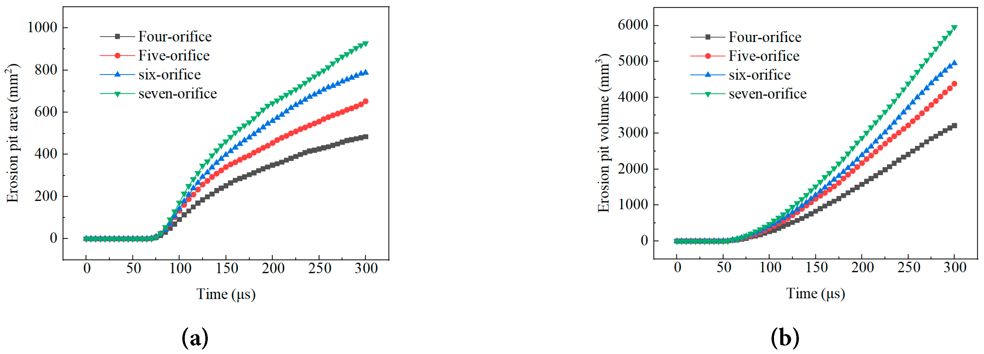
Figure 11: Curve graph of rock breaking area and volume of MOAWJ under different orifice counts (a) characteristics of rock breaking area; (b) characteristics of rock breaking volume.
It can be seen from Fig. 11b that the evolution trend of rock breaking volume presents a change law of “slow start, rapid growth and stable improvement”, which is because the jet kinetic energy is mainly used to overcome the rock strength and drive the microcrack propagation in the initial stage. At 300 μs, the total rock breaking volume under four-orifice, five-orifice, six-orifice and seven-orifice conditions is 3215.93 mm3, 4384.81 mm3, 4951.91 mm3 and 5960.22 mm3 respectively, and the total rock breaking volume under seven-orifice conditions is 85.3% higher than that under four-orifice conditions; The average rock breaking volume of a single orifice is 803.98 mm3, 876.96 mm3, 825.32 mm3 and 851.46 mm3, respectively. The vertical erosion capacity of a single orifice under the five-orifice condition is the strongest. After the orifice count further increases, the average rock breaking volume of a single orifice slightly decreases. The increase in the total rock breaking volume is mainly due to the superposition contribution of the increase in the number of jet action points and the collaborative breaking between orifices.
The difference of the total rock breaking efficiency is due to the dual mechanism: on the one hand, the increase of the orifice count directly expands the total action area of the jet and improves the overall crushing scale; On the other hand, the superposition of the stress field of adjacent jets and the action of water wedge make the rock mass between orifices break synergistically, and damage can occur without direct impact of jets. Therefore, the average rock breaking index of a single orifice does not decrease with the increase of the orifice count, but remains stable and slightly improves.
In conclusion, the orifice count is the core parameter to control the rock breaking effect of MOAWJ, and increasing the orifice count can significantly improve the total rock breaking area and total rock breaking volume; The overall rock breaking scale and efficiency of the seven-orifice condition are the best, which is suitable for the large-area flat rock breaking scene. The single orifice erosion ability of the five-orifice condition is outstanding, which is more suitable for the engineering demand of directional deep rock breaking.
In this paper, based on the precise drilling engineering of pumped storage power station, using the numerical simulation method of VOF-DPM and SPH-FEM coupling, the influence of four-orifice to seven-orifice nozzles on the dynamic characteristics and rock-breaking performance of MOAWJ is systematically studied, and the regulation mechanism of orifice count parameters and the mechanism of collaborative rock breaking are clarified.
Increasing the orifice count can optimize the flow field and alleviate particle agglomeration; The average velocity of the water phase exit is basically stable, and the average velocity of the abrasive phase is the lowest in the five-orifice and the highest in the seven-orifice;
Increasing the orifice count expands the distribution range of particles in the center and side nozzles, weakens the distribution anisotropy, and improves the circumferential uniformity and symmetry, especially for the uniformity of particle distribution in the side nozzle;
The rock breaking by MOAWJ can be divided into four stages: initial damage initiation, independent damage propagation, damage penetration and fracture, and stable depth erosion. The synergistic breaking is realized by the shear stress between orifices and the water wedge effect, so as to improve the rock breaking efficiency;
With the increase of the orifice count, the rock breaking has changed from deep erosion to large-area erosion. The comprehensive rock breaking performance of seven orifices is the best, which is suitable for large-area construction.
Acknowledgement:
Funding Statement: This research was funded by the National Natural Science Foundation of China (Grant No. 52506041) and Professional Degree Postgraduates’ “Practice, Innovation and Entrepreneurship Ability Improvement Program” of Changsha University of Science & Technology (CLSJCX25052).
Author Contributions: The authors confirm contribution to the paper as follows: conceptualization, Shurong Feng, Dongping Zeng; methodology, Fada Zhou; software, Fada Zhou; validation, Yanan Zhao and Hao Liu; investigation, Dongping Zeng and Fada Zhou; writing—original draft preparation, Dongping Zeng and Fada Zhou; writing—review and editing, Dongping Zeng and Fada Zhou; supervision, Shurong Feng; funding acquisition, Shurong Feng. All authors reviewed and approved the final version of the manuscript.
Availability of Data and Materials: The authors confirm that the data supporting the findings of this study are available within the article.
Ethics Approval: Not applicable.
Conflicts of Interest: The authors declare no conflicts of interest.
Nomenclature
The following abbreviations are used in this manuscript:
| ρ | Density |
| t | Time |
| u | Average velocity |
| α | Volume fraction |
| U | Volume flow |
| xi and xj | Spatial coordinate components |
| μ | Viscosity |
| F | Forces |
| g | Gravitational acceleration |
| σ | Surface tension coefficient |
| κ | Interface curvature |
| δs | Dirac delta function at the interface |
| ni | Unit normal vector component to the interface |
| ΔV | Control-volume size |
| k | Turbulent kinetic energy |
| ε | Turbulent dissipation rate |
| Gk | Turbulent kinetic energy generation term |
| C1ε and C2ε | Empirical model constants |
| αk and αε | Reciprocal of the effective Prandtl number corresponding to the turbulent kinetic energy k and turbulent dissipation rate ε transport process, respectively |
| Cμ | Model constant |
| FD | Drag coefficient acting on particles per unit mass |
| ALE | Arbitrary Lagrangian-Eulerian |
| AWJ | Abrasive water jet |
| DPM | Discrete Phase Model |
| MOAWJ | Multi-orifice abrasive water jet |
| PSH | Pumped storage hydropower |
| RHT | Riedel-Hiermaier-Thoma |
| RNG k-ε | Renormalization Group k-epsilon turbulence model |
| SPH-FEM | Smoothed particle hydrodynamics-finite element method |
| VOF | Volume of Fluid |
| VOF-DPM | Volume of fluid-discrete phase model |
References
1. Lin M , Shen J , Guo X , Ge L , Lü Q . Comparison of pumping station and electrochemical energy storage enhancement mode for hydro-wind-photovoltaic hybrid systems. Energy. 2025; 315: 134362. doi:10.1016/j.energy.2025.134362. [Google Scholar] [CrossRef]
2. Tang H , Li R , Song T , Ju S . Short-term optimal scheduling and comprehensive assessment of hydro-photovoltaic-wind systems augmented with hybrid pumped storage hydropower plants and diversified energy storage configurations. Appl Energy. 2025; 389: 125787. doi:10.1016/j.apenergy.2025.125787. [Google Scholar] [CrossRef]
3. Guo A , Dai J , Chang J , Wang Y , Deng X , Wang X . Coordinated peak shaving of open-loop pumped-storage and conventional hydropower plants: multiple operation modes, optimal operating boundaries and associated impacts. Energy Convers Manag. 2025; 345: 120386. doi:10.1016/j.enconman.2025.120386. [Google Scholar] [CrossRef]
4. Colas E , Klopries EM , Tian D , Kroll M , Selzner M , Bruecker C , et al. Overview of converting abandoned coal mines to underground pumped storage systems: focus on the underground reservoir. J Energy Storage. 2023; 73: 109153. doi:10.1016/j.est.2023.109153. [Google Scholar] [CrossRef]
5. Zhang C , Liu X , Fang X , Yang J , Xie Y , Zhou W . Challenges of shaft drilling in broken rock masses with a large raise boring machine in confined underground space: a case study. Tunn Undergr Space Technol. 2024; 147: 105694. doi:10.1016/j.tust.2024.105694. [Google Scholar] [CrossRef]
6. Wang H , Wu Y , Qu X , Wang W , Liu Y , Xie WC . Experimental and numerical investigations on failure process and permeability evolution of weathered granite under hydro-mechanical coupling. Int J Rock Mech Min Sci. 2025; 191: 106117. doi:10.1016/j.ijrmms.2025.106117. [Google Scholar] [CrossRef]
7. Zheng J , Wu Z , Nie J , Lei L , Zhou Z , Li J . From rock-boring organisms to tunnel boring machines: a new rock breaking technology by bioinspiration. Biosurf Biotribol. 2021; 7( 4): 233– 8. doi:10.1049/bsb2.12025. [Google Scholar] [CrossRef]
8. Shangguan J , Ge Z , Zhou Z , Zhang X , Liu L , Li Z . Experimental study on dynamic deformation and breaking mechanism of high-temperature hard rock cutting by abrasive water jet. Int J Rock Mech Min Sci. 2024; 180: 105797. doi:10.1016/j.ijrmms.2024.105797. [Google Scholar] [CrossRef]
9. Li H , Li J , Guo C , Liu P , Wang H , Huang Z . Numerical investigation into the abrasive particle movement characteristics inside the swirling impeller nozzle based on the coupled SPH-FEM method. Powder Technol. 2024; 436: 119458. doi:10.1016/j.powtec.2024.119458. [Google Scholar] [CrossRef]
10. Nair A , Adam Khan M , Sivakumar M , Selvaganesh RM , Sushanth J , Sachin M . Geometric characteristics analysis of hole making through abrasive water jet drilling. Mater Today Proc. 2021; 39: 338– 47. doi:10.1016/j.matpr.2020.07.430. [Google Scholar] [CrossRef]
11. Liu S , Cui Y , Chen Y , Guo C . Numerical research on rock breaking by abrasive water jet-pick under confining pressure. Int J Rock Mech Min Sci. 2019; 120: 41– 9. doi:10.1016/j.ijrmms.2019.06.007. [Google Scholar] [CrossRef]
12. Zhang Y , Hu D , Liu Y . The effect of polymer-assisted abrasive jets on the surface quality of cut marbles. Fluid Dyn Mater Process. 2025; 21( 7): 1641– 55. doi:10.32604/fdmp.2025.065820. [Google Scholar] [CrossRef]
13. Wang Y , Wang Y , Wang J , Zhang C , Meng F , Zhang L , et al. Influence of nozzle geometry and operating parameters on high-pressure water jets. Fluid Dyn Mater Process. 2025; 21( 11): 2761– 77. doi:10.32604/fdmp.2025.072236. [Google Scholar] [CrossRef]
14. Li Y , Peng J , Zhang G , Yang Z , Li K . Study on perforation performance of abrasive water jet enhanced by percussive drilling. J Petrol Sci Eng. 2020; 192: 107259. doi:10.1016/j.petrol.2020.107259. [Google Scholar] [CrossRef]
15. Chi H , Li G , Liao H , Tian S , Song X . Effects of parameters of self-propelled multi-orifice nozzle on drilling capability of water jet drilling technology. Int J Rock Mech Min Sci. 2016; 86: 23– 8. doi:10.1016/j.ijrmms.2016.03.017. [Google Scholar] [CrossRef]
16. Bi G , Wang X , Li M , Wu J , Han F , Yuan P , et al. Structural design and flow field characteristics analysis of a new spin-on multi-hole jet drill bit for radial horizontal wells. Geoenergy Sci Eng. 2023; 230: 212173. doi:10.1016/j.geoen.2023.212173. [Google Scholar] [CrossRef]
17. Ba Q , Liu Y , Zhang Z , Xiong W , Shen K . Analysis of the flow field characteristics associated with the dynamic rock breaking process induced by a multi-hole combined external rotary bit. Fluid Dyn Mater Process. 2021; 17( 4): 697– 710. doi:10.32604/fdmp.2021.014762. [Google Scholar] [CrossRef]
18. Lu Y , Zhou Z , Ge Z , Zhang X , Li Q . Research on and design of a self-propelled nozzle for the tree-type drilling technique in underground coal mines. Energies. 2015; 8( 12): 14260– 71. doi:10.3390/en81212426. [Google Scholar] [CrossRef]
19. Song X , Lyu Z , Cui L , Li G , Ji G , Pang Z . Comparison of numerical analysis on the downhole flow field for multi-orifice hydrothermal jet drilling technology for geothermal wells. Geothermics. 2017; 70: 314– 23. doi:10.1016/j.geothermics.2017.07.004. [Google Scholar] [CrossRef]
20. Song X , Lv Z , Li G , Hu X , Shi Y . Numerical analysis of characteristics of multi-orifice nozzle hydrothermal jet impact flow field and heat transfer. J Nat Gas Sci Eng. 2016; 35: 79– 88. doi:10.1016/j.jngse.2016.08.013. [Google Scholar] [CrossRef]
21. Zhu X , Wu D , Yang Z . Experimental study on drilling laws by self-advancing and multi-hole jet bit. Fluid Mach. 2016; 44( 2): 12– 6. (In Chinese). doi:10.3969/j.issn.1005-0329.2016.02.003. [Google Scholar] [CrossRef]
22. Lu Y , Xiao S , Ge Z , Zhou Z , Ling Y , Wang L . Experimental study on rock-breaking performance of water jets generated by self-rotatory bit and rock failure mechanism. Powder Technol. 2019; 346: 203– 16. doi:10.1016/j.powtec.2019.01.078. [Google Scholar] [CrossRef]
23. Liu Y , Ba Q , He L , Shen K , Xiong W . Study on the rock-breaking effect of water jets generated by self-rotatory multinozzle drilling bit. Energy Sci Eng. 2020; 8( 7): 2457– 70. doi:10.1002/ese3.679. [Google Scholar] [CrossRef]
24. Ge Z , Deng K , Zhou Z , Yang M , Chai C . Fracture characteristics of coal jointly impacted by multiple jets. Eng Fract Mech. 2020; 235: 107171. doi:10.1016/j.engfracmech.2020.107171. [Google Scholar] [CrossRef]
25. Lu Y , Xiao S , Ge Z , Zhou Z , Deng K . Rock-breaking properties of multi-nozzle bits for tree-type drilling in underground coal mines. Energies. 2016; 9( 4): 249. doi:10.3390/en9040249. [Google Scholar] [CrossRef]
26. Chi H , Li G , Huang Z , Tian S , Song X . Maximum drillable length of the radial horizontal micro-hole drilled with multiple high-pressure water jets. J Nat Gas Sci Eng. 2015; 26: 1042– 9. doi:10.1016/j.jngse.2015.07.044. [Google Scholar] [CrossRef]
27. Ma L , Huang C , Xie Y , Jiang J , Tufa KY , Hui R , et al. Modeling of erodent particle trajectories in slurry flow. Wear. 2015; 334: 49– 55. doi:10.1016/j.wear.2015.04.013. [Google Scholar] [CrossRef]
28. Hwang HJ , Cha Y , Kang SJ , Cho GC . Semi-empirical model for abrasive particle velocity prediction in abrasive waterjet based on momentum transfer efficiency. Comput Part Mech. 2024; 11( 6): 2701– 13. doi:10.1007/s40571-024-00747-6. [Google Scholar] [CrossRef]
29. Long X , Ruan X , Liu Q , Chen Z , Xue S , Wu Z . Numerical investigation on the internal flow and the particle movement in the abrasive waterjet nozzle. Powder Technol. 2017; 314: 635– 40. doi:10.1016/j.powtec.2016.09.089. [Google Scholar] [CrossRef]
30. Issakhov A , Sabyrkulova A , Abylkassymova A . CFD modeling the disintegration of an intranasal spray jet in the human upper respiratory tract using the VOF-to-DPM model. Commun Nonlinear Sci Numer Simul. 2025; 151: 109093. doi:10.1016/j.cnsns.2025.109093. [Google Scholar] [CrossRef]
31. Hu X , Zhou S , He C , Mao Y , Zhang H , Wu D , et al. Failure mechanisms of sand-laden water jet nozzles: coupled particle deposition and particle-induced erosion controlled by outlet cross-section geometry. Eng Fail Anal. 2026; 197: 111123. doi:10.1016/j.engfailanal.2026.111123. [Google Scholar] [CrossRef]
32. Lv Z , Hou R , Tian Y , Huang C , Zhu H . Investigation on flow field of ultrasonic-assisted abrasive waterjet using CFD with discrete phase model. Int J Adv Manuf Technol. 2018; 96( 1): 963– 72. doi:10.1007/s00170-018-1635-4. [Google Scholar] [CrossRef]
33. ANSYS Inc. Ansys fluent user’s guide, release 2023 R1. Canonsburg, PA, USA: ANSYS Inc.; 2023. doi:10.1002/CPRT.31503. [Google Scholar] [CrossRef]
34. Tang J , Zhang J , Liu W , Chen C , Zhang H , Cui J . Two-way coupled CFD-DEM model of a pre-mixed abrasive water jet and its application to the investigation of abrasive motion characteristics. Powder Technol. 2024; 438: 119650. doi:10.1016/j.powtec.2024.119650. [Google Scholar] [CrossRef]
35. Li M , Wei Z , Hou Y , Li D , Wang X , Wu S , et al. The study of abrasive water jet side cutting process using the coupled FEM-SPH method. Int J Adv Manuf Technol. 2026; 142( 3): 1679– 94. doi:10.1007/s00170-025-17147-6. [Google Scholar] [CrossRef]
36. Li H , Li J , Huang Z , Kuru E , Guo C , Hu J . Numerical investigation of abrasive water jet rock damage characteristics that considers the shape, the interaction and the fragmentation of abrasive particles. Rock Mech Rock Eng. 2025; 58( 2): 2105– 31. doi:10.1007/s00603-024-04297-4. [Google Scholar] [CrossRef]
37. Li H , Li J , Huang Z , Guo C , Wang H , Li W . Numerical investigation of abrasive water jet impact force characteristics by using the coupled SPH-FEM method: considering the shape, the interaction and the fragmentation of abrasive particles. Powder Technol. 2025; 465: 121287. doi:10.1016/j.powtec.2025.121287. [Google Scholar] [CrossRef]
38. Li H , Wang F , Zhang J , Liang R , Wen Y . Sensitivity analysis and determination of some parameters of the rock RHT model. Chin J High Press Phys. 2025; 39( 6): 66– 76. (In Chinese). doi:10.11858/gywlxb.20240965. [Google Scholar] [CrossRef]
39. Bi G , Li G , Qu Z , Niu J , Huang Z , Xi Z , et al. Rock breaking efficiency of the self-propelled swirling jet bit. Acta Pet Sin. 2016; 37( 5): 680– 7. (In Chinese). doi:10.7623/syxb201605012. [Google Scholar] [CrossRef]
Cite This Article
 Copyright © 2026 The Author(s). Published by Tech Science Press.
This work is licensed under a Creative Commons Attribution 4.0 International License , which permits unrestricted use, distribution, and reproduction in any medium, provided the original work is properly cited.
 Downloads
 Citation Tools
