
 Submit a Paper
 Propose a Special lssue
 Open Access
ARTICLE
Numerical Simulation of Heat Transfer of High-Temperature Slag Flow Inside the Blast Furnace Slag Trench
School of Energy and Environmental Engineering, University of Science and Technology Beijing, Beijing, 100083, China
* Corresponding Author: Fuyong Su. Email:
Frontiers in Heat and Mass Transfer 2023, 21, 281-292. https://doi.org/10.32604/fhmt.2023.043221
Received 26 June 2023; Accepted 10 August 2023; Issue published 30 November 2023
 View Full Text
 Download PDF
Abstract
To investigate the flow and heat transfer process of blast furnace slag through the slag trench after the slag is discharged, a three-dimensional physical model is established and simulated according to the actual size of the slag trench and the physical properties of the high-temperature slag. The temperature fied and flow field distribution of the high-temperature slag liquid inside the slag trench is obtained by numerical simulation under different working conditions, and the effects of operating conditions such as slag trench inclination, high-temperature slag inlet flow rate, and inlet temperature are investigated. The results show that the flow rate of high-temperature slag is related to the slope of the slag trench, the greater the slope of the slag trench, the higher the flow rate of high-temperature slag, in which the highest average speed can reach 2.23 m/s when the slope is 8%; changing the inlet flow rate, flowing through the slag trench, the high-temperature slag reaches the highest flow rate at the same position, the overall flow rate changes tend to rise first and then decrease, and the greater the inlet flow rate, the higher the temperature change of high-temperature slag. The higher the inlet flow rate, the higher the temperature change of high-temperature slag, the higher the temperature of high-temperature slag out of the slag trench; the higher the inlet temperature, the higher the overall flow rate of high-temperature slag, and the position of the highest flow rate is relatively backward.Keywords
To investigate the flow and heat transfer process of blast furnace slag through the slag trench after the slag is discharged, a three-dimensional physical model is established and simulated according to the actual size of the slag trench and the physical properties of the high-temperature slag. The temperature field and flow field distribution of the high-temperature slag liquid inside the slag trench is obtained by numerical simulation under different working conditions, and the effects of operating conditions such as slag trench inclination, high-temperature slag inlet flow rate, and inlet temperature are investigated. The results show that the flow rate of high-temperature slag is related to the slope of the slag trench. The greater the slope of the slag trench, the higher the flow rate of high-temperature slag, in which the highest average speed can reach 2.23 m/s when the slope is 8%; changing the inlet flow rate, flowing through the slag trench, the high-temperature slag reaches the highest flow rate at the same position, the overall flow rate changes tend to rise first and then decrease, and the greater the inlet flow rate, the higher the temperature change of high-temperature slag. The higher the inlet flow rate, the higher the temperature change of high-temperature slag, the higher the temperature of high-temperature slag out of the slag trench; the higher the inlet temperature, the higher the overall flow rate of high-temperature slag, and the position of the highest flow rate is relatively backward.
High energy consumption is a typical characteristic of the iron and steel industry, and how to further reduce energy consumption is one of the key points of energy conservation in China [1], where blast furnace slag is one of the main by-products produced in the process of steel production, and the slag temperature of blast furnace slag is high, which can reach 1723~1923 K. On average, 350 kg of blast furnace slag [2,3] are produced for each meal of pig iron, so the production of blast furnace slag is very large. And because of its own high temperature, blast furnace slag is rich in heat at the same time. Previously, the domestic and foreign ways to utilize blast furnace slag was the water quenching method [4]. This method only recycles the resources of blast furnace slag. At present, except for a few cities in the north of the winter water quenching slag hot water used for residential heating [5], blast furnace slag contains sensible heat and basically has not been recycled, and a large amount of water resources are wasted. Waste heat recovery from high-temperature slag is the latest potential way to significantly reduce energy consumption and carbon dioxide emissions in the iron and steel industry [6,7] and can improve the heat recovery rate [3,8,9]. In addition to wet recycling of blast furnace slag, there are also dry recycling methods. The blast furnace slag dry treatment process first emerged in the mid-twentieth century in Europe. In the seventies, Japan also conducted in-depth research on dry granulation of blast furnace slag treatment process, and at the beginning of the twenty-first century, Australia’s CSIRO likewise reported a similar work [10]. Dry granulation and recycling [11,12] to treat blast furnace slag are rotary cup granulation [13], rotary cylinder granulation [14,15], air quenching granulation [16,17] and so on.
For the heat transfer of blast furnace slag has been studied by several scholars previously, Qiu [18] and others based on the CFD-DEM coupling method to analyze the numerical simulation of the waste heat recovery process of blast furnace slag mixed with multiple particle sizes and the results show that the two different particle sizes of blast furnace slag mixed with the lowest exit temperature, the highest gas exit temperature, and the best heat transfer effect after the heat exchange. Gao et al. [19] established a two-dimensional symmetric model to describe the crystallization behavior of blast furnace slag droplets by enthalpy method. The results showed the changing law of local cooling rate and crystalline phase distribution. The relationship equations of average cooling rate and final crystalline phase content with dimensionless parameters were established for predicting the slag quality under different operating conditions. Xing et al. [20] established a physical and mathematical model for the solidification of spherical steel slag with single particles, examined the influence of slag particle diameter on the effect of particle heat transfer, and analyzed the heat transfer of blast furnace slag, which provided some guidance for the subsequent granulation system involved. Wang [21] and others conducted experiments on granulated slag, taking into account factors such as the yield and performance of granulated steel slag, the optimal dosing of blast furnace slag is about 15%, and explored the heat exchange effect of high-temperature slag particles in the gas quenching state. Feng [22] and others simulated and analyzed the process of slag collision with phase change and heat transfer in flight based on the dry granulation heat recovery technology of blast furnace slag. Xiang [23] and others established a numerical model for the process of molten blast furnace slag droplets impacting the wall with coupled phase change heat transfer and crystallization behavior and simulated the dynamic behavior, heat transfer, and crystallization characteristics of molten blast furnace slag droplets impacting the wall with different droplet diameters, impact velocities, and wall surface conditions. Gu [24] and others investigated the changes in the precipitation phase and specific heat of air-quenched steel slag (AQSS) particles during continuous cooling using FactSage and thermogravimetric analysis differential scanning calorimetry. The cooling and solidification processes of molten AQSS particles were simulated by Fluent. The results showed that the precipitation of Ca2Fe2O5 led to the largest change in specific heat during the cooling process of molten AQSS particles. Zhang et al. [25] investigated by numerical simulation how to improve the efficiency and effectiveness of mechanical stirring on the modification of hot slag, and the dispersion of the final modifier particles depended on the axial circulating velocity and turbulent kinetic energy on the hot slag surface. The dynamic steady state of particle motion in each region can be obtained within 8 s by mechanical stirring. Yang [26] used MFiX software to numerically simulate the flow and heat transfer process of blast furnace slag particles around anisotropic heat exchanger tubes to study the heat transfer process of blast furnace slag particles around anisotropic tubes, and the results showed that when the heat exchanger tube bundles were arranged in forked rows, the particles flowed better, which strengthened the perturbation between the particles, and also the temperature distribution of the particles was more uniform.
But the current research is limited to blast furnace slag discharge slag ditch after the treatment. The blast furnace discharge flow through the slag ditch part of the research is still lacking. This paper for high-temperature slag discharge flows through the slag ditch part of the research. In this study, a three-dimensional slag trench model was constructed to simulate the flow of high-temperature slag from the slag outlet into the internal slag trench and the heat transfer process, combined with the standard k-ε turbulence model for numerical simulation. The velocity field, as well as the temperature field, were analyzed, and the effects of slag trench inclination, incoming high-temperature slag flow rate, and incoming high-temperature slag temperature on the heat transfer and flow characteristics of high-temperature slag inside the slag trench were discussed. The intention is to explore clearly after the blast furnace slag discharge, flow through the slag ditch part of the high-temperature slag flow and heat transfer, to explore the slag ditch high-temperature slag flow field as well as the distribution of the temperature field, with the aim of the subsequent establishment of a digital slag ditch to provide a theoretical basis for providing the appropriate guidance.
2.1 Physical Model and Fixed Solution Conditions
The actual slag trench is shown in Fig. 1a. In real life, the high-temperature slag flows through the slag trench to the next step to continue to use. Physical modeling is shown in Fig. 1b. This paper reasonably simplifies the operation; the inlet is the velocity inlet, and the outlet is the outflow boundary. Grid division is as shown in Fig. 1c, this paper uses tetrahedral mesh to divide the whole model. The final grid number is 386880, and the number of nodes is 1638707.
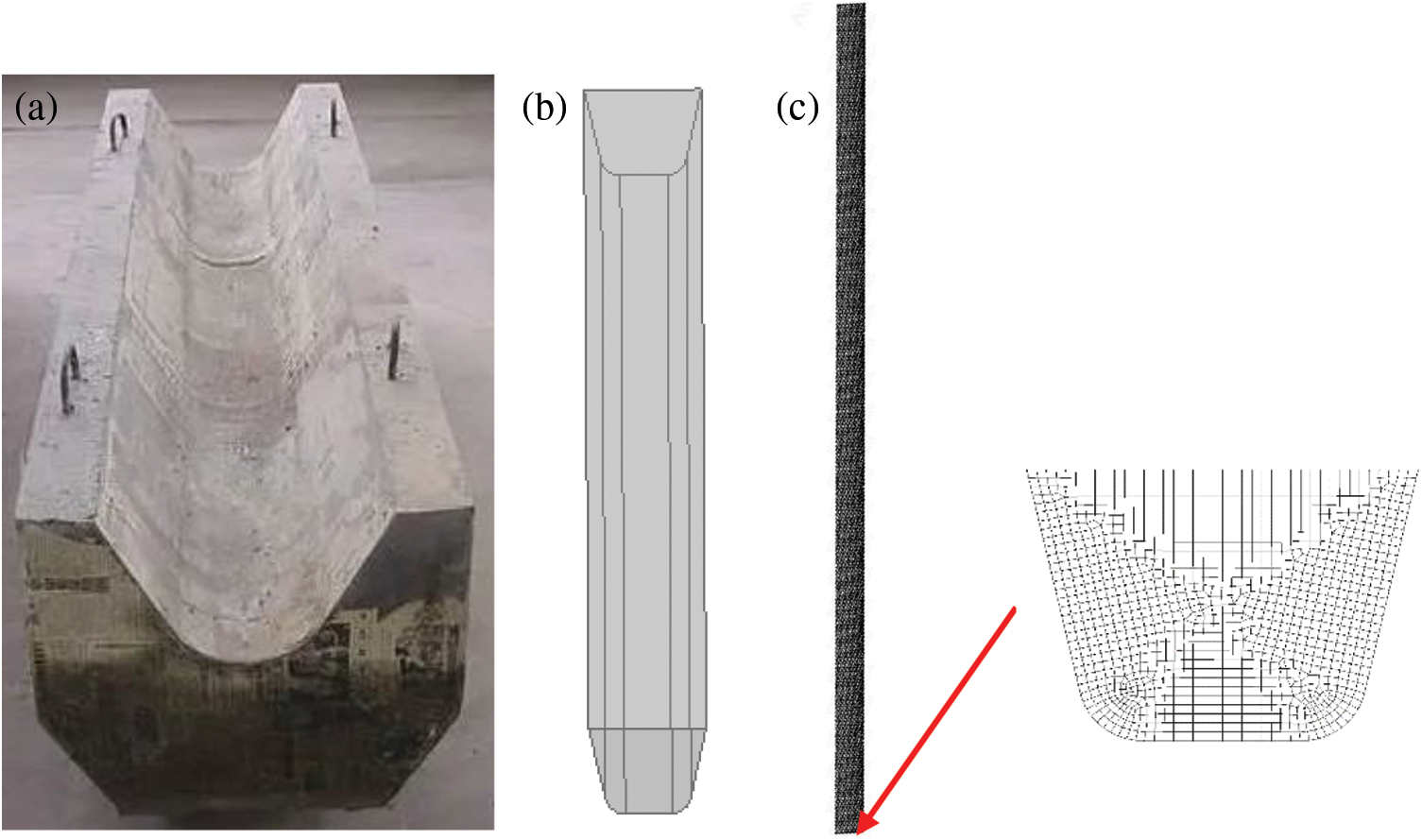
Figure 1: (a) Actual slag trench; (b) Physical modeling (c) Grid delineation
The density of high-temperature liquid slag is 2800 kg·m−3, and the specific heat capacity is 1302 J·kg−1 [27]. The viscosity of blast furnace slag is highly dependent on the temperature as well as on its material content [28,29], the viscosity of high-temperature slag is defined by the following equation, and the slag viscosity can be obtained using the Urbain model [30]. In the equation, A and B are parameters that depend entirely on the composition of the high-temperature slag. The empirical correlation between parameters A and B is shown in equations where A is in Pa·s·K−1, and B is in K.
where MO is the molar fraction of the network modifier, and Al2O3 is the total molar fraction of the slag particles sum.
The high-temperature slag flows inside the slag trench, and its flow law needs to be solved by the following equations [31], which need to be solved by combining the mass conservation equation, the momentum equation, the energy conservation equation, and the heat transfer equation. In the high-temperature slag flow, turbulence is fully developed and is described by the standard k-ε dual equation closed steady-state Reynolds time-averaged Navier-Stokes equations.
The conservation of mass equation is
where ρ is the density of the high-temperature slag, kg·m−3; u, v, w are the velocities of the high-temperature slag along the x, y, z directions, m·s–1, respectively.
The momentum equation is
where xj is the coordinate component in the i-direction, m; uj is the velocity component in the j-direction, m·s−1; p is the pressure, Pa; μ is the hydrodynamic viscosity, kg·m·s−1; μt is the turbulent viscosity, kg·m·s−1; g is the acceleration of gravity, m·s−2.
The turbulent viscosity [32] is calculated as shown in the following equation:
where μt is the turbulent viscosity.
The energy conservation equation is
where H is the enthalpy, J/kg; λ is the thermal conductivity, W·m−1·K−1; cp is the specific heat capacity of high-temperature slag, J·kg−1·K−1; σH is the enthalpy turbulence Prandtl number; q is the heat flow rate, W.
2.3 Grid-Independent Verification
Generally speaking, the finer the grid and the smaller the size, the more accurate the calculated results are, but at the same time, the speed of calculation decreases, and the amount of data obtained is larger. For this slag trench flow model structure, five types of meshes are adopted for calculation, 200,000, 290,000, 380,000, 620,000, and 900,000, respectively. The results obtained from the grid as a reference, respectively, compared the deviation of the calculation results obtained in different numbers of grids, and finally obtained the results shown in Table 1. We can see that the deviation of the velocity is only 0.52% when the number of grids increases from 380,000 to 900,000, so we think that the accuracy of the calculation at 380,000 grids can meet the requirements, and all the subsequent calculations in this paper use the grid division of 380,000 grids. In this paper, numerical simulations are carried out using commercial software fluent, and the governing equations as well as the boundary conditions, are described in the previous section.

As Fig. 2 gives the flow of high-temperature slag along the inside of the slag trench for different slopes when the inlet flow rate of high-temperature slag is 8 t/min and the inlet temperature is 1500°C.

Figure 2: Cloud map of velocity distribution in the slag trench
As can be seen from the velocity cloud diagram, the high-temperature liquid slag flows from the inlet, the slag is deposited at the bottom and flows along the slag trench, the initial inlet flow rate is small, and the velocity of both is approximately the same. As the high-temperature slag is influenced by gravity, it accelerates along the slag trench direction and reaches the maximum velocity in the middle of the slag trench. Due to the surface tension and the friction of the wall, the slag is always exchanging heat with the ambient air along the slag trench after it is poured out from the blast furnace, where the main heat exchange method is radiation heat exchange. The temperature of the high-temperature liquid slag gradually decreases, and its viscosity increases sharply as the temperature decreases. According to the previously mentioned equation for the viscosity of high-temperature slag as a function of temperature, it is known that the average velocity of the high-temperature slag decelerates slowly in the middle and later stages.
As shown in Fig. 3, the average velocity diagram shows that along the length of the slag trench, the overall trend of the high-temperature slag velocity is rising and then falling, and the overall average velocity is greater at a slope of 8% than at a slope of 6%. The maximum average velocity can reach 2.23 m/s at a slope of 8%, and after reaching the maximum average velocity, the flow rate of the high-temperature slag gradually slows down. At a slope of 6%, the maximum average velocity can reach 2.15 m/s, which is slightly lower than at a slope of 8%.

Figure 3: Variation of velocity along the length of the slurry trench for different slopes
Through the above analysis, we can know that after the high-temperature slag is discharged, the flow through the slag trench speed undergoes a process of first increasing and then decreasing, in which the temperature of the high-temperature slag changes, as shown in Fig. 4. As can be seen from the figure, the temperature of the high-temperature slag gradually decreases after the discharge, whether the slag trench with a slope of 8% or a slag trench with a slope of 6%. Inside the slag trench with a slope of 6%, the temperature of the high-temperature slag is higher than in the slag trench with a slope of 8%, where the temperature change is consistent with the change in the velocity field. In the slag trench with a slope of 8%, the flow rate of the high-temperature slag is faster, so the temperature of the high-temperature slag inside the slag trench with a slope of 8% is lower than that in the slag trench with a slope of 6% at the same position. The overall temperature drop trend is the same, and after discharge from the blast furnace interior and flow through the slag trench, the temperature of the high-temperature slag liquid is reduced by about 5 K and can be used rationally in the next step.
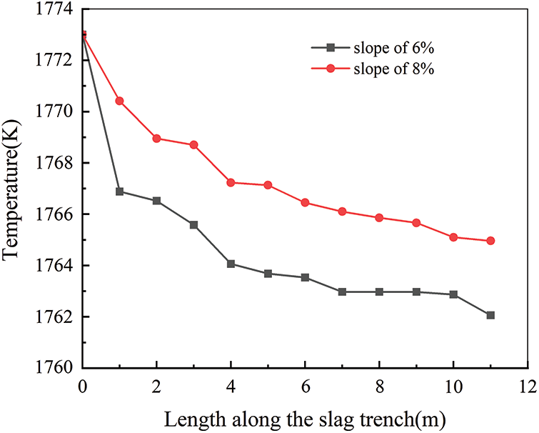
Figure 4: Temperature variation along the length of the slag trench at different slopes
The temperature clouds along the slag trench direction with different cross sections are shown in Fig. 5. As can be seen from the temperature cloud diagram, after the high-temperature slag flows out, it is heat exchanged with the environment, of which the main heat exchange method is radiation heat exchange due to the high temperature of the high-temperature slag. With the flow of high-temperature slag inside the slag trench, its temperature gradually decreases, the ambient temperature gradually increases, and the air is slowly heated. And the temperature change therein shows a warming process from the middle to both sides of the diffusion.
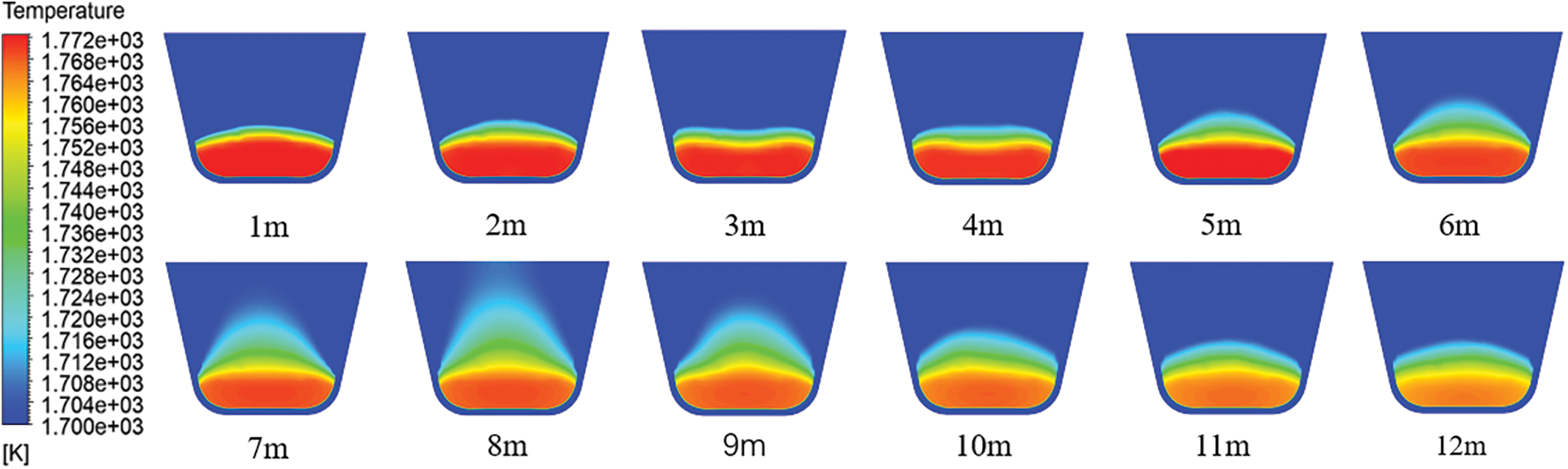
Figure 5: Temperature clouds of different cross-sections along the slag trench direction
Given a slurry trench slope of 6% and an inlet slag temperature of 1773 K, the inlet slag flow rate is varied to 4, 8, and 15 t/min to simulate different inlet flow rates for the real situation. By comparing the different inlet flow rates, the flow distribution of the high-temperature slag in the slag trench under different operating conditions is obtained.
Fig. 6 shows the velocity distribution along the slag trench for inlet flow rates of 4, 8, and 15 t/min, respectively. From the figure, it can be concluded that the velocity along the length of the slag trench at an inlet flow rate of 15 t/min is generally greater than that at a lower inlet flow rate, which follows the objective rule. When analyzing the three different inlet flow cases, all reach the peak velocity in the middle part, which is consistent with the previous analysis and will not be repeated here. In the inlet flow rate of 15 t/min, along the slag trench direction, the speed of high-temperature slag can reach up to 3.6 m/s. At this time, the flow rate of high-temperature slag is large, and there is a risk of danger, resulting in high-temperature slag pouring out of the results. For the two cases with flow rates of 4 and 8 t/min, the overall high-temperature slag flow rate is more gentle in the case of these two inlet flows.
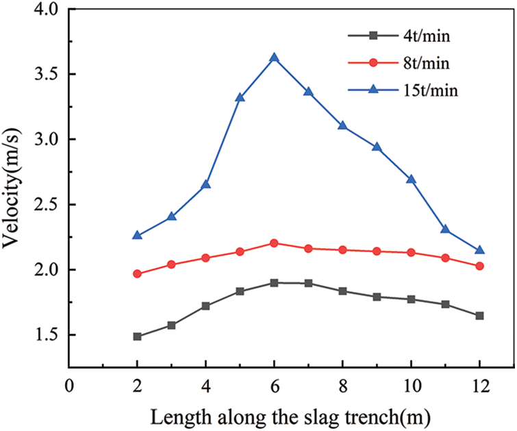
Figure 6: Velocity variation along the length of the slag trench for different inlet flows
Fig. 7 shows the temperature distribution along the slag trench direction with inlet flow rates of 4, 8, and 15 t/min, respectively. From the figure, we can learn that after the discharge of high-temperature slag, the temperature gradually decreases, and the higher the inlet flow rate, the higher the overall temperature of high-temperature slag liquid along the length of the slag trench than the temperature of the small inlet flow rate. This is due to the large inlet flow and high-temperature slag along the same slag trench flow. The shorter the flow through time, the same shorter the heat transfer time. The viscosity of high-temperature slag is related to its temperature. High-temperature slag is less viscous at higher temperatures, subject to less viscous force, and therefore flows faster.
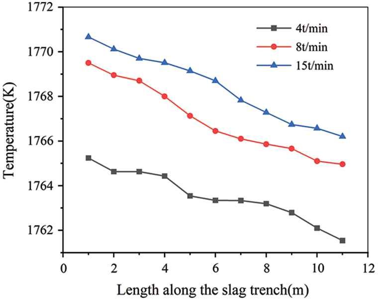
Figure 7: Temperature variation along the length of the slag trench for different inlet flows
3.3 Influence of Inlet Temperature
Given an inlet flow rate of 8 t/min and a slag trench slope of 6%, the temperatures of the incoming high-temperature slag are varied to 1673, 1773, and 1873 K, respectively, to simulate the real situation where the high-temperature slag flows into the slag trench at different temperatures and stays out through the slag trench. The velocity distribution of high-temperature slag inside the blast furnace slag trench under different working conditions is obtained by comparing the situation of high-temperature slag with different inlet temperatures.
Fig. 8 shows the velocity distribution of the high-temperature slag along the slag trench for inlet high-temperature slag temperatures of 1673, 1773, and 1873 K, respectively. From the previous section, it is clear that the viscosity of the high-temperature slag is highly temperature dependent and changes sharply with the temperature. Overall, the higher the temperature of the incoming high-temperature slag, the higher the average velocity, where the overall velocity of the high-temperature slag flowing inside the slag trench is maximum at 1873 K, and the maximum velocity can reach 2.75 m/s. From the point of view of reaching the maximum velocity, the higher the temperature, the closer the outlet reaches the maximum velocity, which is also due to the viscosity of the high-temperature slag related to the temperature, so it has been accelerated by gravity. Therefore the higher the initial temperature of the incoming high-temperature slag, the faster the flow will be and the more backward the location where the maximum velocity is reached.
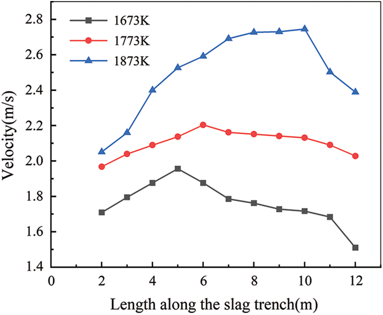
Figure 8: Velocity variation along the length of the slag trench for different inlet temperatures
In summary, this paper investigates the flow heat transfer process of high-temperature slag flowing through the slag trench and selects the inclination of the slag trench, high-temperature slag inlet flow rate, and inlet temperature as the three influencing factors. The above simulation results can show that the temperature and velocity of high-temperature slag during slag discharge are affected by the inclination, inlet flow rate, and inlet temperature. Our work can provide some data for the subsequent slag trench design, change the existing traditional slag trench, create a new type of intelligent slag trench to provide theoretical guidance, as well as for the rest of the method of utilization of high-temperature slag to provide a reference for the physical properties of the initial slag discharge.
In this paper, a three-dimensional model was established based on the process of high-temperature slag flowing through the slag trench, and the process of high-temperature slag flowing into the slag trench after slag discharge was simulated. The influence of the slag trench inclination, the inlet flow of high-temperature slag, and the inlet temperature of high-temperature slag are discussed, and the process of flow and heat transfer is analyzed to obtain the results of the flow field and temperature field of high-temperature slag flowing inside the slag trench, and the main conclusions are shown below:
(1) After the slag is discharged, it flows through the slag trench, where the velocity of the slag is related to the slope of the slag trench, and the higher the slope of the slag trench, the higher the velocity of the slag, where the highest average velocity can reach 2.23 m/s at a slope of 8%.
(2) In the case of different inlet flow rates, the greater the given inlet flow rate, the higher the velocity of the high-temperature slag flowing through the slag trench, and at the same position where the highest velocity is reached, the overall velocity trend is rising first and then decreasing, which indicates that the velocity trend of the high-temperature slag flowing through the slag trench is not related to the inlet flow rate, where the temperature change is related to the inlet flow rate, the greater the inlet flow rate, the slower the temperature change, the higher the temperature change at the outlet, the higher the temperature of the high-temperature slag liquid outlet.
(3) In the case of different inlet temperatures, the higher the given inlet temperature, the greater the overall flow rate of high-temperature slag through the slag trench. The higher the inlet temperature, the more backward the position where the maximum flow velocity is reached and the higher the maximum flow velocity.
Acknowledgement: Throughout the writing of this dissertation I have received a great deal of support and assistance. I would like to thank my tutors, Fuyong Su, for his valuable guidance throughout my studies. You provided me with the tools that I needed to choose the right direction and successfully complete my dissertation. I would particularly like to acknowledge my teammate, for their wonderful collaboration and patient support.
Funding Statement: The authors received no specific funding for this study.
Author Contributions: The authors confirm contribution to the paper as follows: study conception and design: Fuyong Su, Guangyan Fan; data collection: Cunwang Li, Bin Li; analysis and interpretation of results: Fuyong Su, Guangyan Fan; draft manuscript preparation: Guangyan Fan. All authors reviewed the results and approved the final version of the manuscript.
Availability of Data and Materials: All data for this study were obtained from on-site steel mill slag discharge conditions and slag trench design.
Conflicts of Interest: The authors declare that they have no conflicts of interest to report regarding the present study.
References
1. He, K., Wang, L. (2021). Development and current status of production energy consumption in ese iron and steel industry. China Metallurgy, 31(9), 26–35. [Google Scholar]
2. Kang, Y., Zhang, Y. Z., Jiang, M. F., Xing, H. W., Long, Y. et al. (2017). Progress and prospect of comprehensive utilization technology of blast furnace slag. 2017 National Academic Annual Conference on Blast Furnace Ironmaking, pp. 616–620. Kunming, Yunnan, China. [Google Scholar]
3. Fleischanderl, A., Fenzl, T., Neuhold, R. (2019). Dry slag granulation-the future way to granulate blast furnace slag. Iron & Steel Technology, 16(5), 80–85. [Google Scholar]
4. Wang, H. F., Zhang, C. X., Qi, Y. H., Dai, X. T., Yan, D. L. (2007). Current status and new development trend of blast furnace slag treatment technology. Iron and Steel, 2007(6), 83–87. [Google Scholar]
5. Liu, J. X. (2009). Experimental study on heat transfer characteristics of blast furnace slag waste heat recovery device (Master Thesis). Northeastern University, China. [Google Scholar]
6. Sun, Y. Q., Zhang, Z. T., Liu, L. L., Wang, X. D. (2015). Heat recovery from high temperature slags: A review of chemical methods. Energies, 8(3), 1917–1935. [Google Scholar]
7. Barati, M., Jahanshahi, S. (2020). Granulation and heat recovery from metallurgical slags. Journal of Sustainable Metallurgy, 6(2), 191–206. [Google Scholar]
8. Li, B., Li, J., Zhang, Z. Q. (2022). Blast furnace slag heat resource recovery and prospect of utilization. Science and Technology Wind, 4, 87–91. [Google Scholar]
9. Liu, M., Huang, Z. Y., Zhang, J. (2021). Research on status and trend of blast furnace slag treatment technology. Metallurgical Equipment, 266(2), 1–4. [Google Scholar]
10. Nexhip, C., Davidson, R., Norgate, T., Sanetsis, S., Washington, B. (2004). ‘Dry’ granulation of slags for producing cement binder. Green Processing 2004, Fremantle Western Australia. [Google Scholar]
11. Wang, Z. L. (2023). Advances in centrifugal granulation of high temperature liquid slag. Contemporary Chemical, 2023(4), 25–27. [Google Scholar]
12. Duan, W. J., Lv, X. J., Li, C. (2020). A review on the research progress of centrifugal granulation of blast furnace slag. Journal of Materials and Metallurgy, 19(2), 79–86. [Google Scholar]
13. Pickering, S. J., Hay, N., Roylance, T. F., Thomas, G. H. (1985). New process for dry granulation and heat recovery from molten blast-furnace slag. Ironmaking & Steelmaking, 12(1), 14–21. [Google Scholar]
14. Xie, D., Pan, Y., Flann, R., Washington, B., Sanetsis, S. et al. (2007). Heat recovery from slag through dry granulation. First CSRP Annual Conference, Melbourne. [Google Scholar]
15. Yoshida, H., Nara, Y., Nakatani, G., Anazi, T., Sato, H. (1984). The technology of slag heat recovery at NKK SEAISI. Conference of Energy Utilization in the Iron and Steel Industry, pp. 1–21. Singapore. [Google Scholar]
16. Anon (1986). Blast granulation system of BOF slag. ISIJ International, 26(9), 840–841. [Google Scholar]
17. Rodd, L., Koehler, T., Walker, C., Voermann, N. (2010). Economics of slag heat recovery from ferronickel slags. Sustainability for Profit Conference of Metallurgists (COM2010), pp. 3–17. Montreal, Quebec, Canada. [Google Scholar]
18. Qiu, L., Li, Y., Feng, Y. H. (2019). Numerical simulation of waste heat recovery from multi-size blast furnace slag in a moving bed. Journal of Engineering Ermophysics, 40(10), 2407–2414. [Google Scholar]
19. Gao, J., Feng, Y., Feng, D., Zhang, Z., Zhang, X. (2020). Solidification with crystallization behavior of molten blast furnace slag particle during the cooling process. International Journal of Heat and Mass Transfer, 146, 118888. [Google Scholar]
20. Xing, H. W., Wang, X. D., Long, Y. (2010). Numerical simulation of phase change heat transfer process in granulated steel slag. Iron and Steel Vanadium and Titanium, 31(1), 79–83. [Google Scholar]
21. Wang, H., Liu, C., Xing, H. W. (2022). High-temperature modification and air-quenching granulation of steel slag. Journal of Iron and Steel Research International, 29(5), 783–792. [Google Scholar]
22. Feng, Y. H., Gao, J., Feng, D. (2019). Modeling of the molten blast furnace slag particle deposition on the wall including phase change and heat transfer. Applied Energy, 248, 288–298. [Google Scholar]
23. Xiang, Y. H., Zhu, X., Wang, H. (2022). Numerical simulation of dynamic behavior and phase transition thermal characteristics of molten blast furnace slag droplets impacting the wall. Journal of Engineering Ermophysics, 43(5), 1337–1344. [Google Scholar]
24. Gu, W. F., Diao, J., Hu, R. X. (2022). Solidification and heat transfer of molten steel slag particles during air quenching process. Journal of Iron and Steel Research International, 30, 1834–1842. [Google Scholar]
25. Zhang, C., Wang, N., Chen, M. (2021). Hot slag modification with mechanical stirring: Motion and dispersion characteristic of modifier particle. ISIJ International, 61(11), 2754–2764. [Google Scholar]
26. Yang, C. Y. (2022). Numerical simulation study of heat transfer processes based on blast furnace slag particles wrapped around a shaped tube. Industrial Eating, 51(11), 43–46+50. [Google Scholar]
27. Wang, H., Ding, B., Liu, X. Y., Zhu, X., He, X. Y. et al. (2017). Solidification behaviors of a molten blast furnace slag droplet cooled by air. Applied Thermal Engineering, 127, 915–924. [Google Scholar]
28. Hou, J., Chen, B. X., Bai, C. G. (2023). Effect of Al2O3 on the properties and structure of blast furnace slag and its application. Iron and Steel, 58(5), 39–50. [Google Scholar]
29. Cao, Y. R., Xu, B., Wang, Z. Z. (2022). Molecular dynamics simulation of the effect of Al2O3 on the structure and viscosity of blast furnace slag in molten state. Sinter Pellets, 47(6), 57–65. [Google Scholar]
30. Urbain, G. (1987). Viscosity estimation of slags. Steel Research, 58, 111–116. [Google Scholar]
31. Fang, W. Y. (2020). Numerical simulation of high-temperature slag flow and phase transition heat on a rotating cup granulator (Master Thesis). Chongqing University, China. [Google Scholar]
32. Liu, T., Liu, J. D., Chen, Y. F. (2022). Applicability of different turbulence models in numerical simulation of intermediate ladle steel flow. Journal of Iron and Steel Research, 34(9), 973–980. [Google Scholar]
Cite This Article
 Copyright © 2023 The Author(s). Published by Tech Science Press.
This work is licensed under a Creative Commons Attribution 4.0 International License , which permits unrestricted use, distribution, and reproduction in any medium, provided the original work is properly cited.
 Downloads
 Citation Tools