
 Submit a Paper
 Propose a Special lssue
 Open Access
ARTICLE
Effect of the Wick Deflection Angles on Heat Transfer Characteristics for the Flat LHP
1
School of Energy and Power Engineering, University of Shanghai for Science and Technology, Shanghai, 200093, China
2
Aerospace System Engineering Shanghai, Shanghai, 201109, China
* Corresponding Author: Jiayin Xu. Email:
Frontiers in Heat and Mass Transfer 2023, 21, 107-123. https://doi.org/10.32604/fhmt.2023.041837
Received 08 May 2023; Accepted 12 July 2023; Issue published 30 November 2023
 View Full Text
 Download PDF
Abstract
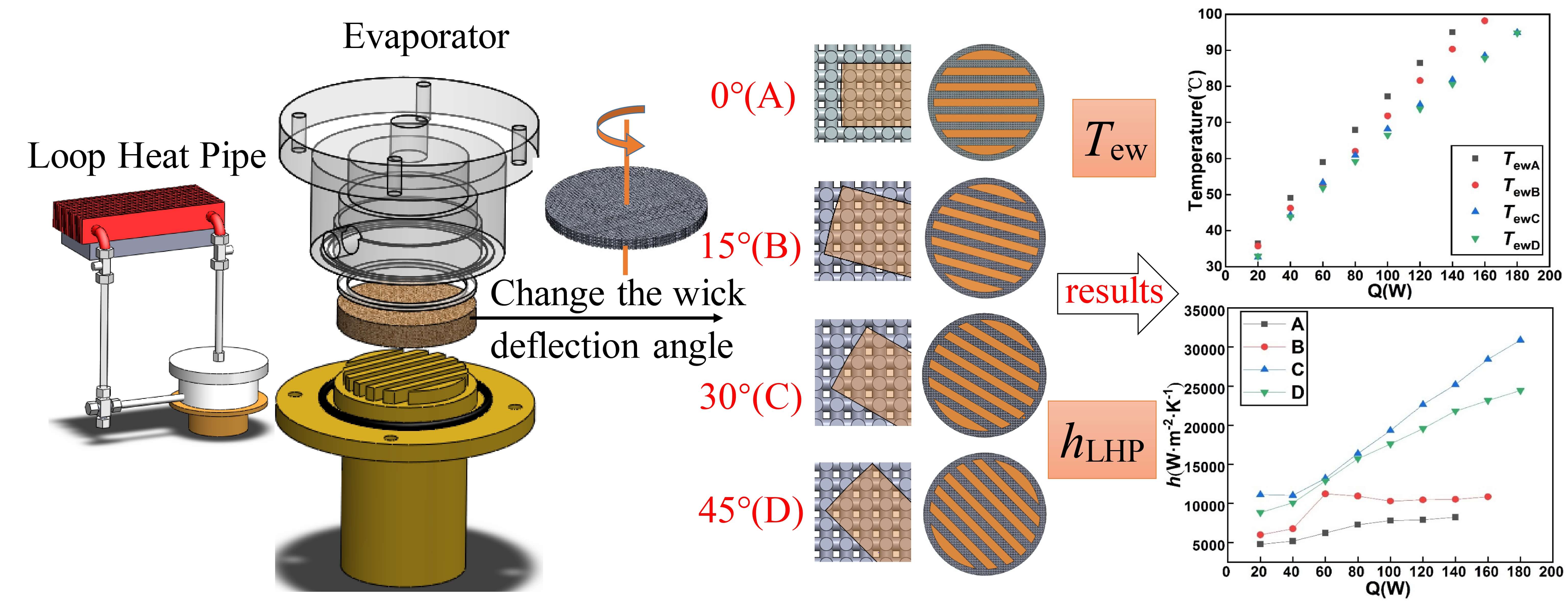
Loop Heat Pipe (LHP) is an efficient two-phase heat transfer device, which can be used in waste heat recovery, electronics cooling, aerospace and other fields. The wick, the core component of LHP, plays an important role in its start-up and operation. In this paper, the wick fabricated by 3D printing technology had uniform and interconnected pores. In the experiment, the position of the parallel vapor removal grooves was always fixed towards the vapor outlet. When the cylindrical wick was placed in the evaporator, the rotation angle relative to its central axis could be changed, thus changing the number and shape of the pores facing the vapor removal grooves. The wick deflection angle represented its change in spatial position relative to the fixed vapor removal grooves. The effect of the wick deflection angles on the heat transfer characteristics of the flat LHP was experimentally investigated. It was found that with the change of deflection angle, the number of pores in the evaporation-oriented zone would also change, which had a significant impact on the start-up process and heat transfer performance of LHP. When the deflection angle was 30°, LHP could start fastest at a low heat load of 20 W and operate stable at a high heat load of 180 W.Graphic Abstract
Keywords
Supplementary Material
Supplementary Material FileNomenclature
| AHeat | Effective heating area of the wick (m2) |
| d | Pore size of the wick (um) |
| h | Heat transfer coefficient (W/(m2·K)) |
| H | The thickness of the wick (mm) |
| k | Thermal conductivity (W/(m·K)) |
| K | Permeability (m2) |
| L | Length (m) |
| m | Mass of the wick (g) |
| ΔP | Pressure drop (Pa) |
| qm | Mass flow rate (g/s) |
| Q | Heat load (W) |
| r | The radius of the wick (mm) |
| RLHP | Thermal resistance of LHP (K/W) |
| t | Time (s) |
| T | Temperature (K) |
| v | Fluid velocity (m/s) |
| Va | Actual volume of the cylindrical pillars (mm3) |
| Vb | Bulk volume of a porous media (mm3) |
| Vv | Void volume of a porous media (mm3) |
| α | Empirical parameter determined by the porous media |
| ε | Porosity |
| μ | Dynamic viscosity (Pa·s) |
| π | Pi |
| ρ | Density (g/cm3) |
| Subscripts | |
| c | Condenser |
| ci | Condenser inlet |
| co | Condenser outlet |
| e | Effective |
| eo | Evaporator outlet |
| ew | Evaporator wall |
| s | Stainless steel |
| v | Vapor |
| w | Water |
Heat pipe is a cooling device that takes advantage of highly efficient phase change to dissipate heat from the heat source to the ambient [1]. Loop heat pipe (LHP), which features the separation of the vapor and liquid flows, is an improved version based on the traditional heat pipe. As the heat flux of the electronics increased, reliability and stable operation became crucial. Compared with the conventional heat pipe, LHP has many advantages, such as anti-gravity, long-distance heat transfer, and flexible arrangement [2]. Hence, it is a promising solution to thermal management in the fields of electronics cooling [3,4], battery [5–7], aerospace [8,9], solar heat utilization [10], waste heat recovery [11] and chemical reactors [12].
The wick is the core component of an evaporator because enough capillary pressure produced by the wick is required to maintain the working fluid circulation in the LHP [13]. Besides that, the material property and the structure of wick play a vital role in working fluid transportation in the wick. The heat transfer performance of the LHP is also dependent on these two factors. According to the literature [14], it was suggested that the wicks with low effective thermal conductivity (etc.), high permeability, high porosity and relatively small pore radius were favorable for the LHP operation. Lots of materials were selected to manufacture wicks. Although most of the LHPs equipped with the copper wick showed good heat transfer performance in operation, heat leakage was also severe due to the high thermal conductivity of copper. Thus, metal materials with relatively low thermal conductivities, such as nickel [15], titanium [16], stainless steel [17] and nonmetal materials like carbon fiber [18], ceramic [19], polytetrafluoroethylene (PTFE) [20] with extremely low thermal conductivities were used to prepare the wick. Despite that, high evaporation efficiency resulting from the copper wick was also taken into consideration. Thus, many attempts were made to address the heat leakage from the copper wick. The effect of wick oxidation on the thermal performance of copper-acetone loop heat pipes was investigated by Kumar et al. [21]. Compared with the copper wick, the copper oxidation wick reduced heat leakage due to its low thermal conductivity, and the thermal performance of the LHP was significantly improved. The heat leak of the copper wick and the copper-oxide wick was found 18% and 7% of input heat loads, respectively. When the evaporator temperature was controlled below 100°C, the LHP with 50% charging ratio could transfer a heat load of 90 W (hEvp = 900 W/(m2·K)) and 180 W (hEvp = 2500 W/(m2·K)) for the copper wick and the oxidation wick, respectively.
Another solution is to optimize the manufacturing method of the wicks. Sintered powder is the most commonly used method. Sintered powder wick has wider pore size distribution, and small pore radii (1.0 um) can be realized. Thus, it has the advantage of high capillary force. However, its aperture distribution is random, and closed pores are common. High randomness leads to heterogeneity of the thermal behavior of fluid in the wick [22]. Although two sintered wicks were made with identical parameters, heat transfer performance was not the same. Additionally, the small porosity and relatively low permeability of sintered wicks may lead to dry-out in LHP at high heat fluxes. In response, some researchers tried to add pore former in the sintered powder to obtain the wick with high porosity and permeability. Kumar et al. [23] used naphthalene as the pore former and found that the wick porosity and permeability increased with the increase of pore former content. Besides, another commonly used wick is screen mesh wick, which is a certain number of layers of mesh fixed in the evaporator through solid sintering or spot-welding technology. It has the advantages of a simple structure, low price and convenient processing. Also, it has uniform pores and regular pore shape. But a low capillary force was caused by its large pore size, and a high thermal resistance between layers was unneglectable.
The drawbacks of the two wicks mentioned above were that the pore size and shape of the passage in the wick cannot be controlled. The emergence of 3D printing technology makes it possible to control the wick structure. Richard et al. [24] fabricated the wick for LHP evaporator via direct metal laser sintering (DMLS) technology. The developed LHP with the 3D-printed wick could reach a maximum heat load of 125 W. In recent years, a 3D selective laser melting (SLM) technology has been used to fabricate the wick, and relevant research was conducted [25,26]. The pores of the wick made by 3D printing technology were interconnected, which avoided the high randomness and closed pores in the traditional sintered wick. High porosity, appropriate pore radius, low effective thermal conductivity and high permeability of the wick were also realized [27].
In this paper, the stainless-steel wick was fabricated by metal 3D printing technology. Owing to the elimination of high randomness in the 3D-printed wick, the pores of the wick are uniform and interconnected. Thus, the results of the same wick in the LHP experiments should be more stable. To be more specific, the temperature profiles of the LHP during the start-up and the operation were supposed to be similar. Unfortunately, obviously different temperature profiles were observed. As the assemble of the wick into the evaporator was casual, the deflection angle of the wick on the vapor removal grooves may be another potential factor affecting the performance of LHP. So far, it has not been proposed and studied yet. Hence, the effect of the deflection angles of the 3D-printed wick on the heat transfer characteristics of LHP was investigated and analyzed in this paper. This may help to optimize the design of the wick and evaporator of the LHP. Subsequently, the performance of the LHP is supposed to be better and more stable.
2 LHP Experimental System and Metal 3D-Printed Wick
2.1 Experimental System Design
The schematic of the LHP with a flat evaporator adopted in this paper are shown in Fig. 1, which was mainly composed of an evaporator, a condenser and two transport lines for vapor and liquid working fluid. The evaporator consisted of a plastic shell, a 3D-printed wick and a brass baseplate. The 3D-printed wick was sandwiched between the plastic shell and the brass baseplate. Thus, the spaces in the evaporator were divided into two parts, namely the space above the wick was the compensation chamber, supplying working fluid to the wick. The other space below the wick served as the evaporation area. There were six parallel vapor removal grooves with a cross-section of 2 mm × 3 mm milled on the upper side (the diameter is 27 mm) of the brass baseplate, and the lower side was a heating block with three heating rods (CIR-10153/240 V CARTRIDGE HEATER-250 W) inserted as heat source. The condenser was composed of around 370 mm copper tube with outer diameter of 6 mm and wall thickness of 1 mm and 36 copper-plated aluminum fins (85 mm in length, 15 mm in width and 0.5 mm in thickness), and an axial fan was mounted on the condenser. All joints of the LHP were sealed to avoid air leakage. The working fluid used in the experiment was deionized water.
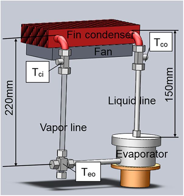
Figure 1: Flat loop heat pipe
Additionally, T-type thermocouples were used to measure the temperatures of the LHP. The temperature measurement points were shown in Fig. 1. There were 4 temperature measurement points on the bottom side of the brass baseplate in Fig. 2. They were averaged and considered as the evaporator wall temperature (Tew). The other temperatures included the evaporator outlet temperature (Teo), the condenser inlet temperature (Tci) and the condenser outlet temperature (Tco). All T-type thermocouples used in the experiment were the sheathed thermocouples. In order to improve the measurement accuracy, three thermocouples (measuring Teo, Tci and Tco) were inserted into the LHP, contacting the flow directly.
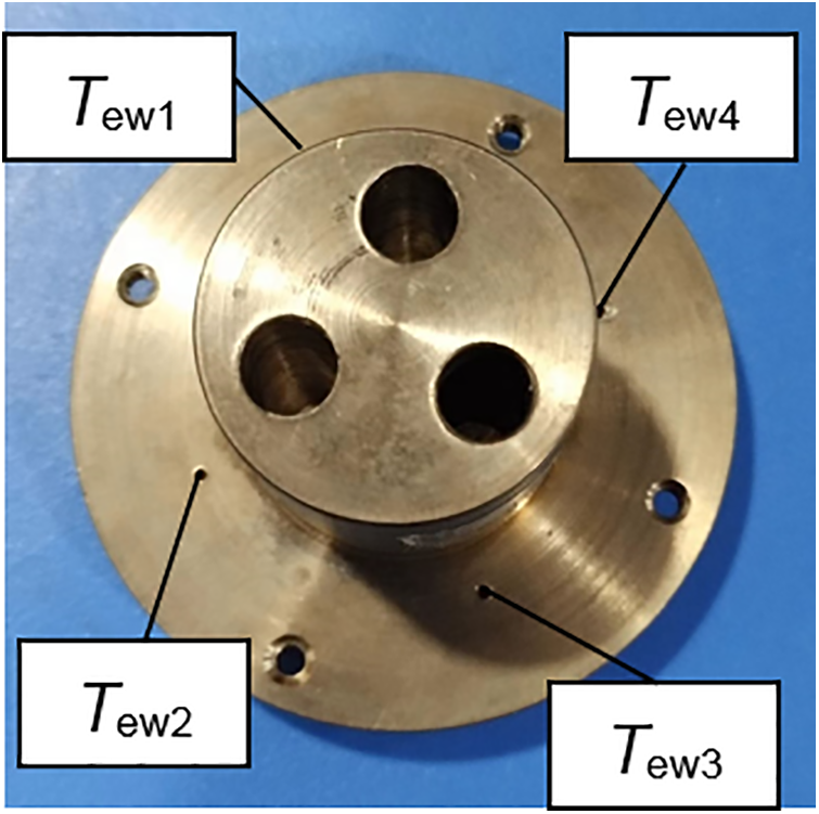
Figure 2: Brass baseplate
2.2 Fabrication of Metal 3D-Printed Wick
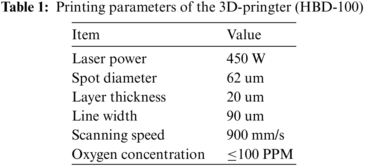
The advantages of selective laser melting (SLM) technology for the wick preparation are geometric freedom, controllable porous parameters and mass customization [28]. An HBD-100 metal 3D printer based on SLM technology was used to prepare the wick which was made of 316 L stainless steel. The printing parameters were listed in Table 1.
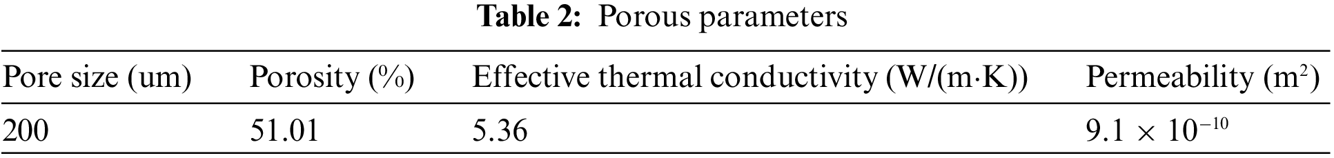
As presented in Fig. 3a, the basic element of the wick was a cubic structure created by 12 cylindrical pillars in the respective X, Y and Z axis of the 3D Cartesian coordinate system. The diameter of cylindrical pillar was 400 um, and the pore size (d) in the cubic structure was determined by the distance between two parallel adjacent pillars (200 um). The 3D-printed wick in this paper was designed as the combination of these cubic structures. The wick was 29.78 mm in diameter, and 5.46 mm in thickness. It was manufactured by the 3D printer layer by layer with a laser beam scanning on stainless steel powder. After that, a 3D-printed wick with order porous structure was shown in Fig. 3b. Porous parameters, including pore size, porosity, effective thermal conductivity and permeability, were listed in Table 2.
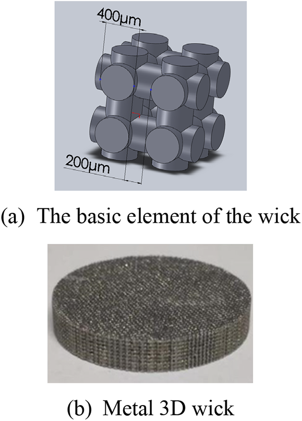
Figure 3: Design of the 3D-printed wick
The porosity of the wick is defined as the ratio of volume of all the void space Vv to the bulk volume Vb of a porous media:
where Va is the actual volume of the cylindrical pillars (stainless steel); m is the mass of the wick(14.867 g); r is the radius of the wick (14.89 mm); H is the thickness of the wick (5.46 mm); ρ is the density of stainless steel (7.98 g/cm3).
The effective thermal conductivity ke was calculated with the correlation by Alexander [29] as following:
where kw is the thermal conductivity of water (working fluid) and ks is the thermal conductivity of stainless steel (wick material); α is an empirical parameter determined by the porous media, which is a constant equal to 0.59; ε is the wick porosity.
Permeability K reflects the ability of working fluid transportation in the wick. The theoretical permeability was calculated by Eq. (S1) based on pore size and porosity [30]. For water flow in the wick, inertial effects are negligible under sufficiently small velocity. In the case, the permeability of the wick is determined by Darcy’s law [31], that is the pressure drop (ΔP) across the porous medium per unit length (L) is inversely proportional to the permeability (K) and proportional to the effective fluid velocity (v), the dynamic viscosity (µ):
thus, permeability (K) can be calculated by measuring the pressure drop (ΔP) and fluid velocity (v).
Accordingly, measuring set-up consists of an injector, an injection pump, a sample holder with a wick, a pressure transmitter, a beaker and several hoses for connection. The pressure transmitter was used to measure the pressure drop across (ΔP) the wick. An injection pump with flow settings ranging from 0.001 to 43.349 ml/min and an injector with a capacity of 60 ml were used to set the volume flow rate through the wick. The water crossing area of the wick was obtained according to the model. Then, the effective fluid velocity (v) could be calculated. Besides, L was equal to the thickness of the wick and µ was the dynamic viscosity of water at 20°C.
The permeability of the wick was experimentally evaluated and summarized in Fig. 4. The permeability (K) reaches a relatively constant value of K = 9.1 × 10⁻¹⁰ m2 at a maximum flow velocity of approximately 0.004 m/s (2.5 g/s).
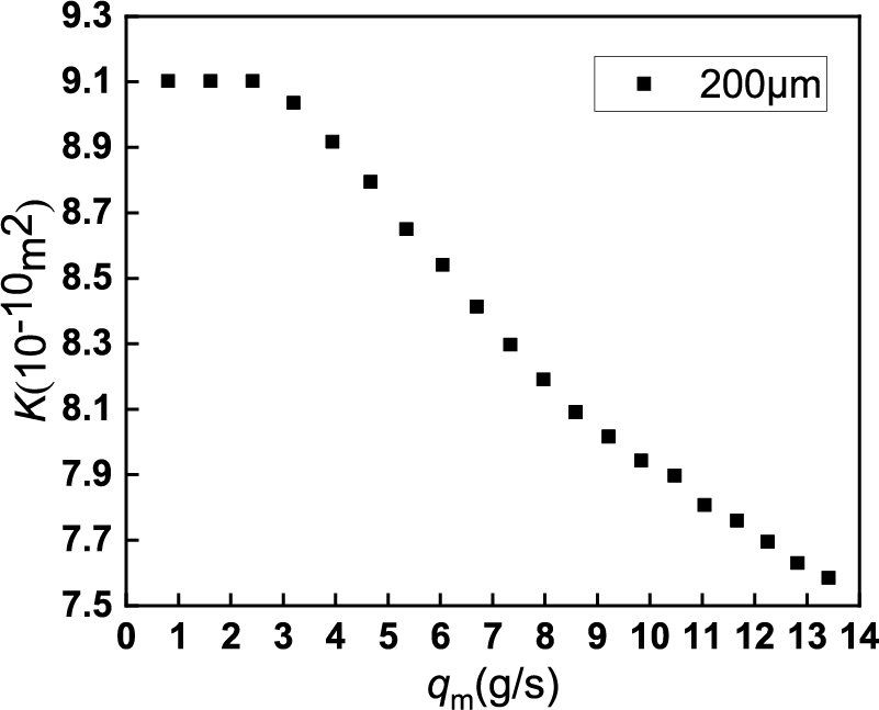
Figure 4: Permeability (K) test results for different mass flow rates (qm)
2.3 Definition of the Deflection Angle between Wick and Vapor Removal Groove
As shown in Fig. 5, there were 6 grooves milled on the brass plate, serving as the vapor removal groove. While 7 fins on the brass plate could conducted heat from heat source to the bottom of the wick. It should be noted that it was necessary to figure out the vapor generation in the zone of the wick in contact with the fins, because almost all vapor generated in this zone (near the heat source). The way of contact played a vital role on the vapor generation and consequent thermal performance. To be more specific, the deflection angle of the wick on the vapor removal groove is a non-negligible factor. In Fig. 5, the centerline of fins was designated as the X-axis. Similarly, another X-axis could also be defined on the surface of a 3D-printed wick in Fig. 6. Thus, the deflection angle in this paper was defined as the angle of these two cross X-axis.
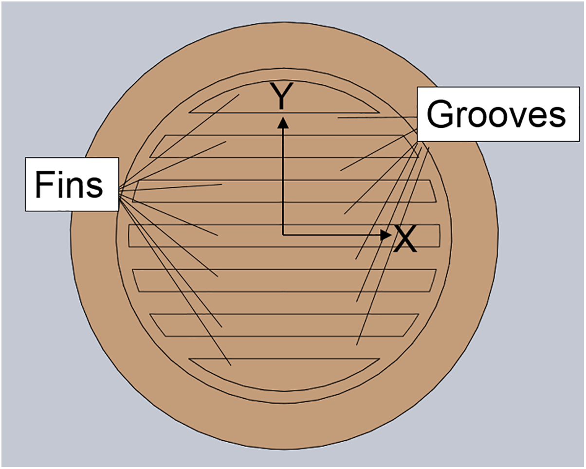
Figure 5: Planform of heating baseplate groove
Figure 6: Local enlarged planform of the wick
The combinations of the deflection angle and partial enlarged details were shown in Fig. 7. Due to symmetry, only four deflection angles were selected in this paper, namely 0° (A), 15° (B), 30° (C) and 45° (D). According to the partial enlarged drawings, the changing deflection angles led to the variation of the actual effective heating area and the number of uncovered pores in the wick. Besides, some pores of the wick were partially occluded by the fins. In this case, the partially exposed pores of A in Fig. 7a were mostly rectangular, while in other deflection angles were triangular, trapezoidal or pentagonal. Table 3 listed the approximate number of pores covered by the fins. The decreasing order of covered pores number was A, B, D, C. Besides, the number of completely covered and mostly covered pores combined of all the combinations were close. Thus, it could be concluded that the decreasing order of the actual effective heating area and the corresponding number of uncovered pores of the four deflection angles was C, D, B, A.
Figure 7: Combination diagram of wick and vapor removal groove
It should be noted that the results obtained in Table 3 were theoretical model estimates. In practice, the printed wick inevitably deviated from the model. In addition, the wick mounting angles might also be slightly skewed.
2.4 Auxiliary Equipment and Experimental Procedure
The auxiliary equipment included a climate chamber, a working fluid charging system (a vacuum pump and a graduated cylinder), a data acquisition unit and a DC power supply. The whole experiment was carried out in the climate chamber, which ensured that the ambient temperature was maintained at 20 ± 1°C. The vacuum condition in the evaporator was achieved for the LHP operation through a two stage rotary vane vacuum pump (RVD-1) with a pumping rate of 1 L/s working for an hour. A graduated cylinder was applied to ensure the amount of working fluid charged into the LHP. The data acquisition unit, Agilent 34972 A, was used to connect the thermocouple to record the temperature with the frequency of 0.5 Hz during the experiments. Heat load was supplied by the EA-PSI 9200-25 programmable DC power with the accuracy of 0.2% and 0.012% for the electric current and voltage (measured by Agilent U3402 A), respectively. Thus, according to the method proposed by Kline et al. [32], the uncertainty range of heat loads was from 2.73% (20 W) to 0.92% (180 W).
Before the experiments, the 3D-printed wick was placed into the evaporator according to the deflection angle relative to the vapor removal groove, and the vacuum pump was used to vacuum the system to achieve the required vacuum degree. Then the deionized water with non-condensable gas removed was filled into the evaporator of LHP. The total volume of the LHP was 18.6 ml, and a volume of 9.3 ml deionized water was charged into the LHP with the charging ratio of 50%. Subsequently, the climate chamber was activated to adjust the temperature. It was time to conduct the experiments until all temperature readings were uniform.
During the experiments, the condenser was always located above the evaporator. The LHP start-up was conducted at a heat load of 20 W. After the LHP started successfully, the LHP operation was carried out. The initial heat load started from 40 W, and then increased by 20 W each time until the maximum heat load was reached.
2.5 Data Processing and Uncertainty Analysis
When the vapor generated in the evaporator and flowed to the condenser inlet, Tci rose significantly. The interval from the beginning to the increase of Tci was considered as the evaporation activation time. When the vapor condensed in the condenser and flowed to the condenser outlet, Tco rose obviously. That is the working fluid circulation was completed. Thus, the interval from the beginning to the increase of Tco was considered as the startup time for the LHP.
The thermal resistance and heat transfer coefficient of the LHP were used as the indexes to measure the heat transfer performance. A low thermal resistance and a high heat transfer coefficient were desired.
The thermal resistance of LHP is defined as:
where Tew is the evaporator wall temperature (°C); Tc is the average temperature of condenser (°C); Tci is the condenser inlet temperature (°C); Tco is the condenser outlet temperature (°C); Q is the evaporator heat load (W).
The heat transfer coefficient of LHP is:
where Q is the heat load of the evaporator (W); AHeat is the effective heating area of wick (m2); Tew is the evaporator wall temperature (°C); Tv is the vapor temperature (°C). Since the thermocouple is contact with vapor directly, the evaporator outlet temperature Teo (°C) can be used as the vapor temperature.
Temperature uncertainty of thermocouple was ± 0.3 K, the maximum uncertainty of thermal load was 2.73% at a heat load of 20 W. The maximum uncertainties of RLHP and h were 3.98% and 9.29% at a heat load of 20 W.
3 Effect of Deflection Angles on the LHP Performance
The start-up stage can assess the reliability and stability of the LHP. Literature [33] summarized four characteristics to evaluated the startup performance: (1) startup times, (2) startup temperature, (3) minimum startup power, (4) temperature fluctuation. Longer startup time leads to higher evaporator wall temperature, which may cause damage to electronic components in practical applications. Thus, LHPs are expected to start up faster [34].
The start-up processes of four LHPs with different wick deflection angles were shown in Fig. 8. The startup parameters of these four LHPs were listed in Table 4. A sharp rise in the condenser inlet temperature Tci indicated that vapor was generated and reached the condenser inlet. The LHP start-up time could be recognized as an obvious increase of the condenser outlet temperature Tco. In Table 4, it was found that the evaporation activation time of four groups were of difference. The evaporation activation time readings for A and B were both 94 s, while for C and D were 62 and 66 s, respectively. Although the 3D-printed wick and the heat load were the same, the start-up parameters were different. That was caused by the different contact conditions owing to four deflection angles. After evaporation activation, some time was necessary to reach the enough pressure for pushing the working fluid from the evaporation zone to the compensation chamber through the condenser. In another word, the circulation of working fluid in the LHP was established. The LHPs with A and B could start successfully in 224 and 242 s, respectively. While it was 96 s for the LHP with D, and only 80 s was taken for the LHP with C.
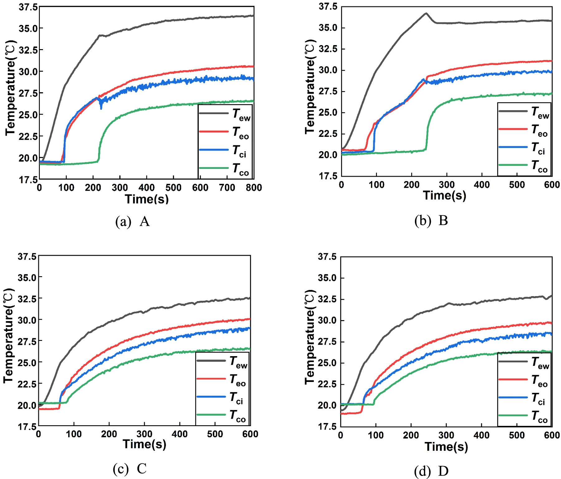
Figure 8: Loop heat pipe starting performance diagram
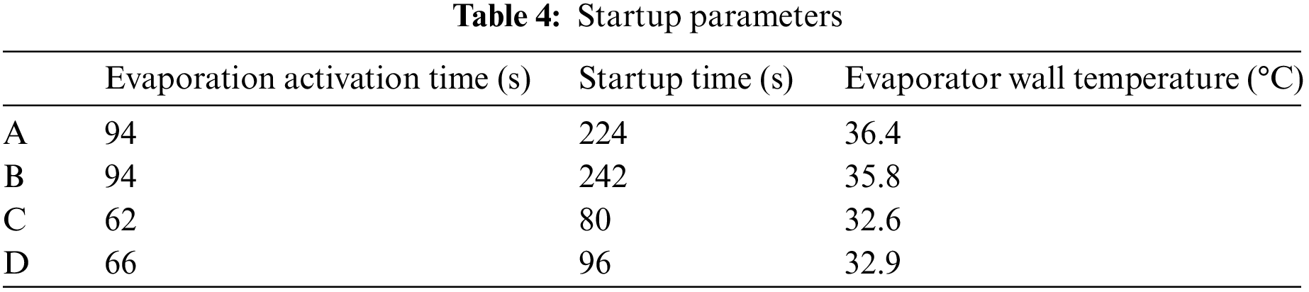
As mentioned in Section 2.3, it was obvious that the contact conditions for the LHPs with C and D were superior to those with A and B. On the one hand, the number of covered pores in the wicks of A and B were more than those of C and D. That was a larger contact area between the wick and the fins (i.e., the actual effective heating area), resulting in a high vapor generation rate. On the other hand, the numbers of uncovered pores in the wicks of C and D were more than those of A and B, which contributed to the greater vapor mass flow rate in C and D. Consequently, it took less time to achieve the evaporation activation and the circulation of working fluid in the LHP.
As shown in Fig. 8, the steady state without temperature oscillation was observed in all four LHPs. However, a peak wall temperature of the LHP with B was found from the transient state to the steady state. Due to a low vapor mass flow rate in the LHP with B, the working fluid circulation was delayed. Hence, heat accumulated in the evaporator, leading to an increasing evaporator wall temperature. After vapor was condensed into liquid, it became subcooling water and flowed back to the evaporator. As a result, the superheat of the evaporator was cooled, and the evaporator wall temperature decreased, resulting in a peak evaporator wall temperature. The temperature profile of the LHP with A was similar to that with B, but it could start faster than the LHP with B. Therefore, no evident overshoot in the evaporator wall temperature was shown. Additionally, the starting performance diagram showed that the LHP with A took more time to reach the steady state than the LHP with the others.
Compared with the LHPs with A and B in Table 4, the LHPs with C and D could not only start fast in 100 s, but also maintain the evaporator wall temperature below 33°C. In a word, the start-up performance of the LHPs with C and D were much better than that with A and B.
After the successful start-up, the heat transfer performance could be analyzed according to the LHP thermal resistance (RLHP) and the heat transfer coefficient (h). The maximum heat load of the LHP was determined by the allowable evaporator wall temperature (Tew) below 100°C. Figs. 9 and 10 showed the evaporator temperature varying from different heat loads, the LHP thermal resistances (RLHP) and the heat transfer coefficients (h) of all four LHPs. According to the allowable evaporator wall temperature, the maximum heat loads of the LHPs with A and B were 140 and 160 W, respectively. While the LHPs with C and D could reach 180 W. It was indicated that the LHPs with C and D had optimal cooling performance, and relatively poor performance was for the LHP with A.
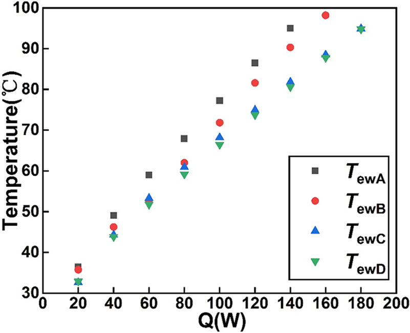
Figure 9: Evaporator wall temperature at different heat loads
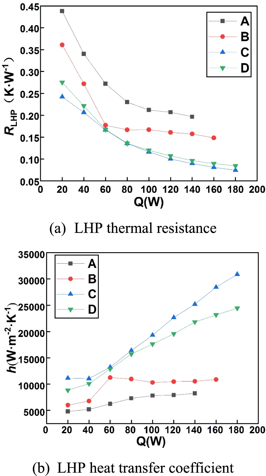
Figure 10: Comparison of operation characteristics of loop heat pipes
For the LHP with A, it could be seen from Fig. 9 that the evaporator wall temperature (Tew) was higher than others during the start-up. Moreover, as the heat load increased, the evaporator wall temperatures (Tew) in the LHP with A was always higher than that in other groups. At a heat load of 140 W, the evaporator wall temperature reached 95°C. Accordingly, in Fig. 10, the LHP thermal resistance of the LHP with A was far higher than others’ at the same heat load, and the heat transfer coefficients were always the lowest among four LHPs. It was caused by the lowest vapor mass flow rate and vapor generation rate in the evaporator of the LHP with A. Hence, the thermal performance of the LHP with A was limited because of the low vapor mass flow rate.
For the LHP with B, although the evaporator wall temperature (Tew) was close to those of the LHPs with C and D at the heat loads below 80 W, it was gradually higher than those of the LHPs with C and D with the increase of heat load in Fig. 9. At the high heat loads (above 60 W), Tew of the LHP with B began to close to the LHP with A, and Tew was reached 98.2°C at a heat load of 160 W. When the heat load reached 60 W, back flow of vapor happened in the LHP with B. As shown in Fig. 11, vapor generated in the wick and entered into the compensation chamber through the pores. That was caused by the relatively large pore diameter (200 um) and covered pores. Due to the back flow of vapor, the temperature of the water in compensation chamber increased and temperature difference between evaporating surface of the wick and compensation chamber decreased. Accordingly, the pressure difference reduced and the circulation driving force weakened. As a result, the less mass flow of vapor and reflux liquid ran out of the condenser in the circulation was present. Thus, the evaporator wall temperature was close to that of LHP with A at high heat loads. Correspondingly, the decrease of the LHP thermal resistance was not obvious at the heat loads above 60 W and the LHP heat transfer coefficient was even slightly lower in Fig. 10.
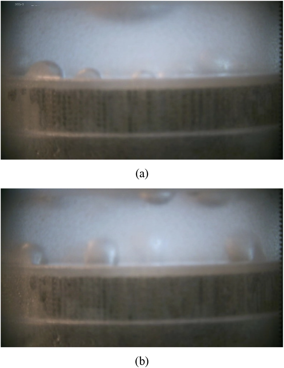
Figure 11: Back flow of vapor in the evaporator of the LHP with B
For the LHPs with C and D, their Tews were always lower. Since the number of uncovered pores and the actual effective heating area in the LHP with C were the largest, a high vapor generation rate and a consequent high flow rate in the wick were realized. Therefore, the heat transfer coefficient of C was the highest, and the corresponding thermal resistance was the lowest among four LHPs. The vapor mass flow rate of the LHP with D was secondary only to that of C. By contrast, the heat transfer performance of the LHP with C was better.
It was showed that the deflection angle of the 3D-printed wick on the vapor removal grooves seemed to significantly affect the heat transfer performance of the LHP. Among the four LHPs, the LHP with C of 30° had relatively better wall temperature control ability, lowest thermal resistance and highest heat transfer coefficient during operation. When the heat load increased to 180 W, the wall temperature of evaporator was 94.9°C, the thermal resistance of LHP was 0.074 K/W, and the heat transfer coefficient was 30,883 W/(m2·K).
In this paper, the effect of the 3D-printed wick’s deflection angle on thermal performance was investigated. It was found that the deflection angle of the wick had a significant influence on the start-up process and the operation of the LHP:
• During the start-up process at a heat load of 20 W, the temperature profiles of all four LHPs were different. The LHPs with C and D could activate evaporation in 62 and 66 s and complete working fluid circulation in 80 and 96 s with the evaporator wall temperature of about 32°C, respectively. The number of uncovered pores and the effective heating area owing to different contact conditions between the 3D-printed wick and the vapor removal grooves were the main reason to affect the start-up performance.
• The different deflection angles had a significant impact on the evaporator wall temperature of the LHPs. The maximum heat loads of the LHPs were 140 W for A, 160 W for B, and180 W for C and D, with the allowable Tew below 100°C. The least uncovered pores of the LHP with A and the backflow of vapor in the LHP with B caused poor thermal performance. In the operation process, the thermal resistances of the four combinations of LHP with different angles differed distinctly, which were always smaller at 30°and 45° and larger at 0° and 15°. The heat transfer coefficients of the four combinations of LHP with different angles varied greatly with the increase of heat load. It was always the maximum at 30° and minimum at 0°, and the gap became larger with the increase of heat load.
• When the deflection angle was 30°, the LHP with C showed superior thermal performance. It could activate the evaporation and complete the working fluid circulation in 80 s, and the maximum heat load of 180 W was achieved with a low LHP thermal resistance of 0.074 K/W and a high heat transfer coefficient of 30,883 W/(m2·K).
However, there are also some limitations. These conclusions only apply to the wick with a diameter of 200 um. The study of the angle effect is also only applicable to the wick and vapor removal grooves with regular structures.
Whereas, the study may give a reference for the optimization of the design of the wick and evaporator to improve the LHP performance. Additionally, this may help inspire people to think about further increasing the heat transfer capacity of LHPs and other heat exchangers by simple methods such as changing the installation mode and achieving a more stable working state.
Acknowledgement: We would like to thank Shanghai Hanbang Lianhang Laser Technology Co., Ltd. for helpful advice.
Funding Statement: The authors received no specific funding for this study.
Author Contributions: The authors confirm their contribution to the paper as follows: study conception and design: Z.H. Hu, S.X. Sun; data collection: C.Y. Yuan; analysis and interpretation of results: Z.H. Hu, S.X. Sun, J.Y. Xu; draft manuscript preparation: S.X. Sun, J.Y. Xu; manuscript supervision: Z.H. Hu, Y. Cao. All authors reviewed the results and approved the final version of the manuscript.
Availability of Data and Materials: The authors confirm that the data supporting the findings of this study are available within the article and its supplementary materials.
Conflicts of Interest: The authors declare that they have no conflicts of interest to report regarding the present study.
Supplementary Materials: Table S1 (the data that supporting the findings of this study) and Eq. (S1) (the formula of theoretical permeability) are available online at https://doi.org/10.32604/fhmt.2023.041837.
References
1. Chen, X. P., Ye, H. Y., Fan, X. J., Ren, T. L., Zhang, G. Q. (2016). A review of small heat pipes for electronics. Applied Thermal Engineering, 96, 1–17. [Google Scholar]
2. Maydanik, Y. F. (2005). Loop heat pipes. Applied Thermal Engineering, 25(5–6), 635–657. [Google Scholar]
3. Tian, W., He, S., Liu, Z. C., Liu, W. (2019). Experimental investigation of a miniature loop heat pipe with eccentric evaporator for cooling electronics. Applied Thermal Engineering, 159, 113982. [Google Scholar]
4. Wang, X. L., Yang, J. X., Wen, Q. W., Shittu, S., Liu, G. M. et al. (2022). Visualization study of a flat confined loop heat pipe for electronic devices cooling. Applied Energy, 322, 119451. [Google Scholar]
5. Bernagozzi, M., Miche, N., Georgoulas, A., Rouaud, C., Marengo, M. (2021). Performance of an environmentally friendly alternative fluid in a loop heat pipe-based battery thermal management system. Energies, 14(22), 7738. [Google Scholar]
6. Bernagozzi, M., Georgoulas, A., Miche, N., Rouaud, C., Marengo, M. (2021). Novel battery thermal management system for electric vehicles with a loop heat pipe and graphite sheet inserts. Applied Thermal Engineering, 194, 117061. [Google Scholar]
7. Singh, R., Lapp, G., Velardo, J., Long, P. T., Mochizuki, M. et al. (2021). Battery cooling options in electric vehicles with heat pipes. Frontiers in Heat and Mass Transfer, 16(1), 1–8. [Google Scholar]
8. Hodot, R., Sartre, V., Lefevre, F., Sarno, C. (2016). Modeling and experimental tests of a loop heat pipe for aerospace applications. Journal of Thermophysics and Heat Transfer, 30(1), 182–191. [Google Scholar]
9. Su, Q., Chang, S. N., Zhao, Y. Y., Zheng, H. K., Dang, C. B. (2018). A review of loop heat pipes for aircraft anti-icing applications. Applied Thermal Engineering, 130, 528–540. [Google Scholar]
10. Su, Q., Chang, S. N., Yang, C. (2021). Loop heat pipe-based solar thermal façade water heating system: A review of performance evaluation and enhancement. Solar Energy, 226, 319–347. [Google Scholar]
11. Reul, B., Düpmeier, T., Stephan, P. (2014). Experimental study of a loop heat pipe system for automotive exhaust gas heat recovery. Heat Pipe Science and Technology, An International Journal, 5(1–4), 603–610. [Google Scholar]
12. Reay, D. A., Kew, P. A., Mcglen, R. J. (2014). Heat pipes: Theory, design, and applications. UK: Butterworth-Heinemann. [Google Scholar]
13. Launay, S., Sartre, V., Bonjour, J. (2007). Parametric analysis of loop heat pipe operation: A literature review. International Journal of Thermal Sciences, 46(7), 621–636. [Google Scholar]
14. Nagano, H., Fukuyoshi, F., Ogawa, H., Nagai, H. (2011). Development of an experimental small loop heat pipe with polytetrafluoroethylene wicks. Journal of Thermophysics and Heat Transfer, 25(4), 547–552. [Google Scholar]
15. Kiseev, V., Sazhin, O. (2017). The first ammonia loop heat pipe: Long-life operation test. International Journal of Heat and Mass Transfer, 115(B), 1085–1091. [Google Scholar]
16. Maydanik, Y. F., Pastukhov, V. G., Kichanov, S. E. (2022). Visual studies of the operation of loop heat pipes by neutron radiography. Thermal Science and Engineering Progress, 35, 101444. [Google Scholar]
17. Yang, T., Gao, T., Zhao, S. L., Zhang, P. (2022). Performance test of novel flat capillary pump loop heat pipe under anti-gravity and microgravity. Microgravity Science and Technology, 34(3), 29. [Google Scholar]
18. Zhang, Y. X., Luan, T., Jiang, H. L., Liu, J. Y. (2021). Visualization study on start-up characteristics of a loop heat pipe with a carbon fiber capillary wick. International Journal of Heat and Mass Transfer, 169, 120940. [Google Scholar]
19. Santos, P. H. D., Oliveira, A. A. M., Bazzo, E. (2012). Analysis of the onset of drying of a porous ceramic wick applied to a capillary pumped loop and a loop heat pipe. Heat Pipe Science and Technology, An International Journal, 3(2–4), 125–151. [Google Scholar]
20. Nishikawara, M., Nagano, H., Kaya, T. (2013). Transient thermo-fluid modeling of loop heat pipes and experimental validation. Journal of Thermophysics and Heat Transfer, 27(4), 641–647. [Google Scholar]
21. Kumar, P., Gachake, M., Khandekar, S. (2022). Effect of wick oxidation on the thermal performance of a copper-acetone loop heat pipe. Applied Thermal Engineering, 200, 117627. [Google Scholar]
22. Ranjan, R., Murthy, J. Y., Garimella, S. V. (2009). Analysis of the wicking and thin-film evaporation characteristics of microstructures. ASME Journal of Heat and Mass Transfer, 131(10), 101001. [Google Scholar]
23. Kumar, P., Wangaskar, B., Khandekar, S., Balani, K. (2018). Thermal-fluidic transport characteristics of bi-porous wicks for potential loop heat pipe systems. Experimental Thermal and Fluid Science, 94, 355–367. [Google Scholar]
24. Richard, B., Anderson, W. G., Crawmer, J. (2019). Development of a 3D printed loop heat pipe. 35th Annual Semiconductor Thermal Measurement, Modeling and Management Symposium (SEMI-THERM), pp. 58–60. San Jose, CA. [Google Scholar]
25. Esarte, J., Blanco, J. M., Bernardini, A., San-Jose, J. T. (2017). Optimizing the design of a two-phase cooling system loop heat pipe: Wick manufacturing with the 3D selective laser melting printing technique and prototype testing. Applied Thermal Engineering, 111, 407–419. [Google Scholar]
26. Esarte, J., Blanco, J. M., Bernardini, A., Sancibrian, R. (2019). Performance assessment of a three-dimensional printed porous media produced by selective laser melting technology for the optimization of loop heat pipe wicks. Applied Sciences, 9(14), 2905. [Google Scholar]
27. Hu, Z. H., Wang, D. C., Xu, J. Y., Zhang, L. (2020). Development of a loop heat pipe with the 3D printed stainless steel wick in the application of thermal management. International Journal of Heat and Mass Transfer, 161, 120258. [Google Scholar]
28. Kruth, J. P., Levy, G., Klocke, F., Childs, T. H. C. (2007). Consolidation phenomena in laser and powder-bed based layered manufacturing. CIRP Annals, 56(2), 730–759. [Google Scholar]
29. Alexander, E. G. (1972). Structure-property relationships in heat pipe wicking materials (Ph.D. Thesis). North Carolina State University, Raleigh. [Google Scholar]
30. Jafari, D., Wits, W. W., Geurts, B. J. (2018). Metal 3D-printed wick structure for heat pipe application: Capillary performance analysis. Applied Thermal Engineering, 143, 403–414. [Google Scholar]
31. Peterson, G. P. (1994). An introduction to heat pipes: Modeling, testing, and applications. US: John Wiley and Sons. [Google Scholar]
32. Kline, S. J., McClintock, F. A. (1953). Describing uncertainties in single-sample experiments. Mechanical Engineering, 75, 3–8. [Google Scholar]
33. Guo, H., Ji, X. B., Xu, J. L. (2020). Research and development of loop heat pipe–A review. Frontiers in Heat and Mass Transfer, 14(1), 1–16. [Google Scholar]
34. Zhang, L., Xu, J. Y., Xu, H. (2013). Effect of inventory on the heat performance of copper-water loop heat pipe. Experimental Thermal and Fluid Science, 44, 875–882. [Google Scholar]
Cite This Article
 Copyright © 2023 The Author(s). Published by Tech Science Press.
This work is licensed under a Creative Commons Attribution 4.0 International License , which permits unrestricted use, distribution, and reproduction in any medium, provided the original work is properly cited.
 Downloads
 Citation Tools