
 Submit a Paper
 Propose a Special lssue
 Open Access
ARTICLE
Investigation the Influence of Phase Change Material Amount on a Hot-Water Stratification in Charging Mode
Department of Mechanical Engineering, College of Engineering, Mustansiriyah University, Baghdad, Iraq
* Corresponding Author: Abeer H. Falih. Email:
Frontiers in Heat and Mass Transfer 2023, 21, 141-160. https://doi.org/10.32604/fhmt.2023.01525
Received 12 March 2023; Accepted 05 May 2023; Issue published 30 November 2023
 View Full Text
 Download PDF
Abstract
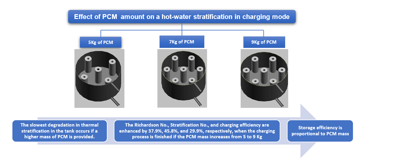
Among the various techniques for enhancing the storage and consumption of energy in a thermal energy storage system, the establishment of thermal stratification in a hot-water container is an effective technology. The current study aims to assess the performance of the thermal stratification for hot-water containers using (ANSYS Fluent) R.1.0, 2022, through the study of the impact of different numbers of paraffin-filled containers, namely 3, 5, and 7, that are equivalent to 5, 7, and 9 kg of paraffin, respectively. To validate the present numerical model, a comparison between the current study results and the experimental findings from the literature was conducted, and the results demonstrated that there was a good approval between these results. The results of this study depict that the profile temperature at the outlet of the container indicates an enhancement in the Richardson number and stratification number by 37.9% and 45.8%, respectively, when the charging process is finished. Furthermore, increasing the number of paraffin-filled containers from 5 to 9 results in a 29.9% improvement in charging efficiency, resulting in an improvement in storage efficiency. Finally, the results have proven that the 3D CFD approach is a highly beneficial tool to assess the effect of PCM mass on stratification performance in a hot-water container.Graphic Abstract
Keywords
Nomenclature
| Cp | Specific heat of PCM (J/kg.K) |
| G | Acceleration of gravity (m/s2) |
| H | Enthalpy (KJ/kg) |
| k | Thermal conductivity (W/m.k) |
| N | Number of grid points |
| m | Mean |
| P | Pressure |
| Ri | Richardson number |
| St. | Stratification number |
| t | Time (s) |
| T | Temperature (°C) |
| Tref | Reference temperature (°C) |
| u | Velocity (m/s) |
| Greek Symbols | |
| μ | Dynamic viscosity (kg/m s) |
| β | Thermal expansion coefficient (1/k) |
| ρ | Density (kg/m3) |
| Λ | Local liquid fraction |
| E | Efficiency |
| Superscripts | |
| avg | Average |
| ch | Charging |
| f | Fluid |
| HTF | Heat transfer fluid |
| HWS | Hot water storage |
| in | Inlet |
| ini | Initial |
| L | Liquid |
| p | PCM |
| ref | Reference |
| S | Solid |
| TES | Thermal energy storage |
Among the various techniques for enhancing the storage and consumption of energy in a thermal energy storage system, the establishment of thermal Stratification in a hot-water container is an effective technology. The current study aims to assess the performance of the thermal Stratification for hot-water containers using (ANSYS Fluent) R.1.0, 2022, through the study of the impact of different numbers of paraffin-filled containers, namely 3, 5, and 7, that are equivalent to 5, 7, and 9 kg of paraffin, respectively. To validate the present numerical model, a comparison between the current study results and the experimental findings from the literature was conducted, and the results demonstrated that there was a good approval between these results. The results of this study depict that the profile temperature at the outlet of the container indicates an enhancement in the Richardson number and stratification number by 37.9% and 45.8%, respectively, when the charging process is finished. Furthermore, increasing the number of paraffin-filled containers from 5 to 9 results in a 29.9% improvement in charging efficiency, resulting in an improvement in storage efficiency. Finally, the results have proven that the 3D CFD approach is a highly beneficial tool to assess the effect of PCM mass on stratification performance in a hot-water container.
The dominant feature in the combination of the most highly efficient and renewable technologies is their intermittency. These systems and technologies are commonly used to meet society’s energy needs, particularly in light of the environmental challenges society faces (Ravestein et al. [1]). The term “intermittency” in the context of thermal energy systems (TES) refers to the deviation in the energy quantity and time-based distribution of the thermal requirements and the resource provided, such as space heating demand and/or domestic hot water (Campos-Celador et al. [2]). For example, solar irradiance in the solar system is typically unavailable throughout all periods that need thermal energy, whereas units with co-generation provide operation strategies that do not typically follow thermal demands. To avoid that intermittency, it was proposed and investigated to incorporate PCM into water storage tanks in order to enhance heat capacity. Kutlu et al. [3] minimized tank volume, lengthen effective heat discharge time and improve thermal Stratification. Thermal Stratification, which produces a difference in the container’s cold and hot fluid densities, is a powerful method to enhance the charging/discharging efficiency of the TES container. There is a large quantity of published studies dealing with the analysis and design of home hot-water units [4–8].
Several researchers have numerically investigated Stratification’s performance for thermal energy storage tanks with and without the PCM. Sharp et al. [9] investigated the comparative benefits of a stratified and a container in a solar home hot-water system and evaluated their differences. They found that the stratification performance is 5%–15% higher than a mixed TES system. Ramana et al. [10] numerically evaluated the stratification performance during the charging operation for the hot-water container integrated with the PCM; the commercial Computational Fluid Dynamics (CFD) software (ANSYS-FLUEN) has been utilized to expect and analyze the stratification behavior for both systems. The results established that the stratification performance of PCM packed storage systems achieves a significant improvement compared with that of sensible heat storage systems. Kong et al. [11] numerically validated with experimental data investigation the influence of cylinder with openings equipped inside heat water container on the stratification performance during charging operation. The CFD with ANSYS CFX was used to model and simulate the three-dimensional model of thermal container. The results illustrated that the cylinder integrated in the container acts as a consistent diffuser, causing thermal Stratification of the water in the container. Additionally, the stratification efficiency increases with the charge process reach to 75.8% after 7000 s of simulation. Kumar et al. [12] studied experimentally the influence of the accumulation of PCM encased in spherical capsules located in a cylindrical container with 115 L at different inlet temperatures and heat transfer fluid flow rates on stratification behavior. The results indicate that the Stratification was enhanced in a sensible TES system for all the heat transfer fluid flow rates examined and at the lower HTF inlet temperature. However, adding PCM capsules increased the stratification range when the temperature difference between PCM melting temperature and the inlet heat transfer fluid was increased. In this study, Majumdar et al. [13], a unique numerical model was placed to evaluate the performance of thermal Stratification in a hot-water container. The melting point of PCM plays an essential role on the range of stratification and storage efficiency. Bai et al. [14] numerically evaluated the degree of thermal Stratification in a cylindrical water container to create an effective and simple approach to model the effects of heat loss in a container when the container is not being charged or discharged. The results reveal that natural convection generates a boundary layer along the sidewall of the cylindrical container, which forces cooled water down the side. A container with a 1:1 aspect ratio has the highest energy efficiency and maximum exergy efficiency. In Wang et al. [15], the CFD model of the heating container was created to predict the discharge mode by using ANSYS, FLUENT 18. The numerical study analyzed the location of the PCM influence on thermal Stratification for numerous flow rates. The results demonstrated that the equalizer effectively improves the thermal Stratification in the heat container equipped with PCM and steadies the heat output performance of the water container. Wilkc et al. [16] investigated numerically the thermal stratification performance generated in a hot-water container fitted with a three-coil heat exchanger. The results reveal that the buoyant force pushes the water up when the lower coil heats the water in the container. It causes a high mixing of the water in the container and negatively affects the Stratification. İzgi et al. [17] investigated a 3D numerical model utilizing the CFD to simulate and evaluate the influence of PCM on the performance of thermal Stratification in a vertical hot-water container. The results indicated that adding the PCM into a mantled hot-water container raises the outlet temperature and the thermal Stratification.
According to the literature review above, there is little emphasis on the effect of PCM mass on thermal stratification performance in a hot-water container. To backfill this gap, the current study has focused on investigating the effect of paraffin-filled container numbers with radial distribution on stratification performance in a thermal energy container during the charging process in transient mode for 60 min.
Based on the Finite Volume Method (FVM) approach, the case study was modeled and solved. The three-dimensional geometry was completed by utilizing the solid work 2022 software. The numerical calculations of the current study were performed by the ANSYS 22 R1.0 fluent. Furthermore, some assumptions and methodologies were used to reach the numerical solution. These assumptions are used to solve the specificities of thermal Stratification in a hot-water container using the governing equations of transient 3D models.
1. The working liquid (water) is incompressible.
2. The influence of temperature and viscous dissipation on pressure was insignificant.
3. As water’s temperature varied, its thermal properties changed, including density, specific heat capacity, dynamic viscosity, and thermal conductivity.
4. The effect of radiation is negligible.
The thermal stratification features of the hot-container were computed using Navier-Stokes and energy equations, as well as taking gravity into consideration. The following governing equations used in this study [17]:
The momentum equation:
The energy equation:
Enthalpy method is used to solve the phase transformations of the PCMs as follows:
The current study uses the K-ε model to analyze turbulent flow because it produces more reasonable results than other turbulent models [18]. Eqs. (9) and (10) are representing the transport equations for k-ε [19].
The Boussinesq approximation is an approach to solving non-isothermal flow problems as free convection problems. The Boussinesq approximation is used to simplify Eqs. (1)–(4) because they are complicated and extremely coupled to solve [16]. Furthermore, this model is applicable when the temperature difference between the cold and hot fluid zones is low. Eq. (11) can be used to represent the Boussinesq approximation density [18].
As long as the condition is maintained {[β (T – To)] << 1} is satisfied, and the Boussinesq estimate is appropriate. The value of [β (T – To)] in this study is to be 10−4.
In order to examine the transient performance of the hot-water container and to compute the grade of Stratification, a dynamic functioning mode with various heat masses of PCM is considered. This process is simplified and simulated assuming the container is completely insulated and without heat losses to the ambient. The current study considers the process of a HWS container in charging mode. A HWS container filled with cold water and the PCM enclosure are arranged radially during charging, and the PCM is heated by hot water from the water heater. The process of charging is simulated with (5, 7 and 9) kg of PCM functioning at a time. As charging progresses, the hot-water volume within the container rises, and the temperature gradient begins to move in the pivotal direction, separating the warm water from the cold.
The geometry was built using SolidWorks 2022 software; two geometries are built: the first represents the thermal container with a height and diameter of 800 and 400 mm, respectively, as illustrated in Fig. 1a. The second is PCM’s enclosure, which is an aluminum annular pipe with an outer and inner diameter of 60 and 20 mm, respectively, with a height of 600 mm and longitudinal fins (four fins per each pipe), as shown in Fig. 1b. Furthermore, both the container and the PCM’s enclosure have a 2 mm thickness.
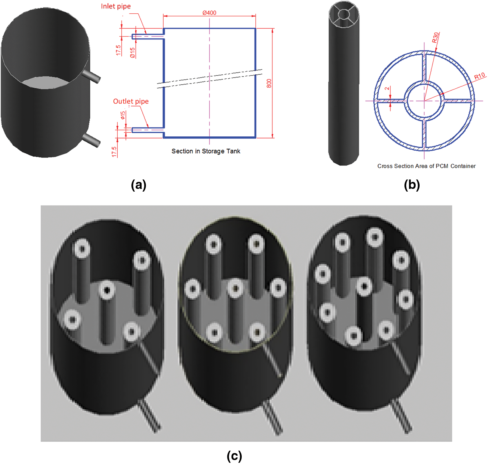
Figure 1: Geometry of current study: (a) Container; (b) PCMs enclosure, (c) PCMs enclosure distribution into the container
Three PCM masses of (5, 7, and 9) kg were adapted to represent the mass ratio of PCM to the water in the container. Each PCM enclosure contains 1 kg of PCM; one is positioned in the center of the container, and the other is equally radially distributed with a 150 mm radius around the container center. The clearance between the container bottom and the enclosure base is 150 mm. Fig. 1c shows the configuration of the PCM enclosures according to the container.
The mesh of the hot-container with PCM enclosures and PCM investigated in the current study is shown in Fig. 2. The structured mesh was generated by the Ansys-fluent program.
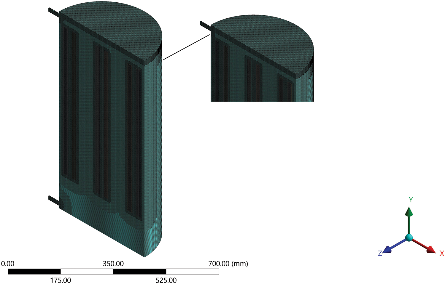
Figure 2: Mesh of case study
Because of the important changes in temperature and the phase change in the PCM, two inflation layers were created to obtain a high-accuracy solution. As shown in Table 1, several number of cells were tested in this study to confirm the sensitivity of mesh cell size in the hot container and PCM. The grid independency error difference should be less than 1%.
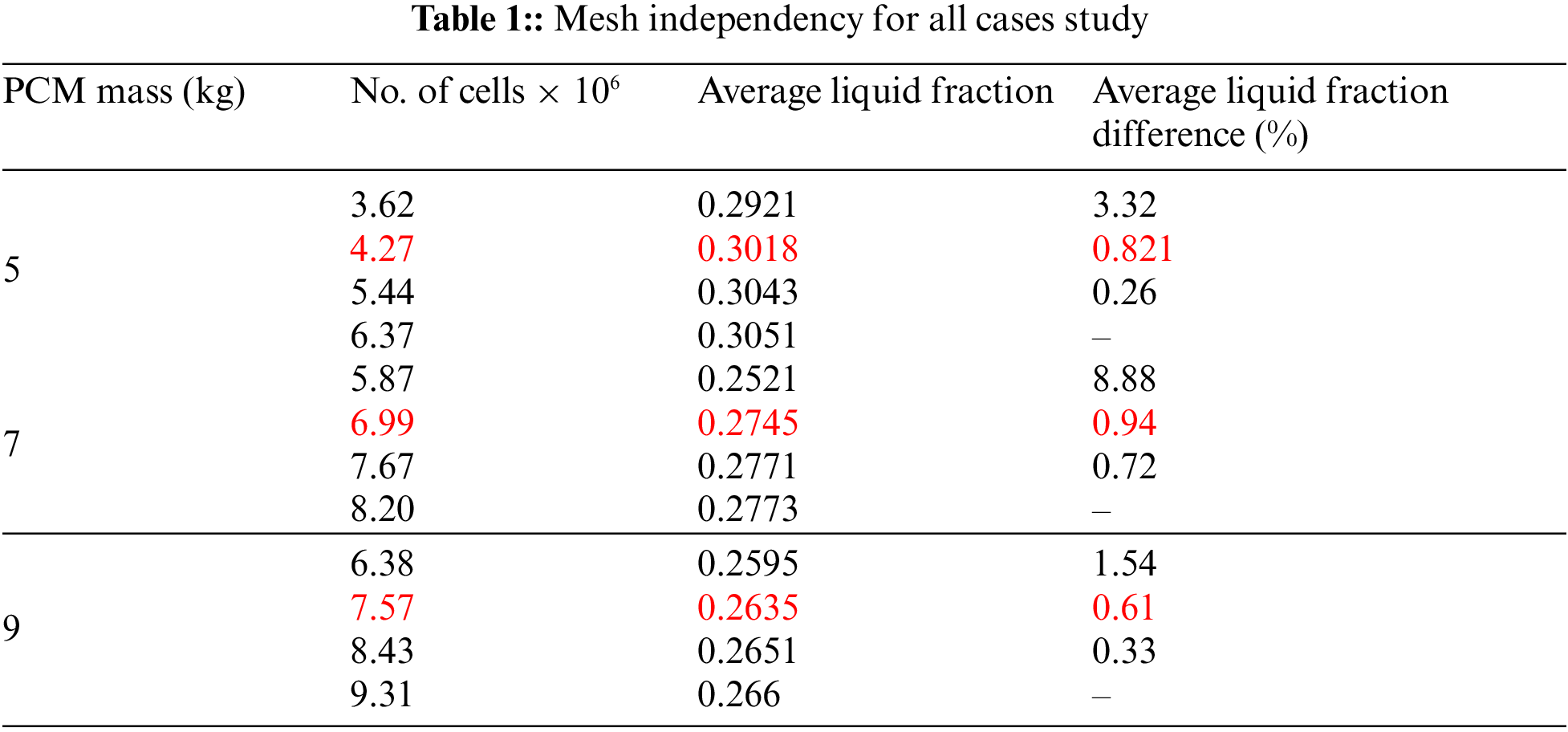
It is clear that the influence of the number of cells on average liquid fraction difference gets very small as an increase in the number of cells. Thus, to save computational work a mesh marked in Table 1 is used with all the case studies.
Table 2 shows the mathematical representation of the boundary conditions for the various operational modes shown in Fig. 3. The inlet (mass flowrate) was 0.033 kg/s with 70°C. The outlet (outflow) represents the boundary condition at the outlet. The temperature of the water in the container was 25°C. The solidification and melting model was activated to study the impact of PCM in the thermal container, and the transient solver was adopted to solve the model. According to the symmetry presented in the geometrical, the symmetry plan was created in the center of the container to reduce the solution time, as shown in Fig. 3. The time step size was 0.025 s, and the total time step was 144000, representing the charging process for 60 min.
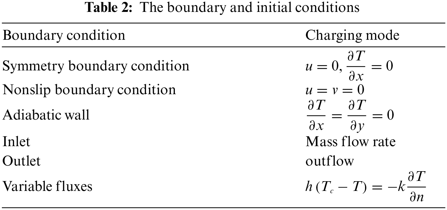
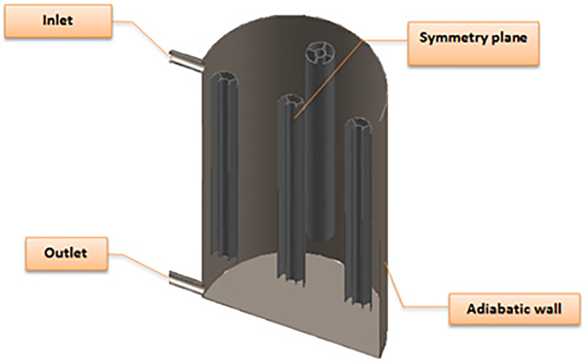
Figure 3: Boundary conditions fitted on geometry of present study
The energy and momentum equation were discretized using the second-order upwind scheme. The convergence tolerances for the continuity, momentum, and energy equations were 10–5, 10–5, and 10–6, respectively.
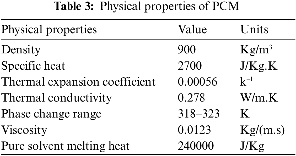
The water and phase change material was treated as Boussinesq materials to ensure the correct solution of non-isothermal flow. The PCM type used in the current study is paraffin wax, and its physical properties are cited in Table 3.
5 Performance Characterization
The Richardson number is utilized to associate the thermal Stratification in the hot-water container in various states, as changeable inlet velocity and/or when fluid flows through the container, during the charging or discharging process [20]. The ratio of the floating force to mixed force ratio is defined as a Richardson number; a large Ri denotes a stratified container, while a small Ri indicates a mixed container. The Ri can be computed by Eq. (12) [21].
The Ri is a
where:
where, Ttp and Tbt represent the water temperature at the upper and lower layers of the TES container, and
The thermal Stratification in a hot-water container is computed by utilizing a dimensionless number, the Stratification number (
where:
where, Tini and Tin represent the initial and inlet HTF temperature, respectively. ‘N’ is the number of nodal points, ‘j’ is the nodal points, so the temperature scales are made, and ‘
The ratio of the instantaneously released or stored energy during the charging process to the highest achievable transfer energy at a given time and mass flow rate of HTF at the storage’s inlet is the charging efficiency [24]. Consequently, Eq. (17) can be used to represent the charging efficiency.
where, Tin and To(t) are the inlet and time variable outlet temperature of the HTF, respectively.
The active energy stored in time (t) to the maximum feasible energy that can be stored in the given time through charging mode and is defined as storage efficiency εst. It can be written as [10]:
where,
6.1 Validation of the Numerical Model
For the CFD model verification, experimental statements from Zachar et al. [25] was utilized to verify the current numerical model. Fig. 4a introduces a schematic container, which was auditioned by Zachar et al. [25]. Simulations were performed at a flow rate of 1.8 l/min with initial and inlet temperatures of 23°C and 44°C, respectively. The temperature along line A in Fig. 4a at time 1500 s during the charging process is employed to compare the qualitative and quantitative results with experimental statements [25]. The numerical simulation results are plotted in Fig. 4b, showing a satisfactory approval between the numerical results and the experimental statements, which are less than 2%.
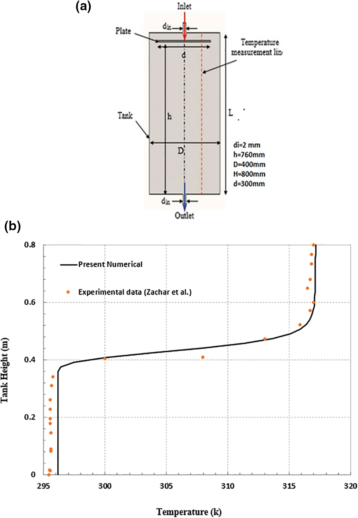
Figure 4: (a) Schematic of container used by Zachar et al. [25], (b) the validation of a numerical model for a hot-water container at time 1500 s
6.2 Parametric Study for Charging Mode
During the charging process, the impact of PCM mass on stratification behavior in a TES container is investigated using PCM masses of 5, 7, and 9 kg at an inlet HTF temperature of 70°C with a flow rate of 2 L/min and water as an HTF. The storage units are placed 50 mm from the container’s top edge. According to the TES container mechanism, the transient outlet temperature profile during the charging period is critical. The range of thermal Stratification inside the container is the temperature difference between the container’s upper and lower layers at any point during the charging period.
Fig. 5a illustrates the variation in the outlet temperature of the HTF with the simulation time of charging mode for three different masses of the PCM. At 33, 25, and 20 min for PCM masses of 5, 7, and 9 kg, respectively, the temperature of HTF at the outlet begins to rise from its initial value of 298 K. A constant flow rate of HTF into a TES container with a smaller PCM mass produces more sensible heat, which takes longer to transfer to the lower layer of the container. As a result, HTF outlet temperature rises later for a smaller PCM mass after PCM melting. A steep rise in the outlet HTF temperature followed the initial rise. Because the content of latent heat energy is lower for a mass of 5 kg, the PCM melts faster than the PCMs with masses of 7 and 9 kg (as shown in Figs. 5b and 5c), and its average liquid fraction reaches 0.99 when the charging mode is in the ending period, compared to 0.96 and 0.95 for the PCMs with masses of 7 and 9 kg, respectively. It can be observed from the figure for the smaller mass after 50 min. when the PCM is melted, the outlet HTF temperature is higher than other studied masses because a greater quantity of heat content is accessible towards the lower layers of the container with a smaller PCM. Finally, from Fig. 5a, the outlet temperature of HTF is found to be 332.98, 331.88, and 328.8 K for the corresponding PCM masses of 5, 7, and 9 kg at 60 min.
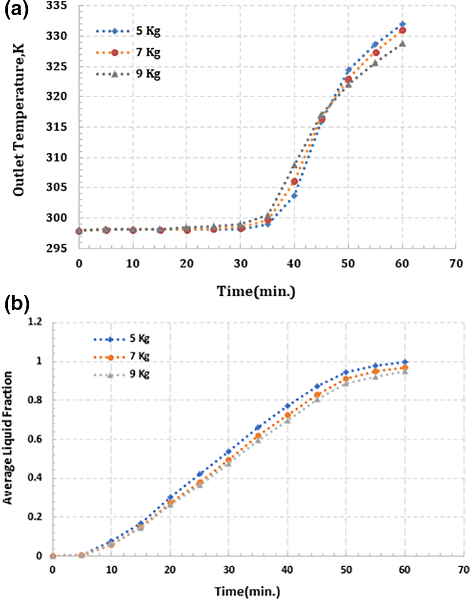
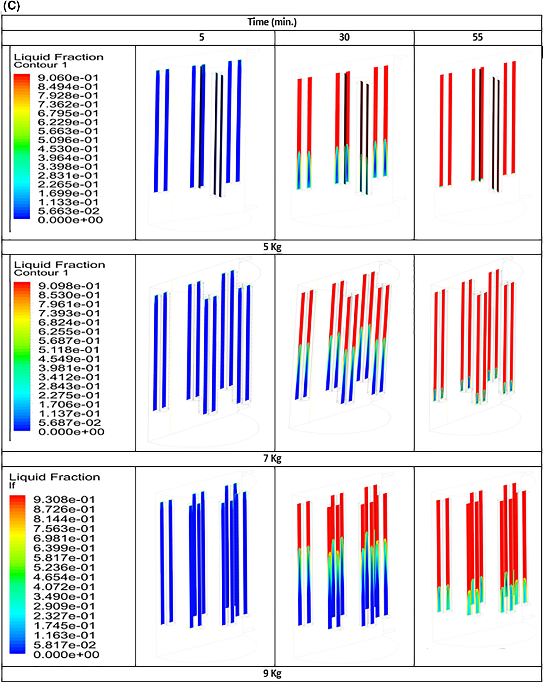
Figure 5: (a) The profile of the outlet temperature of HTF, (b) average liquid fraction of PCM mass, (c) liquid fraction contour of PCM mass with simulation time 60 min
The current numerical investigation focused on the effect of PCM mass (5, 7, and 9) kg on several parametrical factors, such as the Richardson number. The most often used nondimensional stratification performance determination for a TES container is the Richardson number (Ri) [12]. The larger the value of Ri, the best the Stratification. The temperature in the upper layers of the container rises through the initial phase of the charging process because of the sensible heating of the water, solid PCM, and PCM enclosures. As a result, the Richardson number has gradually increased, as demonstrated in Fig. 6, and an earlier reach to the largest value (peak) occurred for higher PCM mass at 30 min of simulation. In addition, it can be detected that, upon reaching its higher value (peak), Ri reductions sharply increase with further heat transfer to the lower of the container due to the increased resistance provided by the melted PCM at the upper zone of the container to any further heat transfer. A higher amount of heat for the smaller PCM mass was diffused towards the lower layers of the container; this led to a reduction in the rate of the Ri number.
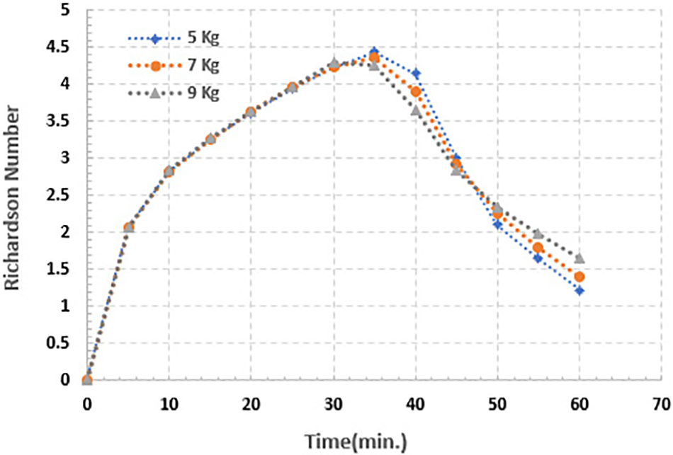
Figure 6: Richardson number for (5, 7 and 9) kg of PCM for simulation time 60 min
As the PCM mass increased and the quantity of HTF (water) in the container decreased, the thermal gradient became more stable along the top zone of the TES container; this refers to minimizing the proportion of heat transfer or spread towards the container’s outlet as a result of keeping a higher amount of heat in the form of latent heat. At the end of the charging period, the values of Ri are found to be 1.226, 1.389, and 1.655 for the PCM masses of 5, 7, and 9 kg, respectively.
Fig. 7 describes the development of the stratification number for the aforementioned PCM mass values over time. For a constant flow rate and constant temperature of the HTF at the container inlet, the stratification number rises uniformly as the charging mode is started and arrives the higher value of 0.9849, 0.9773, and 0.9733 for PCM mass (5, 7, and 9) kg, respectively after 30 min of simulation time. The stratification number peak value is somewhat inversely proportional to the PCM mass because of the TES’s high sensible heat content, which in turn results in a greater thermal gradient extended along the height of the container [12]. It is obvious that when the PCM mass is large, the thermal Stratification in the container occurs quickly because of the heat spread towards the lower zone. Furthermore, the outlet of the container increased as a result of the higher effective thermal diffusivity of TES. A sharp reduction in the stratification number is detected after the higher value (peak), referring to dilapidation in the thermal Stratification, which is principally recognized as the decrease in thermal gradient in the container. For all PCM masses, the profile of the stratification number is found to fall steeper. The PCM at the top zone of the hot-water container begins the melting phase as a result of reaching the melting temperature. The heat transfer from the hot-water flow into the container to the PCM is done as latent heat. The higher PCM mass latently absorbs more energy as heat. Thus, its content of heat is higher. As a result, the thermal stratification degradation is relatively slower because the hot-water container keeps the thermal gradient stable. The results indicated that a higher PCM mass corresponded to a higher stratification number. When the charging period is finished, it is established that the stratification number values are 0.2152, 0.2633, and 0.3138 for the considered PCM masses of 5, 7, and 9 kg, respectively.
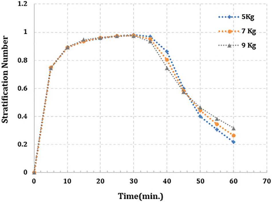
Figure 7: Stratification number for (5, 7 and 9) kg of PCM for simulation time 60 min
Fig. 8 displays the progressive variant of charging efficiency for the TES scheme for numerous PCM masses, with the inlet temperature of the hot-water container being 70°C. For PCM masses of 5, 7, and 9 kg, it is established that the charging efficiency is a stratification number that is directly related to the first half of the charging mode period and that the stratification number reaches near 1 after about 50% of the simulation time. This refers to the fact that the accessibility of sensible heat contained in the thermal energy storage is greater for a smaller PCM mass as the flow rate of HTF is fixed. With the smaller mass of the PCM, the charging efficiency rests higher for a somewhat longer time during the first stage of the charging mode. Following the first high value, there is a dramatic fall in charging efficiency in the next 33% of the charge period. As further heat is transferred to the bottom zone of the container, the charging efficiency decreases. After the acute drop, the charging efficiency rests at its value (εch 31.7%, 26.5%, and 24.4% for PCM masses of 5, 7, and 9 kg, respectively, at the end of the charging mode). It is obvious, near the end of the charging mode simulation, that once the PCM melting phase starts, the remaining charging efficiency calms down, and the higher value is directly proportional to a larger PCM mass because of the absorption of a higher quantity of energy as latent heat.
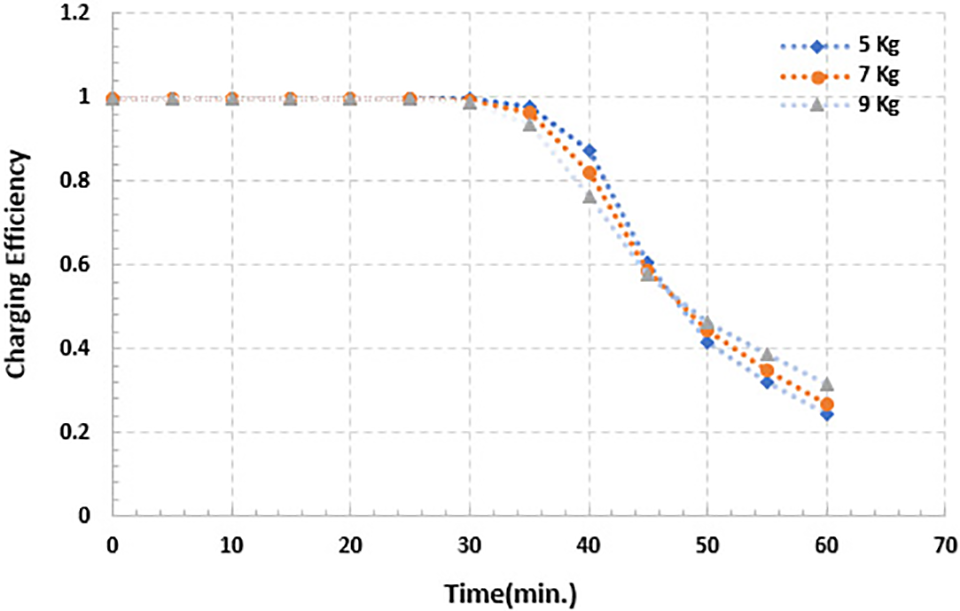
Figure 8: Charging efficiency for (5, 7 and 9) kg of PCM for simulation time 60 min
Fig. 9 depicts the storage efficiency variation with respect to simulation time for different PCM masses. It is obvious that the storage efficiency rises from its initial value (0%) over the charging mode time for all the PCM mass. At the end of the charging mode period, it is found that the storage efficiencies are 96.9%, 95.24%, and 93.3% for PCM 9, 7, and 5 kg, respectively. The storage efficiency is marginally increased for the greater PCM mass of 9 kg, although it is least affected by the change in the PCM mass, as the quantity of accessible energy content in the thermal energy storage (TES) in the collective form is sensible and latent heat raises almost proportionately with the increased PCM mass, thus keeping the average temperature of the hot-water container at a higher level.
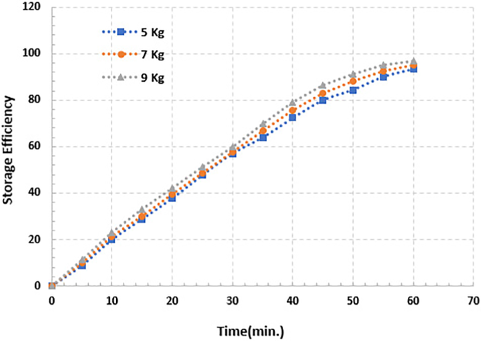
Figure 9: Storage efficiency for (5, 7 and 9) kg of PCM mass for simulation time 60 min
6.2.6 Temperature Distribution
Fig. 10 shows the temperature distribution contour during charging mode with different times of simulation for a container equipped with (5, 7, and 9) kg of PCM. It is obvious that the temperature rises with time, just as with the changing of cold water for hot-water, the water temperature in the container increases with the time of charging; this is identical with the melting process with the PCM. It is obvious that the temperature distribution in a container equipped with 5 kg of PCM is higher than with 7 and 9 kg of the same PCM, because part of the heat transfer from charging hot-water is transferred to the PCM enclosure, and the cold water in the container gains the other if the continued charging mode takes 60 min. As the PCM mass increases, the heat transfer from hot water to the PCM enclosures increases, while the heat gained by cold water in the container decreases, causing a temperature drop in the container’s lower zone, as shown in times 5, 30, and 55 min.
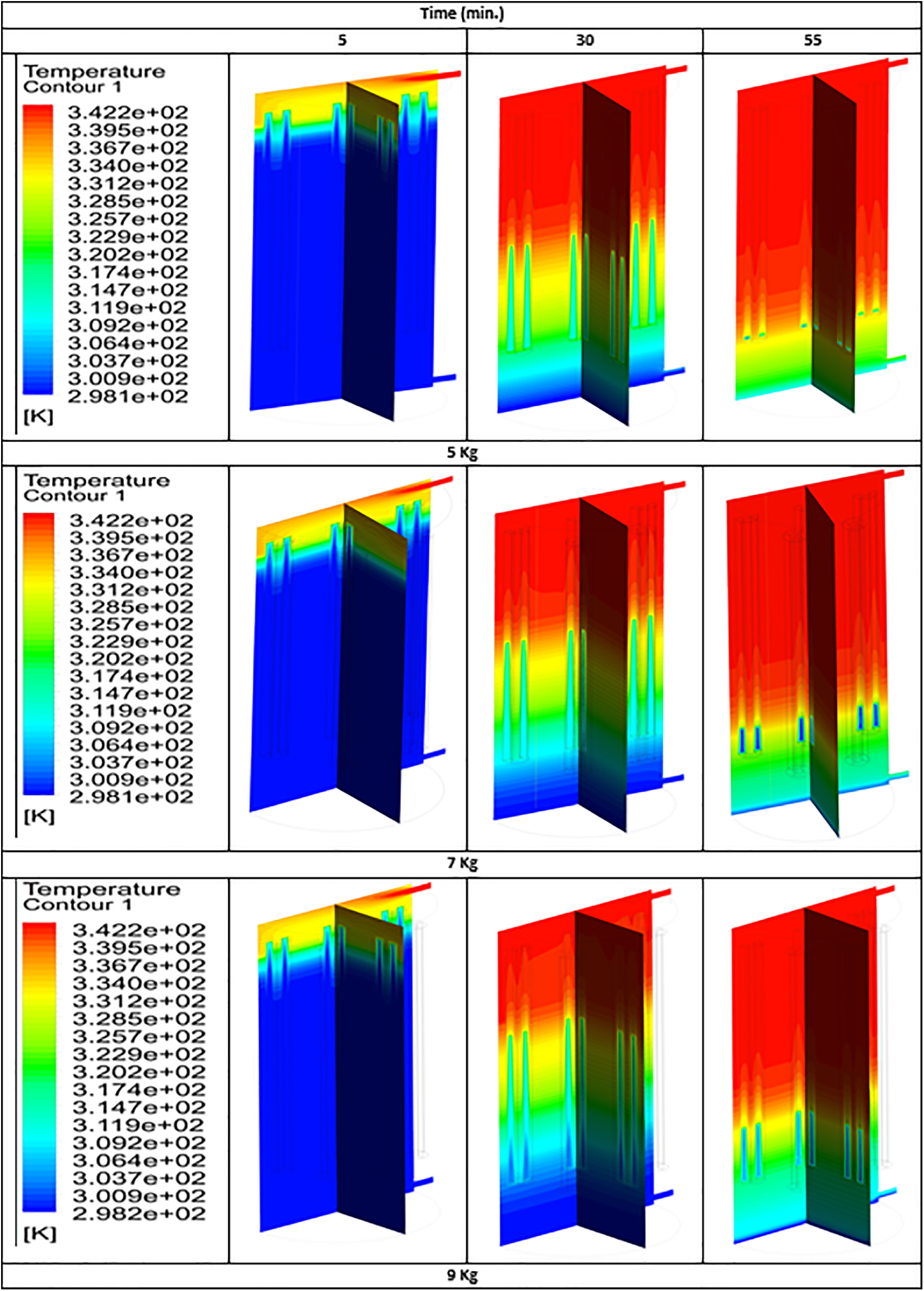
Figure 10: Temperature distribution contour of PCM mass for simulation time 60 min
Thermal Stratification in thermal energy storage (TES) equipped with phase-change-material (PCM) enclosures is investigated for charging mode in the current study. The established numerical model is verified by utilizing published experimental data, and a practically good agreement is found. Numerous performance parameters are utilized to establish the influence of PCM mass on the TES container’s thermal stratification performance. The numerical investigation helped conclude several of the noticeable results:
• During charging, the thermal container’s upper zone of PCM enclosures affects stratification performance. Higher stratification number and Richardson number values occur slightly earlier for higher PCM mass. The slowest degradation in thermal Stratification in the container occurs if a higher mass of PCM is provided.
• The Richardson number, stratification number, and charging efficiency are enhanced by 37.9%, 45.8%, and 29.9%, respectively, when the charging process is finished if the PCM mass increases from 5 to 9 kg.
• Storage efficiency is proportional to PCM mass; as PCM mass increases, so does storage efficiency. The maximum value of efficiency occurs at the end of the charging process (after 60 min).
• The melting process of PCM increases with time; thus, the liquid fraction increases according to the time of the charging process but does not reach a fully liquid state for all of the mass of PCM.
Finally, the analysis approaches utilized demonstrate most enable and use the results to be compared and introduced in a new method.
Acknowledgement: The authors would like to thank Mustansiriyah University www.uomustansiriyah.edu.iq in Baghdad-Iraq for its support in the present study.
Funding Statement: The authors received no specific funding for this study.
Author Contributions: The authors confirm contribution to the paper as follows: study conception and design: A.H.; data collection: B.F.; analysis and interpretation of results: A.H., B.F.; draft manuscript preparation: A.A. All authors reviewed the results and approved the final version of the manuscript.
Availability of Data and Materials: The data are available when requested.
Conflicts of Interest: The authors declare that they have no conflicts of interest to report regarding the present study.
References
1. Ravestein, P., van der Schrier, G., Haarsma, R., Scheele, R., van den Broek, M. (2018). Vulnerability of European intermittent renewable energy supply to climate change and climate variability. Renewable and Sustain Energy Reviews, 97, 497–508. [Google Scholar]
2. Campos-Celador, Á., Diarce, G., Larrinaga, P., García-Romero, A. M. (2020). A simple method for the design of thermal energy storage systems. Energy Storage, 2(6), e140. [Google Scholar]
3. Kutlu, C., Zhang, Y., Elmer, T., Su, Y., Riffat, S. (2020). A simulation study on performance improvement of solar assisted heat pump hot water system by novel controllable. Renewable Energy, 152, 601–612. [Google Scholar]
4. Shukla, R., Sumathy, K., Erickson, P., Gong, J. (2013). Recent advances in the solar water heating systems: A review. Renewable and Sustainable Energy Reviews, 19(3), 173–190. [Google Scholar]
5. Armstrong, P., McCulloch, M. (2014). Distributed energy storage using domestic hot-water tanks and a novel thermocline sensor. 5th IEEE PES Innovative Smart Grid Technologies Conference Europe (ISGT-Europe), Istanbul. [Google Scholar]
6. Bouhal, T., Agrouaz, Y., Allouhi, A., Kousksou, T., Jamil, A. et al. (2017). Impact of load profile and collector technology on the fractional savings of solar domestic water heaters under various climatic conditions. International Journal of Hydrogen Energy, 42(18), 245–258. [Google Scholar]
7. Hasan, S., Azher, M., Laith, J. (2021). Performance evaluation of a solar water heater integrated with built-in thermal energy storage via porous media. Frontiers in Heat and Mass Transfer, 17, 1–7. [Google Scholar]
8. Poyyamozhia, N., Karthikeyan, A. (2022). Enhancement of solar pond effectiveness through addition of PCM to low convective zone. Frontiers in Heat and Mass Transfer, 18, 13. [Google Scholar]
9. Sharp, M. K., Loehrke, R. I. (1979). Stratified thermal storage in residential solar energy applications. Journal of Energy, 3(2), 106–113. [Google Scholar]
10. Ramana, A. S., Venkatesh, R., Antony Aroul Raj, V., Velraj, R. (2014). Experimental investigation of the LHS system and comparison of the stratification performance with the SHS system using CFD simulation. Solar Energy, 103(8), 378–389. [Google Scholar]
11. Kong, L. K., Yuan, W. X., Zhu, N. (2016). CFD simulations of thermal stratification heat storage water tank with an inside cylinder with openings. Procedia Engineering, 146(8), 394–399. [Google Scholar]
12. Kumar, G. S., Nagarajan, D., Chidambaram, L. A., Kumaresan, V., Ding, Y. et al. (2016). Role of PCM addition on stratification behavior in a thermal tank–an experimental study. Energy, 115, 1168–1178. [Google Scholar]
13. Majumdar, R., Saha, S. K. (2019). Effect of varying extent of PCM capsule filling on thermal stratification performance of a tank. Energy, 178(17), 1–201. [Google Scholar]
14. Bai, Y. K., Yang, M., Wang, Z. F., Li, X. X., Chen, L. F. (2019). Thermal stratification in a cylindrical tank due to heat losses while in standby mode. Journal of Energy Storage, 185, 222–234. [Google Scholar]
15. Wang, Z. L., Zhang, H., Dou, B. L., Zhang, G. H., Wu, W. D. (2019). Influence of inlet structure on thermal stratification in a heat tank with PCMs: CFD and experimental study. Applied Thermal Engineering, 162, 114–151. [Google Scholar]
16. Wilkc, J., Bałon, P., Smusz, R., Rejman, E., Świątoniowski, A. et al. (2020). Thermal stratification in the tank. 23rd International Conference on Material Forming, vol. 47, pp. 998–1003. University of Cottbus, Germany. [Google Scholar]
17. İzgi, B., Arslan, M. (2022). Effect of phase change material on thermal stratification of solar hot-water tank with a mantle: A numerical analysis. Journal of Energy Storage, 105078. [Google Scholar]
18. Abdelhak, O., Mhiri, H., Bournot, P. (2015). CFD analysis of thermal stratification in domestic hot-water container during dynamic mode. Building Simulation, 8(4), 421–429. [Google Scholar]
19. ANSYS Inc. (2009). Ansys fluent 14.0 theory guide. Canonsburg, PA, USA: ANSYS Inc. [Google Scholar]
20. Oró, E., Castell, A., Chiu, J., Martin, V., Cabeza, L. F. (2013). Stratification analysis in packed bed thermal energy storage systems. Applied Energy, 109(2), 476–487. [Google Scholar]
21. Zurigat, Y. H., Liche, P. R., Ghajar, A. J. (1991). Influence of inlet geometry on mixing in thermocline thermal energy storage. International Journal of Heat and Mass Transfer, 34(1), 115–125. [Google Scholar]
22. Ghajar, A. J., Zurigat, Y. H. (1991). Numerical study of the effect of inlet geometry on stratification in thermal energy storage. Numerical Heat Transfer, Part A: Applications, 19(1), 65–83. [Google Scholar]
23. Fernández-Seara, J., Uhía, F. J., Sieres, J. (2007). Experimental analysis of a domestic electric hot-water container. Part II: Dynamic mode of operation. Applied Thermal Engineering, 27(1), 137–144. [Google Scholar]
24. Panthalookaran, V., Heidemann, W., Müller-Steinhagen, H. (2007). A new method of characterization for stratified thermal energy stores. Solar Energy, 81(8), 1043–1054. [Google Scholar]
25. Zachár, A., Farkas, I., Szlivka, F. (2003). Numerical analyses of the impact of plates for thermal stratification inside a storage tank with upper and lower inlet flows. Solar Energy, 74(4), 287–302. [Google Scholar]
Cite This Article
 Copyright © 2023 The Author(s). Published by Tech Science Press.
This work is licensed under a Creative Commons Attribution 4.0 International License , which permits unrestricted use, distribution, and reproduction in any medium, provided the original work is properly cited.
 Downloads
 Citation Tools