
 Submit a Paper
 Propose a Special lssue
 Open Access
ARTICLE

Numerical Studies on Thermal and Hydrodynamic Characteristics of LNG in Helically Coiled Tube-in-Tube Heat Exchangers
School of Mechanical and Electronic Engineering, Shandong Jianzhu University, Jinan, 250101, China
* Corresponding Author: Fayi Yan. Email:
Frontiers in Heat and Mass Transfer 2024, 22(1), 287-304. https://doi.org/10.32604/fhmt.2023.045038
Received 15 August 2023; Accepted 02 November 2023; Issue published 21 March 2024
 View Full Text
 Download PDF
Abstract
As compact and efficient heat exchange equipment, helically coiled tube-in-tube heat exchangers (HCTT heat exchangers) are widely used in many industrial processes. However, the thermal-hydraulic research of liquefied natural gas (LNG) as the working fluid in HCTT heat exchangers is rarely reported. In this paper, the characteristics of HCTT heat exchangers, in which LNG flows in the inner tube and ethylene glycol-water solution flows in the outer tube, are studied by numerical simulations. The influences of heat transfer characteristics and pressure drops of the HCTT heat transfers are studied by changing the initial flow velocity, the helical middle diameter, and the helical pitch. The results indicate that different initial flow velocities in the inner tube and the outer tube of the HCTT heat exchanger have little influence on the secondary flow of the fluid in the helical tubes, and the overall flow characteristics tend to be stable. The smaller helical middle diameter of the HCTT heat exchanger leads to the shorter fluid flow length, the smaller resistance along the tubes and the increase of initial pressure under the condition of constant inlet velocity, which promotes the occurrence of secondary flow. The axial flow of fluid promotes the destruction of heat transfer boundary layer and gains strength of the turbulence and heat transfer efficiency. With the increase of the helical pitch of the HCTT heat exchanger, the turbulent intensity and the heat transfer efficiency are also increased. Moreover, the improvement of the flow state of the HCTT exchanger in a longer helical pitch also enhances the heat exchange efficiency.Keywords
Nomenclature
| A | Area, mm2 |
| cp | Constant pressure specific heat capacity, J (/kg·K) |
| D | Middle diameter, mm |
| di | Inner tube diameter, mm |
| E | Energy, J |
| f | Friction coefficient, N/m2 |
| lh | Helix length, mm |
| L | Coil pitch, mm |
| Nu | Nusselt number |
| p | Pressure, MPa |
| Pr | Prandtl number |
| Re | Reynolds number |
| T | Temperature, K |
| u | Velocity, m/s |
| Greek Symbols | |
| Vapor volume fraction | |
| ρ | Density, kg/m3 |
| μ | Dynamic viscosity, Pa·s |
| Kinematic viscosity, m/s2 | |
| Abbreviation | |
| HCTT | Helically coiled tube-in-tube heat exchanger |
Helically coiled tube-in-tube heat exchangers are widely applied in engineering fields such as refrigeration, air conditioning systems, chemical engineering, medical equipment and solar concentrators because of their compact structures and excellent heat transfer performances. Tube-in-tube heat exchangers with different structures, working fluids and boundary conditions have different heat exchange efficiencies. In recent years, the research on tube-in-tube heat exchangers has received continuous attention and achieved significant results [1–4]. However, the working fluids of this kind of heat exchanger are mostly air, water, CO2, R-134A, R-600a, etc. The thermal-hydraulic research of LNG as the working fluid in HCTT heat exchangers is rarely reported. In LNG vehicles, the HCTT heat exchangers are important components for LNG gasification and cold energy recovery. To study the thermal and hydrodynamic characteristics of LNG in helically coiled tube-in-tube heat exchangers has great significance.
In general, the tube-in-tube heat exchanger is designed as a spiral structure to generate centrifugal force through the curvature of a coiled tube and make secondary flow in the process of fluid movement under the guidance of centrifugal force so as to raise the heat transfer efficiency. Elattar et al. [5] performed the CFD simulations of multi tubes in tube helically coiled heat exchangers, and the influences of different structure parameters on fluid flow and heat transfer were obtained. Liu et al. [6] proposed a novel technical solution for HCTT heat exchangers with a double cooling source to obtain regeneratively cooled air for advanced aero engines. Liu et al. [7] presented the testing of an HCTT heat exchanger for a cooled cooling air system by experimental method. Cao et al. [8] investigated the entropy generation during R134a flow condensation inside an HCTT heat exchanger, and the heat transfer and pressure drop contributions to entropy generation are assessed and compared.
To improve the heat exchange efficiency, HCTT heat exchangers are usually added with spiral grooves or inner corrugated pipes. On the one hand, spiral grooves or inner corrugated pipes can achieve surface roughening of the internal thread of the pipe so that the heat transfer boundary layer is torn or even destroyed during the fluid flow process. On the other hand, fluid resistance near the spiral grooves causes separation vortexes in the heat transfer boundary layer, which strengthens the radial mixing of the fluid and decreases the thermal resistance of the boundary layer. Wang et al. [9] analyzed the change and trend of the local heat transfer in the double pipe heat exchanger whose outer tube is a helically corrugated tube. The optimal shell diameter of the helical heat exchanger with low-pressure drop and high heat transfer coefficient was obtained. Verma et al. [10] investigated the effects of the pitches and depths of the corrugated pipes on the heat transfer coefficient and Nusselt number with various Reynolds numbers and mass flow rates. Zhang et al. [11] got the variation rule of the influence of various spherical corrugations geometrical structures on the flow and heat transfer performance of helically coiled-tube heat exchangers by numerical simulation. Fouda et al. [12] compared the heat transfer performances between the double concentric tube helically coiled heat exchanger and the multi tubes of straight tube heat exchanger.
Research on HCTT heat exchangers is mostly carried out by numerical simulations. Regarding the model of numerical calculation, Huang et al. [13] used the concept of segment insertion and subdivision to track the phase change point and presented a generalized finite volume coaxial heat exchangers model. Wang et al. [14] investigated the hydraulic and thermal performance in the tube-side of helically coiled-twisted trilobal tube heat exchanger. Mahdi et al. [15] built a numerical model during the melting of phase change materials to evaluate latent heat storage design. Ndiaye [16] obtained a transient computation model aimed at a refrigerant-to-water helically coiled double tube with corrugations in the inner tube. Abu-Hamdeh et al. [17] studied a new kind of HCTT heat exchanger through numerical calculation, in which the effects of the Reynolds number, Nusselt number, friction coefficient, etc., were studied. Zhang et al. [18] took the backfill of the tubular heat exchanger as the research object, and the heat storage process was simulated using a numerical method.
Working fluids in HCTT heat exchangers are important factors affecting the heat transfer effect. Generally, the working fluids include air, water, R-134A, HFC134-A, R-600a, etc. Fsadni et al. [19] reviewed the main findings of working fluids in HCTT heat exchangers, including steam-water, R-134a air–water nanofluid, etc. Solanki et al. [20] studied the influences of the mass flux, temperature and vapor quality, etc., on the heat transfer coefficient of R-600a in smooth and dimpled helical coil tubes at different initial temperatures and mass flow conditions. Dubba et al. [21] investigated the heat transfer process of R-600a in a helically coiled tube heat exchanger. Wongwises et al. [22] used pure HFC-134a as a working medium to experimentally study the two-phase heat transfer and pressure drop characteristics of smooth HCTT heat exchangers. Zhao et al. [23] optimized the heat exchanger effectiveness and pressure drop of the low-pressure side to meet the requirements of the 1.8 K hybrid cryocooler with He-4 as the only working medium. Mukesh Kumar et al. [24] reviewed the research results and observation results of an HCTT heat exchanger, in which nanofluid was the working fluid. Huminic et al. [25] studied the heat transfer and entropy production of different types of nanofluids in HCTT heat exchangers.
Nowadays, HCTT heat exchanger research has gradually expanded to the engineering field. Zhou et al. [26] studied different heat utilization in winter and heat dissipation in summer and analyzed the factors and rules that affect the thermal transfer effect of surface water source heat pump multi-row HCTT heat exchanger. Kumar et al. [27] studied the effects of shot peening on heat transfer, exergy analysis, and pressure drop in the HCTT heat exchanger, which was applied in the solar energy industry. Zhao et al. [28] investigated the transient behavior of ground-coupled heat pump systems with spiral-tube heat exchangers. Mashoofi et al. [29] introduced a technique for HCTT heat exchangers with or without turbulators and experimentally investigated the effects of the above turbulators on thermal and friction characteristics. In addition, many scholars [30,31] have conducted research on HCTT heat exchangers in Joule-Thomas cryocoolers.
In the presented work, LNG and ethylene glycol-water solution are used as the working fluid. By numerical calculations, the effects of different helical intermediate diameters and helical pitches on the flow and heat transfer characteristics of HCTT heat exchangers under different initial conditions so as to provide a theoretical basis for the optimization of the design of HCTT heat exchangers.
2 Modeling of HCTT Heat Exchangers
The geometric model of the HCTT heat exchanger is shown in Fig. 1. The ethylene glycol-water solution flows in the outer tube (called the outer tube), and LNG flows in the inner tube (called the inner tube). The heat transfer of the two working fluids is countercurrent heat transfer with a large temperature difference. The approximate calculation formula of heat exchange surface area St and helical length of heat exchanger Ct is:
where n is the number of turns of the helical tubes, D is the middle diameter, mm; L is the pitch, mm; di is the diameter of the inner tube, mm.
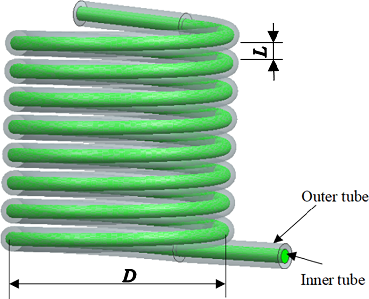
Figure 1: The HCTT heat exchanger geometric model
As shown in Fig. 1, the inner tube of the HCTT heat exchanger is made of copper, the outer diameter of which is 12 mm, and the wall thickness is 1 mm. The outer tube is made of cold rolled carbon, of which the outer diameter is 19 mm, and the wall thickness is 1.5 mm.
The heat exchange process is carried out in the counter-current operation mode, LNG flows in the inner tube, and the glycol aqueous solution flows in the outer tube. In this study, an eight-turn coil tube (n = 8) is used, and the distance between two adjacent turns is called the coil pitch L. The range of L is 15 to 20 mm.
3 Mathematical Formulation and Computational Methodology
The outer wall surface of the HCTT heat exchanger is usually assumed to be an adiabatic surface. The heat exchange between the refrigerant and the outer wall surface is ignored. The ethylene glycol-water solution is in a single state. In the calculation process, the following assumptions are made about the ethylene glycol-water solution:
The fluid is Newtonian, incompressible, isotropic and continuous;
The viscous dissipation is ignored;
Gravity is ignored;
No heat leakage around;
The heat transfer only mainly occurs in the tube, and the axial heat exchange inside the HCTT heat exchanger is ignored.
In the HCTT heat exchanger, heat conduction and forced convection begin to occur at the inlet of the tubes, so both the cold fluid and the hot fluid have a certain turbulent intensity, and the fluids flow and heat exchange rapidly develop downstream of the tubes. In fact, in the HCTT heat exchanger, secondary flow is generated by the flowing vortex due to the structure of the helical coil. The three-dimensional governing equations of the turbulent flow and heat transfer of the HCTT heat exchanger are described in the main Cartesian system in the form of tensor, as shown below:
Continuity equation:
Momentum equation:
Energy equation:
In Eqs. (3)–(5), ρ is the fluid density, kg/m3; ū is the velocity vector, m/s; T is the temperature, K; p is the pressure, Pa; cp is the constant pressure specific heat capacity, J (/kg·K); μ is the dynamic viscosity, Pa·s; E is the total energy, which is described as follows:
The inlet and outlet pressure drop ∆p are as follows:
where pin, pout are the pressure of the inlet and outlet, MPa.
3.2 Turbulence Model Selection and Validation
The k-ε model is based on the original Reynolds average Navier-Stokes equation and the observation of the change of the flow field with time, including local small oscillations. The other equations about the turbulent flow energy k and the turbulent flow energy dissipation rate ε (epsilon) are used to increase the turbulence variable. Compared with other turbulence models, the k-ε model accurately predicts curved and rotating flows and has a good convergence rate and low memory requirements. In addition, k-ε presents the preeminent ability to obtain the average flow of complex structures. The transport equation of turbulent flow energy k:
ε equation:
where k is turbulent flow energy:
ε is turbulent flow energy dissipation rate:
where l is large eddy scale, Prk is 1.0, Prε is 1.3, cε1 is 1.44, cε2 is 1.93, cε3 is −1.0.
3.3 Boundary Conditions and Mesh Independence Test
The numerical simulation process of the flow of two non-isothermal fluids is mainly achieved through the heat exchange between the walls of the inner tube, so the calculation settings require that the heat can flow out through the wall so that the calculation of convective heat transfer no longer needs to manually set convection heat transfer coefficient. The interior wall built in Fluent makes the interface of two types of fluids merge. It is believed that there is no thermal resistance between the two fluids because the wall thickness of the inner tube is only 1 mm, and the material is copper. The velocity condition is set to the flow condition of the inlet of the heat exchange tube. The flow condition of the outlet is set to the pressure outlet, and the reflow rate is 0. Ethylene glycol-water solution and LNG are considered incompressible fluids, and wall treatment is achieved through the two-fluid calculation model built into Fluent. The grid division for the HCTT heat exchanger can be seen in Fig. 2.

Figure 2: Numerical calculation model of heat exchanger
The flow area is divided by the unstructured grids, the boundary layer grid is locally refined, and the low Reynolds number formula is used near the wall surface to completely decompose the velocity distribution into the wall. The boundary layer is set to 8 layers, which can be seen in Fig. 3.
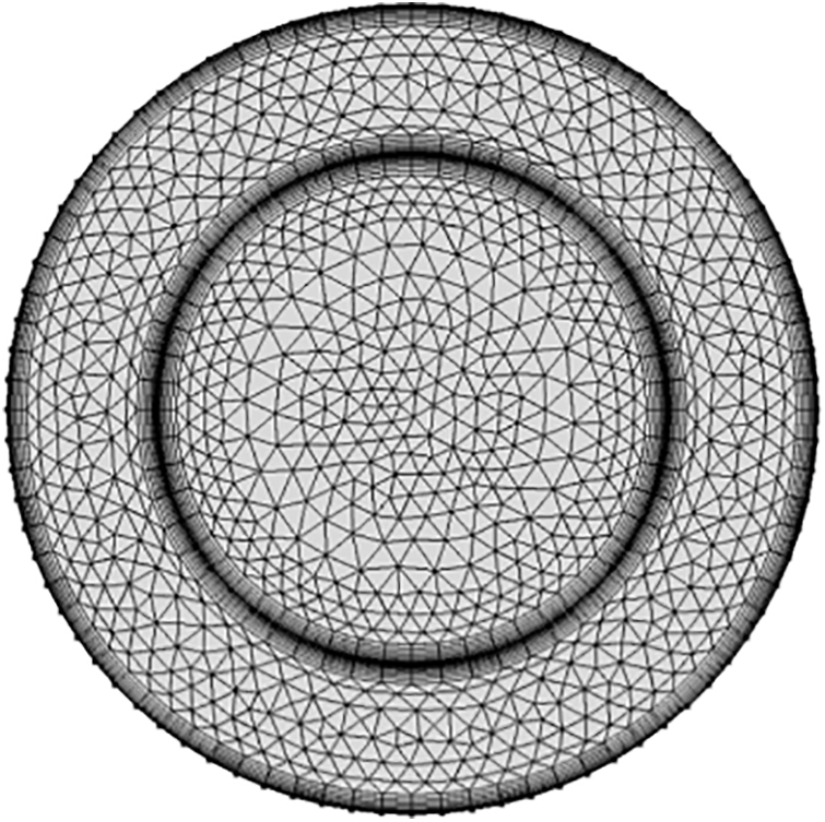
Figure 3: Boundary layer refinement
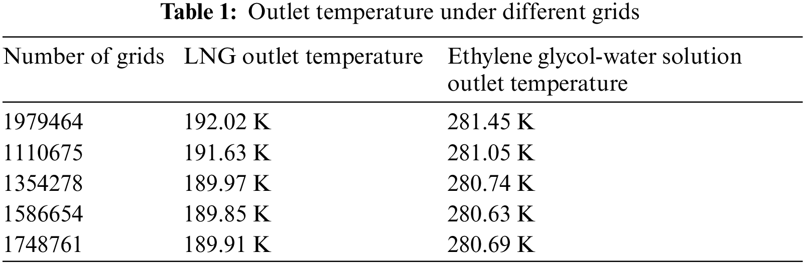
To ensure the accuracy of the calculation, the grid independence of the model is verified. The temperature of the cold and hot fluids in the inner and outer tubes is obtained by calculating four different numbers of grids. As shown in Table 1, for various amounts of grids, when the amount of grids is 1354278, the fluid temperature difference in the inner and outer pipes is the smallest. Therefore, the amount of these grids is adequate to obtain accurate results. Consequently, the grid number 1354278 has grid independence and is used in current numerical simulations.
3.4 Numerical Method and Validation
The second-order upwind style is adopted for the spatial dispersion to ensure the calculation accuracy, the iterative algorithm adopts the improved SIMPLEC algorithm, and the residual accuracy is controlled to 1e-5. The ethylene glycol-water solution flows in the outer tube of the HCTT heat exchanger, and the LNG flows in the inner tube. This study uses the Mixture mixed-phase model for the numerical calculation of multiphase flow. The mass transfer equation is as follows:
where v is vapor phase,
This model belongs to the Euler method, but the small slip of the interphase velocity is considered. The reaction between two phases in multiphase flow includes momentum exchange and chemical reaction. The inner tube of the HCTT heat exchanger is only involved in the phase change reaction of LNG. There is no chemical reaction between gaseous and liquid LNG. Therefore, the momentum exchange between the two phases should be mainly considered. The evaporation-condensation model is used to calculate the momentum exchange between the two phases.
The software FLUENT is used for numerical simulation in this paper. The fluid inside the heat exchanger tube is low-temperature LNG, the inlet boundary condition is the velocity inlet, the normal velocity is 1 m/s, and the inlet fluid temperature is 92 K; The outlet is a natural outflow, with a pressure of 0 and a temperature outlet as outflow; The wall of the heat exchanger is made of structural steel with a wall thickness of 1 mm. To calculate the forced convection heat transfer effect between the inner and outer walls of the heat exchanger, it is necessary to consider that it is a heat flow wall.
The main component of LNG is methane, and its physical properties are the parameters of methane during calculation. The physical parameters of methane are:
In order to verify the accuracy of the numerical calculation method, numerical simulation is carried out according to the experimental conditions of the literature [32]. Fig. 4a shows the influence of different mass flow rates on the local heat transfer coefficient under a heat flux of 12 kW/m2. The horizontal axis represents the local heat transfer coefficient measured in the experiment, the vertical axis represents the number of experiments, and the four colors represent the measurements made under four sets of mass flow rates. In order to avoid sampling errors, the existing 10 experiments have measured the heat transfer coefficient under four sets of mass flow rates (measured values: 51.6, 104.86, 154.84 and 199.23 kg/(m2
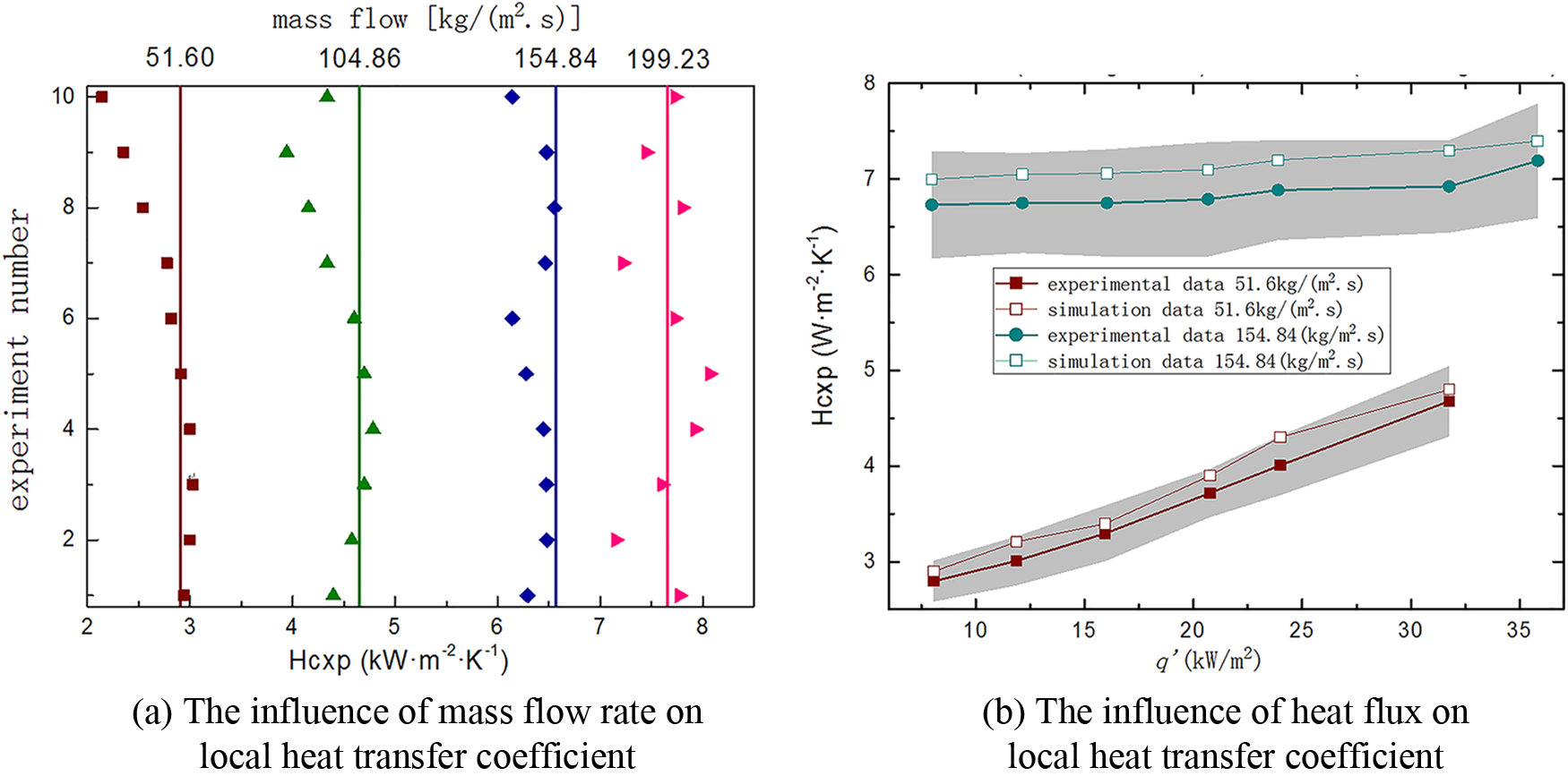
Figure 4: Validation of the numerical method
Fig. 4b shows the impact of heat flux changes on the local heat transfer coefficient under low mass flow rate (51.6 kg/(m2
Through comparative analysis, it is found that the numerical calculation results of this calculation model are basically in line with the trend of changes in the experimental research mentioned above. Therefore, the subsequent numerical calculations will use the above research methods and models.
The basic conditions of the numerical computation for the flow and heat exchange characteristics of the HCTT heat exchanger have been set. The structural parameters of the flow and heat transfer characteristics can be found by modifying the change of the cavity shape. The results of the study and the discussion will be introduced in the following part.
4.1 Effects of Initial Fluid Velocities on the Flow
As shown in Fig. 5, the change in the flow velocity of the internal and external flowing fluid in the helical tubes under different initial flow velocities can be seen. Fig. 5a shows the velocity change of the inner tube fluid in the helical tubes when the initial velocities are set as 1, 1.5, 2, 2.5, and 3 m/s. Fig. 5b shows the velocity change of the outer tube fluid in the helical tubes when the initial velocities are 1, 2, 3, 4 and 5 m/s. As shown in the figure, under the condition that the curvature of the current helical tube is unchanged, the curvature is not large enough to produce a fierce secondary flow. The fluid inside and outside the helical tubes is less affected by the secondary flow, and the flow velocity changes relatively smoothly. The fluid velocities change in the outer and the inner tubes, which are basically the same because of the shape of the helical tubes, but the values are different. It can be found that the velocity gradient of the internal and external fluids is small at low speeds, but when the initial velocity of the outer tube fluid increases, the velocity of the inner tube fluid also increases, and the velocity gradient between the two also gradually increases. This phenomenon is due to the secondary flow of the fluid acting as the velocity of the fluid in the spiral inner and outer tubes increases.
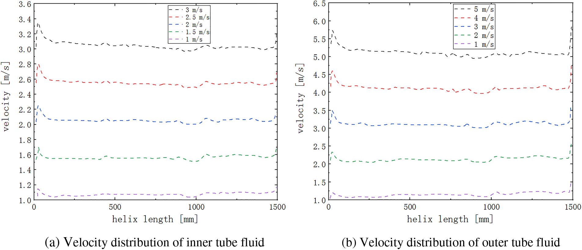
Figure 5: Velocity distribution inside the HCTT heat exchanger at different initial velocities
The fluid pressure distribution inside the HCTT heat exchanger can be seen in Fig. 6. The interval between pressures at different velocities continues to increase as the flow velocity increases under the condition that the flow velocity value interval is fixed, which satisfies the pressure and fluid flow calculation formula. At the outlet of the heat exchange tube, the distribution of the pressure field inside the HCTT heat exchanger changes approximately linearly along the winding direction of the helical tube. This is because, under the same overflow cross section, the flow rate has a linear relationship with the velocity after the initial velocity increases. There is no abrupt slope change in the pressure change curve, indicating that the resistance loss of the helical tubes to the fluid along the flow is evenly distributed, and there is no phenomenon that affects the flow process.
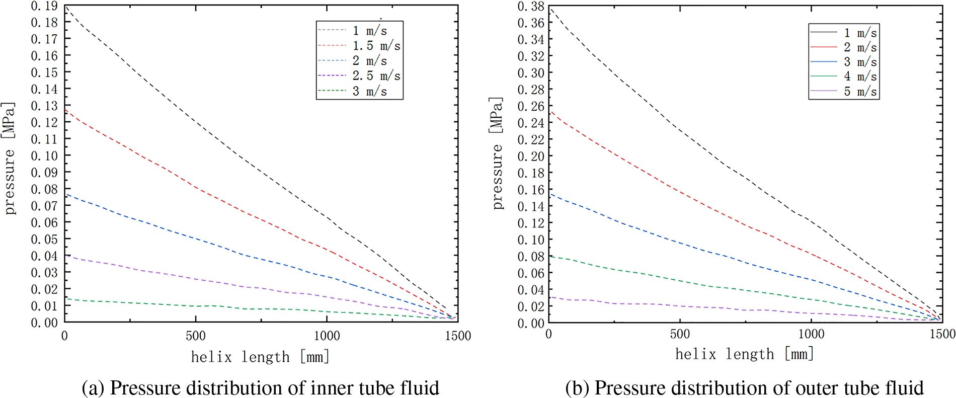
Figure 6: Pressure distribution inside the HCTT heat exchanger at different initial velocities
4.2 Effects of Middle Diameters on the Flow and Heat Transfer
As the most important geometric parameter controlling the radial direction of the helical tube, the influence of the pitch diameter D on the internal flow of the HCTT heat exchanger mainly focuses on the increase of the radial size of the helical tube, the increase of the time for the fluid flowing through the helical tube, and then more fluids contacts the wall of the helical tube. Therefore, the heat exchange process above improves the heat transfer performance of the helical tube.
Theoretically, to increase the length of the heat transfer channel will increase the heat exchange area, which will increase the amount of heat transfer between LNG and the ethylene glycol-water solution. The analytical results describing the dynamic characteristics of the flow field must be combined with the pressure loss distribution in the helical flow channel and the flow state. The internal pressure change curve of the helical tube under the two middle diameter sizes is shown in Fig. 7.
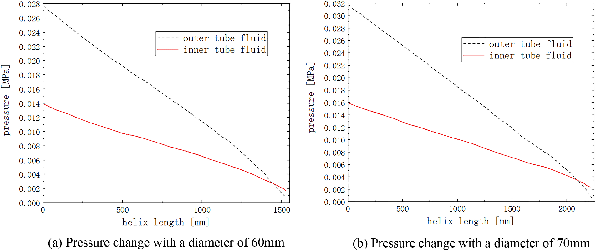
Figure 7: Pressure variation at different middle diameters
As shown in Fig. 7, as the middle diameter of the helical flow path inside the HCTT heat exchanger becomes larger, the pressure loss along the helical line gradually increases, and the trend of pressure change is also more stable. In addition, when the height of the entire helical flow channel in the vertical direction is unchanged, the radial dimension of the helical flow channel increases after increasing the middle diameter, so that the entire stroke of the helical flow channel also increases. For the tube, the change of the middle diameter mainly affects the change of the heat exchange stroke, which in turn impacts the heat exchange area. In the case of other conditions unchanged, the increase in the middle diameter increases the initial pressure. The main reason is that the increase in the flow stroke requires the helical tubes to have a greater initial pressure to overcome the greater loss along the path caused by the increase in flow stroke.
As shown in Fig. 8, with the increase of the middle diameter of the helical tube, the development trend of the fluid temperature in the helical tube does not change much. However, the overall length of the helical tube increases as the middle diameter becomes longer, so the increase in the middle diameter will decrease the gradient of temperature change under the same change trend and initial conditions.
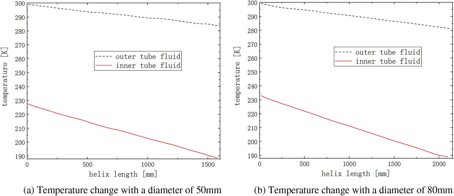
Figure 8: Temperature variation at different middle diameters
The main reason is that the increase in flow process reduces the average velocity of the fluid flow without increasing the inlet flow rate and pressure, and the heat transfer boundary layer near the tube wall is difficult to damage. As a result, the turbulent state is weakened, which reduces the heat transfer effect and slows the temperature change rate. It can be seen from the above that for the HCTT heat exchanger, the effect of increasing the surface heat transfer coefficient caused by changing the middle diameter cannot compensate for the loss of the heat exchange effect caused by the increased power consumption of fluid pumping.
The growth of the heat exchange stroke reduces the average velocity during the fluid flow. The heat transfer boundary layer near the tube wall is difficult to damage, which weakens the turbulent state, reduces the heat exchange efficiency and slows the temperature change rate. The main reason for this phenomenon is that the increase in flow process reduces the average velocity of the fluid flow without increasing the inlet flow rate and pressure, and the heat transfer boundary layer near the tube wall is difficult to damage. As a result, the turbulent state is weakened, which reduces the heat transfer effect and slows the temperature change rate. It can be seen from the above that for the HCTT heat exchanger, the effect of increasing the surface heat transfer coefficient caused by changing the middle diameter cannot compensate for the loss of heat transfer effect caused by the increased power consumption of fluid pumping.
4.3 Effects of the Middle Diameter Variation on Flow and Heat Transfer Characteristics
The middle diameter variation is to generate a helical line with a linear change in diameter. The characteristic of this form of helical tube is that the pitch of the helical flow channel changes in the axial direction, which in turn changes the initial state of the flow. The radial dimension gradually increases with increasing axial length. Compared with the HCTT heat exchanger of the same diameter, the flow rate should be the average value of the helical flow channels at both ends. The variable middle diameter of the HCTT heat exchanger is suitable for places where the installation position is limited to maximize the heat exchange capacity of the heat exchanger. The schematic diagram can be seen in Fig. 9.
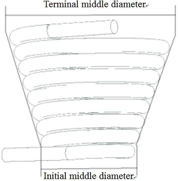
Figure 9: Schematic diagram of the HCTT heat exchanger with a change in the middle diameter
The structure of variable middle diameter is a helical tubes generated by linearly changing the diameter of the first and last ends. This structure has certain advantages in terms of installation requirements and compact structure. Therefore, in the following calculations, numerical simulation calculations will be carried out for this structure.
As shown in Fig. 10a, there is a graph showing the change of fluid pressure inside and outside the variable-diameter helical tubes with a middle terminal diameter of 70 mm and an initial middle diameter of 50 mm. When the size of the middle diameter changes linearly, the sections of the two ends of the helical flow channel are different. One side of the fluid gradually flows from the small and middle diameter to the large and middle diameter helical tubes, and one side of the fluid flows from the large and middle diameter to the small and middle diameter helical tubes. This process is mutual. The change in the middle diameter makes the middle diameter curvature of the initial section of the helical tubes larger, which makes the flow resistance slightly increase. However, compared with the helical tubes whose middle diameter is unchanged, the change of the middle diameter leads to a shorter overall process, the loss of pressure along the flow decreases, and the initial pressure increases under the condition of constant inlet flow rate, which is generally beneficial to the flow.
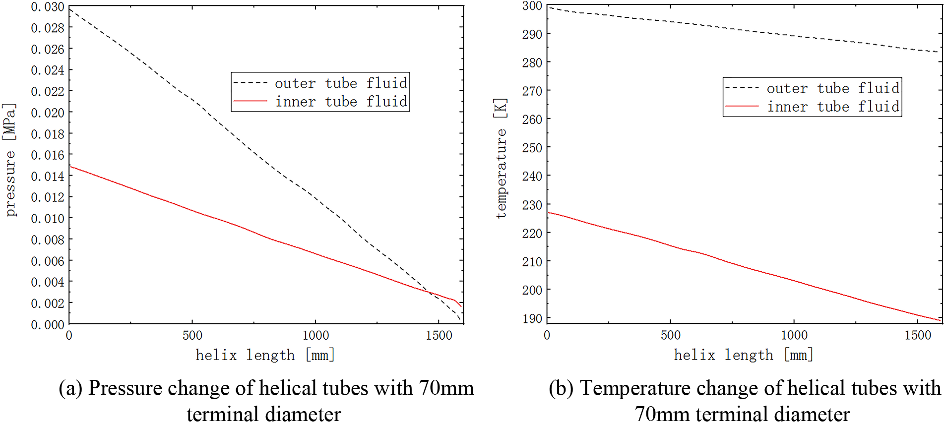
Figure 10: Pressure and temperature variation with a middle diameter of 70 mm
The main flow characteristics of helical tubes with variable diameters are not significantly different from helical tubes of the same diameter. In the area where the helical diameter changes, the flow area of the radial end of the flow gradually increases.
As shown in Fig. 10b, the overall flow trend has changed. For example, the length of the helical line increases after the middle diameter of the helical flow channel changes, which in turn causes the fluid to reach the same temperature change in different flow channel lengths. In addition, the maximum temperature of the inside fluid is reduced because the longer the helical tube, the larger the area of contact with the liquid LNG, and the cooling time will be reduced.
4.4 Effects of Helical Pitch on Flow and Heat Transfer
From Fig. 11, the increase of the helical pitch greatly influences the pressure gradient change in the helical flow channel. Firstly, the increase in the pitch makes the flow channel excessively smoother, the secondary flow generated by the impact on the wall surface during the fluid flow is weakened, and the maximum pressure values of the fluid on both the inside and outside are increased due to the increase in pitch. Secondly, there is no significant change in the trend of the pressure gradient. This is because the helical flow channel has a low pressure loss. However, there will still be a certain local resistance loss in the helical area. When the number of helical turns is reduced, the pressure loss of the entire helical flow channel will be reduced.
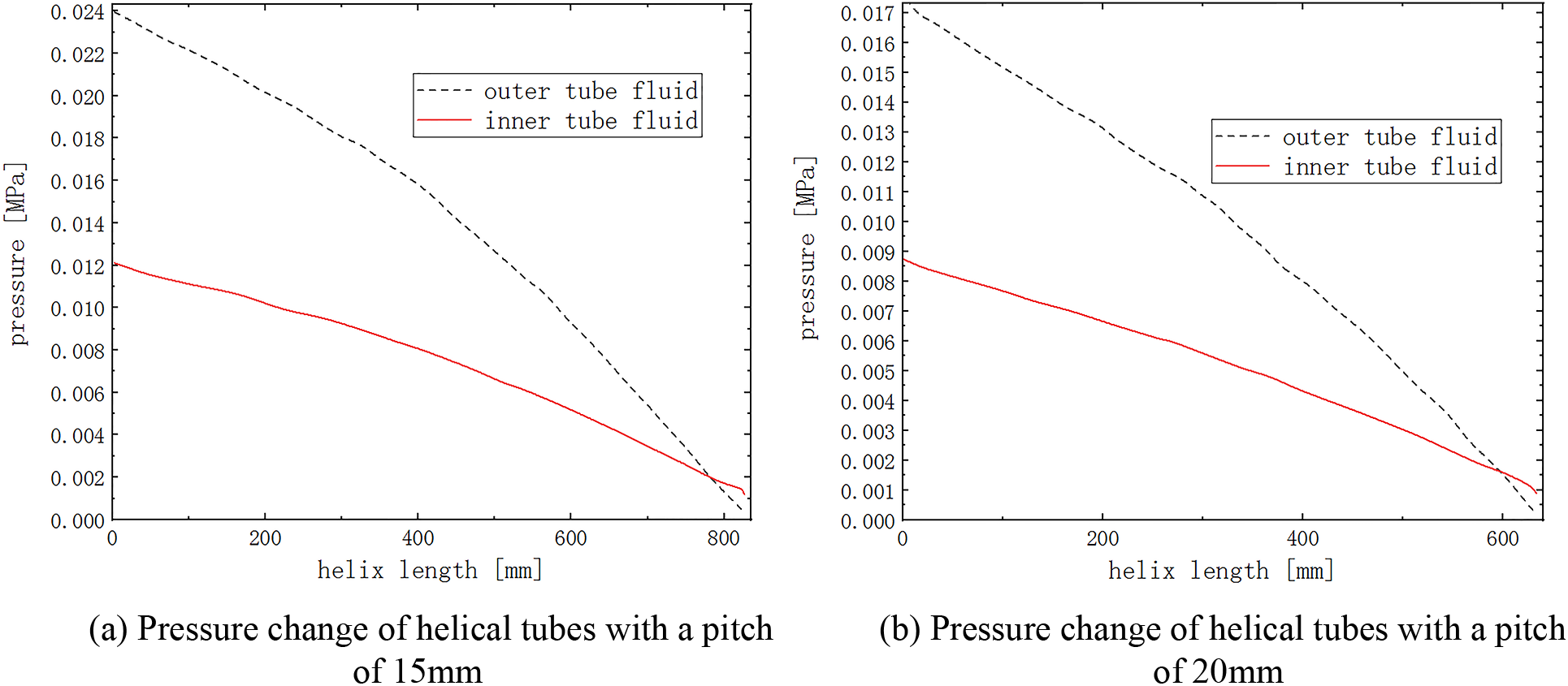
Figure 11: Pressure variation with different pitch
As shown in Fig. 12, the number of turns of the helical tube decreases after the pitch is increased from 15 to 20 mm. The wall area of the heat exchange with the inner fluid is reduced, but the helical flow channel is shortened, and the outer fluid reaches the helical flow channel terminal faster. Therefore, the minimum temperature of the fluid in the helical flow channel has decreased, and the heat transfer coefficient has increased. The effect of the helical pitch on the flow is mainly due to the increase in the axial dimension of the helix, the time for the fluid to flow through the helical flow channel is increased, and more liquid is in contact with the wall surface of the helical flow channel. A bigger pitch means the lower resistance that can also improve the flow. The increased pitch reduces the fluid contact area between the inner tube and the outer tube. However, the increase of the helical pitch reduces the excessive length of each turn of the helical tube, and the curvature of the excessive part increases. The effect of turbulence caused by the increased curvature is enhanced, and the heat exchange effect can also be improved. In addition, the improvement of the flow state also enhances the heat transfer effect, so the appropriate increase of the pitch can improve the heat transfer performance of the helical flow channel.
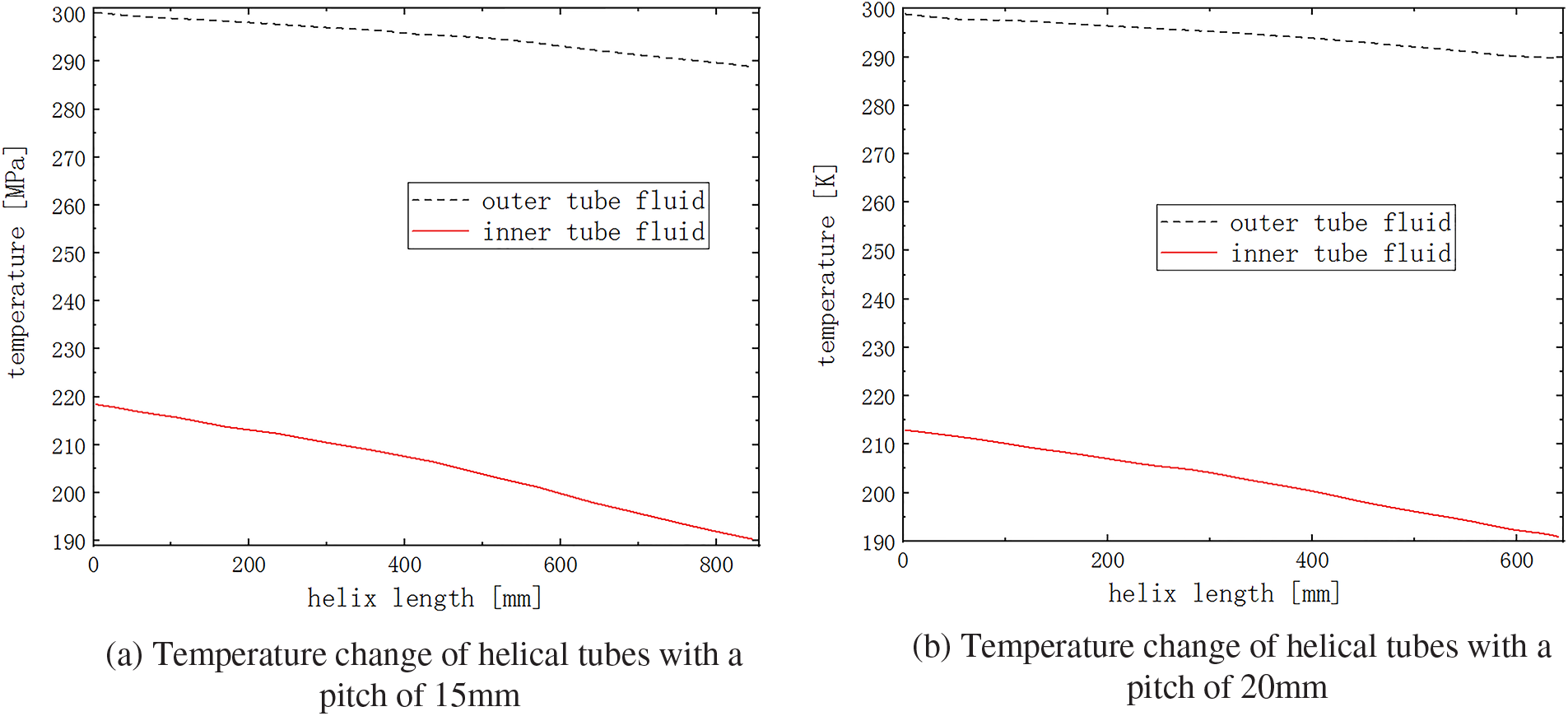
Figure 12: Fluid temperature change with different pitch
The CFD simulations of the HCTT heat exchanger are carried out by changing the helical diameters and helical pitch parameters under different initial conditions. The main conclusions are summarized as follows:
When the initial velocity of the outer tube fluid increases, the velocity of the inner tube fluid also increases, and the velocity gradient between the two gradually increases. The resistance loss of the helical tube to the fluid is evenly distributed during the flow of fluids with different initial velocities. The distribution of the pressure field inside the helical tube is approximately linearly along the winding direction of the helix.
When the middle diameter of the helical tube becomes larger, the pressure loss along the helix gradually increases, and the trend of pressure change is also more stable. For the helix tube, the change of the middle diameter mainly affects the change of the heat exchange stroke and has an influence on the heat exchange area.
For the HCTT heat exchanger, the effect of increasing the surface heat transfer coefficient caused by changing the middle diameter cannot compensate for the loss of heat exchange efficiency caused by the increased power consumption of the fluid pumping power. The change of the middle diameter causes the overall process to become shorter, the pressure loss along the flow decreases, and the initial pressure rises under the condition of constant inlet flow rate, which is generally beneficial to the flow.
The change in the middle diameter reduces the curvature of the helical tube, which promotes the occurrence of secondary flow. The fluid flow in the axial direction promotes the destruction of the heat transfer boundary layer, to a certain extent, increases the intensity of the turbulent flow to make the fluid velocity distribution and temperature distribution uniform.
The increased pitch reduces the fluid contact area between the inner and outer tubes. However, the increase of the helical pitch reduces the excessive length of each turn of the helical tube, and the curvature of the excessive part increases. The effect of turbulence caused by the increased curvature is enhanced, and the heat transfer effect is improved. The appropriate increase in the pitch improves the heat transfer performance of the helical flow channel.
Acknowledgement: We would like to express our heartfelt gratitude to Professor Xu Boyan who point out the research direction of this study.
Funding Statement: This work was supported by Innovative Team Introduction Projects for New Universities in Jinan City (No. 2021GXRC075).
Author Contributions: Fayi Yan conducted theoretical derivation, numerical simulation and result analysis; Xuejian Pei established the numerical calculation model; He Lu carried out a part of numerical simulation; Shuzhen Zong compiled the calculation results.
Availability of Data and Materials: Most of the data generated or analysed during this study are included in this published article. Other data is available from corresponding author, please contact yanfayi@sdjzu.edu.cn.
Conflicts of Interest: The authors declare that they have no conflicts of interest to report regarding the present study.
References
1. Qiu, C. X., Chen, S. H., Shen, Y. W., Tao, X., Gan, Z. H. (2023). Numerical and experimental study on a tube-in-tube heat exchanger working at liquid-hydrogen temperature with a large temperature span. International Journal of Heat and Mass Transfer, 208, 124089. [Google Scholar]
2. Gu, X., Zheng, Z., Xiong, X., Jiang, E. H. (2022). Heat transfer and flow resistance characteristics of helical baffle heat exchangers with twisted oval tube. Journal of Thermal Science, 31, 370–378. [Google Scholar]
3. Tang, S. Z., Li, H. W., Zhou, J. J. (2021). Parametric investigation and correlation development for thermal-hydraulic characteristics of honeycomb 4H-type finned tube heat exchangers. Applied Thermal Science, 199, 117542. [Google Scholar]
4. Marzouk, S. A., Abou Al-Sood, M. M., El-Said, E. M. S. (2023). Experimental and numerical investigation of a novel fractal tube configuration in helically tube heat exchanger. International Journal of Thermal Sciences, 187, 108175. [Google Scholar]
5. Elattar, H. F., Fouda, A., Nada, S. A., Refaey, H. A., Al-Zahrani, A. (2018). Thermal and hydraulic numerical study for a novel multi tubes in tube helically coiled heat exchangers: Effects of operating/geometric parameters. International Journal of Thermal Science, 128, 70–83. [Google Scholar]
6. Liu, S. B., Huang, W. X., Bao, Z. W., Zeng, T., Qiao, M. et al. (2021). Analysis, prediction and multi-objective optimization of helically coiled tube-in-tube heat exchanger with double cooling source using RSM. International Journal of Thermal Sciences, 159, 106568. [Google Scholar]
7. Liu, P. H., Wang, R. T., Liu, S. B., Bao, Z. W. (2023). Experimental study on the thermal-hydraulic performance of a tube-in-tube helical coil air-fuel heat exchanger for an aero-engine. Energy, 267, 126626. [Google Scholar]
8. Cao, Y., Abdous, M. A., Ghazanfari Holagh, S., Bao, Z. W. (2021). Entropy generation and sensitivity analysis of R134a flow condensation inside a helically coiled tube-in-tube heat exchanger. International Journal of Refrigeration, 130, 104–116. [Google Scholar]
9. Wang, W., Zhang, Y., Lee, K., Li, B. (2019). Optimal design of a double pipe heat exchanger based on the outward helically corrugated tube. International Journal of Heat and Mass Transfer, 135, 706–716. [Google Scholar]
10. Verma, T. N., Nashine, P., Singh, D. V., Singh, T. S., Panwar, D. (2017). ANN: Prediction of an experimental heat transfer analysis of concentric tube heat exchanger with corrugated inner tubes. Applied Thermal Engineering, 120, 219–227. [Google Scholar]
11. Zhang, C., Wang, D., Xiang, S., Han, Y., Peng, X. (2017). Numerical investigation of heat transfer and pressure drop in helically coiled tube with spherical corrugation. International Journal of Heat and Mass Transfer, 113, 332–341. [Google Scholar]
12. Fouda, A., Nada, S. A., Elattar, H. F., Refaey, H. A., Bin-Mahfouz, A. S. (2018). Thermal performance modeling of turbulent flow in multi tube in tube helically coiled heat exchangers. International Journal of Mechanical Sciences, 135, 621–638. [Google Scholar]
13. Huang, L., Aute, V., Radermacher, R. (2014). A finite volume coaxial heat exchanger model with moving boundaries and modifications to correlations for two-phase flow in fluted annuli. International Journal of Refrigeration, 40, 11–23. [Google Scholar]
14. Wang, G. H., Dbouk, T., Wang, D. B., Pei, Y. S., Peng, X. et al. (2020). Experimental and numerical investigation on hydraulic and thermal performance in the tube-side of helically coiled-twisted trilobal tube heat exchanger. International Journal of Thermal Sciences, 153, 106328. [Google Scholar]
15. Mahdi, M. S., Mahood, H. B., Mahdi, J. M., Khadom, A. A., Campbell, A. N. (2020). Improved PCM melting in a thermal energy storage system of double-pipe helical-coil tube. Energy Conversion and Management, 203, 112238. [Google Scholar]
16. Ndiaye, D. (2017). Transient model of a refrigerant-to-water helically coiled tube-in-tube heat exchanger with corrugated inner tube. Applied Thermal Engineering, 112, 413–423. [Google Scholar]
17. Abu-Hamdeh, N. H., Bantan, R. A. R., Tlili, I. (2020). Analysis of the thermal and hydraulic performance of the sector-by-sector helically coiled tube heat exchangers as a new type of heat exchangers. International Journal of Thermal Science, 50, 106229. [Google Scholar]
18. Zhang, X. Y., Zhao, M., Liu, L., Huan, C., Zhao, Y. J. et al. (2020). Numerical simulation on heat storage performance of backfill body based on tube-in-tube heat exchanger. Construction and Building Materials, 265, 120340. [Google Scholar]
19. Fsadni, A. M., Whitty, J. P. M. (2016). A review on the two-phase pressure drop characteristics in helically coiled tubes. Applied Thermal Engineering, 103, 616–638. [Google Scholar]
20. Solanki, A. K., Kumar, R. (2019). Two-phase flow condensation heat transfer characteristic of R-600a inside the horizontal smooth and dimpled helical coiled tube in shell type heat exchanger. International Journal of Refrigeration, 107, 155–164. [Google Scholar]
21. Dubba, S. K., Kumar, R. (2018). Experimental investigation on flow of R-600a inside a diabatic helically coiled capillary tube: Concentric configuration. International Journal of Refrigeration, 86, 186–195. [Google Scholar]
22. Wongwises, S., Polsongkram, M. (2006). Condensation heat transfer and pressure drop of HFC-134a in a helically coiled concentric tube-in-tube heat exchanger. International Journal of Heat and Mass Transfer, 49, 4386–4398. [Google Scholar]
23. Zhao, B. J., Zhang, T., Tan, J., Zhao, Y. J., Xue, R. J. et al. (2022). Design and optimization of the four-stage recuperative coiled tube-in-tube heat exchanger for a 1.8 K hybrid cryocooler. Cryogenics, 126, 103535. [Google Scholar]
24. Mukesh Kumar, P. C., Chandrasekar, M. (2020). A review on helically coiled tube heat exchanger using nanofluids. Materials Today: Proceedings, 21, 137–141. [Google Scholar]
25. Huminic, G., Huminic, A. (2016). Heat transfer and entropy generation analyses of nanofluids in helically coiled tube-in-tube heat exchangers. International Communication in Heat and Mass Transfer, 71, 118–125. [Google Scholar]
26. Zhou, C., Ni, L., Ke, Y., Yao, Y. (2019). Experimental study on the thermal performance of multi-row helically coiled tube heat exchanger for surface water-source heat pump. Applied Thermal Engineering, 149, 1274–1286. [Google Scholar]
27. Kumar, P. G., Thangapandian, N., Vigneswaran, V. S., Vinothkumar, S. (2022). Heat transfer, pressure drop, and exergy analyses of a shot-peened tube in the tube heat exchanger using Al2O3 nanofluids for solar thermal applications. Powder Technology, 401, 117299. [Google Scholar]
28. Zhao, Q., Liu, F., Liu, C., Tian, M., Chen, B. (2017). Influence of helical pitch on the thermal behaviors of energy piles with helical-tube heat exchanger. Applied Thermal Engineering, 125, 1280–1290. [Google Scholar]
29. Mashoofi, N., Pesteei, S. M., Moosavi, A., SadighiDizaji, H. (2017). Fabrication method and thermal-frictional behavior of a tube-in-tube helically coiled heat exchanger which contains turbulator. Applied Thermal Engineering, 111, 1008–1015. [Google Scholar]
30. Damle, R. M., Ardhapurkar, P. M., Atrey, M. D. (2015). Numerical analysis of the two-phase heat transfer in the heat exchanger of a mixed refrigerant Joule-Thomson cryocooler. Cryogenics, 72, 103–110. [Google Scholar]
31. Ardhapurkar, P. M., Sridharan, A., Atrey, M. D. (2014). Experimental investigation on temperature profile and pressure drop in two-phase heat exchanger for mixed refrigerant Joule-Thomson cryocooler. Applied Thermal Engineering, 66, 94–103. [Google Scholar]
32. Chen, D. S., Shi, M. Y. (2014). Flow boiling heat transfer of LNG in vertical smooth tube at 0.5 MPa. CIESC Journal, 65(4), 1199–1207. [Google Scholar]
Cite This Article
 Copyright © 2024 The Author(s). Published by Tech Science Press.
This work is licensed under a Creative Commons Attribution 4.0 International License , which permits unrestricted use, distribution, and reproduction in any medium, provided the original work is properly cited.
 Downloads
 Citation Tools