
 Submit a Paper
 Propose a Special lssue
 Open Access
ARTICLE

Flow Patterns and Heat Transfer Characteristics of a Polymer Pulsating Heat Pipe Filled with Hydrofluoroether
1 Department of Mechanical and Mathematical Engineering, Graduate School of Science and Technology, Kumamoto University, Kumamoto, 860-8555, Japan
2 Division of Industrial Fundamentals, Faculty of Advanced Science and Technology, Kumamoto University, Kumamoto, 860-8555, Japan
* Corresponding Author: Yasushi Koito. Email:
Frontiers in Heat and Mass Transfer 2024, 22(1), 49-63. https://doi.org/10.32604/fhmt.2024.047502
Received 07 November 2023; Accepted 26 December 2023; Issue published 21 March 2024
 View Full Text
 Download PDF
Abstract
Visualization experiments were conducted to clarify the operational characteristics of a polymer pulsating heat pipe (PHP). Hydrofluoroether (HFE)-7100 was used as a working fluid, and its filling ratio was 50% of the entire PHP channel. A semi-transparent PHP was fabricated using a transparent polycarbonate sheet and a plastic 3D printer, and the movements of liquid slugs and vapor plugs of the working fluid were captured with a high-speed camera. The video images were then analyzed to obtain the flow patterns in the PHP. The heat transfer characteristics of the PHP were discussed based on the flow patterns and temperature distributions obtained with thermocouples. Before starting heating, because of high wettability, large liquid slugs positioned at the evaporator section of the PHP. After starting heating, since the occurrence of boiling divided the large liquid slugs, oscillatory flow of smaller liquid slugs and vapor plugs was found in the PHP. Clear circulation flow of liquid slugs and vapor plugs was observed when the power input to the PHP was larger than 12.0 W. The flow patterns and temperature distributions confirmed that the circulation flow enhanced the heat transfer from the evaporator section to the condenser section of the PHP. In the circulation flow mode, large growth and contraction of vapor plugs were found one after another in all even-numbered PHP channels. However, the analysis of flow patterns clarified that the phase-change heat transfer rate by large growth and contraction of vapor plugs was 19% of the total heat transfer rate of the PHP. Although the generation of large vapor plugs was found in the PHP, most of the heat was transferred by the sensible heat of the working fluid.Keywords
Nomenclature
| A | Cross-sectional area (m2) |
| Bo | Bond number (−) |
| c | Specific heat (J/(kgK)) |
| D | Diameter (m) |
| g | Gravitational acceleration (m/s2) |
| hfg | Latent heat (J/kg) |
| L | Length (mm, m) |
| Mass flow rate (kg/s) | |
| P | Electric power (W) |
| Q | Heat transfer rate (W) |
| R | Thermal resistance (K/W) |
| s | Standard deviation (°C) |
| T | Temperature (°C) |
| t | Time (s, min) |
| v | Growth rate (m/s) |
| y | Distance (mm) |
| Greek Symbols | |
| η | Ratio defined by Eq. (6) |
| ρ | Density (kg/m3) |
| σ | Surface tension (N/m) |
| Superscript | |
| i | i-th |
| N | N-th |
| Subscripts | |
| 1, 2 | Position |
| A | Point (A) |
| a | Adiabatic section |
| ave | Average |
| B | Point (B) |
| C | Point (C) |
| c | Condenser section |
| e | Evaporator section, Evaporation |
| in | Inlet |
| l | Liquid |
| out | Outlet |
| p | Phase change |
| PHP | Pulsating heat pipe |
| v | Vapor |
| w | Cooling water |
Pulsating heat pipes (PHPs) are a two-phase thermal device that transports heat from one position to another. Like conventional capillary-driven heat pipes [1–5], the PHP is a passive thermal device with no external power input. The PHP was invented by Akachi [6] in 1990, and, unlike capillary-driven heat pipes, is made of a serpentine channel consisting of multiple parallel channels without any capillary-wick structure. An appropriate amount of working fluid is enclosed in the serpentine channel, and it distributes in the form of liquid slugs and vapor plugs. When one end of the PHP is heated while the other end is cooled, oscillatory flow of the liquid slugs and vapor plugs is induced, which transports heat from the heated (evaporator) section to the cooled (condenser) section. Review articles regarding the PHPs were presented by Han et al. [7–10].
Since the oscillatory flow is a unique feature of the PHP, many visualization experiments have been conducted to investigate the flow characteristics of a working fluid in the PHP. Recently, Ling et al. [11] investigated the flow regimes of a three-dimensional copper PHP filled with methanol as a working fluid. The visualization was conducted by replacing one of the copper elbows with a glass one, and three different flow regimes were identified during the PHP operation. Zhang et al. [12] conducted a visualization experiment for a PHP with silica nanofluid. They used the PHP made of quartz glass and SiO2-H2O nanofluid with different concentrations. Yasuda et al. [13] visualized the behaviors of a working fluid in a flat-plate PHP made of aluminum alloy. The working fluid was R1336mzz(Z), and the neutron radiography was employed for visualization. Iwata et al. [14] visualized the local heat flux distribution of a micro-PHP charged with HFC-134a as a working fluid. The local heat fluxes between the working fluid and the PHP wall were estimated by solving the inverse heat conduction problem with temperature maps as input data. Xu et al. [15] presented a visualization-based experimental study of a gravity PHP. An electrical coolant was used as a working fluid. The heat transfer characteristics and flow pattern changes of the PHP were investigated under different heat inputs. Li et al. [16] developed an experimental setup for the visualization study of a nitrogen PHP. The PHP was fabricated using MEMS technology with silicon base plate and BF33 glass cover plate. Flow images of the nitrogen PHP were obtained for the first time.
Most of the previous PHP studies have focused on metal PHPs [17–22]. However, in recent years, polymer PHPs have also been studied for their advantages over metal PHPs, that is, low cost, light weight, easy processability, mechanical flexibility, acid resistance, and dielectric property. Lin et al. [23] used polydimethylsiloxane for the fabrication of a PHP. The fabrication process of the PHP was shown, and heat transfer experiments were conducted using methanol and ethanol as working fluids. Lim et al. [24] developed a polymer-based flexible PHP, which consisted of a multilayer laminated film and a low-density polyethylene sheet. Hydrofluoroether (HFE)-7000 was used as a working fluid. A series of experiments was conducted to evaluate the thermal performance and long-term reliability of the PHP. Hao et al. [25] fabricated a PHP with polytetrafluoroethylene, and conducted experiments to investigate the startup mechanism, temperature oscillation, liquid slug oscillation, and heat transfer performance of the PHP. Water, ethanol, and acetone were used as working fluids. Koito et al. [26] presented an additively manufactured polymer PHP. A serpentine channel was 3D-printed directly onto a thin polycarbonate sheet. Acrylonitrile butadiene styrene was used as 3D printing material, and HFE-7100 was employed as a working fluid. Alqahtani et al. [27] conducted experiments for a flexible flat PHP made of polypropylene. Using ethanol and FC-72 as working fluids, the thermal performance of the PHP was investigated at four different bending angles.
The number of publications for polymer PHPs is much smaller than that for metal PHPs. Because of this, sufficient discussion has not been made regarding the flow patterns and heat transfer characteristics in polymer PHPs. Applicability of the results of metal PHPs to polymer PHPs is not clear. The understanding of the thermal and hydrodynamic characteristics is important for further improvement of polymer PHPs. In the authors’ group, the experimental studies were conducted on the heat transfer characteristics of polymer PHPs [26,28]; however, a series of flow patterns in polymer PHPs have not been obtained except for one flow pattern captured in the preliminary experiment [29]. In the present study, therefore, visualization experiments were conducted with a semi-transparent polymer PHP. Based on the previous experiments [26,28,29], HFE-7100 was used as a working fluid. Movements of liquid slugs and vapor plugs of the working fluid in the PHP were captured by using a high-speed camera, and their flow patterns were obtained by conducting video analysis. Temperature distributions of the PHP were simultaneously obtained with thermocouples. The heat transfer characteristics of the PHP were discussed with flow patterns.
2 Details of the Semi-Transparent Polymer PHP
As shown in Fig. 1, a semi-transparent PHP was fabricated by bonding a transparent polymer sheet onto a serpentine channel body. The transparent polymer sheet was a 0.25-mm-thick polycarbonate (PC) sheet, through which the flow patterns in the PHP were captured. Fig. 2 shows the schematic diagram of the serpentine channel body. The design and fabrication method of the serpentine channel body were the same as those in the previous paper [26]. Since the details of the serpentine channel body were already presented in that paper, only the main points are described here. Fourteen 150-mm-long parallel channels were designed with a cross section of 1.3 mm wide and 1.1 mm high, and the ends of each channel were connected to form a closed serpentine channel. As shown in the figure, each channel is numbered Ch. 1, Ch. 2, ..., Ch. 14. The serpentine channel body was obtained by additively manufacturing walls between channels onto a 0.12-mm-thick PC sheet. A plastic 3D printer was employed with acrylonitrile butadiene styrene (ABS) filament as 3D printing material. The 0.25-mm-thick PC sheet was thermally bonded onto the serpentine channel body. The outer surface of the PHP was chemically treated to maintain airtightness.

Figure 1: Schematic diagram of the semi-transparent PHP
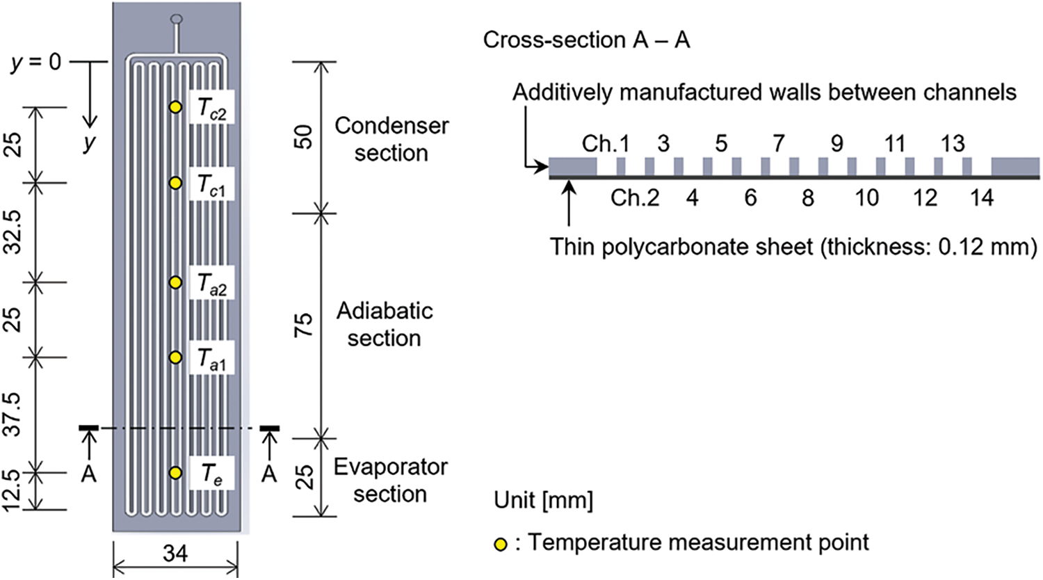
Figure 2: Schematic diagram of the serpentine channel body
3.1 Experimental Apparatus and Procedure
As shown in Fig. 3, a high-speed camera and lighting devices were installed in the experimental apparatus that was used in the previous study [26]. The PHP was placed vertically. A heater and a cooling jacket were attached to the PHP with thermal grease on the 0.12-mm-thick PC sheet side. The heater was located at the bottom of the PHP and was connected to a power supply. The cooling jacket was mounted on the top of the PHP and was piped to a thermostatic bath through a flow meter and an overflow tank. As shown in Fig. 2, the evaporator, adiabatic, and condenser sections of the PHP were 25, 75, and 50 mm long, respectively. A high-speed camera was installed with lighting devices to capture the flow patterns in the PHP through the 0.25-mm-thick PC sheet. Except for the heated and cooled sections, the rest of the PHP was covered with thermal insulation material to reduce heat loss from the PHP to ambient air. The thermal insulation material on the 0.25-mm-thick PC sheet side was removed temporarily during video shooting. Temperature measurement points are also shown in Figs. 2 and 3. T-type thermocouples were attached on the surface of the 0.12-mm-thich PC sheet at the evaporator (Te), adiabatic (Ta1, Ta2), and condenser (Tc1, Tc2) sections. In addition, the thermocouples were also set at the inlet (Tw,in) and outlet (Tw,out) of the cooling jacket to evaluate the heat transfer rate of the PHP (QPHP) by the following equation:
where

Figure 3: Picture and schematic diagram of the experimental apparatus
The PHP was filled with HFE-7100 as the working fluid. The filling ratio of the working fluid was 50% of the total volume of the serpentine channel. The experiment was started by supplying cooling water from the thermostatic bath to the cooling jacket at around 50 g/min. Tw,in was kept at around 5.0°C throughout the experiment. Then, the PHP was heated with the heater at 4.0 W of electric power (P), and temporal changes in Te, Ta1, Ta2, Tc1, Tc2, and Tw,out were obtained. When the temperature changes reached a pseudo steady state, the flow patterns in the PHP were captured with the high-speed camera. The flame rate was 1000 fps, and the resolution was 300 × 1024 pixels. P was increased stepwise from 4.0 to 19.0 W in 1.0 W intervals, and the video shooting at pseudo steady state was repeated at every P. According to the guide to the expression of uncertainty in measurement [30], the uncertainties for T,
Fig. 4a shows the image of liquid slugs and vapor plugs in the PHP. This image was obtained at P = 5.0 W with the high-speed camera. A part of Ch. 7 is enlarged, where the width is increased by five times. Liquid slugs and vapor plugs can be recognized by a difference in luminance. Dark blocks imply vapor plugs while liquid slugs are shown in light color. By analyzing the video using a video analysis software, the flow pattern of liquid slugs and vapor plugs was obtained as shown in Fig. 4b. The abscissa is the time (t), and the ordinate is the distance (y) along the serpentine channel. y = 0 mm is located at the top of Ch. 1 as shown in Fig. 2. The state in Fig. 4a was set to t = 0 s, and the movements of liquid slugs and vapor plugs in the enlarged channel for t ≥ 0 s are shown in Fig. 4b. Since clear flow patterns can be obtained by the present video analysis, the flow patterns were obtained at every P.

Figure 4: Image and flow pattern of liquid slugs and vapor plugs in the PHP (Ch. 7, P = 5.0 W)
4.1 Transient Variation in Temperatures
Fig. 5 shows the temporal changes in the temperatures at the evaporator (Te), adiabatic (Ta1, Ta2), and condenser (Tc1, Tc2) sections. The abscissa is the time (t) from the start of heating. The electric power (P) to the heater is shown in the figure and was increased stepwise from 4.0 to 19.0 W in 1.0 W intervals. The QPHP value evaluated by Eq. (1) is also shown in the figure, and was 14.9% smaller than P because of heat loss. The 14.9% was obtained at P = 19.0 W because the percentage of the uncertainty in QPHP was smallest. Te began to rise immediately after starting heating at P = 4.0 W, and the oscillatory flow of liquid slugs and vapor plugs started when Te was 54°C. After a while, the temperature changes reached pseudo steady state, and then P was increased to 5.0 W. The increase in P with 1.0 W intervals was continued until P = 19.0 W, and the temperature distributions at pseudo steady state were obtained at every P. Since some fluctuations were found in the temperatures, their standard deviations (s) were calculated at pseudo steady state, and the relation between s and P is shown in Fig. 6. Because the fluctuations of Tc1 and Tc2 were small, the s values of Te, Ta1, and Ta2 are shown in this figure. Compared with Te and Ta2, a large fluctuation was found in Ta1 when P was 4.0–12.0 W, which implies that heated liquid slugs and cooled ones were frequently replaced in the PHP channel near the measurement point of Ta1. It was also found that the fluctuations of Te, Ta1, and Ta2 became much smaller when P was larger than 12.0 W, which would be affected by the flow pattern of liquid slugs and vapor plugs in the PHP. More discussion on the flow patterns is made in Section 4.3.

Figure 5: Transient variations in temperatures of the PHP

Figure 6: Standard deviations in temperatures at pseudo steady state
The thermal resistance (R) of the PHP was evaluated by the following equation:
where Tc,ave is the average of Tc1 and Tc2. Fig. 7 compares the R value at pseudo steady state for the present PHP with that for the previous one [26]. The serpentine channel body of the previous PHP was the same as that of the present one, but the previous PHP was obtained by additively manufacturing a polymer wall on the serpentine channel body. A 3D printer was used with ABS filament as 3D printing material. The polymer wall thickness was 0.9 mm. Instead of the additively manufactured polymer wall, a transparent PC sheet was used in the present PHP. As shown in Fig. 7, although a small difference was found at small P, close agreement was obtained between the R values of the present and previous PHPs. This agreement implies that the replacement of the additively manufactured polymer wall with the transparent PC sheet hardly affected the heat transfer characteristics of the PHP.

Figure 7: Thermal resistances of the PHPs at pseudo steady state
4.2 Initial Distribution of Working Fluid
Fig. 8 shows the initial distribution of liquid slugs and vapor plugs in all the channels (Ch. 1–Ch. 14) before starting heating. Since liquid slugs and vapor plugs remained stationary, the flow pattern during only one second is shown. The evaporator, adiabatic, and condenser sections are indicated on the side of flow pattern with channel number. It was found that the evaporator and adiabatic sections were almost light in color while the condenser section was mostly dark. This pattern implies that large liquid slugs positioned at the evaporator section while large vapor plugs stayed at the condenser section. Even if small liquid slugs and small vapor plugs were generated and mixed in the PHP channel by applying a vibration to the PHP, the liquid slugs flowed down and merged at the evaporator section when the PHP was placed vertically. At the same time, the vapor plugs flowed up and merged at the condenser section resulting in a separation of the working fluid in the PHP channel. It is known that distinct liquid slugs and vapor plugs can form in a capillary tube without being affected by the gravitational force when the Bond number (Bo) is less than 4 [31]. The Bond number is defined by
where g is the gravitational acceleration, ρl is the liquid density, ρv is the vapor density, D is the diameter of a capillary tube, and σ is the surface tension. The Bo value of the present PHP was 1.5, which was obtained by using the hydraulic diameter of the PHP channel. Fig. 8 implies that, although Bo was less than 4, the distribution of liquid slugs and vapor plugs in the present PHP was greatly affected by the gravitational force. The contact angle of an HFE-7100 droplet on an 3D-printed ABS wall is almost zero. This high wettability caused the above-mentioned flow down of liquid slugs when the PHP was placed vertically [29]. Fig. 8 also shows that although the evaporator section was occupied by large liquid slugs, thin dark lines that imply small vapor plugs were found in the evaporator section. When the PHP was started heating, evaporation occurred at the vapor-liquid interface between the small vapor plugs and large liquid slugs, and thus boiling was observed in the evaporator section. Since the boiling divides the large liquid slugs into smaller ones, the oscillatory flow of smaller liquid slugs was found in the PHP.

Figure 8: Initial distribution of liquid slugs and vapor plugs in all the channels
Fig. 9 shows the flow patterns in Ch. 9–Ch. 14 when P was (a) 5.0 W, (b) 8.0 W, and (c) 12.0 W. The evaporator, adiabatic, and condenser sections are indicated on the side of each flow pattern with channel number. Besides, in each flow pattern, three vapor-liquid interfaces are emphasized by orange lines for better understanding of their movements. At P = 5.0 W in Fig. 9a, although the oscillation of liquid slugs and vapor plugs occurred in the PHP channel, the oscillation sometimes stopped and restarted. Because of this, this flow pattern had non-oscillating states, which are indicated by arrows in the figure. The weak oscillation of liquid slugs and vapor plugs was the reason for large R at low P in Fig. 7. When P was increased to 8.0 W in Fig. 9b, the stop of oscillation became less frequent, and thus the number of non-oscillating state became smaller. Moreover, the orange lines in Fig. 9b show that the center position of oscillation moved in y direction within the time from t = 0 s to t = 5.0 s. This flow pattern implies a circulation flow, in which liquid slugs and vapor plugs are flowing in one direction with oscillation. The circulation flow was clearly found at P = 12.0 W in Fig. 9c. As shown in Fig. 6, the fluctuations of Te, Ta1, and Ta2 became much smaller when P was larger than 12.0 W. This is because of the occurrence of circulation flow. Moreover, smaller values of R at high P in Fig. 7 confirmed that the circulation flow enhanced the heat transfer from the evaporator section to the condenser section of the PHP.

Figure 9: Flow patterns in Ch. 9–Ch. 14 at P = 5.0, 8.0, and 12.0 W
Fig. 10a shows the flow pattern in Ch. 13 and Ch. 14 when P was 16.0 W. The circulation flow was clearly confirmed at this heat input; liquid slugs and vapor plugs were flowing in one direction from Ch. 13 to Ch. 14. In addition, Ch. 13 was mostly liquid slugs while large growth and contraction of vapor plugs were found one after another in Ch. 14. Regarding three large vapor plugs termed VP-1, VP-2, and VP-3 in the figure, front and rear vapor-liquid interfaces were tracked by orange and light blue lines, respectively. By using Point (A)–Point (D) indicated in the figure, the growth and contraction processes of each vapor plug are roughly explained as follows. The tracking was stared at Point (A), where a vapor plus was small in Ch. 13, and its front vapor-liquid interface entered the evaporator section. Immediately after that, the small vapor plug grew rapidly to form a large vapor plug in Ch. 14. The large vapor plug started condensing at Point (B), where the front vapor-liquid interface reached the condenser section. The evaporation ended when the rear vapor-liquid interface left from the evaporator section at Point (C). During the period from Point (B) to Point (C), the vapor plug was extended from the evaporator section to the condenser section. After Point (C), the contraction of the vapor plug was dominant, and then the font vapor-liquid interface of the contracted vapor plug reached Point (D), which is the end of Ch. 14.

Figure 10: Flow pattern and vapor plug length in Ch. 13 and Ch. 14 at P = 16.0 W
For VP-1, VP-2, and VP-3, the temporal change in the vapor plug length (L) during the period from Point (A) to Point (D) was obtained as shown in Fig. 10b. L is essentially the length between the front and rear vapor-liquid interfaces, and Point (A)–Point (D) are indicated in the figure. For i-th large vapor plug (VP-i), the evaporation heat transfer rate (
where A is the cross-sectional area of the PHP channel, hfg is the latent heat of the working fluid, and vi is the growth rate of the i-th vapor plug. The rate vi was simply evaluated by using the L and t values at Point (A), Point (B) of the i-th vapor plug, which are represented by
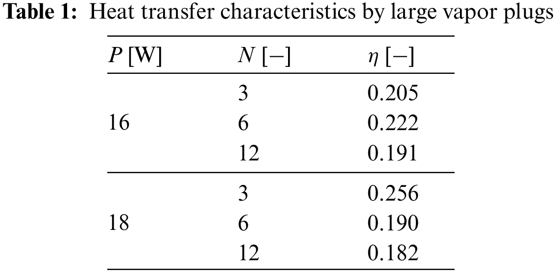
η = 0.205 was obtained with N = 3 for the three vapor plugs in Fig. 10. In addition, the image analysis using Eqs. (4)–(6) was also conducted by changing N, and the η values at P = 16.0 and 18.0 W were obtained as shown in Table 1. It was found that even if N was increased from 6 to 12, the difference in η was small. The η values at P = 16.0 and 18.0 W both with N = 12 were approximately 0.19. This small value implies that although the generation of large vapor plugs was found one after another in the PHP channels, most of the heat was transferred by using the sensible heat of the working fluid. The latent heat of HFE-7100 is small; its value is 112 kJ/kg [32] and approximately 1/22 of water at 25°C. This property caused the small values of η in the present PHP.
Visualization experiments were conducted for the polymer PHP filled with HFE-7100 as a working fluid. A semi-transparent polymer PHP was fabricated with a plastic 3D printer, and the flow patterns of liquid slugs and vapor plugs of the working fluid were obtained by conducting video analysis. Temperature distributions of the PHP were simultaneously obtained with thermocouples, and the heat transfer characteristics of the PHP were discussed with the flow patterns. The findings obtained in this study can be summarized as follows:
• The semi-transparent polymer PHP was successfully fabricated. Clear flow patterns were obtained by the video analysis.
• Before starting heating, large liquid slugs stayed at the evaporator section of the PHP. After starting heating, the large liquid slugs were divided by boiling, and oscillatory flow of smaller liquid slugs and vapor plugs was found in the PHP.
• Clear circulation flow was found when the power input was larger than 12.0 W. The circulation flow reduced the fluctuations of temperatures and enhanced the heat transfer from the evaporator section to the condenser section of the PHP.
• In the circulation flow mode, large growth and contraction of vapor plugs were found in all even-numbered PHP channels. However, the phase-change heat transfer rate by large vapor plugs was 19% of the total heat transfer rate of the PHP, which implies that most of the heat was transferred by using the sensible heat of the working fluid.
Acknowledgement: The authors would like to thank Mr. Y. Aoyu and Mr. Y. Sugano for their help in conducting the experiments.
Funding Statement: This work was supported by JSPS KAKENHI Grant Number 22K03947.
Author Contributions: The authors confirm contribution to the paper as follows: study conception and design: N. Nagasato, Z. Pei, Y. Koito; data collection: N. Nagasato, Z. Pei; analysis and interpretation of results: N. Nagasato, Z. Pei, Y. Koito; draft manuscript preparation: Z. Pei, Y. Koito. All authors reviewed the results and approved the final version of the manuscript.
Availability of Data and Materials: The data are available from the corresponding author upon reasonable request.
Conflicts of Interest: The authors declare that they have no conflicts of interest to report regarding the present study.
References
1. Tang, Y., Yuan, D., Lu, L., Wang, Z. (2013). A multi-artery vapor chamber and its performance. Applied Thermal Engineering, 60(1–2), 15–23. [Google Scholar]
2. Solomon, A. B., Ramachandran, K., Asirvatham, L. G., Pillai, B. C. (2014). Numerical analysis of a screen mesh wick heat pipe with Cu/water nanofluid. International Journal of Heat and Mass Transfer, 75, 523–533. [Google Scholar]
3. Schampheleire, S. D., Kerpel, K. D., Deruyter, T., Jaeger, P. D., Paepe, M. D. (2015). Experimental study of small diameter fibres as wick material for capillary-driven heat pipes. Applied Thermal Engineering, 78, 258–267. [Google Scholar]
4. Boo, J. H., Kim, H. G. (2017). Experimental study on the performance characteristics of a cylindrical heat pipe having a screen wick subject to multiple heat sources. Applied Thermal Engineering, 126, 1209–1215. [Google Scholar]
5. Mahdavi, M., Tiari, S., Schampheleire, S. D., Qiu, S. (2018). Experimental study of the thermal characteristics of a heat pipe. Experimental Thermal and Fluid Science, 93, 292–304. [Google Scholar]
6. Akachi, H. (1990). Structures of a heat pipe. U.S. Patent No. 4921041. [Google Scholar]
7. Han, X., Wang, X., Zheng, H., Xu, X., Chen, G. (2016). Review of the development of pulsating heat pipe for heat dissipation. Renewable and Sustainable Energy Reviews, 59, 692–709. [Google Scholar]
8. Bastakoti, D., Zhang, H., Li, D., Cai, W., Li, F. (2018). An overview on the developing trend of pulsating heat pipe and its performance. Applied Thermal Engineering, 141, 305–332. [Google Scholar]
9. Ayel, V., Slobodeniuk, M., Bertossi, R., Romenstant, C., Bertin, Y. (2021). Flat plate pulsating heat pipes: A review on the thermohydraulic principles, thermal performances and open issues. Applied Thermal Engineering, 197, 117200. [Google Scholar]
10. Nikolayev, V. S. (2021). Physical principles and state-of-the-art of modeling of the pulsating heat pipe: A review. Applied Thermal Engineering, 195, 117111. [Google Scholar]
11. Ling, Y. Z., She, X. H., Zhang, X. S., Chen, T. T., Lin, X. R. et al. (2022). A PCM-based thermal management system combining three-dimensional pulsating heat pipe with forced-air cooling. Applied Thermal Engineering, 213, 118732. [Google Scholar]
12. Zhang, D., He, Z., Guan, J., Tang, S., Shen, C. (2022). Heat transfer and flow visualization of pulsating heat pipe with silica nanofluid: An experimental study. International Journal of Heat and Mass Transfer, 183, 122100. [Google Scholar]
13. Yasuda, Y., Nabeshima, F., Horiuchi, K., Nagai, H. (2022). Visualization of the working fluid in a flat-plate pulsating heat pipe by neutron radiography. International Journal of Heat and Mass Transfer, 185, 122336. [Google Scholar]
14. Iwata, N., Bozzoli, F., Pagliarini, L., Cattani, L., Vocale, P. et al. (2022). Characterization of thermal behavior of a micro pulsating heat pipe by local heat transfer investigation. International Journal of Heat and Mass Transfer, 196, 123203. [Google Scholar]
15. Xu, R., Li, X., Lei, T., Wu, Q., Wang, R. (2022). Operation characteristics of a gravity pulsating heat pipe under different heat inputs. International Journal of Heat and Mass Transfer, 189, 122731. [Google Scholar]
16. Li, S., Pei, H., Liu, D., Shen, Y., Tao, X. et al. (2023). Visualization study on the flow characteristics of a nitrogen pulsating heat pipe. International Communications in Heat and Mass Transfer, 143, 106722. [Google Scholar]
17. Zufar, M., Gunnasegaran, P., Kumar, H. M., Ng, K. C. (2020). Numerical and experimental investigations of hybrid nanofluids on pulsating heat pipe performance. International Journal of Heat and Mass Transfer, 146, 118887. [Google Scholar]
18. Parthasarathi, S., Nagarajan, S., Desai, S., Reddy, S. U., Narasimham, G. S. V. L. (2021). Effect of bend radius and insulation on adiabatic section on the performance of a single closed loop pulsating heat pipe: Experimental study and heat transfer correlation. Heat and Mass Transfer, 57, 1871–1892. [Google Scholar]
19. Schwarz, F., Uddehal, S. R., Lodermeyer, A., Bagheri, E. M., Forster-Heinlein, B. et al. (2021). Interaction of flow pattern and heat transfer in oscillating heat pipes for hot spot applications. Applied Thermal Engineering, 196, 117334. [Google Scholar]
20. Ayel, V., Slobodeniuk, M., Bertossi, R., Karmakar, A., Martineau, F. et al. (2022). Thermal performances of a flat-plate pulsating heat pipe tested with water, aqueous mixtures and surfactants. International Journal of Thermal Sciences, 178, 107599. [Google Scholar]
21. Lyu, B., Xu, D., Wang, W., Xin, J., Shi, Y. et al. (2023). Experimental investigation of a serial-parallel configuration helium pulsating heat pipe. Cryogenics, 131, 103668. [Google Scholar]
22. Li, C., Li, J. (2023). Thermal characteristics of a flat plate pulsating heat pipe module for onsite cooling of high power server CPUs. Thermal Science and Engineering Progress, 37, 101542. [Google Scholar]
23. Lin, Y., Kang, S., Wu, T. (2009). Fabrication of polydimethylsiloxane (PDMS) pulsating heat pipe. Applied Thermal Engineering, 29, 573–580. [Google Scholar]
24. Lim, J., Kim, S. J. (2018). Fabrication and experimental evaluation of a polymer-based flexible pulsating heat pipe. Energy Conservation and Management, 156, 358–364. [Google Scholar]
25. Hao, T., Ma, H., Ma, X. (2019). Heat transfer performance of polytetrafluoroethylene oscillating heat pipe with water, ethanol, and acetone as working fluids. International Journal of Heat and Mass Transfer, 131, 109–120. [Google Scholar]
26. Koito, Y., Yoshida, H., Pei, Z. (2021). An experimental study of a polymer pulsating heat pipe 3D-printed on a thin polymer sheet. Multiphase Science and Technology, 33(4), 31–43. [Google Scholar]
27. Alqahtani, A. A., Edwardson, S., Marengo, M., Bertola, V. (2022). Performance of flat-plate, flexible polymeric pulsating heat pipes at different bending angles. Applied Thermal Engineering, 216, 118948. [Google Scholar]
28. Hideyama, F., Koito, Y. (2019). Heat transfer characteristics of an ABS polymer pulsating heat pipe fabricated by a 3-D printer. Thermal Science & Engineering, 27(2), 59–66. [Google Scholar]
29. Pei, Z., Koito, Y. (2023). Fluid distributions and flow characteristics in a polymer pulsating heat pipe: Visualization experiments using HFE as a working fluid. Proceedings of the 33rd International Symposium on Transport Phenomena, Kumamoto, Japan. [Google Scholar]
30. Joint Committee for Guides in Metrology (2008). Evaluation of measurement data—Guide to the expression of uncertainty in measurement. https://www.bipm.org/documents/20126/2071204/JCGM_100_2008_E.pdf (accessed on 06/10/2023) [Google Scholar]
31. Khandekar, S., Groll, M. (2003). On the definition of pulsating heat pipes: An overview. Proceedings of the 5th Minsk International Seminar (Heat Pipes, Heat Pumps and Refrigerators), Minsk, Belarus. [Google Scholar]
32. 3M (2022). Heat transfer applications using 3M™ Novec™ engineered fluids. https://multimedia.3m.com/mws/media/1091997O/3m-novec-engineered-fluids-for-heat-transfer-line-card.pdf (accessed on 02/11/2023) [Google Scholar]
Cite This Article
 Copyright © 2024 The Author(s). Published by Tech Science Press.
This work is licensed under a Creative Commons Attribution 4.0 International License , which permits unrestricted use, distribution, and reproduction in any medium, provided the original work is properly cited.
 Downloads
 Citation Tools