
 Submit a Paper
 Propose a Special lssue
 Open Access
ARTICLE

Performance Optimization of a U-Shaped Liquid Cooling Plate: A Synergistic Study of Flow Guide Plate and Spoiler Columns
School of Energy and Safety Engineering, Tianjin Chengjian University, Tianjin, 300384, China
* Corresponding Author: Jing Hu. Email:
(This article belongs to the Special Issue: Fluid Flow, Heat and Mass Transfer within Novel Cooling Structures)
Frontiers in Heat and Mass Transfer 2025, 23(3), 957-974. https://doi.org/10.32604/fhmt.2025.064892
Received 26 February 2025; Accepted 07 May 2025; Issue published 30 June 2025
 View Full Text
 Download PDF
Abstract
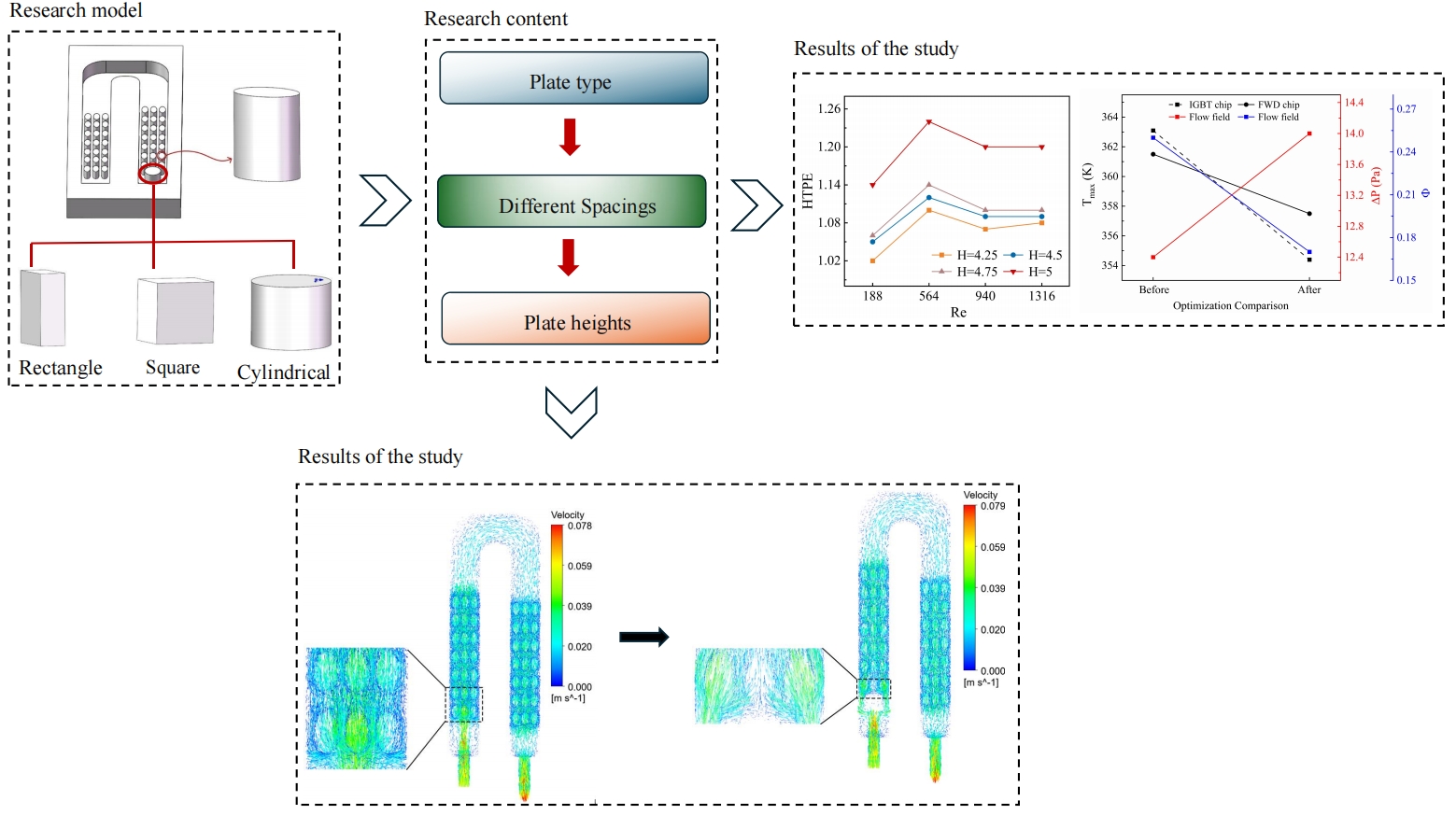
As a core power device in strategic industries such as new energy power generation and electric vehicles, the thermal reliability of IGBT modules directly determines the performance and lifetime of the whole system. A synergistic optimization structure of “inlet plate-channel spoiler columns” is proposed for the local hot spot problem during the operation of Insulated Gate Bipolar Transistor (IGBT), combined with the inherent defect of uneven flow distribution of the traditional U-type liquid cooling plate in this paper. The influences of the shape, height (H), and spacing from the spoiler column (b) of the plate on the comprehensive heat dissipation performance of the liquid cooling plate are analyzed at different Reynolds numbers, A dual heat source strategy is introduced and the effect of the optimized structure is evaluated by the temperature inhomogeneity coefficient (Φ). The results show that the optimum effect is achieved when the shape of the plate is square, H = 4.5 mm, b = 2 mm, and u = 0.05 m/s, at which the HTPE = 1.09 and Φ are reduced by 40%. In contrast, the maximum temperatures of the IGBT and the FWD (Free Wheeling Diode) chips are reduced by 8.7 and 8.4 K, respectively, and ΔP rises by only 1.58 Pa while keeping ΔT not significantly increased. This optimized configuration achieves a significant reduction in the critical chip temperature and optimization of the flow field uniformity with almost no change in the system flow resistance. It breaks through the limitation of single structure optimization of the traditional liquid cooling plate and effectively solves the problem of uneven flow in the U-shaped cooling plate, which provides a new solution with important engineering value for the thermal management of IGBT modules.Graphic Abstract
Keywords
IGBT combines the high input impedance of a Metal-Oxide-Semiconductor Field-Effect Transistor (MOSFET) and the low on-state voltage drop characteristics of a Bipolar Junction Transistor (BJT) [1]. It is widely used in various fields such as smart grid, new energy vehicles, wind power generation, and rail transportation [2,3]. Studies have shown that temperature factors account for 55% of the causes of IGBT module failure [4]. In the process of miniaturization and accuracy improvement of the device, the hot spot region is often accompanied by a high heat flux phenomenon, which leads to uneven temperature distribution inside the chip, which may lead to module failure [5]. Insufficient heat dissipation can cause the IGBT module temperature to approach the critical value rapidly, which seriously affects the electrical performance and shortens the service life [6]. Currently, there are air-cooled, liquid-cooled, heat pipe, and phase change thermal management methods for IGBT module heat dissipation [7]. Air-cooled heat dissipation includes natural convection and forced convection, natural convection is difficult to meet the demand for high power density due to low cooling efficiency [8], and forced convection cooling is more efficient, but there are problems of high noise and uneven temperature [9]. Phase change cooling has good temperature uniformity, but the high cost and dependence on the work mass constrain industrial applications [10]. Heat pipe heat dissipation is more efficient but suffers from high cost and dependence on gravity [11]. Liquid-cooled heat dissipation has become the focus of research on heat dissipation in high-power electronics due to its advantages of efficient heat transfer and breakthrough of traditional limitations [12]. The latest research shows that heat transfer efficiency can be greatly improved by constructing micro-channel liquid cooling plates by adding fins or spoilers in the flow channel [13]. Ref. [14] designed 10 kinds of curved fin structure shapes for optimization based on the curvature and degree of curvature of square fins inward or outward, and added three shapes of secondary fins, triangular, square, and circular in the center of every four primary fins to optimize the comprehensive heat transfer performance of liquid cooling plate. Ref. [15] proposed a new type of I-shaped pin fins due to its greater heat transfer surface area to volume ratio and streamlined shape, which is more conducive to heat transfer and fluid flow. The height, thickness, and orientation angle of the fins were studied to determine the optimum configuration and angle. Ref. [16] optimized the liquid cooling plate structure by combining the topology optimization method with an array of fins having different pins. Ref. [17] designed a special-shaped pin fin and studied the effects of fin height ratio, width-length ratio, width-ratio, and spacing ratio on the comprehensive heat transfer performance of the liquid cooling plate, and using the temperature inhomogeneity coefficient to quantify the degree of fluid distribution inhomogeneity. Ref. [18] constructed six letter-type fin structures, such as type I, type O, type T, type Y, type C, and inverted V, and the synergistic effect and thermal irreversibility of the flow and temperature fields were discussed and analyzed at eight Reynolds numbers. Ref. [19] studied based on three fin shapes (rectangular, circular, and conical) at different liquid mass flow rates, and inlet coolant temperatures. Ref. [20] studied the effects of rectangular fin width and channel width on heat dissipation performance by cutting rectangular microchannels on round copper specimens to improve boiling heat transfer 5 characteristics. Ref. [21] used 25 baffles with different geometric parameters and used the ANN model to determine the effects of horizontal spacing, angle of attack, and vertical spacing of baffles on Nu and ΔP. A new type of U-shaped channel cold plate with wing fins was proposed to improve the flow rate and thermal uniformity [22]. Ref. [23] introduced an optimized U-turn type cold plate inlet and the shape of the baffle by using a discrete concomitant method. Ref. [24] carries out cooling analysis on two arrangement modes of rhomboid microneedle fins in a straight line and staggered under SiO2-water nanofluids with different Reynolds numbers and particle volume fractions. Eight different inlet and outlet configurations were proposed in [25], and the secondary channel angle and the distance between the pin fins were optimized to improve the efficiency of the serpentine channel and homogenize the temperature.
In summary, the uneven flow inside the liquid cooling plate will exacerbate the hot-spot effect of the IGBT module and increase the risk of thermal runaway. Existing researches are mostly optimized using passive heat transfer enhancement such as spoiler columns or heat dissipation fins, but they are mainly confined to the independent regulation of a single structural parameter, which is also the case for the optimization of U-type liquid cooling plates. The inherent structure of the flow channel can easily lead to uneven flow distribution on both sides of the channel. To improve the flow distribution and reduce the maximum temperature of the heat source, this study arranges elliptical spoiler columns in the flow channel and combines the inlet plate to explore the synergistic optimization effect of the two. This innovative design optimizes the flow distribution and improves the cooling uniformity and heat dissipation efficiency. It not only provides a new theoretical basis for the practical application of U-shaped liquid cooling plates but also has important engineering application value in the field of heat dissipation of new energy power generation, electric vehicles, industrial drive, and so on.
As shown in Fig. 1a, the liquid cooling plate is designed as a conventional U-shaped channel with a channel depth of 5 mm, an inlet and outlet diameter of 4 mm, and is made of aluminum, and its material properties are shown in Table 1. 3 rows of 7 columns of oval-shaped spoiler columns with a long axis of 4.0 mm, a short axis of 2.25 mm, and a height of 3 mm are evenly arranged in the flow channel to improve fluid mixing and improve heat transfer performance. Fig. 1b shows the detailed dimensions of the internal flow channel. To quantify the non-uniformity of the temperature distribution within the flow channel, 5 monitoring points are set at y = 12 mm directly below the two heat sources. The spacing between the spoiler columns and plate (denoted as b) is varied between 1 mm and 2.5 mm and is studied in incremental steps of 0.5 mm, with an initial setting of b = 1.5 mm. The square, cylindrical and, rectangular plate shapes are shown in Fig. 2, and the initial height is set to H = 4.5 mm. The parameter ranges between 3.5 and 5 mm in 0.5 mm incremental steps.
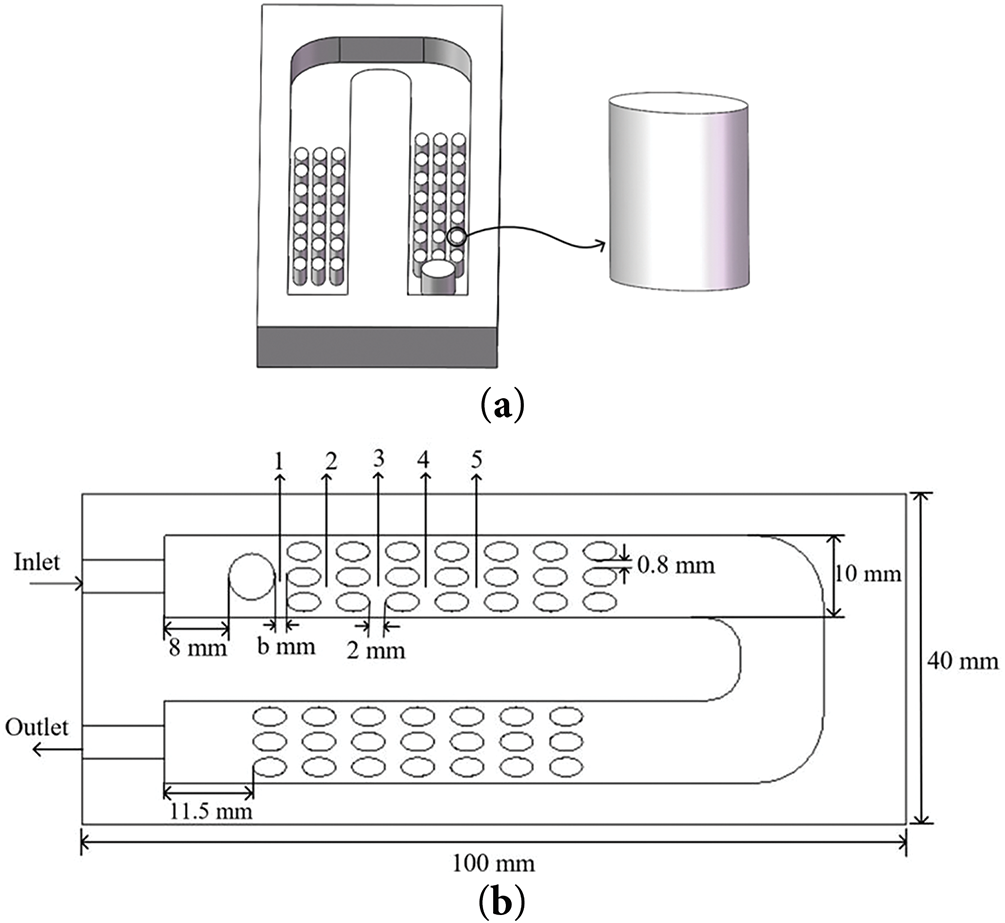
Figure 1: Structure diagram (a) Liquid cooling plate model; (b) Liquid cooling plate internal detail sizes

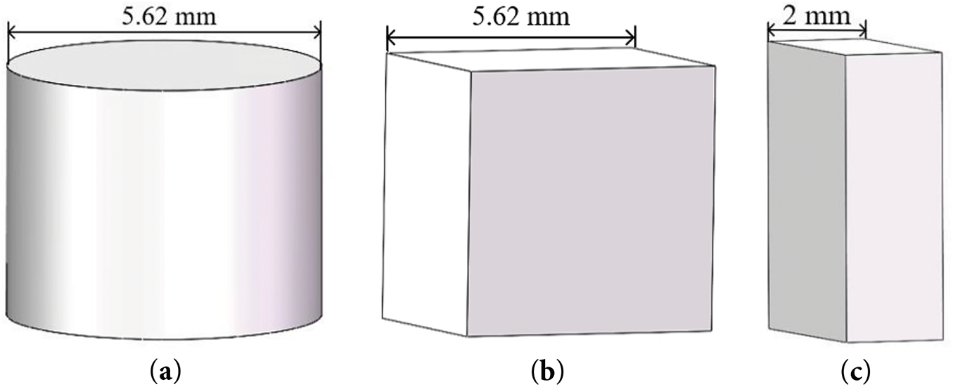
Figure 2: Three plate shapes (a) Cylindrical; (b) Square; (c) Rectangular
3.1 Model Assumptions and Control Equations
Simulation analysis is carried out based on three-dimensional steady state conditions and the following basic assumptions are used in the modeling process:
(1) All materials used are isotropic and the medium is an incompressible Newtonian fluid [26];
(2) Neglecting the effects of thermal radiation and gravity [27];
(3) In view of the low flow rate of the cooling medium, good thermal conductivity and the absence of an internal heat source, the influence of viscous dissipation and thermogenesis effects are neglected [28].
The simulation calculation establishes the three major based on the classical conservation laws and the set of control equations simplified by the above assumptions is expressed as follows:
Mass conservation equation:
where,
Momentum conservation equation:
where, ρ is the fluid density, p is the fluid pressure; μ is the hydrodynamic viscosity.
Energy conservation equation:
where, cp is the constant pressure specific heat capacity of the fluid; k is the thermal conductivity of the fluid; T is the temperature.
In the field of fluid mechanics, the Reynolds number is a dimensionless quantity that describes the flow regime and is used to differentiate between laminar and turbulent flow regimes. It is calculated as follows:
where, Dh is the hydraulic diameter of the liquid cooling plate, which for non-circular channels is calculated as:
The Prandtl number (Pr) is used to characterize the thermophysical properties of the fluid and is calculated as:
The total flow rate (Q) of the control fluid in a liquid cooling plate is defined as:
where, uin is the inlet velocity of the fluid; Ab is the inlet area of the liquid cooling plate.
Nu represents the dimensionless number of convective heat transfer efficiency. The formula is as follows:
where, h is given by the following formula:
where, h is the convective heat transfer coefficient; q is the heat flux; Tave is the average temperature of the liquid cooling plate surface; Tin and Tout are the average temperatures of the fluid inlet and outlet, respectively; ρ, u, μ and k are the density, flow rate, dynamic viscosity and thermal conductivity of the fluid, respectively; A and B represent the length and width of the channels.
The ΔT of the chip is used to evaluate the cooling effect of the liquid cooling plate:
where, Tmax is the maximum temperature of the chip surface; Tmin is the minimum temperature of the chip surface.
The flow field pressure drop formula is as follows:
where, Pin and Pout represent the weighted average total pressure at the inlet and outlet surfaces of the liquid cooling plate, respectively.
The hydraulic thermal performance coefficient combines pressure drop and heat transfer efficiency. It is calculated as follows:
where, Nu0 and ΔP0 are initial values, and this study represents the respective values without plate.
According to [29], the temperature non-uniformity coefficient is introduced to quantify the degree of uneven distribution of fluid in the flow field:
where, Tmax, Tmin indicate the magnitude of the maximum and minimum temperature in the channel.
3.3 Setting of Boundary Conditions
The inlet is defined as a velocity boundary condition, the outlet is defined as a pressure boundary condition. The fluid medium is selected as water, and the inlet water temperature is 298 K. The physical parameters at this temperature are shown in Table 1. In the simulation, the adjacent IGBT and FWD chips at the inlet are used as heat sources, and the heat generation rate of each chip is 1.05 × 10⁷ kW/m³. The simulation process is carried out at u = 0.01–0.07 m/s in steps of 0.02 m/s for four different flow rates, and according to Eq. (7) the total coolant flow rates are 1.2 × 10⁻⁷, 3.6 × 10⁻⁷, 6 × 10⁻⁷, and 8 × 10⁻⁷ m/s, respectively. From Eq. (4), the Re is 188, 654, 940, and 1316, which are lower than 2300, and the laminar flow model is selected. Due to the existence of a flow guide plate and a large number of spoiler columns in the flow channel, the fluid generates localized turbulence on both sides, leading to sharp edges and other complex flow phenomena. To capture these disturbances more accurately, the k-ω turbulence model is finally chosen, which shows higher predictive accuracy in the simulation of low Reynolds number flow and near-wall flow. ANSYS Fluent software is used to carry out to perform 3D steady-state flow simulation, based on the finite volume method with a separated solver. The pressure-velocity coupling is handled by the SIMPLE algorithm during the solution process. The convective term is in second-order windward format and the viscous term is in center-differential format. The residual convergence criterion for each equation is set to 10–6. The natural convection coefficient is set to 10 W/(m2·K) considering the effect of natural convection in air [30].
The meshing is carried out using the integrated meshing function in ANSYS Fluent in the case of no plate and Re = 940. Four different sizes, 0.45, 0.55, 0.65, and 0.75 mm are used for meshing. Optimizing the boundary layer of the fluid domain, the height of the first mesh layer will be the same as the minimum size of the face mesh, while the height of the mesh in the subsequent layers will be increased according to a growth rate of 1.2. By comparing the effect of different mesh numbers on the maximum temperature of IGBT and FWD chips and pressure drop in the flow field. As shown in Fig. 3, when the number of meshes reaches 840,000, the change of these three parameters tends to be flat. At this point, further increasing the number of meshes will not significantly improve the simulation results but will increase the computational cost and complexity. Thus, 0.55 mm is chosen as the meshing size, and this choice is also applicable to other modeled structures. The selected mesh is shown in Fig. 4.
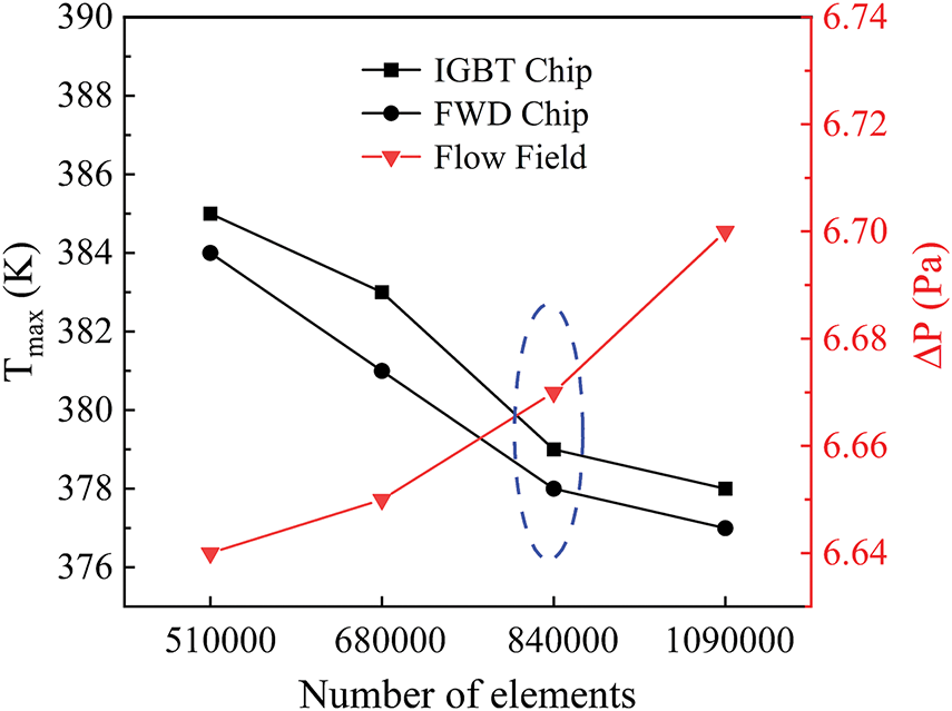
Figure 3: Mesh independence test
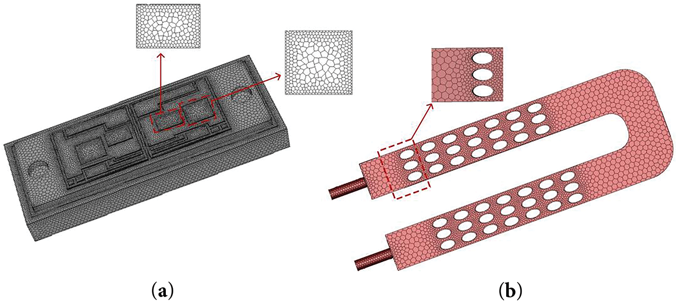
Figure 4: Mesh model (a) Solid domain; (b) Fluid domain
3.5 Numerical Scheme Verification
The validation of the model and methodology in numerical simulation is a key aspect to ensure the reliability of the results. The simulation model and settings are consistent with the Qian et al. [26], and the locations of the nine monitoring points of the liquid cooling plate are also consistent with the reference. The temperatures of the monitoring points of the simulation results are compared with the experimental data in the reference, as shown in Fig. 5, the maximum error occurs in the monitoring point 9, which is only 4.1% from the reference simulation, proving the accuracy of the model established in this study.
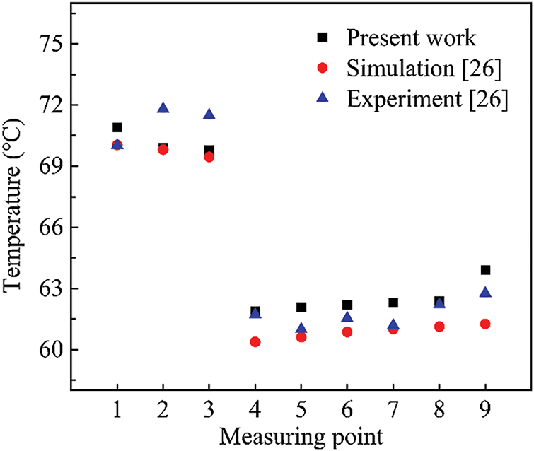
Figure 5: Comparison of results [26]
4.1.1 Heat Transfer and Flow Characterization
The type of plate is represented by the first letter of each plate shape. Fig. 6 shows the influence of the shape of the plate on the chip temperature and ΔP at different flow rates. The maximum temperature and ΔT of the IGBT chip are higher than that of the FWD chip due to the large heat area. The plate improves the cooling uniformity and enhances the comprehensive heat transfer effect by optimizing the flow distribution; however, it also changes the flow field structure, which accelerates the flow rate on both sides and slows down in the middle, resulting in uneven local heat transfer and ΔT increased. At low flow rates, the square plate has the largest contact area and sharp edges to produce strong fluid separation, optimal heat dissipation performance, and the lowest chip temperature. Cylindrical plate has a smoother flow with weaker separation and slightly lower heat transfer efficiency due to its streamlined design; rectangular plate is in the middle of the performance. The differences between the shapes decreases at high flow rates. As shown in Fig. 6c, the plates all increased ΔP, with the square and rectangular plates having a significant effect, while the cylindrical streamlined design has the smallest increase in ΔP.
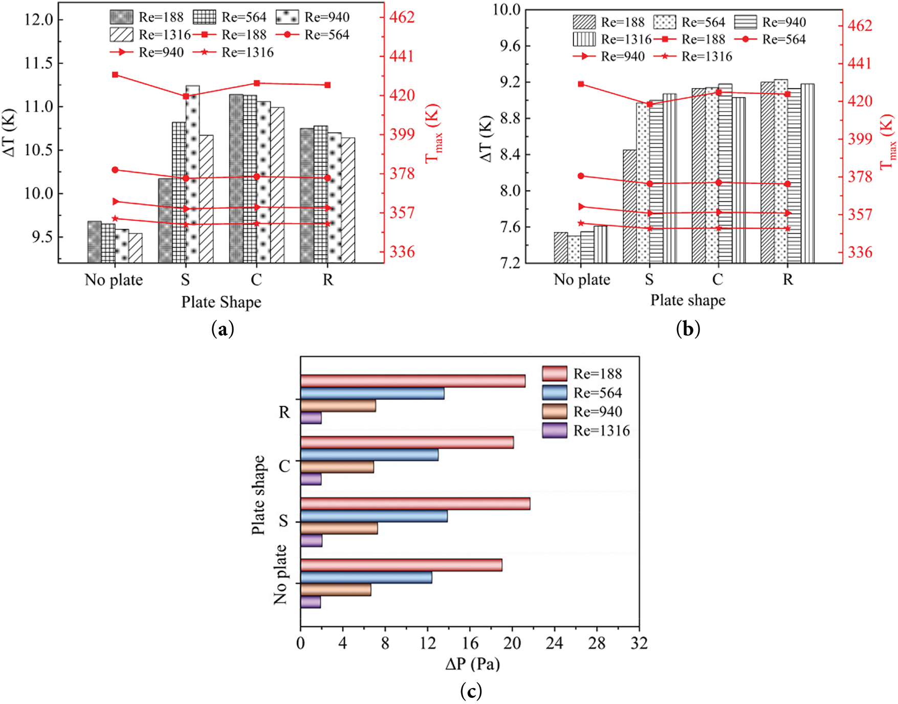
Figure 6: Influence of plate shapes on Tmax and ΔT of the chips and ΔP at different Re (a) IGBT chip; (b) FWD chip; (c) ΔP
Fig. 7 compares the effect of shape on the flow velocity distribution cloud: without the plate, there are top and bottom flow stagnation zones and the thermal boundary layer is thicker; after the addition of the plate, Fig. 7b–d shows that the fluid distribution is significantly improved, and the edge flow velocities are effectively boosted by the interfering flow directions. The square and rectangular plates produce symmetric flow separation by virtue of the right-angled edges, while the curved surface characteristics of the cylindrical plate still make most of the fluid flow concentrated in the middle.
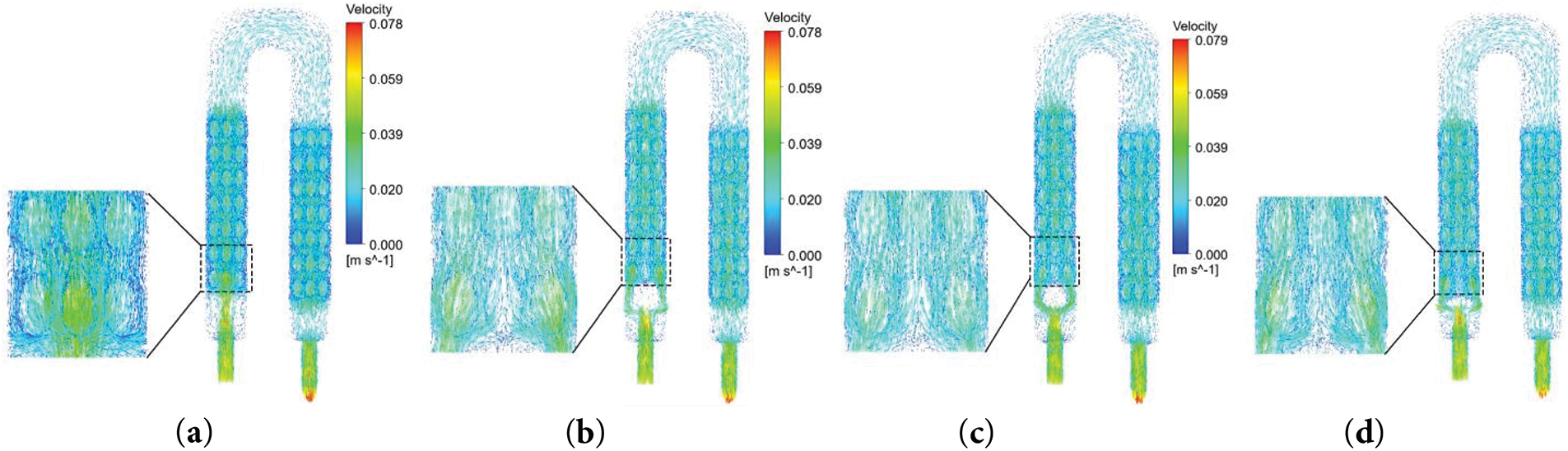
Figure 7: Velocity distribution cloud for different plate shapes at Re = 940 (a) No plate; (b) Square; (c) Cylindrical; (d) Rectangular
4.1.2 Comprehensive Performance
Fig. 8a shows the order of Nu/Nu0 for each plate at different Reynolds numbers: S > R > C. The square plate has the highest Nu due to the large-scale vortices generated by the sharp corners; the cylindrical curved surface makes the flow separation smooth, and the rectangular plate has the lowest heat transfer area utilization, resulting in Nu are smaller than the square baffle. When the flow rate increases to a certain extent, due to the decrease of fluid residence time, the increase of pressure loss, and the saturation of heat transfer area and other factors, the improvement of the flow rate on the heat transfer effect becomes not obvious, and the rising trend of Nu/Nu0 slows down. Fig. 8b shows that when the shape of the plate is Re = 188, 564, the fluid velocity is small, the fluid flow is not mixed or vortex and other complex phenomena, and the fluid flow is relatively stable and orderly. In addition, its heat transfer area is small, and ΔP has almost no effect. In addition, its heat transfer area is small and ΔP has almost no effect. When the flow velocity increases (Re = 940, 1316), ΔP increases for each shape of plate. The square plate with 90° angles has the largest ΔP compared to the other three types. Fig. 8c shows that the limited Nu enhancement of the cylindrical plate and the accompanying increase in ΔP leads to some HTPE < 1, which is not favorable for heat transfer enhancement. The HTPE of the remaining two plates is greater than 1, and the square plate providing the most prominent enhancement.
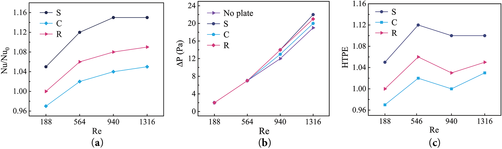
Figure 8: Variations of Nu/Nu0, ΔP, HTPE for plate shapes against Re (a) Nu/Nu0; (b) ΔP; (c) HTPE
4.1.3 Temperature Inhomogeneity
Table 2 gives the effect of plate shape on the temperature inhomogeneity coefficient for two typical Re. The largest temperature inhomogeneities occur in channels 2, 3, and 4, which are directly below the heat source. Due to the closest proximity to the heat source, these channels receive the highest density of heat flow, resulting in the steepest thermal gradient. As the distance from the heat source increases, the temperature inhomogeneity decreases, indicating that the heat source influence diminishes with distance and the temperature distribution becomes uniform. Both the inclusion of the plate and the flow rate enhancement can effectively reduce the channel temperature inhomogeneity. The unique geometry of the square plate distributes the fluid uniformly across the five channels and provides the largest fluid-solid contact area with the lowest Φ. Cylindrical plate is not as effective in distributing the fluid, with a bias toward the center channel, resulting in higher temperatures in both channels. Rectangular plate is in the middle of the performance.

The above analysis shows the square plate significantly improves the heat dissipation performance and the ΔP increases by only 1.47 Pa. However, it will increase the ΔT, and the ΔT of the IGBT and FWD chips increases by 1.41 and 1.45 K at Re = 940, respectively, which affects the reliability of the IGBT module. The subsequent optimization objective will be optimized by balancing the pressure drop with improving the temperature uniformity.
4.2 Effect of Spacing between Plate and Spoiler Columns
4.2.1 Heat Transfer and Flow Performance Analysis
Fig. 9 gives the effect of the spacing between the plate and the spoiler columns on the chip temperature and ΔP. b = 2 mm has the optimal heat dissipation effect, and the maximum temperature and ΔT of the IGBT chip at Re = 940 are reduced by 4.78 and 0.91 K, respectively, compared with the initial spacing; at the same time, the FWD chip is also reduced by 4.78 and 0.6 K, respectively. Appropriately increasing the spacing can maintain the perturbation to strengthen the heat transfer, but it is too small to lead to insufficient heat transfer, too large is to weaken the plate shunt effect. Observing Fig. 9c, the higher the flow velocity, the higher the ΔP. The effect of different spacing on ΔP is very small, and it only varies in the region of 13.8 Pa–14 Pa for Re = 940. The effect of different spacing on the velocity cloud diagram of the flow field is shown in Fig. 10. The fluid distribution is optimal when b = 1 mm and b = 2 mm, but the small spacing will increase the flow velocity and flow resistance due to the reduction of the flow cross-sectional area. When b = 1.5 mm, the backflow phenomenon in the middle channel is significant, which reduces the effective cooling area of the fluid per unit time; and after increasing to 2.5 mm, the tendency of fluid distribution to both sides is reduced.
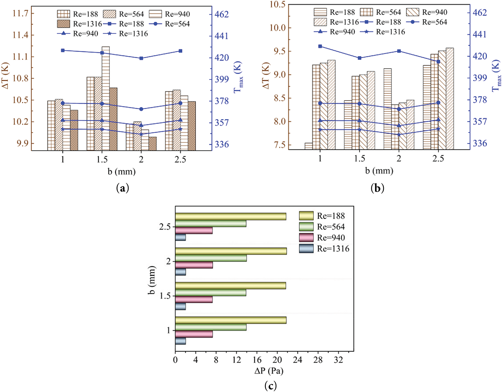
Figure 9: Variation of Tmax, ΔT for chips and ΔP with spacings at different Re (a) IGBT chip; (b) FWD chip; (c) ΔP
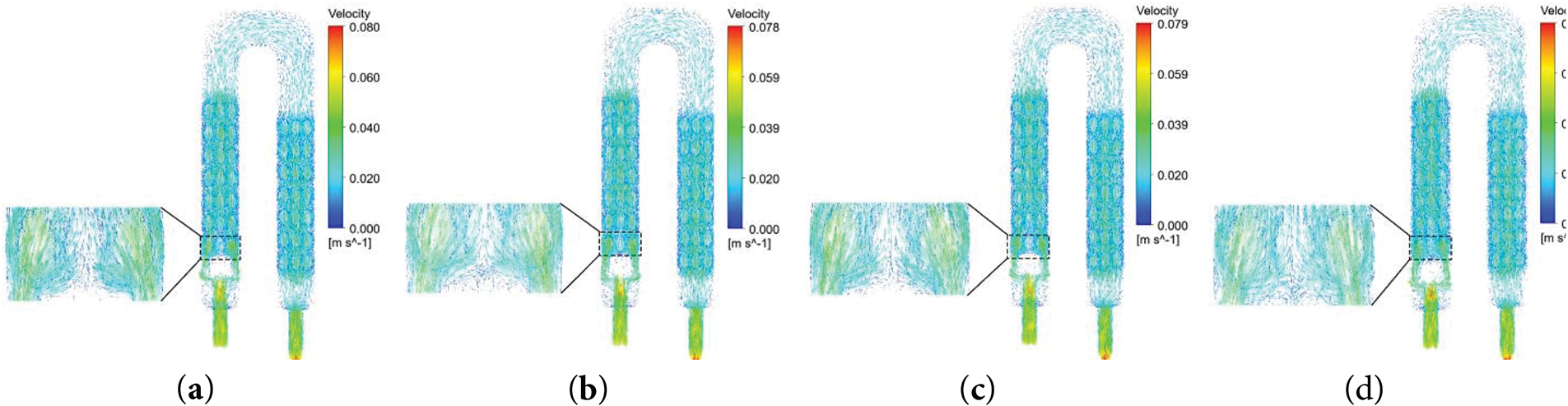
Figure 10: Velocity distribution cloud for different spacings at Re = 940 (a) b = 1; (b) b = 1.5; (c) b = 2; (d) b = 2.5
4.2.2 Comprehensive Performance Studies
The effect of different spacings on Nu/Nu0 are shown in Fig. 11a. At low Reynolds numbers (Re = 188, 564), small spacing enhances the laminar flow disturbance and improves the heat transfer efficiency. At high Reynolds numbers (Re = 940, 1316), inertial forces prevail, and too small a spacing increases dissipation due to flow separation, while a larger spacing is more conducive to turbulent mixing. Fig. 11b shows that the influence of different spacings on the pressure loss in the flow field is negligible, which means that the pressure loss is mainly affected by the overall flow channel design and has little to do with the spacing. The combined changes of the two are shown in Fig. 11c. At low flow rates, ΔP remains stable while Nu/Nu0 increases significantly, resulting in an increasing and then slowing down trend in the comprehensive heat transfer performance. Since the increase of Nu/Nu0 is always larger than the increase of ΔP, HTPE are all larger than 1.
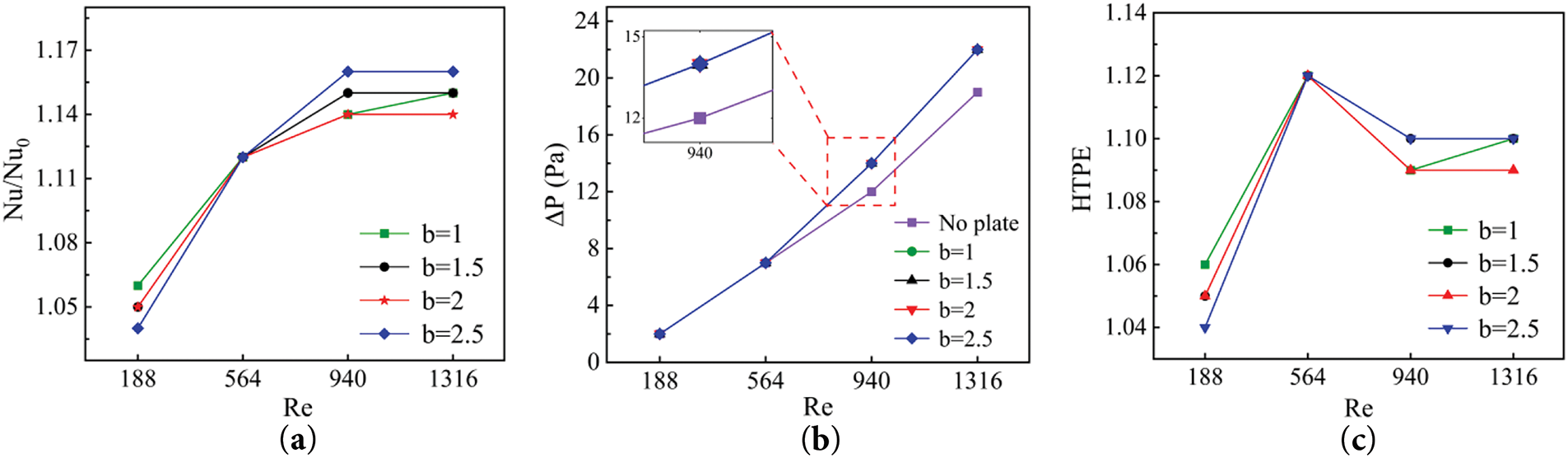
Figure 11: Variations of Nu/Nu0, ΔP, HTPE for different spacings against Re (a) Nu/Nu0; (b) ΔP; (c) HTPE
4.2.3 Temperature Inhomogeneity
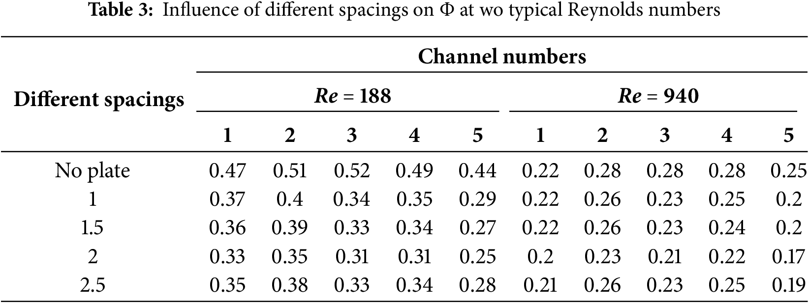
The effect of different spacing between the plate and the spoiler columns on the inhomogeneity coefficients in the channels are shown in Table 3. b = 2 mm when the five channels in the two flow rates Φ have reached the minimum value, at this time, the plate’s deflecting effect and the spoiler columns to achieve the optimal match, the fluid distribution is uniform. When the spacing is too small (b = 1 mm), it is difficult to fully diffuse the fluid in the narrow channel, forming a local high-temperature zone. b = 1.5 mm, the flow resistance and the disturbance effects has not reached the optimal balance, and the middle disturbance column partially has uneven flow or insufficient disturbance. When the spacing is too large (b = 2.5 mm), the diverting effect of the plate is weakened, which directly leads to the temperature of the two sides of the channel is higher than that of the middle channel.
4.3.1 Heat Transfer and Flow Characterization
Fig. 12a,b shows that the effect of the plate height on the maximum temperatures of the IGBT and FWD chips tends to level off at Re = 940 (u = 0.05 m/s), and ΔT is small at this point, and continuing to increase the flow velocity will only significantly increase the pressure drop in the flow field, thus enhancing the energy consumption of the system. Under the critical flow rate condition, when the plate maintains the initial height of H = 4.5 mm, the maximum temperatures of IGBT and FWD chips reach the optimal value, and the ΔT of both of them is also lower. Too low or too high a plate height will lead to insufficient heat transfer and obstruction of the flow path, thus weakening the heat dissipation effect. Under the critical flow rate condition, when the plate maintains the initial height of H = 4.5 mm, the maximum temperature of the IGBT and FWD chips reaches the optimal value, and the ΔT of both of them is also lower. Too low or too high a height of the plate will lead to insufficient heat transfer and obstruction of the flow path, thus weakening the heat dissipation effect. As shown in Fig. 12c, under the optimal flow rate, ΔP fluctuates only within 13.8 Pa–14.1 Pa at the optimal flow rate, which indicating that the optimized structure can achieve improved heat dissipation performance with almost no increase in pump power consumption. Fig. 13 shows the influence of the plate height on the fluid distribution. At H = 4.25 mm, the cooling medium mainly passes over the plate, and the middle channel is heavily shunted, while the two sides are insufficiently shunted. After optimization to H = 4.5 mm, the flow bias phenomenon is improved, and H = 4.75 mm produces a larger return vortex, which is detrimental to heat transfer. When the height of the plate is equal to the depth of the flow channel, the passage rate of the upper channel is significantly reduced, weakening the heat exchange effect of the plate in contact with the fluid.
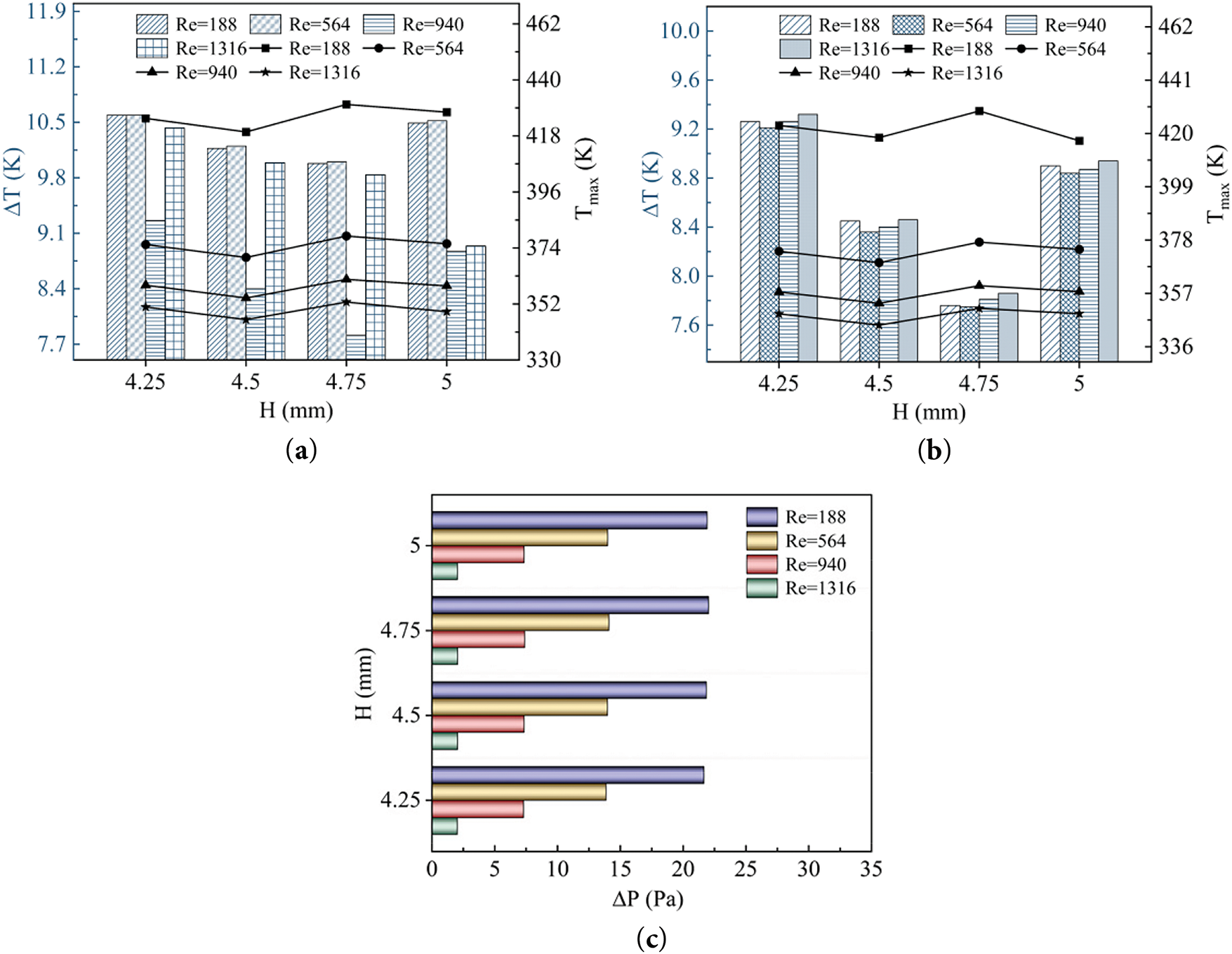
Figure 12: Variation of Tmax, ΔT for chips and ΔP with plate heights at different Re (a) IGBT chip; (b) FWD chip; (c) ΔP
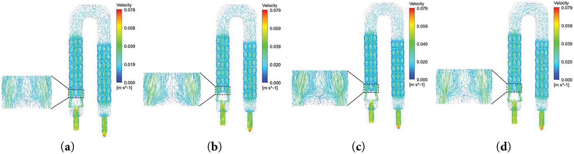
Figure 13: Velocity distribution clouds for different plate heights at Re = 940 (a) H = 4.25; (b) H = 4.5; (c) H = 4.75; (d) H = 5
4.3.2 Comprehensive Characterization
Fig. 14a shows that the order of Nu/Nu0 is 5 > 4.75 > 4.5 > 4.25, which are all greater than 1. This phenomenon clearly reveals that the height of the plate has a significant positive correlation with the heat transfer enhancement effect: on the one hand, increasing the height expands the contact area of the fluid-solid and provides a larger surface for heat transfer; on the other hand, it promotes the formation of the secondary vortex and improve the Nu. The growth rate of Nu/Nu0 decreases with increasing Re, indicating that there is a critical threshold for heat transfer enhancement, beyond which the flow velocity contribution becomes saturated. Fig. 14b shows that the change in plate height has a weak effect on the global flow resistance, as the pressure drop dominated by the spoiler columns is much larger than the local perturbation of the plate. Combined with the Nu and ΔP variations, the order of HTPE is as follows: 5 > 4.75 > 4.5 > 4.25, all of which are greater than 1. It can be further verified that the introduction of the plate is favorable to the comprehensive heat transfer performance.
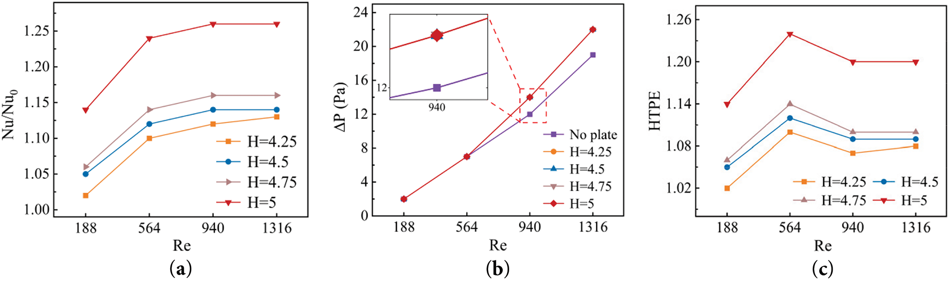
Figure 14: Variations of Nu/Nu0, ΔP, HTPE for plate heights against Re (a) Nu/Nu0; (b) ΔP; (c) HTPE
4.3.3 Temperature Inhomogeneity
Table 4 shows the effect of plate height on the temperature uniformity in the channel for both Re. The distribution of the fluid within the velocity field directly affects its temperature uniformity, and Φ decreases at both flow rates, with a more significant effect at low Reynolds numbers. And all of them reach the minimum value when H = 4.5 mm, at this time, both sides of the plate can produce stable and symmetrical vortex pairs, which promotes the lateral mixing of the fluid. At this point, further increase in height to 4.75 mm will excessively enhance the flow separation. When the height is the same as the fluid channel (H = 5 mm), there will be a weakening of the fluid disturbance in the middle channel. When the height of the plate is small (H = 4.25 mm), the uneven distribution of fluid between the two sides and the middle leads directly to the phenomenon of temperature inhomogeneity in each channel.

(1) The plate layout of the traditional U-shaped liquid cooling plate before the fluid enters the flow field is conducive to alleviating the problem of uneven fluid distribution in the two channels, and the square plate performs the best among the three plate shapes. The optimal flow rate u = 0.05 m/s reduces Φ in the flow channel by up to 20% and achieves a decrease in the maximum temperatures of the IGBT and FWD chips by 3.9 and 2.9 K, respectively, with an increase in ΔP of only 2.64 Pa. However, the ΔT of the IGBT and FWD chips are increased by 1.41 and 1.45 K, respectively.
(2) Through simulation verification, it is found that the appropriate spacing and time development between the plate and the spoiler columns are essential for the effective heat transfer of the fluid. b = 2 mm plate spacing is identified as the optimum design parameter. Compared to the initial value of b = 1.5 mm, Φ is reduced from 0.2 to 0.18 at the optimal flow rate of 0.05 m/s. and the maximum temperature is reduced by 5.3 and 4.9 K for the IGBT and FWD chips, respectively, with a negligible effect on ΔP. Meanwhile, ΔT is reduced by 0.91 and 0.6 K for IGBT and FWD chips, respectively.
(3) The performance is optimized when the initial setting of the plate height is H = 4.5 mm, which indicates its best application in hydrodynamic regulation.
Acknowledgement: Sincere thanks to the reviewers for their valuable comments.
Funding Statement: This research was supported by Tianjin Science and Technology Planning Project (22YDTPJC0020).
Author Contributions: The authors confirm contribution to the paper as follows: Conceptualization, methodology, validation, formal analysis, investigation, data curation, writing—original draft preparation, writing—review and editing, visualization, Jing Hu and Xiaoyu Zhang; supervision, Jing Hu. All authors reviewed the results and approved the final version of the manuscript.
Availability of Data and Materials: Data available on request from the authors.
Ethics Approval: Not applicable.
Conflicts of Interest: The authors declare no conflicts of interest to report regarding the present study.
Nomenclature
| Re | Reynolds number |
| Pr | Prandtl number |
| ρ | Fluid density (kg/m3) |
| u | Fluid velocity (m/s) |
| Dh | Hydraulic diameter (mm) |
| μ | Fluid dynamic viscosity (kg/(m·s)) |
| Ab | Area of water inlet (m2) |
| Q | Total flow rate (m/s) |
| h | Convective heat transfer coefficient (W/(m2·K)) |
| k | Thermal conductivity (W/(m·K)) |
| q | Heat flux (kW/m3) |
| Tave | Average temperature of the liquid cooling plate surface (K) |
| Tin | Average temperatures of the fluid inlet (K) |
| Tout | Average temperatures of the fluid outlet (K) |
| ΔT | Temperature difference (K) |
| T | Temperature (K) |
| p | Pressure (Pa) |
| ΔP | Flow field pressure drop (Pa) |
| ΔP0 | Initial pressure drop value (Pa) |
| Pin | Inlet pressure drop (Pa) |
| Pout | Outlet pressure drop (Pa) |
| Nu | Nusselt number |
| Nu0 | Initial Nusselt number |
| HTPE | Hydraulic thermal performance coefficient |
| Temperature inhomogeneity coefficient | |
| Tmax | Maximum temperature in the flow field (K) |
| Tmin | Minimum temperature in the flow field (K) |
| Abbreviation | |
| A | Channel length (mm) |
| B | Channel width (mm) |
| H | Plate height (mm) |
| b | Spacing between plate and spoiler columns (mm) |
| S | Square plate |
| C | Cylindrical plate |
| R | Rectangular plate |
References
1. Lin X, Wu H, Liu Z, Ying B, Ye C, Zhang Y, et al. Design and analysis of the IGBT heat dissipation structure based on computational continuum mechanics. Entropy. 2020;22(8):816. doi:10.3390/e22080816. [Google Scholar] [PubMed] [CrossRef]
2. Ren Y, Luo W, He Z, Qin N, Meng Q, Qiu M, et al. Development and performance study of a radiation-enhanced heat pipe radiator for cooling high-power IGBT modules. Appl Therm Eng. 2025;262:125307. doi:10.1016/j.applthermaleng.2024.125307. [Google Scholar] [CrossRef]
3. Lee J, Ki S, Seo D, Kim J, Nam Y. Liquid cooling module incorporating a metal foam and fin hybrid structure for high power insulated gate bipolar transistors (IGBTs). Appl Therm Eng. 2020;173(4):115230. doi:10.1016/j.applthermaleng.2020.115230. [Google Scholar] [CrossRef]
4. Arshad A, Jabbal M, Faraji H, Talebizadehsardari P, Bashir MA, Yan Y. Thermal performance of a phase change material-based heat sink in presence of nanoparticles and metal-foam to enhance cooling performance of electronics. J Energy Storage. 2022;48(4):103882. doi:10.1016/j.est.2021.103882. [Google Scholar] [CrossRef]
5. Ansari D, Raza W, Jeong JH, Kim KY. A novel hybrid-composite microchannel heat sink for extreme hotspot mitigation. Int J Therm Sci. 2025;208:109473. doi:10.1016/j.ijthermalsci.2024.109473. [Google Scholar] [CrossRef]
6. Yang S, Guo X, Xu H, Tang F, Zhang B, Zhang Y. Experimental studies on the heat transfer characteristics and instability of a loop thermosyphon with a vertical flat evaporator for IGBT heat dissipation. Appl Therm Eng. 2025;264:125524. doi:10.1016/j.applthermaleng.2025.125524. [Google Scholar] [CrossRef]
7. Chen C, Zhao H, Liu C, Chen J, Liu C, Zhang T, et al. Transient heat transfer characteristics in a flat plate heat sink with mini-channels for cooling high heat flux IGBT. Micromachines. 2022;13(9):1417. doi:10.3390/mi13091417. [Google Scholar] [PubMed] [CrossRef]
8. Ki S, Lee J, Ryu S, Bang S, Kim K, Nam Y. A bio-inspired, low pressure drop liquid cooling system for high-power IGBT modules for EV/HEV applications. Int J Therm Sci. 2021;161:106708. doi:10.1016/j.ijthermalsci.2020.106708. [Google Scholar] [CrossRef]
9. An Z, Gao W, Zhang J, Liu H, Gao Z. Bionic capillary/honeycomb hybrid lithium-ion battery thermal management system for electric vehicle. Appl Therm Eng. 2024;242:122444. doi:10.1016/j.applthermaleng.2024.122444. [Google Scholar] [CrossRef]
10. Zhang X, Tu C, Yan Y. Physics-informed neural network simulation of conjugate heat transfer in manifold microchannel heat sinks for high-power IGBT cooling. Int Commun Heat Mass Transf. 2024;159:108036. doi:10.1016/j.icheatmasstransfer.2024.108036. [Google Scholar] [CrossRef]
11. Fan X, Meng C, Yang Y, Lin J, Li W, Zhao Y, et al. Numerical optimization of the cooling effect of a bionic fishbone channel liquid cooling plate for a large prismatic lithium-ion battery pack with high discharge rate. J Energy Storage. 2023;72:108239. doi:10.1016/j.est.2023.108239. [Google Scholar] [CrossRef]
12. Yang H, Liu N, Gu M, Gao Q, Yang G. Optimized design of novel serpentine channel liquid cooling plate structure for lithium-ion battery based on discrete continuous variables. Appl Therm Eng. 2025;264(1):125502. doi:10.1016/j.applthermaleng.2025.125502. [Google Scholar] [CrossRef]
13. Sohel Murshed SM, Nieto de Castro CA. A critical review of traditional and emerging techniques and fluids for electronics cooling. Renew Sustain Energy Rev. 2017;78(1):821–33. doi:10.1016/j.rser.2017.04.112. [Google Scholar] [CrossRef]
14. Zhang F, Liang B, He Y, Gou H, Zhu Y, Lu F, et al. Study on flow and heat transfer characteristics of phase change synergistic combination finned liquid cooling plate. Int Commun Heat Mass Transf. 2022;138:106377. doi:10.1016/j.icheatmasstransfer.2022.106377. [Google Scholar] [CrossRef]
15. Sallar H, Irfan M, Khan MM, Shahzad MW. Hydro-thermal performance of an I-shaped pin fin microchannel heat sink with variable pin fin height, thickness and orientation. Int Commun Heat Mass Transf. 2025;160(6):108256. doi:10.1016/j.icheatmasstransfer.2024.108256. [Google Scholar] [CrossRef]
16. Duan Z, Xie G, Yu B, Jin P. Multi-objective topology optimization and thermal performance of liquid-cooled microchannel heat sinks with pin fins. Case Stud Therm Eng. 2023;49(2):103178. doi:10.1016/j.csite.2023.103178. [Google Scholar] [CrossRef]
17. Zhang Y, Pan S, Liu S, Liu H, Tian C, Hu J. Effects of one special-shaped pin fin on the flow and heat transfer performance in the liquid cooling plate for a battery pack. Int J Therm Sci. 2024;195(4):108643. doi:10.1016/j.ijthermalsci.2023.108643. [Google Scholar] [CrossRef]
18. Zhang F, Tao J, Gou H, Huang X. Thermal performance analysis of a novel letter-type fin liquid cooling plate based on the field synergy principle and the second law of thermodynamics. Therm Sci Eng Prog. 2024;56(3):103027. doi:10.1016/j.tsep.2024.103027. [Google Scholar] [CrossRef]
19. Wiriyasart S, Naphon P. Heat spreading of liquid jet impingement cooling of cold plate heat sink with different fin shapes. Case Stud Therm Eng. 2020;20:100638. doi:10.1016/j.csite.2020.100638. [Google Scholar] [CrossRef]
20. Al-Obaidy AMH, Fayyadh EM, Al-Dabagh AM. Effect of the geometrical parameter of open microchannel on pool boiling enhancement. Front Heat Mass Transf. 2024;22(5):1421–42. doi:10.32604/fhmt.2024.055063. [Google Scholar] [CrossRef]
21. Zhao S, Yan L, Goyal V, Alghanmi S, Alkhalifah T, Alkhalaf S, et al. Artificial neural network-based optimization of baffle geometries for maximized heat transfer efficiency in microchannel heat sinks. Case Stud Therm Eng. 2023;49(3):103331. doi:10.1016/j.csite.2023.103331. [Google Scholar] [CrossRef]
22. Wang L, Zuo H, Zhang B, Jia G. Effects of the cold plate with airfoil fins on the cooling performance enhancement of the prismatic LiFePO4 battery pack. Energy. 2024;296(4):131210. doi:10.1016/j.energy.2024.131210. [Google Scholar] [CrossRef]
23. Ma H, Su L, He B, He D, Kang Y. New design of U-turn type minichannel cold plate with hybrid fins for high temperature uniformity. Int Commun Heat Mass Transf. 2022;135(4):106078. doi:10.1016/j.icheatmasstransfer.2022.106078. [Google Scholar] [CrossRef]
24. Duangthongsuk W, Laohalertdecha S, Wongwises S. Experimental study on the hydrothermal performance of nanofluids-cooled heat sinks with diamond shape micro pin-fin structures. Int J Thermofluids. 2024;22(5):100691. doi:10.1016/j.ijft.2024.100691. [Google Scholar] [CrossRef]
25. Al-Hasani HM, Freegah B. Influence of secondary flow angle and pin fin on hydro-thermal evaluation of double outlet serpentine mini-channel heat sink. Results Eng. 2022;16:100670. doi:10.1016/j.rineng.2022.100670. [Google Scholar] [CrossRef]
26. Qian G, Dou X, Lu G, Liu H, Wu Q, Jiang R, et al. Parametric study and design of liquid cooling plates for high power density IGBT modules in wind power generation systems. Therm Sci Eng Prog. 2023;43(1):101992. doi:10.1016/j.tsep.2023.101992. [Google Scholar] [CrossRef]
27. Yang W, Zhou F, Liu Y, Xu S, Chen X. Thermal performance of honeycomb-like battery thermal management system with bionic liquid mini-channel and phase change materials for cylindrical lithium-ion battery. Appl Therm Eng. 2021;188:116649. doi:10.1016/j.applthermaleng.2021.116649. [Google Scholar] [CrossRef]
28. Wang Y, Xu X, Liu Z, Kong J, Zhai Q, Zakaria H, et al. Optimization of liquid cooling for prismatic battery with novel cold plate based on butterfly-shaped channel. J Energy Storage. 2023;73:109161. doi:10.1016/j.est.2023.109161. [Google Scholar] [CrossRef]
29. Dąbrowski P. Comparison of various flow maldistribution quantification methods in mini heat exchangers. Sci Rep. 2023;13(1):11482. doi:10.1038/s41598-023-38784-5. [Google Scholar] [PubMed] [CrossRef]
30. Du M, Guo Q, Ouyang Z, Wei K, Hurley WG. Effect of solder layer crack on the thermal reliability of Insulated Gate Bipolar Transistors. Case Stud Therm Eng. 2019;14:100492. doi:10.1016/j.csite.2019.100492. [Google Scholar] [CrossRef]
Cite This Article
 Copyright © 2025 The Author(s). Published by Tech Science Press.
This work is licensed under a Creative Commons Attribution 4.0 International License , which permits unrestricted use, distribution, and reproduction in any medium, provided the original work is properly cited.
 Downloads
 Citation Tools