
 Submit a Paper
 Propose a Special lssue
 Open Access
ARTICLE

Enhancing Hydrothermal Performance of Dimpled Tubes: Investigating the Impact of Different Dimple Sizes and Distribution along the Tube
Mechanical Engineering Department, College of Engineering, Mustansiriyah University, Baghdad, 10047, Iraq
* Corresponding Author: Basima Salman Khalaf. Email:
(This article belongs to the Special Issue: Heat Transfer Enhancement for Energy Applications)
Frontiers in Heat and Mass Transfer 2025, 23(3), 943-956. https://doi.org/10.32604/fhmt.2025.065366
Received 11 March 2025; Accepted 06 May 2025; Issue published 30 June 2025
 View Full Text
 Download PDF
Abstract
The main purpose of this research is to optimize the hydrothermal performance of a dimpled tube by augmenting the surface area for heat transmission and thermal layer cracking. To achieve that, the impact of different dimple diameters and their distribution along the dimpled tube was investigated numerically using the ANSYS Fluent 2022 R1 software by considering two models, A and B. Both models consist of three regions; the first, second, and third have dimple diameters of 3, 2, & 1 mm, respectively. Model A included an in-line dimple arrangement, while model B involved a staggered dimple arrangement. The finite volume method (FVM) was used in the modeling techniques to address the turbulent flow problem, which ranged in this investigation from Re of 3000 to 8000. The cooling fluid used in this investigation is water, which concentrated primarily on single-phase flow conditions. The investigation results revealed that as the Re increased, all analyzed models showcased higher. A reduction in pressure drops, thermal resistance, Nu, and overall performance standards. Crucially, compared to the traditional model, both suggested models demonstrated improved heat transmission capacities. Within all the models examined, the tube with dimples in (model B) as staggered showed the greatest enhancement in the Nu, which was almost double that of the conventional type. Model A and Model B have respective average total performance criteria of 1.23 and 1.34.Keywords
In the previous few decades, researchers have dedicated their efforts to improving the hydrothermal performance and efficiency of heat exchangers. This focus aims to minimize the heat exchangers’ sizes as well as costs while increasing their suitability for a wide range of applications. In general, there exist three primary methods for heat transfer enhancement: passive, active, and both passive & active techniques. The passive technique stands out as the most advantageous because it eliminates the need for external devices, making it low-cost compared to other techniques. Therefore, in the present study, this method has been used to improve the heat exchangers’ thermal performance. To improve heat transfer in heat exchangers by increasing the surface roughness of the tube, using passive techniques. This can be accomplished through the utilization of various configurations such as dimples, ribs, and corrugation. The main goal of these configurations is to enhance flow mixing, intensify turbulent flow, and regenerate the layer of boundary. This ultimately results in noticeable improvements in the heat transfer rate. By using rough surfaces instead of seamless walls, the rate of pressure losses and heat transfer are significantly developed [1,2]. Kaood et al. [3] conducted a numerical investigation of performance for thermal-hydraulic in turbulent flow with conical tubes and dimpled under a constant heat flux. The findings indicated that conical tubes with dimples significantly improved the overall performance of thermal-hydraulic compared to conventional smooth geometries. Additionally, the study revealed that the newly designed convergent tube heat exchanger with dimples demonstrated favorable energy efficiency and positive environmental impacts. Lei et al. [4] conducted a numerical investigation utilizing Response Surface Techniques and a desirability approach. The design parameters selected included the diameter of the dimples, the ratio of depth to diameter, and the spacing ratio between two axially adjacent dimples. The results indicated that the interactive effects within these geometric parameters influence the impact on the overall performance of the dimpled tube. Numerous earlier studies have shown that corrugated tube heat exchangers have relatively good thermal behavior compared to conventional smooth tubes. However, this kind necessitates a strong pump and is distinguished by an adverse pressure drop. Numerous studies have recently looked into the effects of different well shape characteristics, including, Borehole dimensions, including diameter, angle, spacing, and shape, which were examined for the hydrothermal reaction [5–9]. The impact of different inlet flow rates on the performance characteristics of a corrugated tube was investigated by [10–13]. The findings revealed an enhancement in thermal performance; however, there was a significant increase in pressure drop, leading to a decline in overall performance. Another researcher, Rahman Sardar [14] examined the effect of dimplestubes on augmenting heat transfer in forced convection. The results demonstrated that increasing the diameter of the dimples resulted in improved friction factor and heat transfer compared to conventional pipes. Antony and Ganesan [15] conducted a study where they replaced the interior pipe of a heat exchanger using a double pipe with a dimpled tube to enhance heat transfer. They found that there was significant improvement in heat transfer when dimpled tubes were used in heat exchangers. Vicente et al. [16] analyzed the effect of dimples on pressure drop and heat transfer for ten helically dimpled tubes under turbulent fluid flow. They discovered that, under identical flow conditions, the Nu increased by up to 250%, while the increasing for friction factor up to 350%. Nazari et al. [17] examined the number, depth, and placement of dimples that affected the flow and heat transfer characteristics during turbulent flow. They found that, in comparison to a smooth plate, the average Nu has been greater for the surface of the dimpled. However, a drawback of this technique is the increased pressure loss due to higher friction drag and recirculation zones within the dimples. An experimental and numerical study was conducted by Vignesh et al. [18] to evaluate the impact of dimpled tubes on a double-pipe heat exchanger’s hydrothermal effectiveness. The results show that there is a noticeable improvement in the effectiveness of heat transfer when using dimpled tubes compared to traditional tubes. Xie et al. [19] conducted a numerical verification of the thermal performance of dimpled tube heat exchangers with protrusions and dimples. Their findings indicated enhanced heat transfer when using such tubes compared to traditional ones. In another study, Xie et al. [20] analyzed the thermal performance of improved tubes with dimples as cross-ellipsoidal. The findings demonstrated a notable improvement in heat transfer. with both longitudinal and transverse dimples. Falih et al. [21] performed numerical and experimental analyses on concentric heat exchangers utilizing plain and spherical dimpled tubes. The results demonstrated a notable improvement in heat transfer efficiency when dimpled tubes were employed. Rainieri et al. [22] examined the influence of pitch and dimple depth on heat transfer and fluid flow. They observed that the Nu ratio and friction factor ratio increased with greater dimple depth but decreased with increasing pitch. Among the cases studied, the configuration with specific parameters exhibited a maximum value of roughly 2.02 for the Performance Evaluation Criteria (PEC). Finally, Freegah et al. [23] studied the effect of dimple distribution on dimpled tubes’ hydrothermal performance under turbulent flow conditions. They analyzed three angles of dimple distribution and formulated two correlation equations for predicting the Nu and friction factor. The findings indicate that tubes with dimples demonstrate enhanced heat transfer performance. Among the models tested, the 45° angle model exhibited the most notable improvements in both Nu and friction factor. The researchers developed equations with high accuracy rates of 98.96% for predicting friction factor and 96.17% for predicting Nu. Mehrjardi et al. [24] conducted a study aimed at optimizing dimple depth and longitudinal pitch to balance heat transfer efficiency with pressure loss. They used a creative device learning strategy using Generative Adversarial Networks (GANs) to identify optimal dimple configurations. The optimization of performance evaluation criteria (PEC) using these datasets revealed that the results deviated by no more than 15.49% from those obtained through computational fluid dynamics (CFD) simulations.
Despite the vast array of studies of research dedicated to enhancing the thermal efficiency of dimpled tubes, a remarkable oversight has been the lack of emphasis on the specific arrangement of dimples that induce turbulent flow for extended distances within the tube. Thus, dimples have been strategically placed to maximize the length of turbulent flow. The dimple diameters were 3, 2, and 1 mm for the first, second, and third areas, respectively. And their center-to-center spacing varied between 3, 5, and 7 mm. Moreover, the dimples were kept at a constant 90-degree angle encircling the tube in all regions. The study also delved into two distinct dimple arrangements, namely in-line and staggered. The staggered configuration involves offsetting the dimples from one another, while the in-line arrangement aligns the dimples in a straight line. Through these configurations, the current work attempts to enhance the dimpled tubes’ thermal efficiency by improving heat transport in places that have not achieved the best performance in heat transfer, exploring the impact of various dimple configurations and arrangements.
The present study aims to accomplish a numerical study of the hydro-thermal performance enhancement in a three-dimensional tube with a circular shape by utilizing varying dimple sizes and configurations. Fig. 1 shows the different geometries taken into account in this study. Copper has been selected as the material for the tube, and its main measurements are as follows: 1000 mm in length, 17.272 mm in inner diameter, and 18.161 mm in outer diameter. The study investigates three models: the traditional model without any dimples, and two new models, model A and model B. Both models consist of three regions; the first, second, and third have dimple diameters of 3, 2, and 1 mm, respectively. Model A included an in-line dimple arrangement, while model B involved a staggered dimple arrangement. For both model A and model B, the angle within any two dimples across the perimeter of the tube is 90 degrees, and the distance between any two dimples along the tube direction is twice the diameter of the dimple.
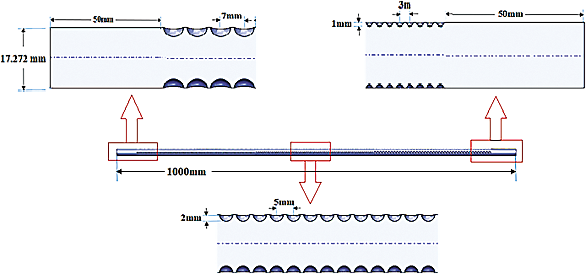
Figure 1: The characteristics of geometric models under the current study
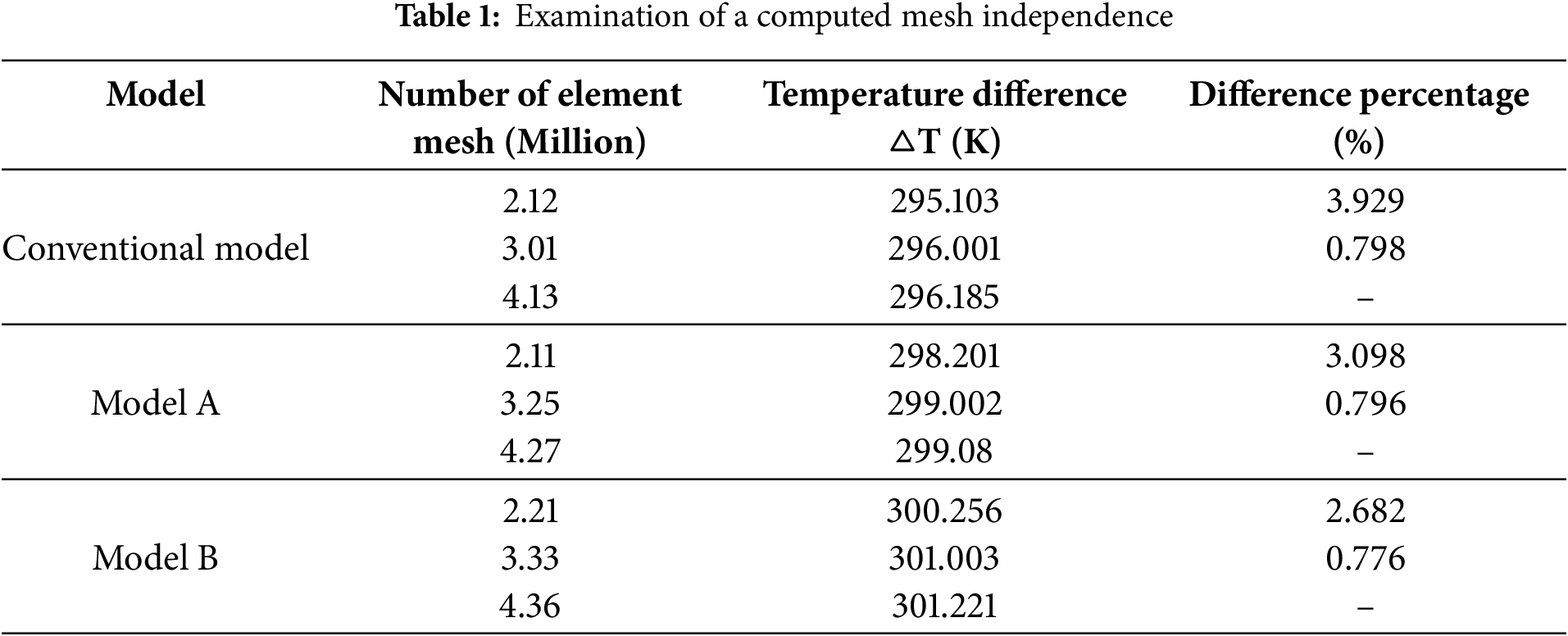
In the present investigation, tetrahedral elements are utilized in both the tube and flow domains for numerical calculations. The grid employed is designed to have a higher density near the wall, effectively capturing abrupt fluctuations in temperature and velocity (refer to Fig. 2). It appears that a smooth tube’s flow mesh domain is rather simple, with regular, distinct layers. A dimpled tube’s flow mesh domain is more complicated than a smooth tube. The dimpled tube’s mesh domain complexity is determined by several variables, including the dimples’ size, shape, and distribution. To ensure the accuracy and reliability of the computational results, grid independence tests were conducted. These tests involved using different fine grids with varying numbers of elements, that involve one, two, & three million elements. The primary examination used to evaluate the results was the temperature differential across the pipe. Based on the results displayed in Table 1, the temperature differences for the grids containing almost (3 million) elements were less than 0.8%. This suggests that additional grid improvements beyond (3 million) elements had a minimal impact on the numerical calculations. As a result, a grid with roughly three million components was selected for further investigation through numerical simulation simulations. This option allows for accurate outcomes while being computationally efficient.
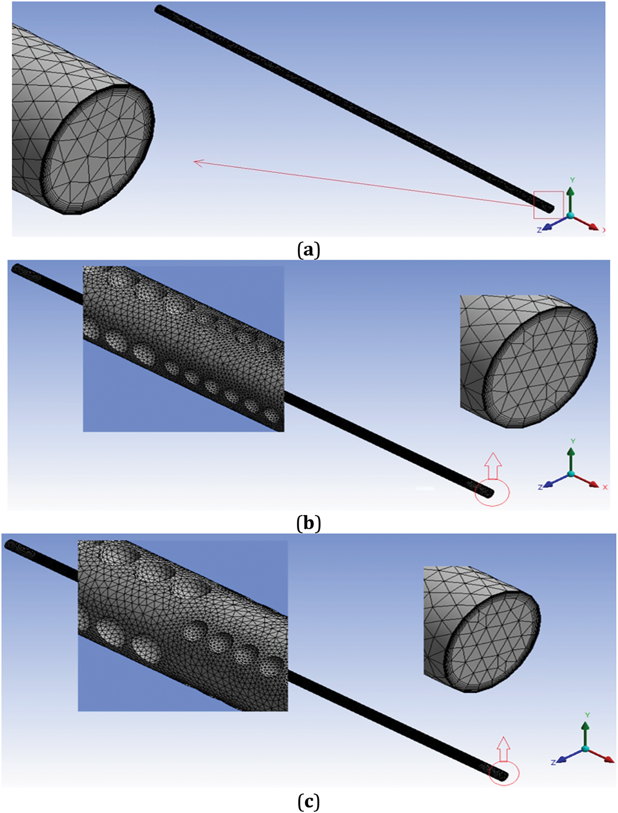
Figure 2: Mesh domain flow for (a) conventional model, (b) in-line arrangement of dimples, and (c) staggered arrangement of dimples
The turbulent flow in a heat exchanger’s pipe was examined in this study. A turbulence-characterized flow regime was indicated by the Re range that was studied, which was between 3000 and 8000. For the simulations, water was selected as a working fluid. Throughout the study, the physical properties of water were assumed to remain constant. The presumption was justified because of the heat exchanger’s limited operating temperature range, which is 300 K. In the simulations, the zero-pressure outlet boundary condition was utilized. Under these conditions, the pressure at the pipe’s exit was deemed to be equal to atmospheric pressure. Additionally, as shown in Fig. 3, a steady heat flow of 10,000 W/m2 was delivered to the dimpled tube’s exterior. This indicated that the exterior surface of the tube transported a set quantity of heat per unit area. It should be mentioned that every boundary condition used in this study was the same as one used in an earlier experimental study [25].
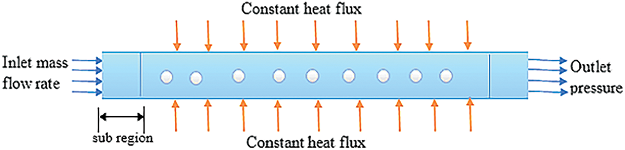
Figure 3: Boundary condition
The Reynolds-averaged Navier-Stokes (RANS) equations for steady state were employed to solve the equations of continuity, momentum, and heat transport [26].
Continuity equation:
• Momentum equation:
• Energy equation:
The Realizable k-turbulence model with enhanced wall treatment was used to simulate the turbulence in this investigation. The equations for the modeled transport of both K and ε, based on the existing model, are provided below [27].
where
The default values of the model constants have been set (
The heat transferred from the tube wall to water can be determined as follows:
where
Newton’s law for cooling can be used to calculate the coefficient heat transfer [29,30].
where
To estimate the mean bulk temperature of water, can be used the following equation:
To determine the Nu, Eq. (9) can be utilized.
where
To estimate the pressure drop within the inlet and outlet of the tube, use the formula below, which is considered among the most crucial factors for estimating hydraulic performance [31,32].
where ΔP,
Typically, the general performance criterion assesses the new proposed models’ hydro-thermal response based on the Nu and pressure drop as follows [33]. This evaluation quantifies improvements when the OPC exceeds one.
where
4.1 Validation of Numerical Model
To confirm the dependability of the numerical approach created for this research, the numerical results of the current study were compared with the experimental findings from earlier research. To construct the comparison accurately and correctly, the identical settings that were employed in the experimental investigation have been used in Ref. [9]. Fig. 4 illustrates comparing the Nu and friction factor of the fluid flow within the pipe for different Re. It is evident from this figure that is a good fit in terms of trend and difference in deviation. The greatest variation between the Nu’s numerical data is 8.5% in both the findings of the experiments and the current investigation of the earlier study (Ref. [25]). Additionally, as depicted in Fig. 4a, the largest difference between the numerical outcomes of the current investigation and the empirical correlation equation of Ref. [33] is 10.3%. The highest difference between the experimental results and the numerical data about the friction factor is 10.8%. Additionally, the greatest variation between the Ref. [34]’s equation for empirical correlation and the numerical results is 11.2%, as depicted in Fig. 4b. The differences between the present results and those referenced in Refs. [25,34,35] are likely due to errors in experimental device measurements and system thermal losses. Therefore, it is reasonable to conclude that the accepted numerical method is adequately precise and can be employed to study the impact of the parameters considered in this work, as outlined in the subsequent section.
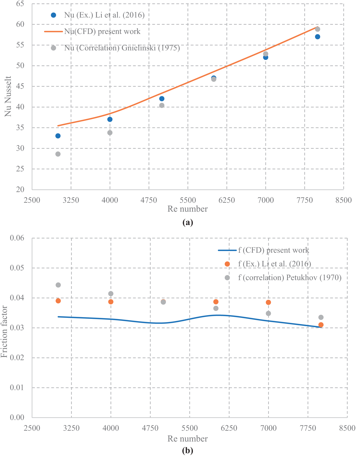
Figure 4: Demonstrates the validation of the current numerical data of the traditional model across different Re for (a) Nu and, (b) friction factor [25,34,35]
4.2 Numerical Performance Analysis
The fluid flow distribution of temperature for the three models under investigation, namely the conventional model, in-line dimpled tube, and staggered dimpled tube, is illustrated in Fig. 5. With a Re of 3000 and a starting temperature of 293 K, the fluid entering the system undergoes a heat flux of 10,000 W/m2 in the x-y plane. For all models, this figure shows that the cooling fluid temperature of the inside the tube rises in the direction of flow. The traditional smooth tube (Fig. 5a) exhibits the lowest cooling fluid temperature, while the dimpled tubes show higher temperatures due to turbulence caused by the dimples. Model -B-, with a staggered dimple arrangement, shows a greater cooling fluid temperature than Model -A- because of the dimple configuration’s improved boundary layer of heat. This evolution increases the surface area available for heat transfer, thereby enhancing the effectiveness of heat dissipation. Integrating dimples into the models fosters the evolution of thermal boundary layers and improves the mixing of the tube’s cooling fluid, resulting in increased heat transfer efficiency. The maximum cooling fluid temperatures observed in the conventional model, (Model A), and (Model B) are 295.9, 297, and 38.3 K, respectively.
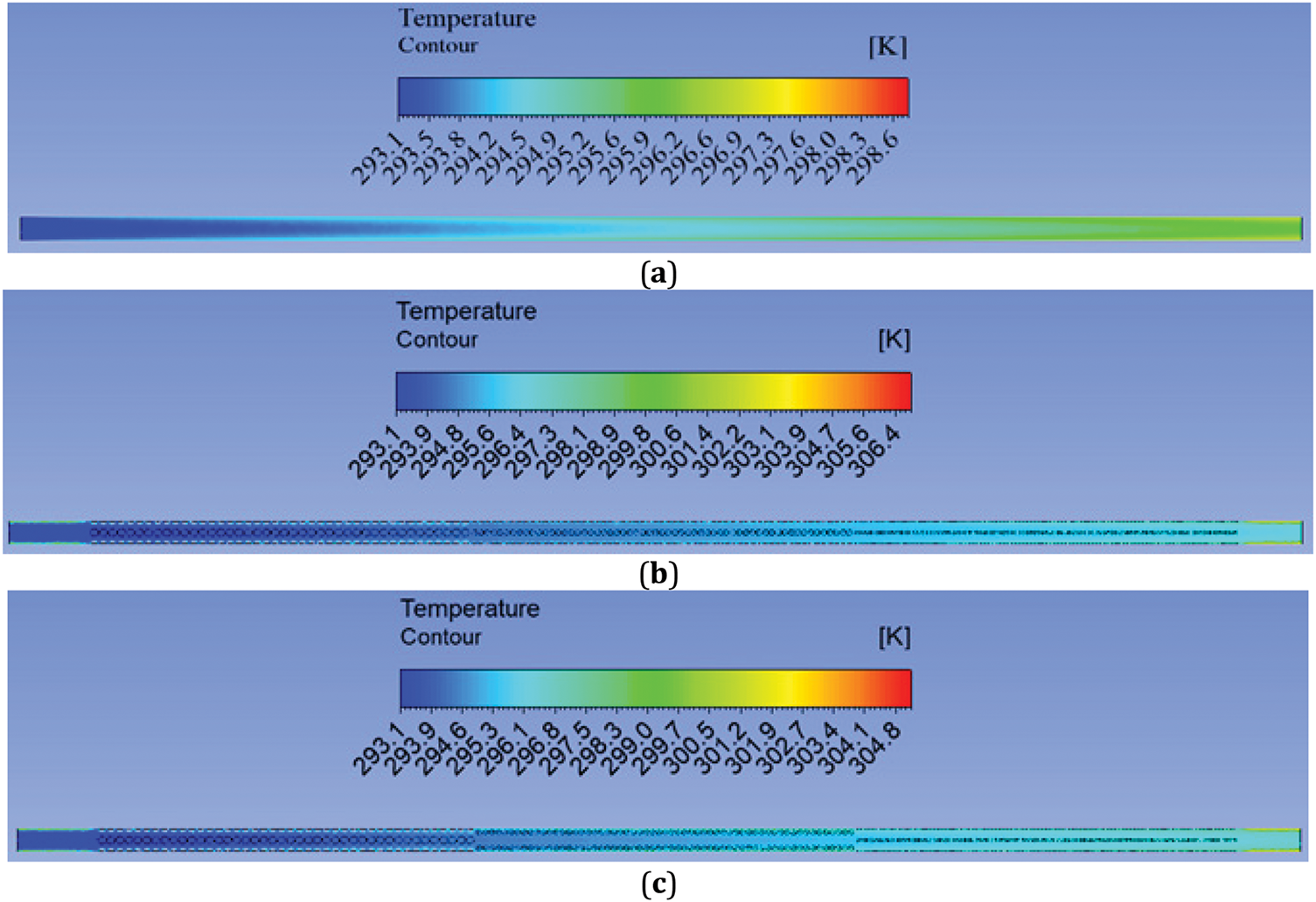
Figure 5: Counter of fluid flow temperature for (a) traditional model, (b) tube with in-line arrangement dimples and (c) staggered arrangement dimples under study at Re = 3000
Fig. 6 depicts the Nu variation for dimples arranged in-line and staggered configurations at different Re under specific boundary conditions, with heat flux at 10 kW/m2 and the inlet temperature of 20°C. This figure demonstrates that the Nu increases as the Re increases for all cases under investigation. This phenomenon happens because higher fluid velocity induces greater flow turbulence, thereby improving heat transfer, as indicated by an increase in the Nu. Furthermore, this illustration implies a remarkable improvement in heat transfer with both dimple configurations. The Nu for Model A and Model B are better than the traditional model by 43% and 35.7%, respectively. In addition, the staggered dimple arrangement (Model B) exhibits heat transfer efficacy in contrast to the in-line arrangement (Model A). This suggests a more efficient heat transfer from the pipe surface to the cooler fluid in Model B. In conclusion, the efficiency of heat transfer is modified by the staggered dimple pattern because it creates more turbulence than the in-line layout.
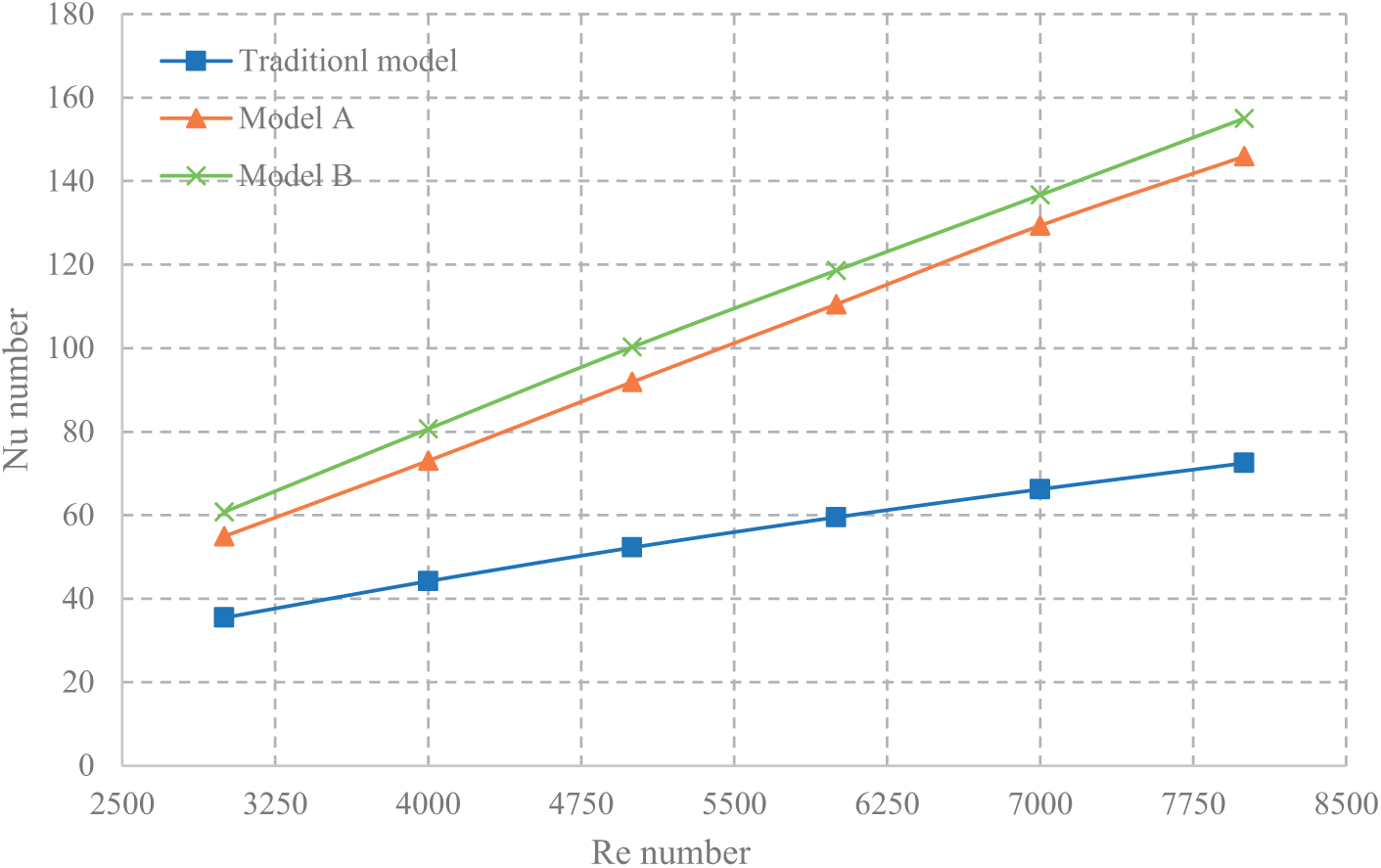
Figure 6: The impact of dimple arrangements (in-line and staggered) on average Nu across different Re
The impact of various tube configurations that consider in the current study on the average resistance for heat at varying Re within a heat flux as 10 kW/m2 at the inlet temperature of 293 K is illustrated in Fig. 7. This figure shows that the average resistance for heatdeclines with increasing flow rate. The proposed models exhibit a lower average thermal resistance in contrast to the conventional model, indicating improved performance. The use of dimples disrupts thermal boundary layers, resulting in decreased resistance for heat. At a Re of 3000, the smallest average resistance for heat is 0.00147 for Model -B- and 0.00162 for Model -A-. On the other hand, the maximum average resistance for heat of 0.00252 is displayed by the conventional model that lacks dimples. The average resistance for heat of Model -B- is significantly lower than that of the conventional model by 48%, whilst Model -A- shows a decrease of 39%.
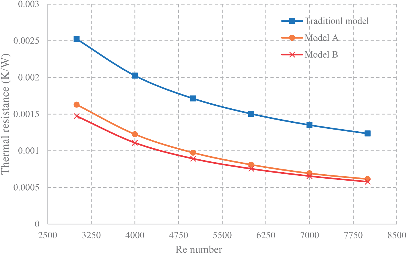
Figure 7: Distribution of the thermal resistance for all models under consideration for various Re
Fig. 8 shows the effects of various tube configurations on pressure drop at varied Re while keeping the heat flux at 10 kW/m2 and temperature of water at inlet is 293 K. The figure indicates that an increase in flow rate correlates with higher pressure drop values. Consequently, of the fluid’s interactions with the dimples on the tube surfaces, the recommended tube configurations demonstrated greater pressures. decreases than the conventional model. Since each of the suggested models had an equal number of dimples, their pressure drops were comparable. In addition, significant increases in pressure drop were seen in models A and B, with percentage increases of 58.59% and 59.13%, respectively, in comparison to the conventional model.
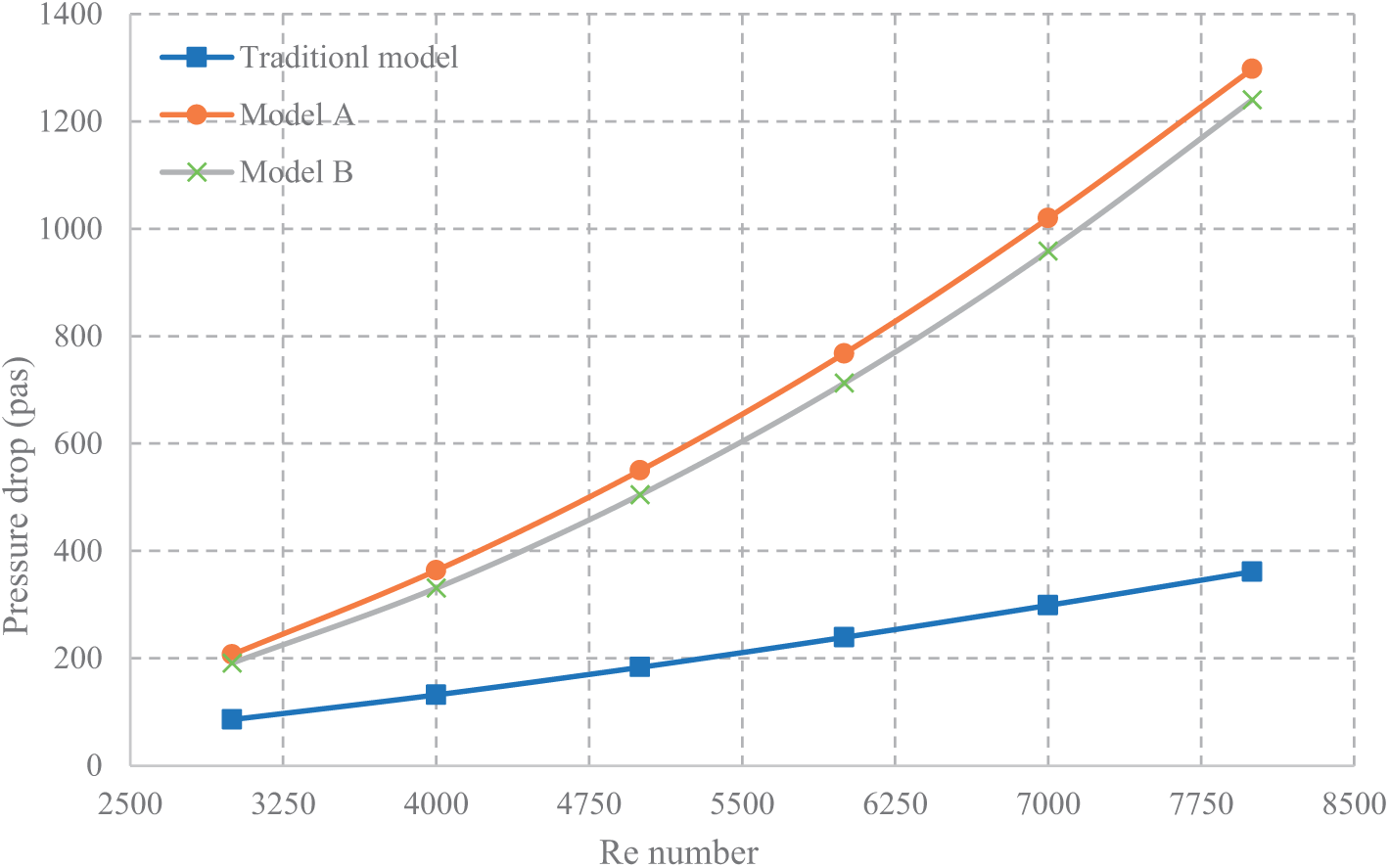
Figure 8: The pressure drop of water for all models under investigation under various Re
Fig. 9 demonstrates the outcomes of various Re on the performance of a tube with dimples at a constant heat flux of 10 kW/m2 and temperature at the inlet is 300 K. The specific placement of the dimples significantly impacted both the thermal and hydraulic behavior of tubes. To identify the most effective dimpled tube design, an extensive assessment of the performance index was conducted. The overall performance criteria of the innovative dimpled tube models exhibited a consistent increase, mostly as a result of the dimples’ disruption of the boundary layer, which raises turbulence close to the pipe’s surface. Hence, these designs led to a notable enhancement in the efficiency of heat transfer, albeit at the cost of increasing pressure drops compared to traditional tube configurations. Furthermore, both dimpled tube configurations’ overall performance criterion values are above the 1 threshold, indicating the applicability of all suggested models. Additionally, when it came to the overall performance requirements, (Model B) performed better than (Model A). The total performance requirements for (Model A and Model B) improved to (1.23 and 1.34), respectively, as Re increased.
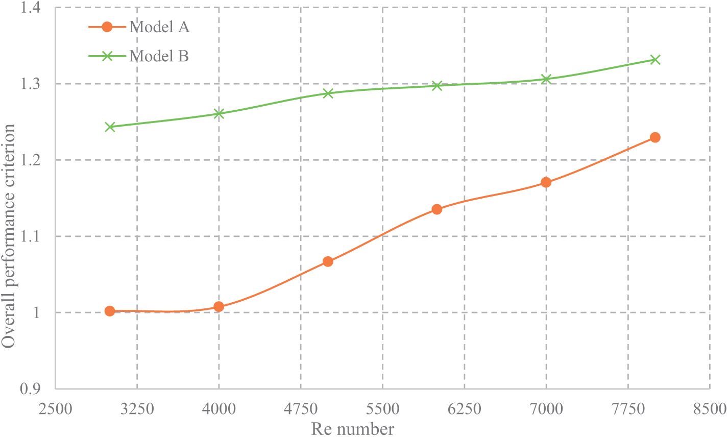
Figure 9: The overall performance criterion for new models under study for different Re
The current research shows how dimple arrangements impact various aspects of tube performance, such as flow of the fluid, heat transmission, pressure drop, thermal resistance, and overall efficiency. The accuracy of the numerical simulation for the model was confirmed by contrasting it to both prior experimental findings and correlation equations, showcasing a solid agreement with a 10% maximum departure. Several significant conclusions were drawn from this study:
1. In terms of heat transfer, the staggered dimple arrangement (Model B) surpasses the in-line structure (Model A); the Nu for (Models A and B) are, respectively, 43% and 35.7% higher than those for the standard model.
2. Compared to the conventional form, form B shows an impressive 48% reduction in thermal resistance, whilst (Model A) only manages a 39% reduction.
3. The pressure drop in (Model A) and (Model B) is significantly higher than in the conventional model, increasing by 59.13% and 58.59%, respectively.
4. The general specifications performance for both proposed models (A & B) is (1.23 and 1.34), respectively.
Acknowledgement: The authors would like to thank AL-Mustansiriyah University in Baghdad, Iraq (www.uomustansiriyah.edu.iq) for its support of this study.
Funding Statement: The authors received no specific funding for this study.
Author Contributions: The authors confirm their contribution to the paper as follows: study conception and design: Basima Salman Khalaf; data collection: Abeer H. Falih; analysis and interpretation of results: Abeer H. Falih, Basima Salman Khalaf; draft manuscript preparation: Basim Freegah. All authors reviewed the results and approved the final version of the manuscript.
Availability of Data and Materials: The data are available when requested.
Ethics Approval: Not applicable.
Conflicts of Interest: The authors declare no conflicts of interest to report regarding the present study.
Nomenclatures
| Symbol | Description Units |
| As,t | Surface area of tube m2 |
| Cpw | Water heat capacity under constant pressure KJ/kg·K |
| D | Tube diameter m |
| haw | Average water’s coefficient of heat transfer W/m2·K |
| kw | Water’s conductivity of thermal W/m·K |
| Water mass flow rate kg/s | |
| Nu | Nusslt number |
| Nut | Conventional tube Nu |
| L | Tube length m |
| f | Factor of fraction |
| ftst | Traditional tube’s Friction factor |
| P | Pressure Pa |
| Re | Reynolds number |
| Q | Heat transfer rate W |
| Ti,w | Water’s temperature at inlet K |
| To,w | Water’s temperature at outlet K |
| Tm,t | Wall mean temperature for tube K |
| Tm,w | Mean bulk temperature for water K |
| Vw | Velocity for water m/s |
| Greek Symbols | |
| Water density kg/m3 | |
| Drop of pressure N/m2 | |
References
1. Mangrulkar CK, Dhoble AS, Chamoli S, Gupta A, Gawande VB. Recent advancement in heat transfer and fluid flow characteristics in cross flow heat exchangers. Renew Sustain Energy Rev. 2019;113(10):109220. doi:10.1016/j.rser.2019.06.027. [Google Scholar] [CrossRef]
2. Mohammadi S, Mousavi Ajarostaghi SS, Pourfallah M. The latent heat recovery from boiler exhaust flue gas using shell and corrugated tube heat exchanger: a numerical study. Heat Transf. 2020;49(6):3797–815. doi:10.1002/htj.21809. [Google Scholar] [CrossRef]
3. Kaood A, Aboulmagd A, Othman H, ElDegwy A. Numerical investigation of the thermal-hydraulic characteristics of turbulent flow in conical tubes with dimples. Case Stud Therm Eng. 2022;36:102166. doi:10.1016/j.csite.2022.102166. [Google Scholar] [CrossRef]
4. Lei XS, Shuang JJ, Yang P, Liu YW. Parametric study and optimization of dimpled tubes based on Response Surface Methodology and desirability approach. Int J Heat Mass Transf. 2019;142(6):118453. doi:10.1016/j.ijheatmasstransfer.2019.118453. [Google Scholar] [CrossRef]
5. Al-Jabery FFF. Enhancement of heat exchanger performance by using dimpled tube. Alkej. 2017;13(4):41–9. doi:10.22153/kej.2017.05.002. [Google Scholar] [CrossRef]
6. Chen J, Müller-Steinhagen H, Duffy GG. Heat transfer enhancement in dimpled tubes. Appl Therm Eng. 2001;21(5):535–47. doi:10.1016/s1359-4311(00)00067-3. [Google Scholar] [CrossRef]
7. Fan Q, Yin X. 3-D numerical study on the effect of geometrical parameters on thermal behavior of dimple jacket in thin-film evaporator. Appl Therm Eng. 2008;28(14–15):1875–81. doi:10.1016/j.applthermaleng.2007.11.024. [Google Scholar] [CrossRef]
8. Li M, Khan TS, Al Hajri E, Ayub ZH. Geometric optimization for thermal-hydraulic performance of dimpled enhanced tubes for single phase flow. Appl Therm Eng. 2016;103:639–50. doi:10.1016/j.applthermaleng.2016.04.141. [Google Scholar] [CrossRef]
9. Mahmood H, Freegah B. Investigating the effect of counter flow formation, ribs and dimples on the hydrothermal performance of the serpentine Mini-Channel Heat Sink (SMCHS). Int Commun Heat Mass Transf. 2022;139(3):106490. doi:10.1016/j.icheatmasstransfer.2022.106490. [Google Scholar] [CrossRef]
10. Shafaee M, Mashouf H, Sarmadian A, Mohseni SG. Evaporation heat transfer and pressure drop characteristics of R-600a in horizontal smooth and helically dimpled tubes. Appl Therm Eng. 2016;107:28–36. doi:10.1016/j.applthermaleng.2016.06.148. [Google Scholar] [CrossRef]
11. Wang Y, He YL, Li R, Lei YG. Heat transfer and friction characteristics for turbulent flow of dimpled tubes. Chem Eng Technol. 2009;32(6):956–63. doi:10.1002/ceat.200800660. [Google Scholar] [CrossRef]
12. Wang Y, He YL, Lei YG, Zhang J. Heat transfer and hydrodynamics analysis of a novel dimpled tube. Exp Therm Fluid Sci. 2010;34(8):1273–81. doi:10.1016/j.expthermflusci.2010.05.008. [Google Scholar] [CrossRef]
13. Jiang J, Bo L, Chen Z, Cui H, Zhu H. Numerical simulation and analysis of enhanced heat transfer in corrugated tube heat exchanger. IOP Conf Ser Earth Environ Sci. 2020;467(1):012031. doi:10.1088/1755-1315/467/1/012031. [Google Scholar] [CrossRef]
14. Rahman Sardar H. Forced convection heat transfer analysis through dimpled surfaces with different arrangements. Am J Energy Eng. 2015;3(3):37. doi:10.11648/j.ajee.20150303.12. [Google Scholar] [CrossRef]
15. Antony A, Ganesan M. Flow analysis and characteristics comparison of double pipe heat exchanger using enhanced tubes. J Mech Civil Eng. 2014;7:16–21. [Google Scholar]
16. Vicente PG, García A, Viedma A. Heat transfer and pressure drop for low Reynolds turbulent flow in helically dimpled tubes. Int J Heat Mass Transf. 2002;45(3):543–53. doi:10.1016/S0017-9310(01)00170-3. [Google Scholar] [CrossRef]
17. Nazari S, Zamani M, Moshizi SA. Comparative study on the influence of depth, number and arrangement of dimples on the flow and heat transfer characteristics at turbulent flow regimes. Heat Mass Transf. 2018;54(9):2743–60. doi:10.1007/s00231-018-2307-5. [Google Scholar] [CrossRef]
18. Vignesh SV, Moorthy S, Nallakumarasamy G. Experimental and CFD analysis of concentric dimple tube heat exchanger. Int J Emerg Technol Eng Res. 2017;5(7):18–26. [Google Scholar]
19. Xie S, Liang Z, Zhang L, Wang Y, Ding H, Zhang J. Numerical investigation on heat transfer performance and flow characteristics in enhanced tube with dimples and protrusions. Int J Heat Mass Transf. 2018;122:602–13. doi:10.1016/j.ijheatmasstransfer.2018.01.106. [Google Scholar] [CrossRef]
20. Xie S, Liang Z, Zhang L, Wang Y. A numerical study on heat transfer enhancement and flow structure in enhanced tube with cross ellipsoidal dimples. Int J Heat Mass Transf. 2018;125:434–44. doi:10.1016/j.ijheatmasstransfer.2018.04.106. [Google Scholar] [CrossRef]
21. Falih AH, Khalaf BS, Freegah B. Investigate the impact of dimple size and distribution on the hydrothermal performance of dimpled heat exchanger tubes. Front Heat Mass Transf. 2024;22(2):597–613. doi:10.32604/fhmt.2024.049812. [Google Scholar] [CrossRef]
22. Rainieri S, Bozzoli F, Pagliarini G. Experimental investigation on the convective heat transfer in straight and coiled corrugated tubes for highly viscous fluids: preliminary results. Int J Heat Mass Transf. 2012;55(1–3):498–504. doi:10.1016/j.ijheatmasstransfer.2011.08.030. [Google Scholar] [CrossRef]
23. Freegah B, Khalaf BS, Falih AH. Investigate the influence of dimple distribution around the circumference of a pipe on the hydrothermal performance of dimpled tubes. Heat Transf. 2025;54(1):694–715. doi:10.1002/htj.23194. [Google Scholar] [CrossRef]
24. Mehrjardi SAA, Khademi A, Safavi SMM. Machine learning approach to balance heat transfer and pressure loss in a dimpled tube: generative adversarial networks in computational fluid dynamics. Therm Sci Eng Prog. 2025;57(10):103116. doi:10.1016/j.tsep.2024.103116. [Google Scholar] [CrossRef]
25. Li M, Khan TS, Al-Hajri E, Ayub ZH. Single phase heat transfer and pressure drop analysis of a dimpled enhanced tube. Appl Therm Eng. 2016;101:38–46. doi:10.1016/j.applthermaleng.2016.03.042. [Google Scholar] [CrossRef]
26. Wang W, Zhang Y, Li Y, Han H, Li B. Numerical study on fully-developed turbulent flow and heat transfer in inward corrugated tubes with double-objective optimization. Int J Heat Mass Transf. 2018;120:782–92. doi:10.1016/j.ijheatmasstransfer.2017.12.079. [Google Scholar] [CrossRef]
27. Fluent Ansys. 17.0 ANSYS fluent meshing user’s guide. Canonsburg, PA, USA: ANSYS Inc.; 2016. [Google Scholar]
28. Kongkaitpaiboon V, Promthaisong P, Chuwattanakul V, Wongcharee K, Eiamsa-ard S. Effects of spiral start number and depth ratio of corrugated tube on flow and heat transfer characteristics in turbulent flow region. J Mech Sci Technol. 2019;33(8):4005–12. doi:10.1007/s12206-019-0745-8. [Google Scholar] [CrossRef]
29. Wan Y, Wu R, Qi C, Duan G, Yang R. Experimental study on thermo-hydraulic performances of nanofluids flowing through a corrugated tube filled with copper foam in heat exchange systems. Chin J Chem Eng. 2018;26(12):2431–40. doi:10.1016/j.cjche.2018.07.007. [Google Scholar] [CrossRef]
30. Zhang Y, Zhou F, Kang J. Flow and heat transfer in drag-reducing polymer solution flow through the corrugated tube and circular tube. Appl Therm Eng. 2020;174(10):115185. doi:10.1016/j.applthermaleng.2020.115185. [Google Scholar] [CrossRef]
31. Córcoles JI, Belmonte JF, Molina AE, Almendros-Ibáñez JA. Influence of corrugation shape on heat transfer performance in corrugated tubes using numerical simulations. Int J Therm Sci. 2019;137:262–75. doi:10.1016/j.ijthermalsci.2018.11.021. [Google Scholar] [CrossRef]
32. Qian JY, Yang C, Chen MR, Jin ZJ. Thermohydraulic performance evaluation of multi-start spirally corrugated tubes. Int J Heat Mass Transf. 2020;156(9):119876. doi:10.1016/j.ijheatmasstransfer.2020.119876. [Google Scholar] [CrossRef]
33. Mei S, Qi C, Luo T, Zhai X, Yan Y. Effects of magnetic field on thermo-hydraulic performance of Fe3O4-water nanofluids in a corrugated tube. Int J Heat Mass Transf. 2019;128(8):24–45. doi:10.1016/j.ijheatmasstransfer.2018.08.071. [Google Scholar] [CrossRef]
34. Gnielinski V. New equations for heat and mass transfer in turbulent pipe and channels. Int Chem Eng. 1975;16(2):359–67. [Google Scholar]
35. Petukhov BS. Heat transfer and friction in turbulent pipe flow with variable physical properties. Adv Heat Transfer. 1970;6(2):503–64. doi:10.1016/s0065-2717(08)70153-9. [Google Scholar] [CrossRef]
Cite This Article
 Copyright © 2025 The Author(s). Published by Tech Science Press.
This work is licensed under a Creative Commons Attribution 4.0 International License , which permits unrestricted use, distribution, and reproduction in any medium, provided the original work is properly cited.
 Downloads
 Citation Tools