
 Submit a Paper
 Propose a Special lssue
 Open Access
ARTICLE
Numerical Simulation and Experimental Study of Self-Supplied Aerostatic Air Float Piston in Miniature Linear Compressor
1 Nantong Yangtze River Delta Institute of Intelligent Sensing, Nantong, 226009, China
2 Institute of Refrigeration and Cryogenics, Zhejiang University, Hangzhou, 310058, China
* Corresponding Authors: Haifeng Zhu. Email: ; Zhenyu Chen. Email:
Frontiers in Heat and Mass Transfer 2025, 23(4), 1303-1321. https://doi.org/10.32604/fhmt.2025.065830
Received 22 March 2025; Accepted 11 June 2025; Issue published 29 August 2025
 View Full Text
 Download PDF
Abstract
To meet the demand for miniaturized, compact, high-reliability, and long-life cryocoolers in small satellite platforms, the development of a linear Stirling cryocooler has been undertaken. Computational Fluid Dynamics (CFD) numerical simulation software was used to conduct simulation analyses, verifying the impact of porous media channel layout, eccentricity, viscous resistance coefficient of the porous media, and piston position on the designed aerostatic bearing piston employing self-supplied gas bearing technology. The calculation results indicate that both the aerostatic force and leakage increase synchronously with eccentricity, while the two designed gas lift channel layouts are capable of providing sufficient load-bearing capacity while ensuring minimal leakage. Through calculations, it was determined that the viscous resistance coefficient of the porous media material, used as a throttling mechanism, is most suitable within the range of 8 × 10¹¹ to 8 × 10¹³ 1/m2. When studying the piston position, it was found that due to the influence of the gas film length, the aerostatic force gradually increases as the piston moves from the maximum compression stroke state to the maximum low-pressure stroke state. To validate combining simulation with experimental platform testing, a support fixture platform for testing the load-bearing capacity of the gas bearings was independently constructed. The development of the aerostatic bearing piston prototype was completed, and performance tests were conducted, confirming that the trend of aerostatic force variation with gas film length is consistent with calculations. Additionally, it was verified that under the two aerostatic channel layouts, the aerostatic force closely matches the calculated values.Keywords
With the development of commercial aerospace and the mature application of small satellite platforms such as CubeSats, there is an increasing demand for miniaturized payloads [1–3]. Current high-reliability, long-life aerospace linear Stirling cryocoolers rely on flexure spring support and clearance sealing [4,5] to achieve wear-free operation. However, as miniaturization progresses, the design and manufacturing complexity of flexure springs increases significantly. Replacing traditional flexure springs with hydrostatic gas bearings has emerged as an effective technical solution to enable long-life operation in micro-scale linear Stirling cryocoolers [6–10].
In the field of Stirling cryocoolers, gas-bearing compressors have been widely adopted [11]. To meet the requirements of long-life cryocoolers, Zhu et al. [12] developed a pulse tube cryocooler using an aerostatic bearing compressor. Zhou et al. [13] investigated the impact of regenerator packing on the performance of gas-bearing com-pressor-driven pulse tube cryocoolers. At a high operating frequency of 52 Hz, the cryocooler achieved a no-load temperature of 19.4 K and a cooling capacity of 0.937 W at 30 K. The compressor weight was reduced to 3.5 kg, only one-third of conventional spring-supported linear compressors, demonstrating the critical role of gas bearings in weight reduction and lifespan enhancement. However, the self-supplied gas bearings rely on high-pressure gas supplied by the linear compressor. Gas consumption from the aerostatic support system reduces refrigeration efficiency, with mechanical power losses typically below 5% in conventional systems [14]. As compressors shrink in size, reduced piston swept volumes amplify the proportion of gas consumption losses relative to useful compression work. This necessitates precise optimization of aerostatic flow channels to maximize bearing forces while minimizing gas consumption, balancing performance and efficiency [15–18].
Key performance metrics of aerostatic bearing pistons, such as load capacity and gas leakage, are challenging to measure directly during operation. Computational Fluid Dynamics (CFD) tools are therefore essential for numerical analysis of gas bearing performance to guide structural and parametric design. Simulations often reveal generalized design principles for specific configurations. For example, Zhang et al. [19] at Huazhong University of Science and Technology used CFD to analyze how geometric parameters and inlet/outlet pressures affect gas bearing load capacity and mass flow, identifying configurations that maximize stiffness while minimizing pumping losses. Qian et al. [20] simulated the effects of eccentricity, orifice diameter, and gas film thickness on radial load capacity and gas consumption using FLUENT, deriving optimal orifice diameters for varying film thicknesses. Zhu et al. [21] optimized frictionless cylinder dimensions via MATLAB simulations in high-precision load systems, while Liu et al. [22] employed particle swarm optimization (PSO) algorithms to refine frictionless cylinder designs and developed pneumatic gravity compensation systems for motion control [23,24].
Previous studies on gas bearings often simplified flow field models using symmetry or mapping techniques to analyze single-channel configurations. However, practical designs require multiple aerostatic channels to enhance leakage tolerance, improve load uniformity, and increase overall bearing capacity. Given the significant scale difference between piston dimensions and individual channels, and the varying pressure environments across channels during piston motion, extrapolating single-channel behavior to full-scale systems is inadequate. Comprehensive studies on complete aerostatic bearing piston-cylinder structures are essential, followed by experimental validation.
This paper proposes, designs, and develops a self-supplied hydrostatic aerostatic bearing piston. Compressors utilizing this technology offer advantages including compact size, lightweight construction, extended lifespan, low vibration, and high reliability. A 3D full-scale CFD model was established under realistic compressor pressure conditions to investigate gas film pressure distribution, leakage characteristics, and aerostatic force trends. Key variables include porous media channel layout, eccentricity, viscous resistance coefficients, and piston position. A dedicated test platform was constructed to validate the aerostatic force response to these parameters, ensuring robust design validation.
2 Numerical Simulation of the Aerostatic Bearing Piston
2.1 Model Structural Parameters
The schematic diagram of a typical gas bearing in a linear compressor is shown in Fig. 1. During the piston compression process, high-pressure gas enters the reservoir chamber through the check valve inside the piston. The pressure in the reservoir chamber remains consistently high. The high-pressure gas flows through the orifice and forms a gas film with certain stiffness in the radial clearance between the aerostatic bearing piston and cylinder, which serves to support and lubricate the reciprocating motion of the piston. The aerostatic bearing piston structure in this study is based on the development of a compact coaxial miniature Stirling cryocooler. The compressor features an opposed-piston configuration, with a piston diameter of 9 mm and a maximum stroke of 3 mm. The piston employs a fully gas-bearing support technology to achieve wear-free operation. The main body of the piston is constructed from high-strength SS316 material. Fig. 2 illustrates the arrangement of the porous media channels that support the piston. The porous media, serving as aerostatic orifices, are made of high-porosity titanium powder sintered material. Its throttling characteristics help reduce the leakage of high-pressure gas from the volume into the gas film, ensuring sufficient lift for the gas-bearing piston while minimizing the pressure drop in the gas reservoir caused by the gas-bearing structure. Addi-tionally, it filters out dust and impurities generated during compressor operation, preventing blockages between the cylinder wall and the piston due to the presence of particulate matter in the gas film. Each piston consists of two rows of six or eight porous media channels, each with a diameter of 1 mm, connected to the gas film through a bell-shaped pressure equalization structure.

Figure 1: Schematic Diagram of the Aerostatic Bearing Piston. (a) Schematic Diagram of a Typical Aerostatic Bearing Piston; (b) Piston Internal Structure Diagram

Figure 2: Schematic diagram of different orifice layout configurations. (a) 2 × 4 aerostatic channel layout; (b) 2 × 3 aerostatic channel layout
The working mechanism of the gas bearing is as follows: As shown in Fig. 1, the compressor primarily consists of three chambers: the compression chamber, the gas reservoir chamber, and the backpressure chamber. The gas reservoir chamber maintains high pressure through a check valve. When the pressure in the compression chamber exceeds that of the gas reservoir chamber, the check valve opens to allow gas to enter the gas reservoir chamber. When the compression pressure decreases, the check valve closes to prevent gas from flowing out of the gas reservoir chamber. As the piston moves, the volume of the compression chamber changes periodically, and the pressure difference between the gas reservoir chamber and the compression chamber controls the operation of the check valve. During the exhaust cycle, the pressure in the gas reservoir chamber decreases until the check valve opens, balancing the pressure. Subsequently, the pressure in the gas reservoir chamber rises with the increasing pressure in the compression chamber until it reaches a peak and begins to decline, at which point the check valve closes, and the cycle repeats.
Since the pressure in the gas reservoir chamber is always higher than that in the compression chamber or the backpressure chamber, the gas flow direction in the porous media channels is always from the gas reservoir chamber toward the gas film. Due to gravity, the piston tends to tilt toward the lower side of the cylinder wall, resulting in a thinner gas film at the lower side and a thicker gas film at the upper side. This causes an increase in flow resistance at the lower gap and a decrease at the upper gap, creating a pressure difference between the upper and lower surfaces of the piston. This pressure difference generates a supporting force opposite to the eccentric direction of the piston, lifting it completely off the cylinder wall and thereby reducing friction.
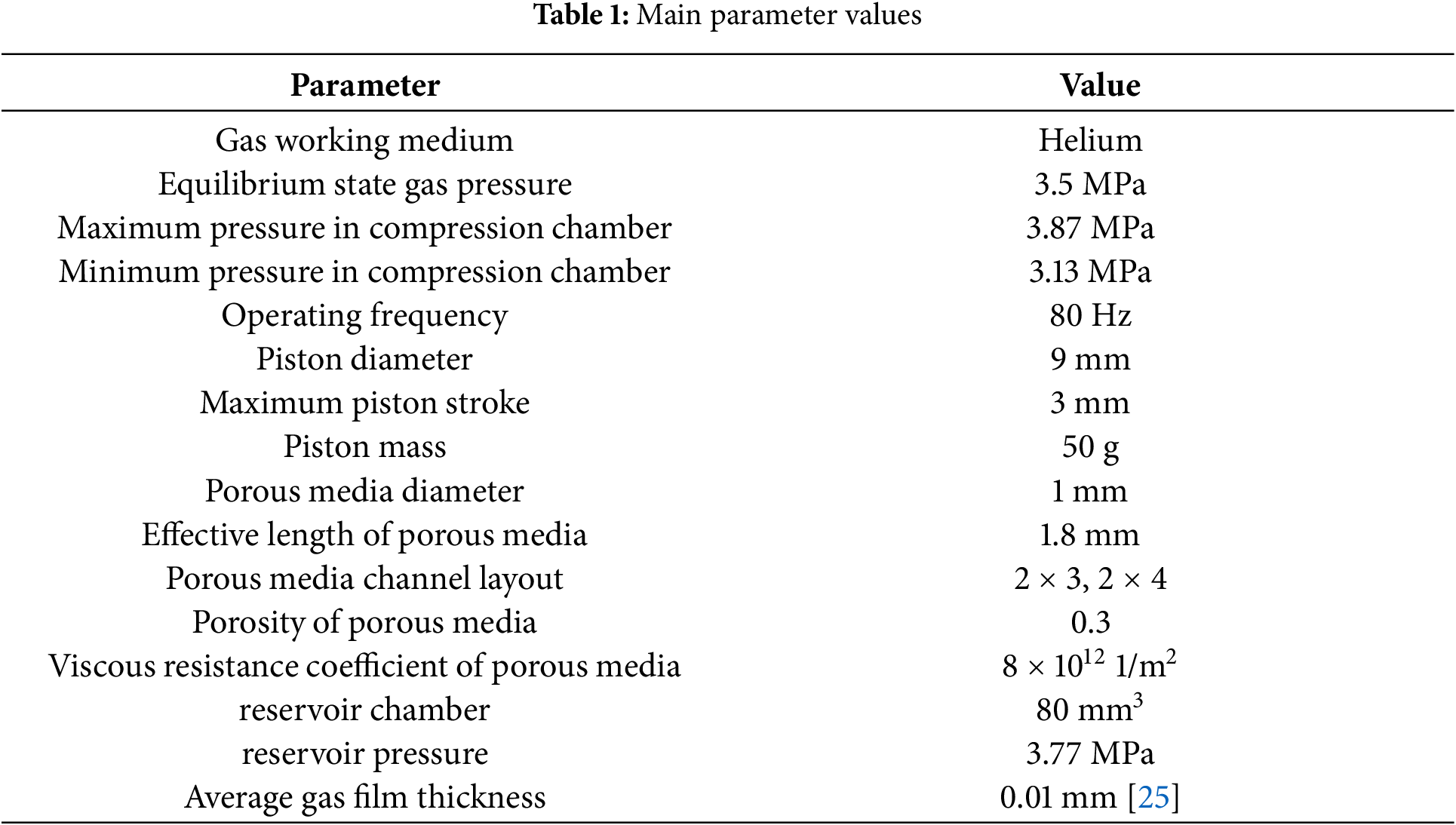
Using CFD simulation, the relationship between flow rate and aerostatic force was calculated for the piston at three different states: the two extreme stroke positions and the equilibrium position. The results verify that a sufficiently large aerostatic force to support the piston’s weight can be generated with minimal gas leakage through the porous media channels. The main calculation parameters are listed in Table 1. The designed opening pressure difference of the check valve is 0.1 MPa. Due to the small gas leakage in the porous media channels, the gas reservoir chamber pressure is assumed to be a constant value of 3.77 MPa for simplicity. Two different aerostatic configurations are shown in Fig. 2. In the configuration with 2 × 3 layout, the orifices are staggered to prevent uneven circumferential distribution caused by installation angles.
The layout of porous media channels significantly affects the pressure distribution within the gas film, while the total cross-sectional area of these channels directly influences the magnitude of the aerostatic force and gas leakage. The eccentricity of the piston is a critical factor in determining the aerostatic force. When the eccentricity reaches 1, indicating that the maximum aerostatic force is insufficient to support the piston, friction between the piston and the cylinder wall will occur. This not only disrupts the boundary lubrication but can also severely damage the piston, a situation that must be avoided. In addition to eccentricity, the aerostatic force and gas leakage are influenced by several other factors, with the viscous resistance coefficient of the porous media and the piston’s stroke position being particularly significant. These factors must be carefully considered to optimize the performance and reliability of the gas-bearing-supported piston system.
All models in this study utilize structured grids. The 2 × 3 configuration model contains approximately 2,790,000 grid cells, while the 2 × 4 configuration model has about 2,850,000 grid cells. Special grid refinement was applied in the gas film thickness direction. On one hand, denser grids in this direction can more accurately capture the gas flow behavior across the film thickness. On the other hand, excessive grid density significantly increases the total grid count and reduces computational speed. After optimization, 8 grid layers were ultimately selected in the gas film thickness direction. The numerical simulations employ a steady-state calculation method. Pressure-velocity coupling use coupled scheme. Viscous model use standard k-epsilon turbulence model. Convergence criteria is all residuals (continuity equation and velocity components in X, Y, Z directions) must decrease below 10−3.
In the flow field of the aerostatic piston, different regions exhibit distinct flow types. The gas film is dominated by convection, while diffusion prevails in the porous media where the fluid velocity is very low.
The mass conservation equation or continuity equation in porous media can be expressed as follows:
where ε is the porosity of the porous media. Porosity refers to the ratio of void space to the total volume of the porous media. Higher porosity leads to greater molecular passage rate. This equation is valid for both incompressible and compressible flows. In porous media, the porosity is not equal to 1 and depends on actual material properties, while in the gas film, the porosity equals 1. Sm represents the mass source term, which is 0 in this model as there is no mass generation or loss.
Mass transport in porous media occurs through three mechanisms: Knudsen diffusion, molecular diffusion, and viscous flow. Knudsen diffusion refers to the diffusion where the pore size of the porous media is smaller than the mean free path of particles, and the diffusion resistance mainly comes from the walls of the porous media. The Dusty Gas model incorporates all three transport mechanisms by treating the porous media as part of the gas, combining Knudsen diffusion and molecular diffusion based on the Stefan-Maxwell framework:
where Di, k is the Knudsen diffusion coefficient of component i in the porous media.
The momentum conservation equation in porous media channels is:
where Su is the mass source term and equals 0. Since the effective thickness of the porousmedia is onlyorous media is only 1.8 mm, the gas velocity gradient in the porous media is significant, and both viscous forces and flow inertia have notable effects. Darcy’s law is typically used to describe the momentum:
where B0 is the permeability of the porous media, and φg is the porosity [26,27].
2.2 The Pressure Distribution under Different Porous Media Channel Layouts
The piston operates under three distinct states: the maximum stroke compression position, the maximum stroke low-pressure position, and the equilibrium position. The corresponding pressures in the compression chamber for these states are 3.5, 3.13, and 3.87 MPa, respectively. Steady-state calculations were performed for both the 2 × 3 and 2 × 4 porous media channel layouts using a flow field structure identical to the actual dimensions.
Fig. 3 shows the pressure distribution of the piston with a 2 × 3 porous media layout at an eccentricity of 0.4 under different compression chamber pressures. It can be observed that the pressure in the gas film varies uniformly between the compression chamber and the backpressure chamber, with this trend being minimally affected by the porous media channels. Regardless of the compression chamber pressure, the pressure inside the porous media channels (i.e., the gas reservoir pressure) remains higher than the pressure in the corresponding pressure-equalizing structures. This indicates that, under the condition of stable gas reservoir pressure, the working medium always flows from the gas reservoir to the gas film, ensuring that a force opposing the eccentric direction acts on the piston throughout the entire cycle. This demonstrates a centering tendency in the aerostatic structure.

Figure 3: Pressure distribution of the system under different compression chamber pressures for the 2 × 3 layout. (a) Gas film pressure distribution at maximum compression chamber pressure; (b) Porous media channel pressure distribution at maximum compression chamber pressure; (c) Gas film pressure distribution when compression chamber pressure equals backpressure chamber pressure; (d) Porous media channel pressure distribution when compression chamber pressure equals backpressure chamber pressure; (e) Gas film pressure distribution at minimum compression chamber pressure; (f) Porous media channel pressure distribution at minimum compression chamber pressure
In Fig. 3a,b, the maximum pressure occurs in the compression chamber, while the minimum pressure is in the backpressure chamber, with a pressure difference of 0.37 MPa. After passing through the porous media channels near the compression and backpressure chambers, the gas reservoir pressure drops to approximately 3.64 and 3.55 MPa, respectively. The flow rate between the gas reservoir and the compression/backpressure chambers is very small. The flow velocity in the gas film is primarily from the compression chamber to the backpressure chamber, with higher velocity at the upper part and lower velocity at the lower part, generating a small lifting force. However, this force is much smaller than the direct force from the gas reservoir acting on the cylinder. Thus, the aerostatic force is minimal in this scenario.
In Fig. 3c,d, the pressures in the compression chamber and backpressure chamber are equal. The working medium flows from the gas reservoir to both the compression and backpressure chambers. The pressure in the gas film is relatively uniform, while a significant pressure gradient exists at the porous media due to the throttling effect of the fine, tortuous pores. This results in a sharp increase in flow resistance through the porous media, causing a large pressure drop in this region. After passing through the porous media channels near the compression and backpressure chambers, the gas reservoir pressure drops to nearly the same level as the compression and backpressure chambers. Since the pressures in the compression and backpressure chambers are equal, there is no relative flow. In this case, the flow velocity in the gas film is primarily driven by the gas reservoir’s sweeping flow.
In Fig. 3e,f, the gas reservoir remains at the maximum pressure, while the compression chamber pressure drops to the minimum. The working medium flow is divided into three parts: flow from the gas reservoir to the compression chamber through the channels near the compression chamber, flow from the gas reservoir to the backpressure chamber through the channels near the backpressure chamber, and flow from the backpressure chamber to the compression chamber through the gas film. Due to the throttling effect of the porous media, the gas reservoir pressure drops to approximately 3.35 and 3.6 MPa near the compression and backpressure chambers, respectively. This results in a pressure difference of 0.1 MPa between the gas reservoir and the backpressure chamber after throttling, and a pressure difference of 0.2 MPa between the gas reservoir and the compression chamber. In this scenario, the gas reservoir simultaneously supplies gas to both the compression and backpressure chambers. The non-uniform gas film generates an upward aerostatic force, while the 0.37 MPa pressure difference between the compression and backpressure chambers creates a smaller lifting force due to higher flow velocity at the upper part of the gas film. The combined effect of these two forces results in the maximum aerostatic force in this state. Among the three operating conditions, the aerostatic force is smallest when the compression chamber pressure is highest and largest when the compression chamber pressure is lowest.
From the above analysis, it is evident that the aerostatic force in the piston is composed of two parts: the force generated by the sweeping gas from the throttling orifices due to the eccentricity of the gas film, and the force resulting from the direct gas flow between the compression and backpressure chambers, which creates a pressure difference across the gas film due to eccentricity. While both components contribute to the aerostatic force, the influence of the sweeping gas from the throttling orifices is more significant. Additionally, the assumption of a constant gas reservoir pressure highlights the positive impact of maintaining high gas reservoir pressure on increasing the aerostatic force. Therefore, in practical applications, it is essential to maximize the volume of the gas reservoir to minimize the impact of gas discharge on its pressure.
Fig. 4 shows the pressure distribution of the system under different compression chamber pressures for the piston with a 2 × 4 porous media layout at an eccentricity of 0.4. Compared to Fig. 3, it can be observed that although the number of porous media channels has increased, leading to a corresponding increase in the flow rate through the porous media, the pressure distribution in the gas film remains almost identical to that of the 2 × 3 layout. This further demonstrates that the porous media channels have no significant impact on the pressure distribution in the gas film. By comparing the pressure distribution within the porous media channels under the same pressure conditions for both the 2 × 4 and 2 × 3 layouts, it is evident that since the gas reservoir pressure is consistent and the pressure distribution in the aerostatic channels is nearly identical, a limited increase in the number of aerostatic channels does not affect the pressure at the outlet of these channels. This suggests that, under the same pressure conditions, the flow rate within the porous media channels is not influenced by their layout configuration. Maintaining a low flow rate within the porous media channels is also beneficial for preserving the high pressure in the gas reservoir.

Figure 4: Pressure distribution of the system under different compression chamber pressures for the 2 × 4 layout. (a) Gas film pressure distribution at maximum compression chamber pressure; (b) Porous media channel pressure distribution at maximum compression chamber pressure; (c) Gas film pressure distribution when compression chamber pressure equals backpressure chamber pressure; (d) Porous media channel pressure distribution when compression chamber pressure equals backpressure chamber pressure; (e) Gas film pressure distribution at minimum compression chamber pressure; (f) Porous media channel pressure distribution at minimum compression chamber pressure
The following Fig. 5 shows the pressure distribution on the radial cross-section of the porous medium under 2 × 3 and 2 × 4 layout when eccentricity is 0.4, pressure of compression chamber is 3.5 Mpa. When the pressure scale is reduced to 3.65–3.77 MPa, it can be clearly observed that due to the eccentric effect of the gas film, there exists a maximum pressure difference of approximately 0.06 MPa between the upper and lower parts of the gas film. The actual aerostatic force is calculated through circumferential integration over the upper and lower halves of the gas film. Additionally, the piston designed in this study weighs only 50 g, requiring relatively small bearing capacity.

Figure 5: Pressure distribution on the radial cross-section of the porous medium under 2 × 3 and 2 × 4 layout when eccentricity is 0.4, pressure of compression chamber is 3.5 MPa. (a) 2 × 3 layout; (b) 2 × 4 layout
2.3 The Influence of Eccentricity
As mentioned above, excessive gas leakage through the porous media channels can affect the maintenance of high pressure in the gas reservoir, while larger gas leakage can generate greater aerostatic force. Therefore, it is necessary to determine a reasonable balance between gas leakage and load capacity. As shown in Fig. 6, the influence of different compression chamber pressures on the load capacity of the aerostatic bearing piston is illustrated for the 2 × 3 and 2 × 4 layouts at eccentricities of 0.4, 0.6, and 0.8. It can be observed that, under the same compression chamber pressure, the aerostatic force changes linearly with eccentricity. Moreover, the rate of change is similar across different layouts and compression chamber pressures, with a rate of approximately 0.49 in this structure. At the same eccentricity, the higher the compression chamber pressure, the greater the aerostatic force. For example, at an eccentricity of 0.6, a pressure increase of 0.37 MPa results in an approximately 15.2% increase in load capacity. Both porous media channel layouts (2 × 3 and 2 × 4) ensure that the load capacity exceeds the piston’s weight of 0.5 N throughout the entire cycle.
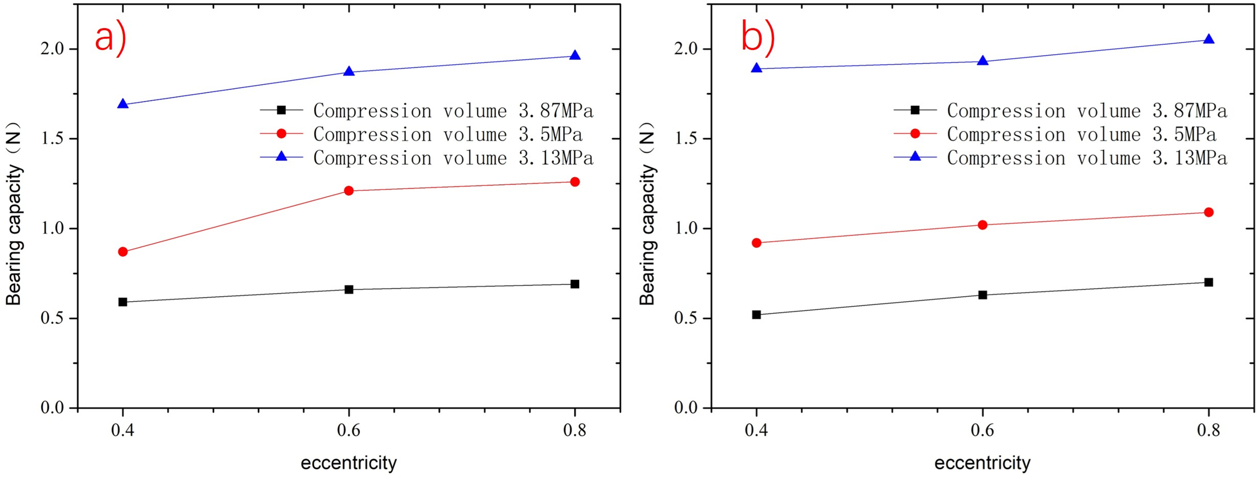
Figure 6: Variation of bearing capacity with eccentricity under different compression chamber pressures for the two layouts. (a) 2 × 3 layout; (b) 2 × 4 layout
Fig. 7 shows the variation in gas leakage for the two porous media channel layouts. It can be observed that the gas leakage in the 2 × 4 layout is greater than that in the 2 × 3 layout, which is caused by the larger leakage area in the 2 × 4 configuration. Additionally, under the same layout, changes in eccentricity have minimal impact on gas leakage. Therefore, when the dimensions of the cylinder wall and piston are fixed, the gas leakage in the porous media channels does not vary significantly with changes in the piston’s position within the cylinder. This approximately constant value allows for a relatively accurate calculation of the pressure loss caused by aerostatic support in the actual compressor.

Figure 7: Variation of gas leakage with eccentricity for the two layout configurations
Excessive gas leakage can affect the actual performance of the cryocooler. Based on a piston movement of 3 mm, the maximum swept volume of the piston is 0.236 mL. For the 2 × 3 layout, the periodic gas leakage accounts for 4.7% of the maximum swept volume, while for the 2 × 4 layout, it accounts for 5.9%. The minor leakage during discharge results in negligible plenum pressure variation, justifying its treatment as a constant value in analysis. This also proves the rationality that the gas pressure in the Reservoir chamber is assumed to be 0.1 MPa.
2.4 Influence of Viscous Resistance Coefficient of Porous Media
The gas leakage flow from the plenum to the gas film increases as the viscous resistance coefficient of the porous media decreases. Our design specification limits this leakage flow to no more than 6% of the swept volume at a 3 mm stroke. An insufficient viscous resistance coefficient would cause the leakage to exceed this design constraint. Conversely, increasing the viscous resistance coefficient reduces leakage flow, but simultaneously decreases the aerostatic force. This reduction may result in inadequate force to maintain proper piston support. Therefore, the porous media’s viscous resistance coefficient must be optimized within a specific operational window to achieve both controlled leakage flow (≤6% of swept volume) and sufficient load-bearing capacity
The viscous resistance coefficient of porous medium is the main factor affecting the flow characteristics of working medium in porous medium. The viscous resistance coefficient of 8 × 10¹² 1/m2 used in the above calculation is the value of common titanium powder sintered porous media. However, the viscous resistance coefficient of different materials and different processes will affect the air buoyancy and deflating amount. Too small air buoyancy and too large deflating amount are not conducive to the stable operation of the aerostatic bearing piston. Therefore, the influence of the viscous resistance coefficient of porous medium on the air buoyancy and deflating amount is studied in order to select the value suitable for the actual working state of the compressor. Due to the material change has a great influence on the viscous resistance coefficient of porous media, the viscous resistance coefficient of porous media is changed exponentially. The gas film eccentricity is 0.6 and the deflating amount is the deflating amount during the piston movement.
It can be seen from Figs. 8 and 9 that with the increase of the viscous resistance of the porous medium, the viscous resistance of the working medium flowing in the porous medium is enhanced, and the flow rate through each porous medium channel is reduced, thus reducing the air buoyancy. As can be seen from the Fig. 9, when the viscous resistance of the porous medium is greater than 8 × 10¹¹, the air buoyancy and deflating amount increase sharply, while when the viscous resistance of the porous medium is less than 8 × 10¹³, the deflating amount and gas buoyancy change little. Therefore, it can be judged that the viscous resistance of porous media between 8 × 10¹¹ and 8 × 10¹³ is a more appropriate value.
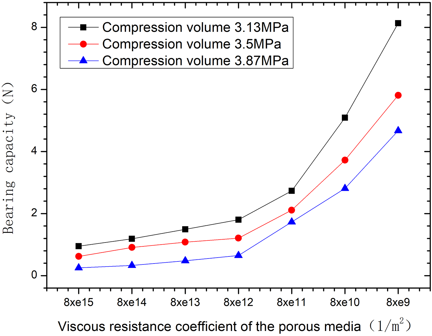
Figure 8: Variation of gas buoyancy with viscous resistance coefficient of porous medium under different compression chamber pressure

Figure 9: Change of deflating amount with viscous resistance coefficient of porous medium
2.5 Influence of Piston Position
In order to more accurately show the flow of the aerostatic hole at different positions during the piston movement cycle, as shown in Fig. 10, the black straight line represents the cylinder wall, and the blue shape represents the piston. The gas film length corresponds to the length of the narrow gap formed between the cylinder wall and piston. Since the cylinder wall remains stationary while the piston undergoes reciprocating motion, the length of this gap varies dynamically—that is, the gas film length changes accordingly. Three typical positions are selected during the piston movement cycle, namely, maximum stroke compression state, balance state and maximum stroke low pressure state, among which the maximum stroke is 3 mm. More refined, the piston position is taken −3, −2, −1, 0, 1, 2, 3 mm to show the piston motion state.

Figure 10: Simulation of the typical positions of the three pistons and their positions in the cylinder. (a) Maximum stroke compression state; (b) Equilibrium state; (c) Maximum stroke low pressure state
The position of the piston mainly affects the length of the gas film. When the piston is in the state of maximum stroke compression, the length of the gas film is the longest, which is +3 mm in this model; when the piston is in the state of maximum stroke low pressure, the length of the gas film is the shortest, which is −3 mm in this model. The change of the position of the piston does not affect the distance between the porous medium channel and the compression chamber. The increase of the gas film length is reflected in the distance between the porous medium channel and the back pressure chamber, which affects the pressure distribution around the air flotation channel and causes the change of the air buoyancy.
CFD calculation of the above model is carried out to study the variation trend of air buoyancy and deflating amount with piston position under different pressure of Reservoir chamber. In order to facilitate test verification, in this model, the working medium is nitrogen, the compression chamber and the back pressure chamber are all atmospheric pressure, the pressure of the Reservoir chamber is 1 bar, 2 bar, 3 bar, 4 bar and 5 bar, respectively, and the eccentricity of the gas film is 0.6.
Fig. 11 shows the variation trend of air buoyancy with piston position under different pressure of Reservoir chamber. The pressure of Reservoir chamber increases evenly, and the increase amplitude of air buoyancy is also relatively uniform. Under the same pressure of the air storage chamber, the piston moves from the maximum stroke compression state to the maximum stroke low pressure state, and the air buoyancy increases gradually.

Figure 11: Variation of air buoyancy with piston position under different pressure of air storage chamber
3 Static Performance Test and Result Analysis of Pneumatic Piston
Because the aerostatic bearing piston is loaded in the compressor, its motion state cannot be measured, and the air buoyancy force generated by the aerostatic bearing piston structure during operation cannot be judged. In order to obtain the air buoyancy of the aerostatic bearing piston under the given pressure difference, the aerostatic bearing capacity test was carried out through the designed test piston structure, and the bearing capacity test was used to verify the fluid calculation method and predict the specific force of the aerostatic bearing piston in the compressor. Our unit has built the support fixture platform for the bearing capacity test of the aerostatic bearing to carry out the test, and the test platform is shown in Fig. 12a. The test platform is mainly composed of the main engine box, Y-axis linear module and rotating table, X-axis module, force application and measuring mechanism, and tablet computer. By applying driving force to the cylinder supported by the aerostatic bearing, the test fixture monitors the contact between the cylinder and the piston body and measures the supporting force of the aerostatic bearing under the given air supply pressure of the aerostatic bearing chamber. The driving mechanism is used to adjust the different relative positions of the air float piston and cylinder in the circular direction and axial direction, and test the supporting force of aerostatic bearing, aerostatic bearing consumption and other parameters. All sensors have been calibrated. As shown in Fig. 12b, due to the air-floating effect, the piston and cylinder are not in contact at the beginning of the experiment. As the radial driving force increases, when the eccentricity reaches 1 (i.e., when the piston contacts the cylinder), the electrical contact detection indicates contact and automatically records: the bearing capacity, the flow rate supplied by the gas source and the pressure at this moment. The eccentricity ratio during the test is 1, meaning the cylinder wall is in full contact with the piston. The cylindricity of both the piston and the cylinder is within 2 μm.

Figure 12: Field diagram of air buoyancy test platform. (a) Physical picture; (b) Schematic diagram
The pneumatic structure of the compressor was determined through the dynamic design, and the actual piston structure was simplified according to the test bench, and two pneumatic structure samples of 2 × 3 and 2 × 4 were processed as shown in Fig. 13. The test structure of the aerostatic bearing piston is connected to the test instrument by screws through the rotating table in Fig. 13, and the rubber ring is sealed between them. The high pressure gas is passed into the test cylinder through the piston adapter through the stoma of the rotating table. The piston is fitted with a movable cylinder assembly, and the clearance between the cylinder and the piston is 8–10 μm.

Figure 13: Physical picture of two kinds of piston test samples. (1) 2 × 4 aerostatic hole layout; (2) 2 × 3 aerostatic hole layout
By moving the position of the test cylinder, it corresponds to the three typical states of the piston in Fig. 10, namely, maximum stroke compression state, balance state and maximum stroke low pressure state, in which the maximum stroke is 3 mm, as shown in Fig. 14. The values of air buoyancy and deflating amount under different flow channel structures and different ventilation pressures are tested.

Figure 14: Simulation of the typical positions of the three pistons and their positions in the cylinder. (a) maximum stroke compression state; (b) Equilibrium state; (c) Maximum stroke low pressure state; (d) Schematic diagram of maximum stroke compression state; (e) Schematic diagram of Equilibrium state; (f) Schematic diagram of Maximum stroke low pressure state
According to the test conditions shown in Fig. 14, the aerostatic force of the piston was measured in three positions. Considering the circumferential inconsistency of the piston, the same piston was rotated 90° in six steps during the test, with each rotation being 15°. The average aerostatic force for each piston was recorded and summarized in Fig. 15. As shown in the Fig. 16, when the piston is in the +3 position, the compression chamber pressure is at its maximum, resulting in the highest aerostatic force. Conversely, when the piston is in the −3 position, the compression chamber pressure is at its minimum, leading to the lowest aerostatic force. Additionally, higher inflation pressures result in greater aerostatic forces, which aligns with the trends observed in the simulation calculations. Since the test instrument measures the aerostatic force when the piston is in contact with the cylinder wall (i.e., at an eccentricity of 1), the measured aerostatic forces are higher than those calculated for an eccentricity of 0.6 in Fig. 11. Under the same gas reservoir pressure and piston position, the measured values are approximately 165%–185% of the calculated values.

Figure 15: Bearing capacity of the three typical positions

Figure 16: Gas consumption with difference input pressure under different arrangement of aerostatic holes
The trend of aerostatic force variation with piston motion remains consistent: as the piston moves from the maximum stroke compression state to the maximum stroke low-pressure state, the aerostatic force gradually increases. Moreover, the measured values and calculated values maintain a proportional relationship, further validating the accuracy of the simulation data.
By introducing nitrogen at pressures of 1 bar, 2 bar, and 3 bar into the piston with the 2 × 3 and 2 × 4 layouts through the test bench, the total flow rate of the piston was measured. The results, as shown in Fig. 16, indicate that the greater the pressure difference, the higher the flow rate through the piston orifices, with a nearly linear relationship. The total flow rate in the 2 × 4 layout is higher than that in the 2 × 3 layout, which is consistent with the trend described in Section 2.3. Within the same porous media channel layout, the flow rate difference between the two groups in the 2 × 4 layout is 4.98%, while in the 2 × 3 layout, the difference is 6.68%.
This paper proposes, designs, and develops a self-supplied hydrostatic aerostatic bearing piston. Using CFD simulation methods, a three-dimensional full-scale model was established to study the trends in gas film pressure distribution, gas leakage, and aerostatic force under various factors, including porous media channel layout, eccentricity, viscous resistance coefficient of porous media, and piston position. An independent test platform was also constructed to validate the trends of aerostatic force with respect to these factors. The following conclusions were drawn:
The pressure distribution on the gas film and porous media channels was calculated for the 2 × 3 and 2 × 4 layouts at an eccentricity of 0.4. It was found that throughout the entire cycle, the working medium in the porous media channels always flows from the gas reservoir to the gas film, providing the necessary load capacity. When the piston eccentricity exceeds 0.4, both aerostatic channel layouts can provide a load capacity greater than the piston’s mass throughout the entire cycle. Additionally, the periodic gas leakage is minimally affected by changes in eccentricity.
The aerostatic force and gas leakage increase as the viscous resistance of the porous media decreases. Calculations show that a viscous resistance of the porous media between 8 × 10¹¹ and 8 × 10¹³ is a suitable range. The aerostatic force increases uniformly with the gas reservoir pressure. Under the same gas reservoir pressure, the aerostatic force gradually increases as the piston moves from the maximum stroke compression state to the maximum stroke low-pressure state.
A self-built test platform for measuring the load capacity and gas leakage of aerostatic bearings was used to test the aerostatic bearing piston. The results show that the designed self-supplied hydrostatic gas bearing structure exhibits load capacity trends consistent with the calculations across three different states: the maximum stroke compression position, the maximum stroke low-pressure position, and the equilibrium position. Tests were conducted on the 2 × 3 and 2 × 4 layouts by introducing nitrogen at different pressures, and the test results showed good agreement with the calculated results.
Acknowledgement: Not applicable.
Funding Statement: The authors received no specific funding for this study.
Author Contributions: Conceptualization, Haifeng Zhu, Zhenyu Chen; methodology, Haifeng Zhu; software, Zhenyu Chen; validation, Haifeng Zhu, Zhenyu Chen, Teng Lu, Xiaoqin Zhi; formal analysis, Haifeng Zhu; investigation, Haifeng Zhu; resources, Haifeng Zhu; data curation, Zhenyu Chen; writing—original draft preparation, Zhenyu Chen; writing—review and editing, Haifeng Zhu; visualization, Zhenyu Chen; supervision, Haifeng Zhu; project administration, Haifeng Zhu; funding acquisition, Haifeng Zhu. All authors reviewed the results and approved the final version of the manuscript.
Availability of Data and Materials: The authors confirm that the data supporting the findings of this study are available within the article.
Ethics Approval: Not applicable.
Conflicts of Interest: The authors declare no conflicts of interest to report regarding the present study.
References
1. Murthy VS, Padmanabhan P, Venkatarthnam G. Performance of a single-stage mixed refrigerant miniature Joule Thomson cryocooler operating at 90-100 K for space applications. IOP Conf Ser Mater Sci Eng. 2024;1301(1):012018. doi:10.1088/1757-899x/1301/1/012018. [Google Scholar] [CrossRef]
2. Nakano K, Yumoto K, Hiratsuka Y. Development of high-efficiency Stirling cryocoolers for high temperature superconducting motors. IOP Conf Ser Mater Sci Eng. 2015;101:012003. doi:10.1088/1757-899x/101/1/012003. [Google Scholar] [CrossRef]
3. Zhi X, He Y, Yang Z, Zhu H, Ying K, Qiu L. Study on the refrigeration performance of a miniature pulse tube cryocooler driven by a gas bearing compressor. Appl Therm Eng. 2025;258(9):124508. doi:10.1016/j.applthermaleng.2024.124508. [Google Scholar] [CrossRef]
4. Fischer B, Gschwendtner M, Caughley A. Conceptual mechanical design of a rotating alpha-type stirling cryocooler for superconducting motor cooling. Cryogenics. 2025;147(2):104047. doi:10.1016/j.cryogenics.2025.104047. [Google Scholar] [CrossRef]
5. Zhang X, Jiang JB, Peng XD, Ni ZJ. Experimental and numerical simulation study on the influence of structural factors on the leakage characteristics of clearance seals. Flow Meas Instrum. 2023;94(2):102465. doi:10.1016/j.flowmeasinst.2023.102465. [Google Scholar] [CrossRef]
6. Chao Y, Wang B, Li H, Xia M, Zhao Q, Wang H, et al. A two-stage thermally-coupled pulse tube cryocooler working at 35 K for space application. Acta Astronaut. 2022;191(7):193–203. doi:10.1016/j.actaastro.2021.11.007. [Google Scholar] [CrossRef]
7. Liang K. A review of linear compressors for refrigeration. Int J Refrig. 2017;84(4–5):253–73. doi:10.1016/j.ijrefrig.2017.08.015. [Google Scholar] [CrossRef]
8. Almtireen N. Cooling for microsystems: miniaturization prospects for pulse tube cryocooler [master’s thesis]. Karlsruhe, Germany: Karlsruher Institut Für Technologie (KIT); 2022. [Google Scholar]
9. Vasse C, Martin JY, Seguineau C, Benschop T. Miniaturisation of rotary Stirling cryocoolers. Cryocoolers. 2018;18:63–70. [Google Scholar]
10. Xu Y, Sun D, Qiao X, Yu YSW, Zhang N, Zhang J, et al. Operating characteristics of a single-stage Stirling cryocooler capable of providing 700W cooling power at 77K. Cryogenics. 2017;83(16):78–84. doi:10.1016/j.cryogenics.2017.03.003. [Google Scholar] [CrossRef]
11. Wang X, Zhu J, Chen S, Dai W, Li K, Pang X, et al. Study on a high capacity two-stage free piston Stirling cryocooler working around 30K. Cryogenics. 2016;80(3):193–8. doi:10.1016/j.cryogenics.2016.07.001. [Google Scholar] [CrossRef]
12. Zhu S, Yu G, Li X, Dai W, Luo E. Parametric study of a free-piston Stirling cryocooler capable of providing 350 W cooling power at 80 K. Appl Therm Eng. 2020;174(2):115101. doi:10.1016/j.applthermaleng.2020.115101. [Google Scholar] [CrossRef]
13. Zhou J, Zhi X, Ni Z, Cao R, Liu Z, Huang C, et al. High-frequency two-stage gas-bearing pulse tube cryocoolers at 20 K for space applications. Therm Sci Eng Prog. 2023;46(1):102216. doi:10.1016/j.tsep.2023.102216. [Google Scholar] [CrossRef]
14. Zhi X. Study on the regenerative performance of pressed stainless-steel wire screens used in a pulse tube refrigerator working around 20 K. Appl Therm Eng. 2023;224(12):120043. doi:10.1016/j.applthermaleng.2023.120043. [Google Scholar] [CrossRef]
15. Chapman PA, Vitale NA, Walter TJ. 5-kWe free-piston stirling engine convertor [Internet]. [cited 2025 Jun 1]. Available from: https://ntrs.nasa.gov/api/citations/20080012733/downloads/20080012733.pdf. [Google Scholar]
16. Gao QH, Sun WJ, Zhang JZ, Li JZ, Zhang JY. Thermo-Elasto-Hydrodynamic analysis of gas foil bearing considering thermal effects. Int J Mech Sci. 2025;288(3):110008. doi:10.1016/j.ijmecsci.2025.110008. [Google Scholar] [CrossRef]
17. Berchowitz DM, Kwon Y. Bearing support system for free-piston Stirling machines. United States patent US 0056196. 2013 Dec 31. [Google Scholar]
18. Zhou ZP, Jiang ZH, Zhu HF, Yang S, Zhang AK, Wu YN. Experimental research and simulation of Stirling type pulse tube refrigerator with an active phase control. Cryogenics. 2017. (In Chinese). [Google Scholar]
19. Zhang XQ, Wang WW. Performance analysis of gas bearings in linear compressors. J Huazhong Univ Sci Technol Nat Sci Ed. 2012;40(1) (In Chinese). [Google Scholar]
20. Qian PF, Luo H, Shan WY, Zou NX, Zhang B. Optimal design and working condition analysis of a novel double-acting air-floating pneumatic cylinder. J Xi’an Jiaotong Univ. 2022;56(3):12–21. (In Chinese). [Google Scholar]
21. Zhu X. Research on frictionless cylinders and high-precision pneumatic load systems [master’s thesis]. Hangzhou, China: Zhejiang University. 2016. (In Chinese). [Google Scholar]
22. Liu Y, Zhao GX. Structural optimization of frictionless cylinders based on particle swarm optimization algorithm. J Syst Simul. 2018;30(9):3564–70. doi:10.16182/j.issn1004731x.joss.201809043. [Google Scholar] [CrossRef]
23. Li HN, Zhang XQ, Li K, Liu QF. CFD simulation of gas bearing characteristic for a moving-magnet linear compressor. J Eng Thermophys. 2013;34(6):1026–30. [Google Scholar]
24. Li GQ, Lv SB, Yue HX. Static performance analysis of aerostatic radial bearing based on fluent. Mach Tool Hydraul. 2012;40(9):138–40,143. (In Chinese). [Google Scholar]
25. Arkhipov VT, Lubchenko VN, Povstyany LV, Stears H. Low-weight and long-life 65K cooler. In: Cryocoolers. Vol. 10. Boston, MA, USA: Springer; 2002. p. 87–94. doi:10.1007/0-306-47090-x_9. [Google Scholar] [CrossRef]
26. Haney L, Prosser R, Lanzon A, Mahmoudi Y. Modelling of near isothermal liquid piston gas compressor employing porous media for compressed air energy storage systems. Int J Therm Sci. 2025;212:109775. doi:10.1016/j.ijthermalsci.2025.109775. [Google Scholar] [CrossRef]
27. Hu YZ, Wang H, Wang WZ, Zhu D. A computer model of mixed lubrication in point contacts. Tribol Int. 2001;34(1):65–73. doi:10.1016/S0301-679X(00)00139-0. [Google Scholar] [CrossRef]
Cite This Article
 Copyright © 2025 The Author(s). Published by Tech Science Press.
This work is licensed under a Creative Commons Attribution 4.0 International License , which permits unrestricted use, distribution, and reproduction in any medium, provided the original work is properly cited.
 Downloads
 Citation Tools