
 Submit a Paper
 Propose a Special lssue
 Open Access
ARTICLE

Life Cycle Assessment of Solar-Assisted Post-Combustion CO2 Capture Using Hollow Fiber Membrane Contactors
1 China Coal Society, Beijing, 100013, China
2 School of Mechanical Engineering, Qilu University of Technology (Shandong Academy of Sciences), Jinan, 250353, China
3 China Coal Education Association, Beijing, 100713, China
4 State Key Laboratory of Intelligent Construction and Healthy Operation and Maintenance of Deep Underground Engineering, College of Civil and Transportation Engineering, Shenzhen University, Shenzhen, 518060, China
* Corresponding Author: Yuexia Lv. Email:
(This article belongs to the Special Issue: Enhancement Technologies for Fluid Heat and Mass Transfer)
Frontiers in Heat and Mass Transfer 2025, 23(6), 1811-1832. https://doi.org/10.32604/fhmt.2025.071222
Received 02 August 2025; Accepted 16 October 2025; Issue published 31 December 2025
 View Full Text
 Download PDF
Abstract
Membrane gas absorption and solar-assisted absorbent regeneration offer a sustainable approach to reduce the energy penalty of post-combustion CO2 capture. This study introduces a novel system integrating solar thermal energy with membrane gas absorption to capture CO2 from a 580 MWe pulverized coal power plant. The environmental impacts across six scenarios at varying solar fractions are evaluated via life cycle assessment. Results show a 7.61%–13.04% reduction in global warming potential compared to a steam-driven CO2 capture system. Electricity and steam consumption dominate the operational phase, contributing 15%–64% and 18%–61% to environmental impacts in non-TES scenarios, respectively. While TES reduces most impacts, it increases stratospheric ozone depletion and marine eutrophication due to nitrate-based phase change materials and monoethanolamine. Higher solar fractions lower impacts in non-TES scenarios but elevate specific impacts in TES scenarios, highlighting trade-offs for sustainable CO2 capture deployment.Keywords
Global energy related CO2 emissions reached a new high of 37.8 Gt with an increase of 0.8% in comparison with the previous year, which could be primarily attributed to a 1% increase in fuel combustion emissions [1]. This results in elevated atmospheric CO2 concentrations to 422.5 ppm, a 3 ppm increase from 2023 and 50% above pre-industrial levels. According to Intergovernmental Panel on Climate Change (IPCC), global net anthropogenic CO2 emissions must be reduced by 45% by 2030 compared to 2010 levels, and reach net zero emissions around 2050 to achieve the goal of limiting global temperature rise to 1.5°C [2]. Renewable energy, bioenergy, hydrogen, CO2 capture, utilization and storage (CCUS) have been identified as four critical technologies for net-zero emissions [3]. Among these, CCUS is the only technology that can directly reduce and eliminate carbon emissions in key industries and is a strategic reserve technology for large-scale low-carbon utilization of fossil energy. Post-combustion CO2 capture, particularly suited for boiler and steam turbine power plants, offers strong retrofit potential with minimal structural modifications. However, the dominant chemical absorption method using packed or absorption towers generally faces challenges such as liquid overflow, channeling and entrainment. High capture costs and energy-intensive absorbent regeneration via power plant steam further hinder its large-scale industrial applications.
In recent years, the integration of two or more separation technologies has emerged as a promising strategy to enhance CO2 separation efficiency while reducing operational costs. Membrane gas absorption technology is a hybrid process which combines the high selectivity of chemical absorption with the compact design of membrane separation. Therefore, membrane gas absorption technology has been extensively investigated and utilized mainly due to its characteristics of compact structure, independent control of gas and liquid phases, high specific surface area, operational flexibility, modular design and low energy consumption [4–6]. Jiang et al. demonstrated that the energy required for regeneration in membrane gas absorption is only 65.67% of that in conventional chemical absorption [7]. Xue et al. [8] developed an energy-efficient CO2 capture process by integrating a membrane contactor with a catalyst-assisted amine-based solvent regeneration system, and achieved a capture cost of 28% lower than traditional methods. Similarly, Nguyen et al. [9] conducted a techno-economic analysis of a 685 MW coal-fired power plant equipped with membrane gas absorption technology. They found that this hybrid system reduced energy consumption by 43%, capital costs by 31%, and operating costs by 28% compared to a monoethanolamine (MEA) process with a capture efficiency of 90%.
Another promising research direction in low-energy CO2 capture technology is to use renewable energy to drive the carbon capture process, thus reducing the energy demands of absorbent regeneration. Solar energy, with its clean, renewable, and widely accessible features, offers a feasible alternative to traditional steam extraction from power plants for heating reboilers. Integrating solar thermal systems into post-combustion carbon capture solvent regeneration processes can substantially mitigate turbine extraction losses, thereby lowering system energy consumption and capture costs. For instance, Dong et al. [10] developed a solar-assisted CO2 capture system for coal-fired power generation, and they concluded that extending the service life of solar collectors and increasing solar radiation intensity significantly reduced the environmental impact of the integrated system. Similarly, Chen et al. [11] proposed a solar-assisted vacuum pressure swing adsorption CO2 capture system, which achieved CO2 recovery above 95%, purity rates exceeding 85%, system performance coefficient of 2.20 and exergy efficiency of 9.81%, respectively. The use of parabolic trough solar collectors to supply heat to the reboiler in a natural gas combined cycle power plant has been shown to increase power generation by 13.3% compared to conventional steam extraction methods [12]. Farzin et al. [13] designed a solar-assisted CO2 capture system for a coal-fired power plant, and found a 31% increase in total exergy efficiency and a 3.37% improvement in exergy economics. Javad et al. [14] introduced a solar-assisted hybrid membrane-amine carbon capture and storage system for decarbonizing a natural gas combined cycle power plant, which increased system power output by up to 19.4% and reduced carbon intensity by 10.3% compared to the baseline case.
As previously discussed, membrane gas absorption and solar-assisted absorbent regeneration are two promising strategies to minimize the energy penalty and enhance the sustainability of post-combustion CO2 capture. In our previous study [15], an innovative system which integrates solar thermal energy with membrane gas absorption technology, namely solar-assisted CO2 capture system using hollow fiber membrane contactors (SOL-HFMC) system, was proposed to capture CO2 from a 580 MWe pulverized coal power plant. Furthermore, the technical feasibility and economic assessment were investigated in three cities with different solar radiation. Despite extensive life cycle assessment (LCA) studies have been carried out to evaluate the environmental implications of CO2 post-combustion capture technologies over the past two decades [16–20], there is a notable research gap in assessing the lifecycle environmental performance of the SOL-HFMC systems. Correspondingly, it is the interest of the present study to address this research gap by employing LCA to investigate the environmental impacts of the proposed SOL-HFMC system at a commercial scale. Furthermore, a sensitivity analysis of the solar fraction (SF) is conducted to assess its influence on the system’s environmental benefits.
Fig. 1 presents a schematic of the solar-assisted CO2 capture system integrated with hollow fiber membrane contactors in a coal-fired power plant. The SOL-HFMC system comprises three primary components: the coal-fired power plant, a CO2 absorption-desorption system utilizing hollow fiber membrane contactors, and a solar thermal energy collection and storage system.
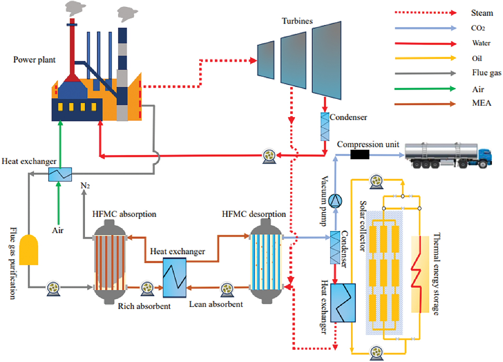
Figure 1: Process flow chart of proposed SOL-HFMC system
In this study, a 580 MWe supercritical coal-fired power plant is selected according to the performance parameters outlined in the NETL Fossil Energy Power Plant Baseline Study [21]. A 20 wt.% MEA solution is selected as the absorbent due to its high CO2 absorption capacity, low volatility, reduced regeneration energy requirements, widespread availability and cost-effectiveness [22]. Polypropylene (PP) hollow fiber membranes are chosen for their high porosity, established commercial use, cost-effectiveness, and superior chemical and thermal stability [23]. The flue gas from the power plant is cooled via an air-cooled heat exchanger and subjected to desulfurization and dust removal pretreatment before entering the hollow fiber membrane contactor. The treated flue gas primarily consists of N2 and CO2.
In the hydrophobic polypropylene hollow fiber membrane contactor, the flue gas and MEA solution countercurrently flow in the shell side and lumen side, respectively. The CO2 in the flue gas diffuses through the membrane’s micropores due to a concentration gradient, reaches the gas-liquid interface to be absorbed into the MEA solution. The hydrophobic nature of the polypropylene membrane prevents the MEA from entering the gas phase to avoid membrane wetting phenomenon. For membrane gas absorption system, the hydrophobic membrane does not provide the selectively and only serves as the gas-liquid interface. The CO2-rich absorbent is preheated in a heat exchanger and regenerated in another PP hollow fiber membrane contactor for desorption. In this unit, the CO2-rich absorbent flows through the lumen side, which contacts countercurrent sweep steam introduced from the bottom. The regenerated CO2-lean absorbent is collected from and reused in the absorption contactor for continuous CO2 removal.
As depicted in Fig. 1, solar energy primarily provides the thermal energy needed to regenerate the CO2-rich absorbent, supplemented by turbine-extracted steam during low solar availability. The desorption process operates at 80°C, with solar collectors operating within a 50°C–150°C temperature range. Evacuated tube collectors are chosen due to their cost efficiency and low maintenance requirements compared to other solar collector types [24]. These collectors use thermal oil as the heat transfer fluid, operating at low pressure to enhance system safety and performance. To address solar energy’s intermittent nature, a thermal energy storage (TES) system, designed based on Mokhtar et al. [25], is integrated to ensure consistent and efficient operation. Erythritol serves as the phase change material (PCM) in the TES system due to its excellent thermal properties.
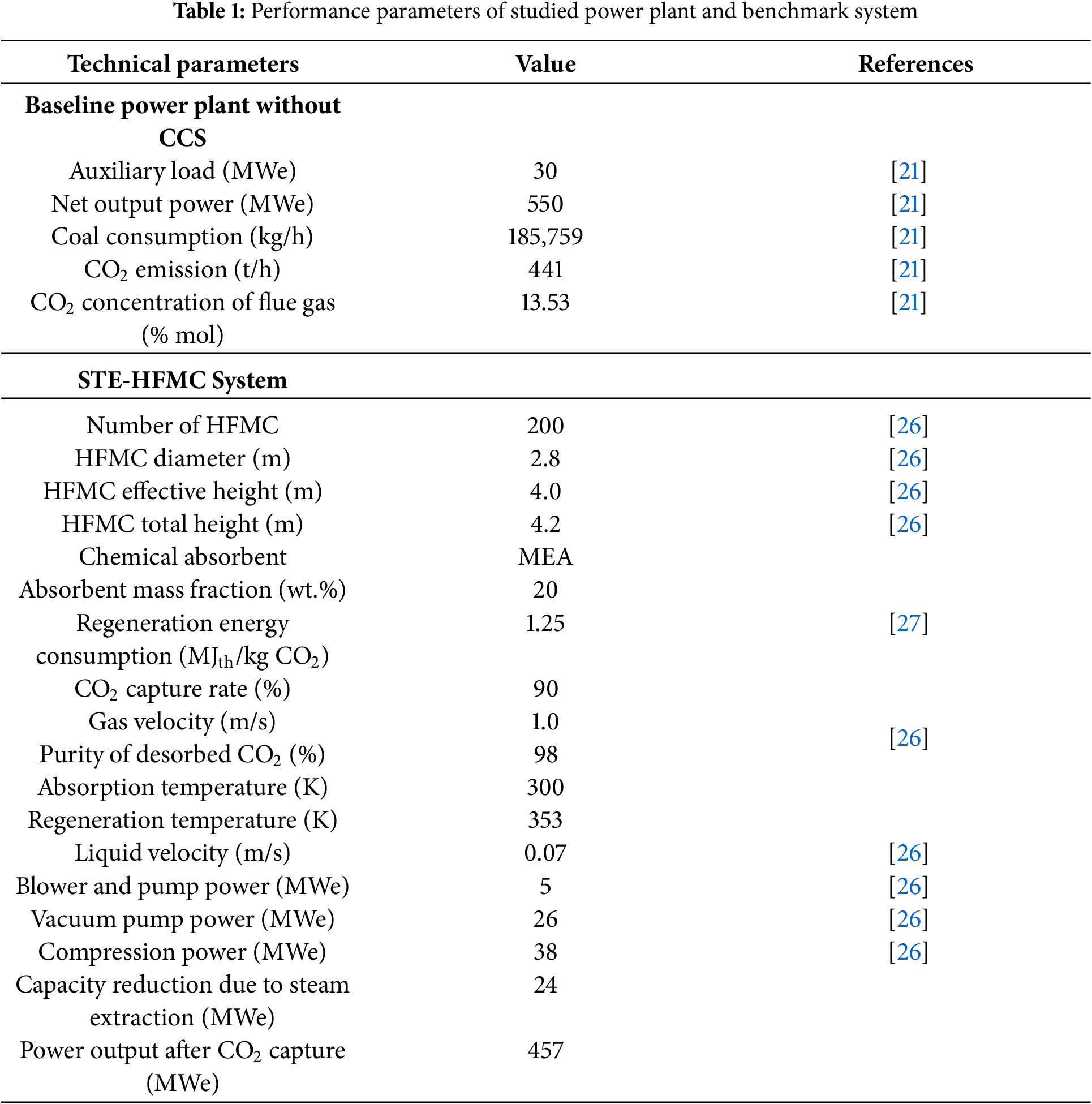
The analyzed power plant is presumed to operate continuously for 24 h daily, with a designated maintenance period in August. For comparison, a benchmark system which absorbs and desorbs CO2 in hollow fiber membrane contactors by 100% extracted steam is selected, namely STE-HFMC system. The specifications of the hollow fiber membrane contactor align with those detailed by Chen et al. [26]. The performance parameters of the studied power plant and benchmark system are given in Table 1.
3.1 Solar Collector Heat Collection and Solar Fraction
The thermal energy collected by the evacuated tube collector Q (kWh) can be calculated using the following formula:
where G is the total horizontal solar radiation, kWh/m2; S is the area of the evacuated tube collector, m2; and ηsolar is the thermal efficiency of the evacuated tube collector, calculated using Eq. (2):
where Tc is the temperature of the working fluid in the collector, K; Ta is the ambient temperature, K; and α0, α1, and α2 are the optical efficiency parameters of the evacuated tube collector, taking α0 = 0.71 m, α1 = 0.5 W/m2/K, α2 = 0.0035 W/m2/K2, respectively [28].
The SF is an indicator used to quantitatively assess the proportion of thermal energy provided by solar energy relative to the total energy required for the regeneration of the CO2-rich absorbent. SF effectively reflects the contribution of solar energy to the overall energy demand for regeneration. A higher solar fraction indicates greater reliance on renewable energy and reduced demand for steam extracted from the power plant’s turbine, which can be calculated using Eq. (3):
In this study, the area of the evacuated tube collector is designed based on the minimum heat collection per unit of sunshine duration per month. Under a given collector area, if the hourly heat collection by the solar collector exceeds the energy required for the regeneration of the CO2-rich absorbent, the excessive energy will be stored in the TES system for backup use. The thermal efficiency of a designated evacuated tube collector is significantly influenced by the solar irradiance striking its surface. Lhasa (29.6° N, 91.1° E), Xining (36.7° N, 101.7° E) and Jinan (36.5° N, 116.8° E) with different solar irradiation intensities are selected as the study case in the present study. The solar radiation, main meteorological parameters, collector area and SF of the three studied cities are detailed in our previous study [15]. Six scenarios with different system configurations have been considered in the present study as follows:
Scenario A: SOL-HFMC in Jinan without TES, with a SF of 28.19%, marked as Jinan-W/O;
Scenario B: SOL-HFMC in Xining without TES, with a SF of 30.26%, marked as Xining-W/O;
Scenario C: SOL-HFMC in Lhasa without TES, with a SF of 34.84%, marked as Lhasa-W/O;
Scenario D: SOL-HFMC in Jinan with TES, with a SF of 57%, marked as Jinan-W;
Scenario E: SOL-HFMC in Xining with TES, with a SF of 36.58%, marked as Xining-W;
Scenario F: SOL-HFMC in Lhasa with TES, with a SF of 42.22%, marked as Lhasa-W.
LCA is a widely recognized approach for assessing the environmental impacts of a product, process, or service across its entire life cycle, from raw material sourcing to final disposal or recycling. In the context of CO2 capture, LCA helps pinpoint significant environmental impacts throughout the capture process, enabling better decision-making for optimizing process design and enhancing sustainability. According to the ISO 14040:2006 and ISO 14044:2006 standards from the International Organization for Standardization [29,30], LCA consists of four main stages: defining the goal and scope, conducting life cycle inventory analysis, performing life cycle impact assessment, and interpreting the results.
3.2.1 Goal and Scope Definition
The goal and scope definition establishes the objectives, system boundaries, and functional unit of the LCA, forming the foundation for the analysis. This study aims to assess the environmental impacts of SOL-HFMC system, as well as the comparison with STE-HFMC system. A “gate-to-gate” rather than a “cradle-to-grave” approach is adopted in this study in order to focus on the CO2 capture and recovery processes within hollow fiber membrane contactors under the assistance of solar energy. It includes energy consumption and material flows involved in the CO2 capture process, solvent regeneration process, and solar energy supply process.
Fig. 2 illustrates the LCA boundaries of the SOL-HFMC system and STE-HFMC system. Due to data limitations, the current analysis excludes human labor consumption and the impact of human factors, consistent with the “1% rule” in life cycle assessment, which states that processes or factors contributing less than 1% to the overall assessment results can be neglected [31]. For the SOL-HFMC system, its primary function is to capture CO2 from flue gas. Therefore, this study defines the functional unit as “1 t of CO2 captured”.
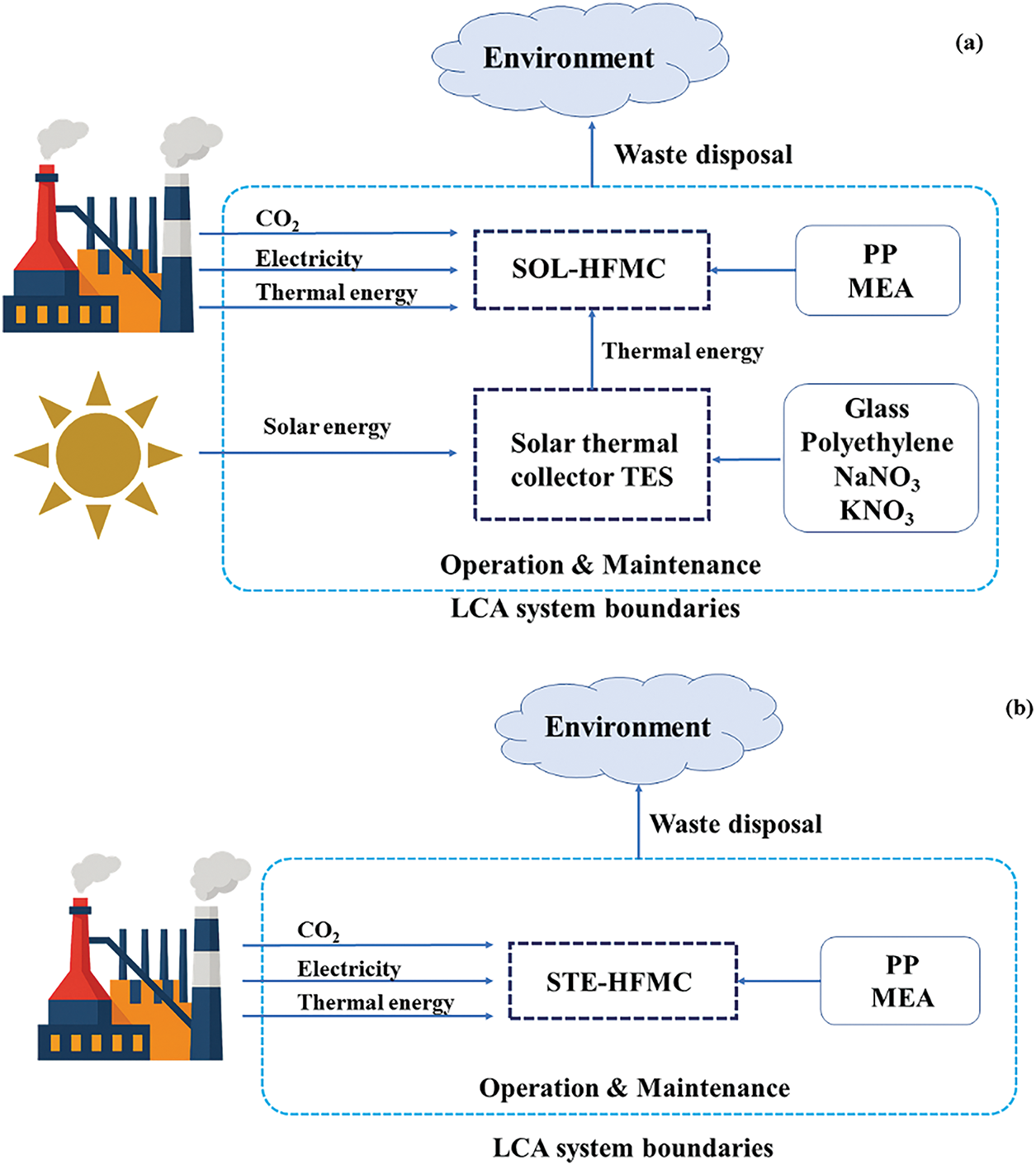
Figure 2: System boundaries for the (a) SOL-HFMC system and (b) STE-HFMC system
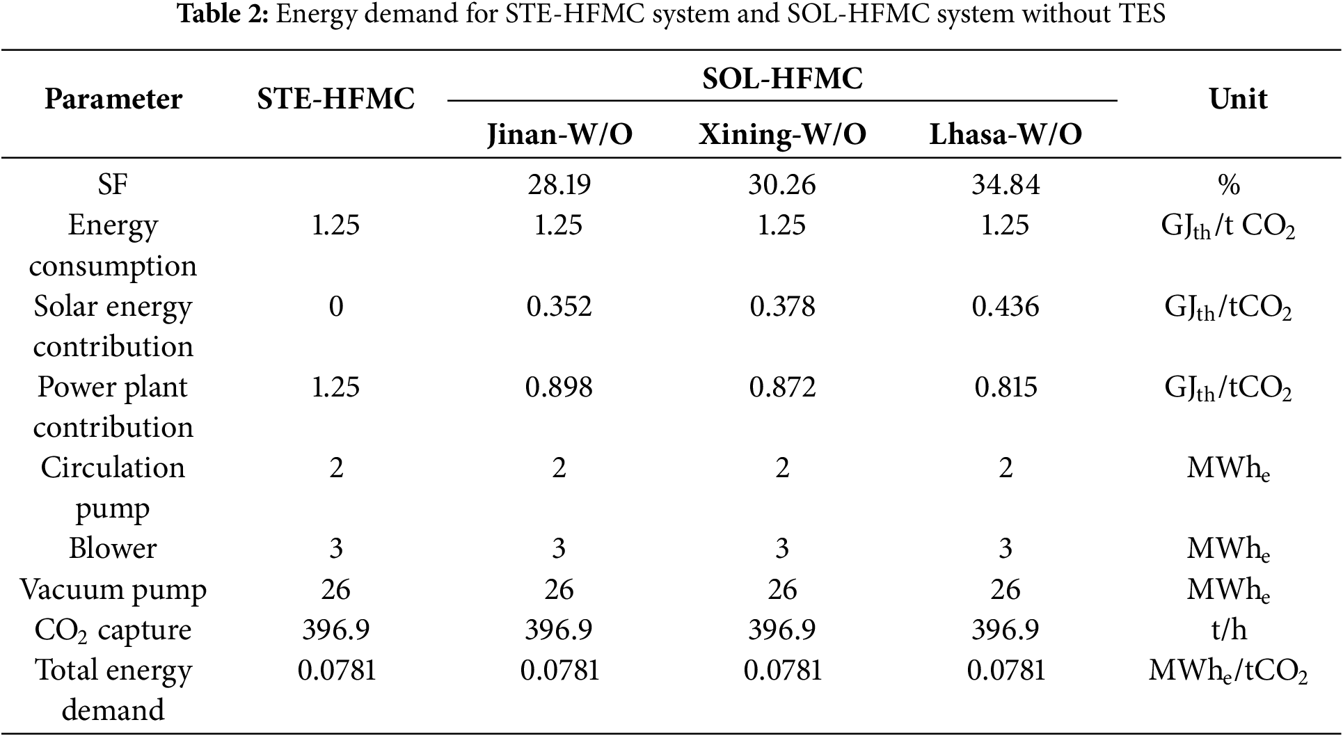
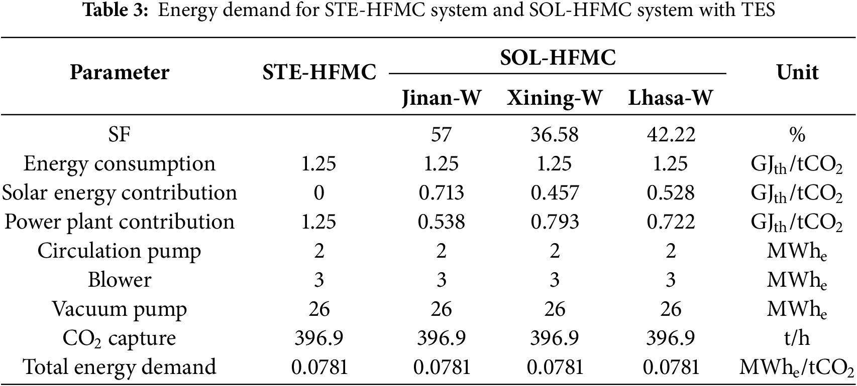
The life cycle assessment results depend on a comprehensive life cycle inventory which is defined by system boundaries, material flows, energy flows, and environmental relevance. In this study, the SOL-HFMC system is designed with an operational lifespan of 30 years and a capacity to process 441 t/h of CO2 emissions from a 580 MWe supercritical coal-fired power plant, achieving a 90% CO2 capture rate. System operation involves both thermal and electrical energy consumption. Thermal energy requirements include sensible heat for raising the absorbent temperature, reaction heat for CO2 desorption from the rich absorbent, and latent heat for water vaporization to facilitate CO2 stripping in the desorption membrane contactor. Electrical energy consumption is derived from the circulation pumps, blowers, and vacuum pumps. For both the STE-HFMC and SOL-HFMC systems, the energy demand for solvent regeneration remains constant. However, variations in the solar fraction across the SOL-HFMC systems in Jinan, Xining, and Lhasa result in different reliance on steam extraction from the power plant. Detailed energy inventory data for these scenarios are presented in Tables 2 and 3.
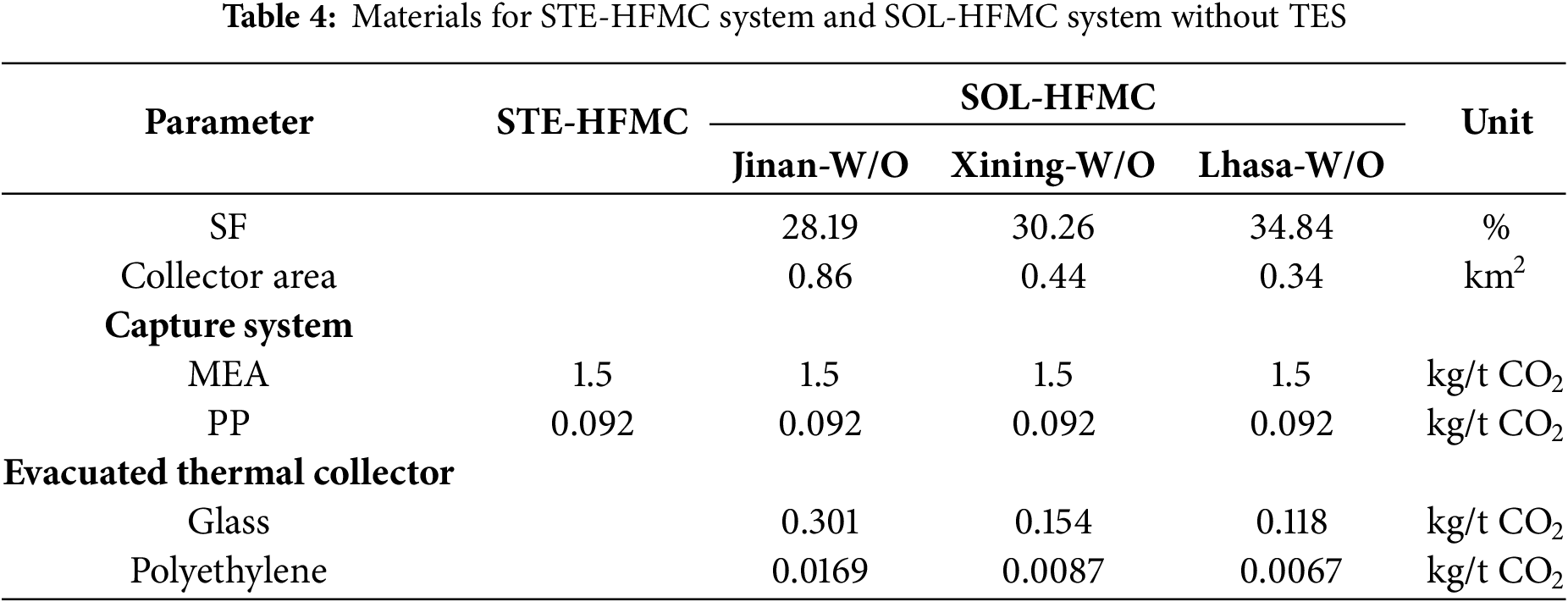
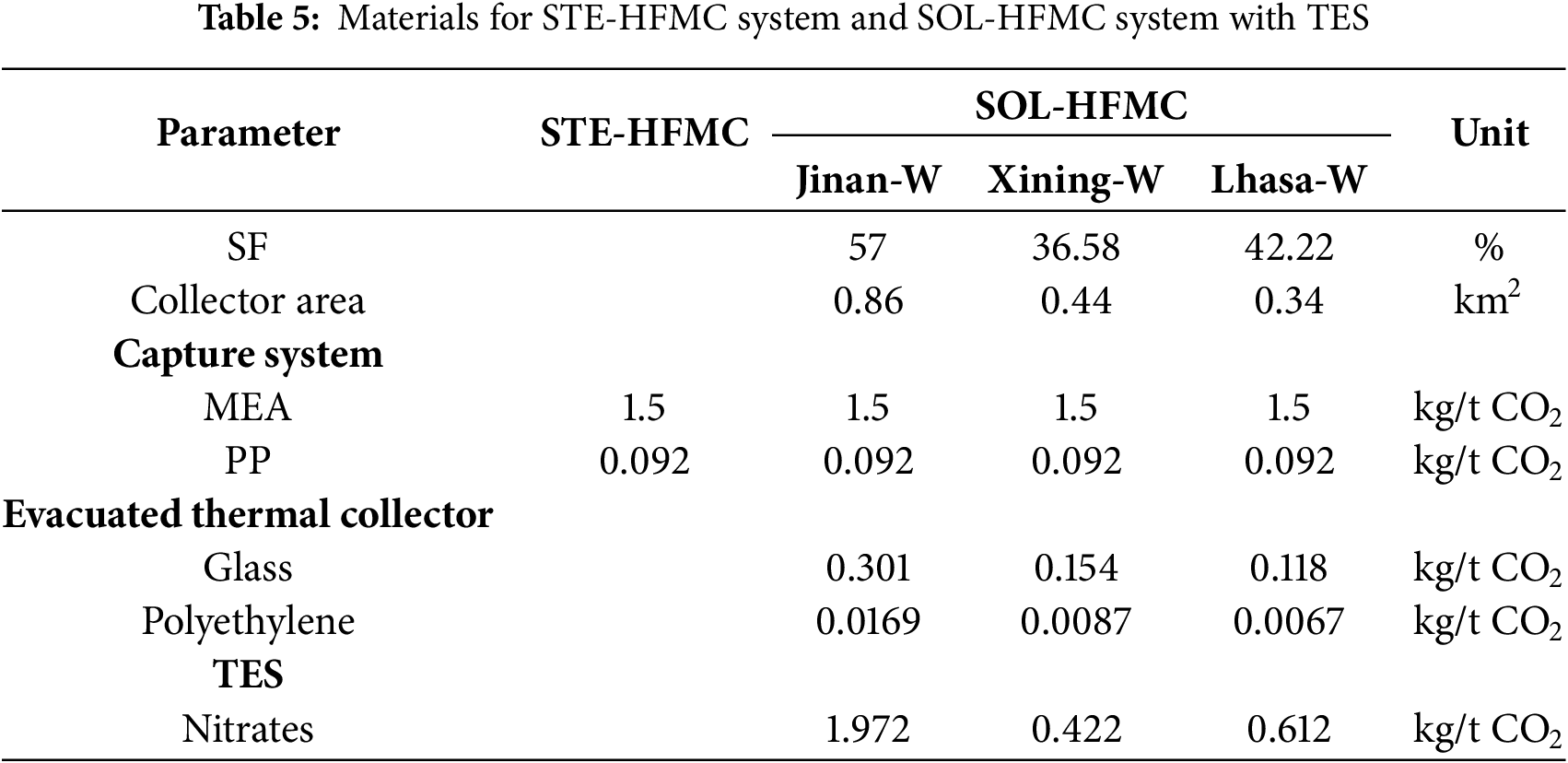
During the operation of the membrane contactor capture unit, material consumption primarily arises from membrane materials and absorbents, with antioxidants and corrosion inhibitors excluded from this analysis due to their minimal contributions. The material of the hollow fiber membrane contactors is made of polypropylene, with raw material consumption data for its production sourced from the Eco-invent database. The membrane has a lifespan of 15 years, requiring one replacement over the system’s 30-year operational lifespan. The absorbent is consumed at a rate of 1.5 kg per ton of CO2 captured. In the evacuated tube collector, getter materials are used to absorb gases and maintain the vacuum integrity within the vacuum layer. These materials have an estimated lifespan of 15 years, after which the thermal efficiency of the vacuum tubes declines due to diminished vacuum levels [32]. Consequently, the lifespan of the evacuated tube collector is set at 10 years, requiring two replacements over the system’s 30-year operational lifespan [33]. Similarly, the PCM, composed of 54% KNO3 and 46% NaNO3, requires two replacements within the same operation period [34]. Detailed material data for the studied systems are presented in Tables 4 and 5, respectively. Inputs and outputs for producing 1000 m2 of hollow fiber membrane and 1 kg of MEA are given in our previous study [35].
3.2.3 Life Cycle Impact Assessment
This study utilizes a set of 11 environmental impact indicators derived from the ReCiPe 2016 methodology to comprehensively evaluate environmental impacts across diverse ecological and human health domains. These indicators include Global Warming (GW), Stratospheric Ozone Depletion (SOD), Terrestrial Acidification (TA), Freshwater Eutrophication (FEU), Marine Eutrophication (MEU), Terrestrial Ecotoxicity (TE), Freshwater Ecotoxicity (FEC), Marine Ecotoxicity (MEC), Human Carcinogenic Toxicity (HCT), Human Non-Carcinogenic Toxicity (HNCT), and Fossil Resource Scarcity (FRS).
The interpretation stage is the final phase where the results of the LCA are analyzed, evaluated and synthesized to draw conclusions and provide recommendations for CO2 capture decision-making. Interpretation ensures that the findings from the inventory analysis and impact assessment phases are meaningful, reliable, and actionable.
4.1 Environmental Impact under Different Scenarios
Table 6 shows the environmental impact assessment scores for SOL-HFMC system without TES, with STE-HFMC system as the benchmark. In comparison with the STE-HFMC system, the SOL-HFMC system demonstrates reduced contributions to environmental impact indicators. GW, predominantly driven by CO2 and CH4 emissions, is significantly influenced by the high energy demands of the solvent regeneration process, which accelerates indirect emissions during fuel and electricity consumption. In scenarios lacking TES, the global warming indicator values for capturing 1 t of CO2 are 2.55 × 10² kg CO2 eq in Jinan, 2.53 × 10² kg CO2 eq in Xining, and 2.49 × 10² kg CO2 eq in Lhasa. It represents a reduction of 7.61%, 8.33%, and 9.78% compared to the STE-HFMC system, respectively. This enhanced performance is attributed to the utilization of solar energy of SOL-HFMC system, which substitutes steam extraction and thereby diminishes the thermal energy demand from power plants during solvent regeneration.
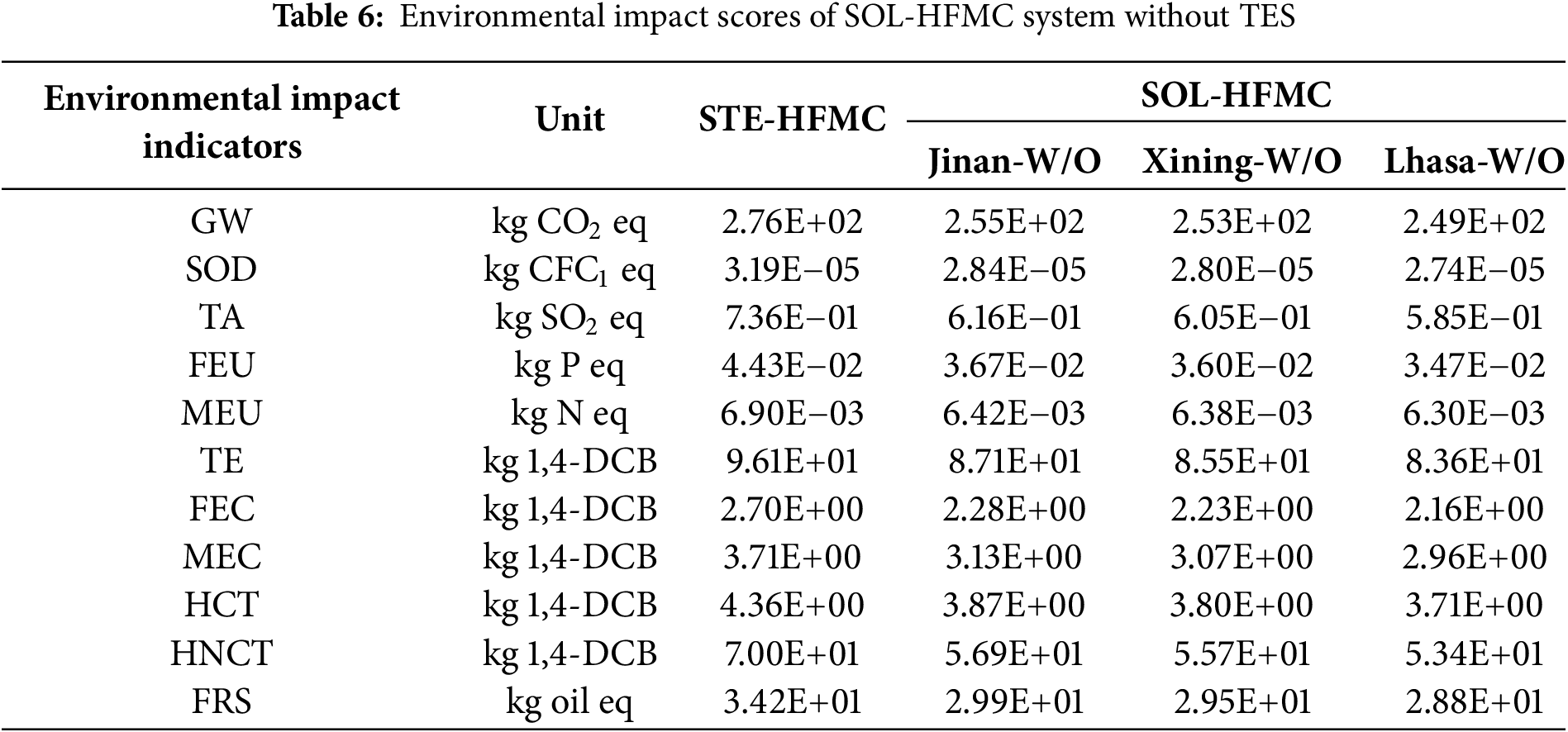
The contribution percent of the environmental impact assessment for studied CO2 capture systems is shown in Fig. 3. The highest value in each impact category is taken as the 100% reference value, while other categories with lower values are expressed as ratios relative to the reference value. As shown in Table 6 and Fig. 3, across all assessed categories, the environmental impact follows the order of Jinan > Xining > Lhasa. It indicates that the proposed SOL-HFMC system has a lower environmental impact in regions with more abundant solar resources, so the system has potential for greater ecological benefits in such regions.
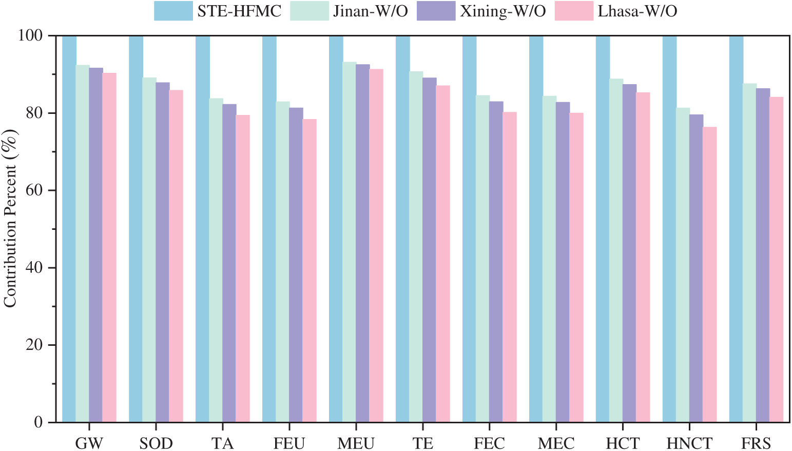
Figure 3: Contribution of STE-HFMC system and SOL-HFMC system without TES
Table 7 and Fig. 4 present the environmental impact assessment scores and contribution percent for STE-HFMC system and SOL-HFMC system with TES, respectively. Across all environmental indicators, GW exhibits the highest impact across all indicators, while SOD shows the lowest. Compared to scenarios without TES, most environmental impact scores in three studied cities are reduced. It can be attributed to the TES integration which lowers the scores related to power plant steam consumption. However, for environmental indicators significantly influenced by the TES system itself, such as SOD and MEU, the scores exhibit an increase. In comparison with STE-HFMC system, most environmental indicators of SOL-HFMC system have lower scores, but indicators heavily influenced by the TES system records higher values, such as SOD and MEU. Specifically, in scenarios of SOL-HFMC with TES, the stratospheric ozone depletion values for capturing 1 t of CO2 are 1.53 × 10⁻⁴ kg CFC-11 eq in Jinan, 5.47 × 10⁻⁵ kg CFC-11 eq in Xining, and 6.64 × 10⁻⁵ kg CFC-11 eq in Lhasa, reflecting an increase of 379.94%, 71.47%, and 108.15%, respectively, relative to the STE-HFMC system.
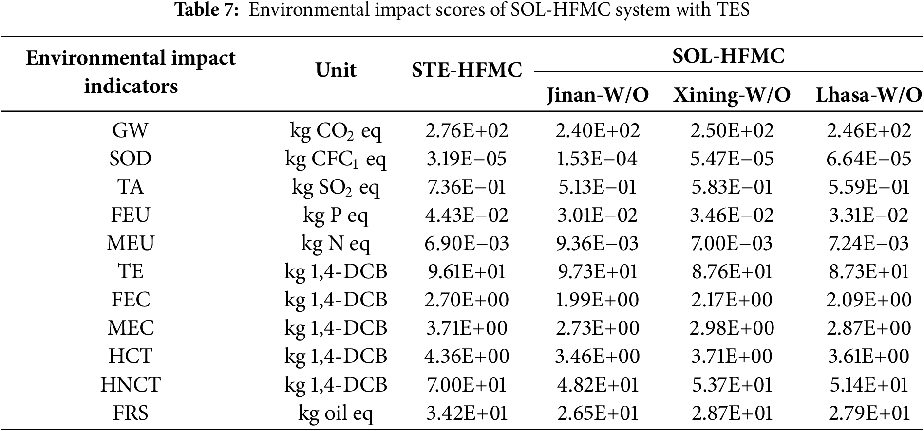
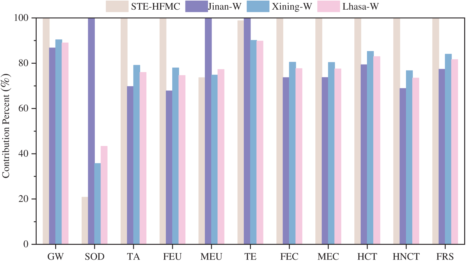
Figure 4: Contribution of STE-HFMC system and SOL-HFMC system with TES
4.2 Environmental Impact under Different Scenarios
Fig. 5 presents a detailed analysis of the relative contributions of various factors involved in SOL-HFMC system to environmental impacts across Scenarios A, B and C. It can be observed that, electricity consumption and power plant steam consumption are the dominant contributors during the operational phase, with their impacts varying by region and environmental indicator. Electricity consumption accounts for 15% to 64% of environmental impacts across most indicators, surpassing 32% for all except MEU. Its most pronounced effect is observed in SOD, with contributions of 62%, 63%, and 64% for Scenarios A, B, and C, respectively. This is primarily due to chlorofluorocarbon decomposition under ultraviolet radiation, which releases chlorine atoms that catalyze ozone depletion. Conversely, power plant steam consumption contributes 18% to 61% across environmental indicators, with its most substantial impact on HNCT, with contribution rates of 61%, 60%, and 59% for Scenarios A, B, and C, respectively. The result indicates a progressive increase in the environmental impact of electricity consumption from Scenario A to Scenario C, coupled with a corresponding decrease in the impact of power plant steam consumption. The reason is that, the higher solar fraction in Lhasa under Scenario C reduces reliance on power plant steam, thereby diminishing its environmental footprint while amplifying the relative impact of electricity consumption.
Figure 5: Contribution of SOL-HFMC system without TES: (a) Jinan-W/O; (b) Xining-W/O; (c) Lhasa-W/O
Eutrophication refers to the excessive growth of aquatic organisms caused by an overabundance of nutrients in ecosystems, particularly nitrogen and phosphorus, with FEU primarily linked to phosphates and MEU associated with nitrogen compounds. The MEA absorbent used in the membrane contactor contributes 65%, 66%, and 67% to ME impacts in Scenarios A, B, and C, respectively, due to ammonia release during its use. The membrane material and evacuated tube collector contribute less than 2% to all environmental indicators throughout the system’s operational phase. Additionally, uncaptured CO2 contributes 44%, 44%, and 45% to GW in Scenarios A, B, and C, respectively, indicating that reducing fugitive emissions is a critical measure for lowering the system’s environmental impact.
Fig. 6 present the contributions of various factors to environmental impacts in scenarios incorporating TES. Consistent with non-TES scenarios, power plant steam consumption and electricity consumption dominate most environmental impact indicators during the operational phase of TES scenarios. However, for most indicators, excluding SOD, MEU, and TE, electricity consumption in TES scenarios exerts a greater environmental impact than in non-TES scenarios. For instance, in Jinan, electricity consumption contributes 32% to GW in Scenario A, compared to 34% in Scenario D. The environmental impact of power plant steam consumption is diminished in TES scenarios due to the integration of TES, which enables solar energy to supplant a larger fraction of steam extraction from power plants. The significant contributions of electricity and steam consumption reveal the system’s heavy reliance on fossil fuels, which poses risks to environmental resource sustainability. For example, in Lhasa, power plant steam consumption’s contribution to FRS in Scenario F is reduced by 3% compared to Scenario C, showing TES’s potential to mitigate fossil resource depletion.
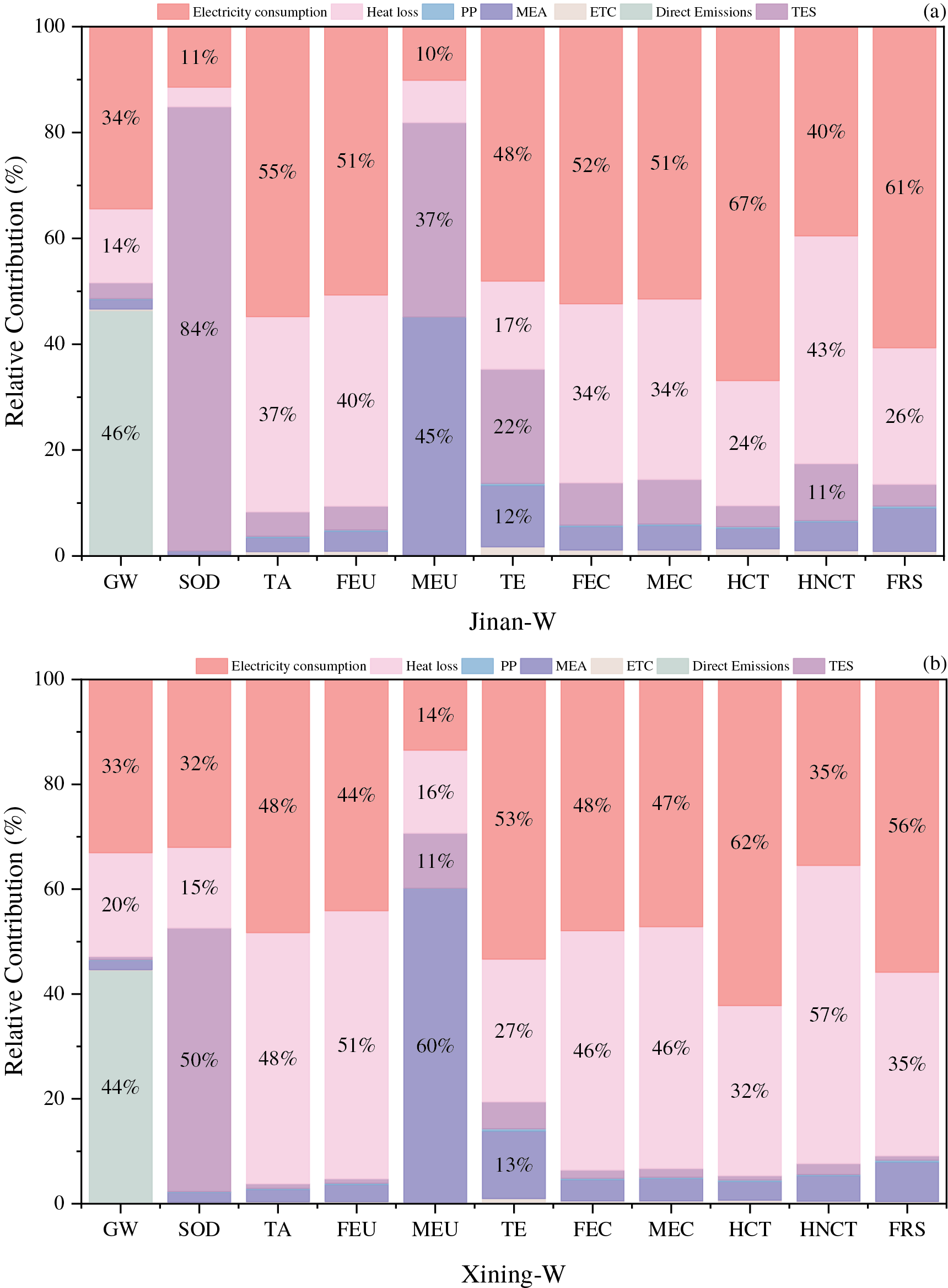
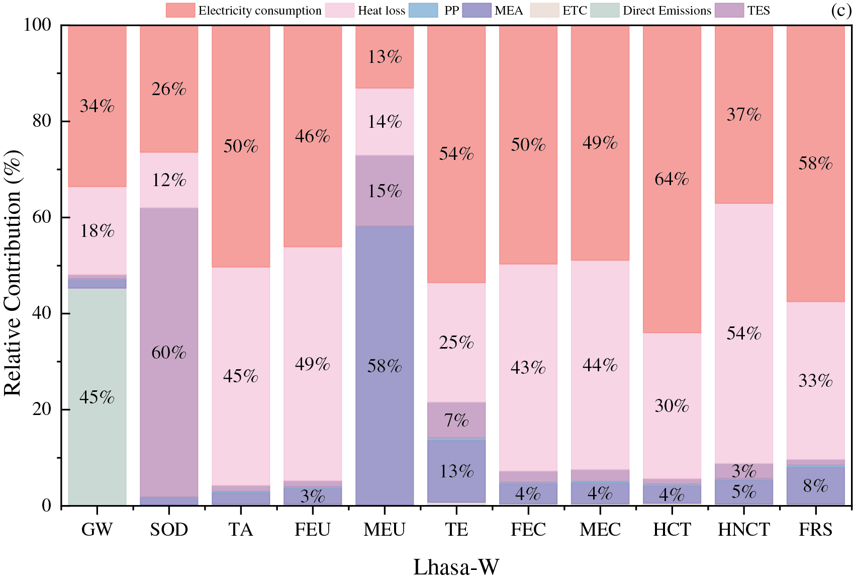
Figure 6: Contribution of SOL-HFMC system with TES: (a) Jinan-W; (b) Xining-W; (c) Lhasa-W
Nevertheless, TES introduce additional environmental impacts, particularly in SOD, MEU, and TE. In Scenarios D, E, and F, TES systems contribute 84%, 50%, and 60% to SOD, respectively, driven by the use of nitrate-based phase change materials. Among TES scenarios, Scenario E exhibits the lowest contribution to MEU, attributable to its smaller TES system scale, which results in reduced nitrogen oxide emissions. This suggests that smaller TES systems correlate with lower contributions to MEU due to decreased nitrogen oxide emissions. TE, primarily driven by pollutants such as mercury, acrolein, beryllium, and barium, adversely affects soil biodiversity and ecological balance. Contribution rates to TE in Scenarios D, E, and F are 22%, 5%, and 7%, respectively, indicating the dependence of environmental impacts of TES system scales.
4.3.1 Influence of Solar Fraction on SOL-HFMC System without TES
The power plant steam consumption required by the SOL-HFMC system is influenced by the SF, which directly affects the system’s environmental impact scores. Figs. 7 and 8 illustrate the contribution rates of operating parameters to environmental impact indicators for the SOL-HFMC system at solar fraction values of 28.24% and 33.11%, respectively. The analysis of Figs. 7 and 8 reveals that as SF increases, the contribution of power plant steam consumption to environmental impact indicators decreases. This reduction is less pronounced for indicators such as MEU, TE, and FRS, primarily due to the dominant influence of MEA usage, which maintains a high contribution rate. It indicates that while higher SF reduces reliance on steam, the environmental burden of MEA limits the overall improvement for these indicators.

Figure 7: Sensitivity analysis for SOL-HFMC system without TES at SF = 28.24
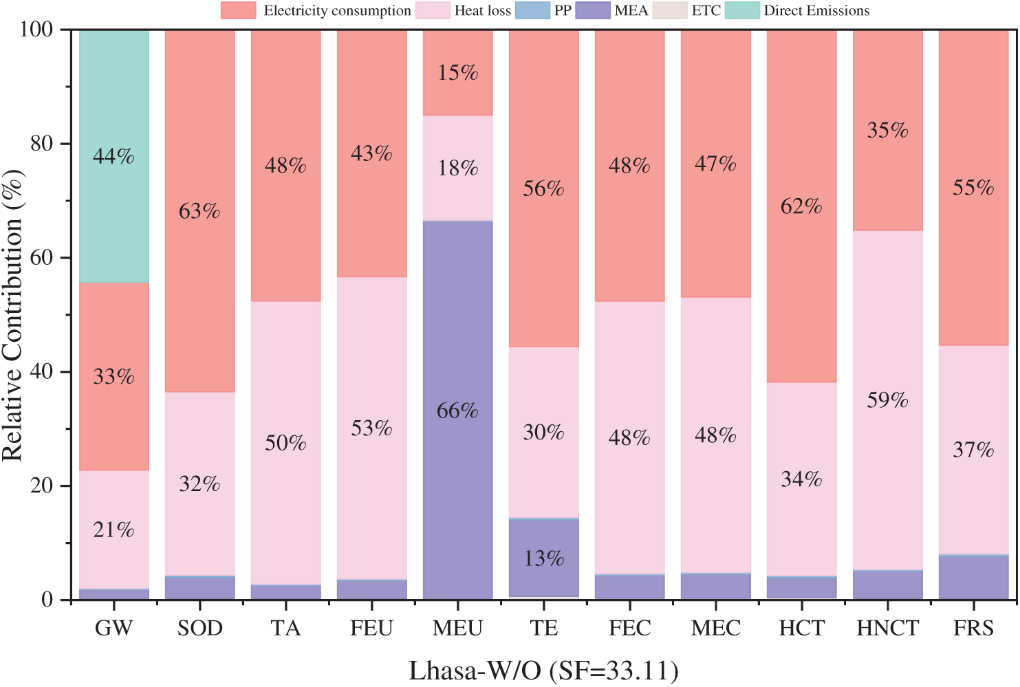
Figure 8: Sensitivity analysis for SOL-HFMC system without TES at SF = 33.11
Fig. 9 compares the SOL-HFMC system without thermal energy storage to the STE-HFMC system at SF values of 28.24%, 33.11%, and 34.84%. Fig. 9 highlights that the SOL-HFMC system in Lhasa, without TES, achieves significantly lower environmental impact scores compared to the STE-HFMC system. This reduction is directly tied to increasing SF values, indicating that greater solar energy utilization substantially enhances the sustainability of the carbon capture system. Specifically, as SF rises, the environmental impact scores of the SOL-HFMC system decrease further, revealing the effectiveness of solar energy in reducing the system’s environmental footprint. Among the indicators, HNCT shows the most significant improvement, with contribution rates reduced by 19.27% at SF = 28.24% and 22.59% at SF = 33.11% compared to the STE-HFMC system. The obvious decrease in HNCT reflects the system’s improved performance in mitigating toxic impacts through solar energy integration.
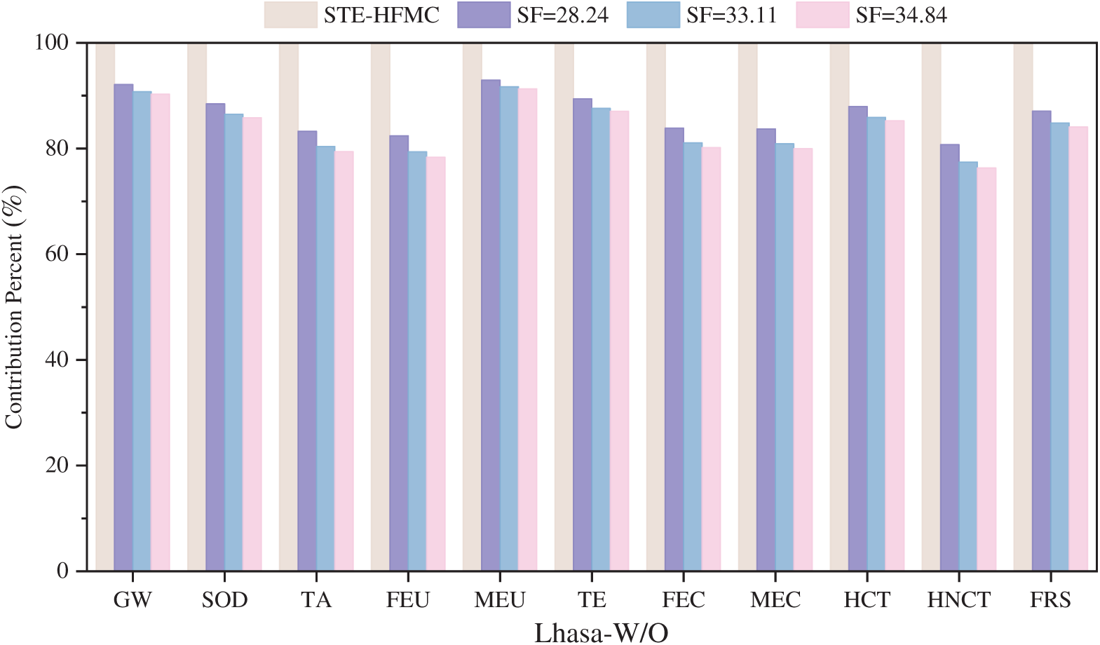
Figure 9: Environmental impacts for SOL-HFMC system without TES at varying SFs
4.3.2 Influence of Solar Fraction on SOL-HFMC System with TES
Figs. 10 and 11 depict the relative contribution rates of various factors to environmental impact indicators for the SOL-HFMC system with thermal energy storage at solar fraction values of 28.24% and 35.07%, respectively. The analysis reveals that electricity consumption and power plant steam consumption remain the primary drivers of environmental impacts, with TES also exerting a notable influence. As the SF increases in the SOL-HFMC system equipped with TES, the contribution of power plant steam heat consumption to environmental impacts diminishes. This trend indicates that higher solar fractions reduce the reliance on steam-based energy, thereby lowering its environmental footprint. Conversely, an increase in SF leads to greater thermal energy storage requirements, which amplifies the environmental impact of the TES system. While higher SF values enhance the system’s sustainability by reducing steam consumption, they simultaneously increase the environmental burden of TES.
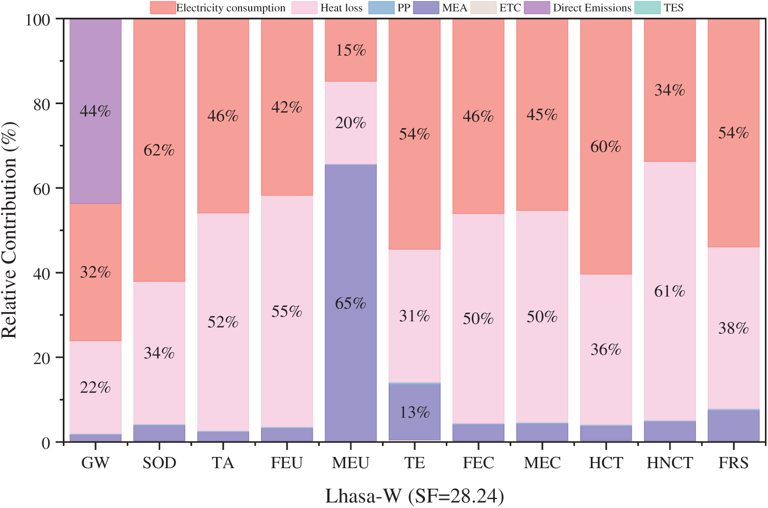
Figure 10: Sensitivity analysis for SOL-HFMC system with TES at SF = 28.24
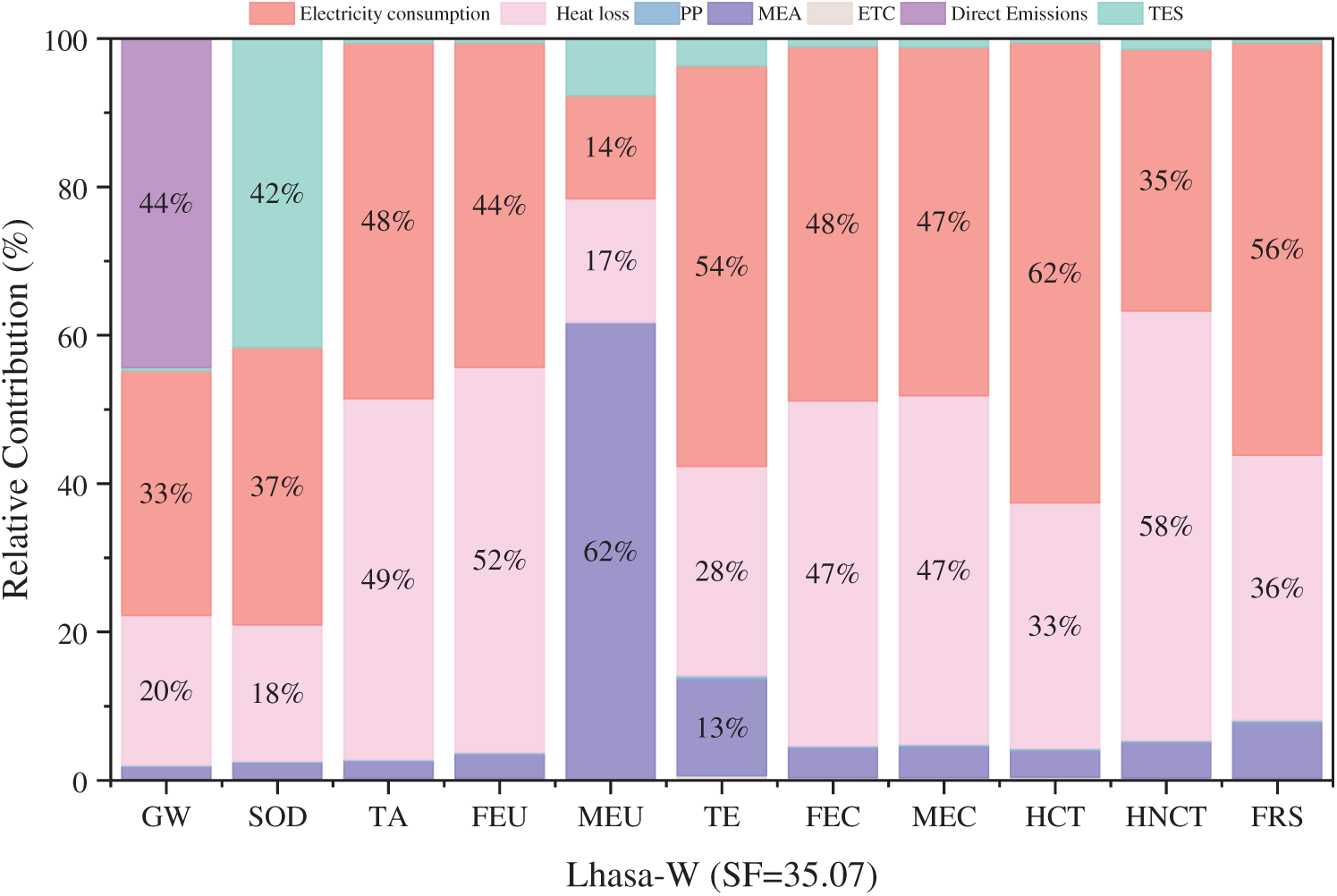
Figure 11: Sensitivity analysis for SOL-HFMC system with TES at SF = 35.07
Fig. 12 presents a comparative analysis of environmental impact assessment scores for the SOL-HFMC system across three SF scenarios: 28.24%, 35.07%, and 42.22%. As SF increases, the reliance on power plant steam consumption decreases, as evidenced by the declining contributions to environmental indicators shown in Figs. 10 and 11, reflecting a reduced dependency on fossil fuel-based energy inputs. However, this shift elevates thermal energy storage demands, significantly increasing the TES system’s environmental footprint, with its contribution to certain indicators rising from 20% to 44%. Specifically, higher SF levels correlate with increased scores for SOD, MEU, and TE, surpassing the STE-HFMC system’s performance at an SF of 35.07% for SOD and at 42.22% for both SOD and MEU. This suggests that while higher SF enhances solar energy utilization, it amplifies specific environmental burdens due to intensified TES requirements. Conversely, indicators like human toxicity show improvement with higher SF, indicating a trade-off in environmental impacts. Therefore, it can be concluded that, there is a need for a balanced SF optimization strategy, carefully weighing the benefits of reduced steam consumption against the increased ecological costs of TES expansion, to minimize the SOL-HFMC system’s overall environmental footprint while maximizing its sustainability benefits.
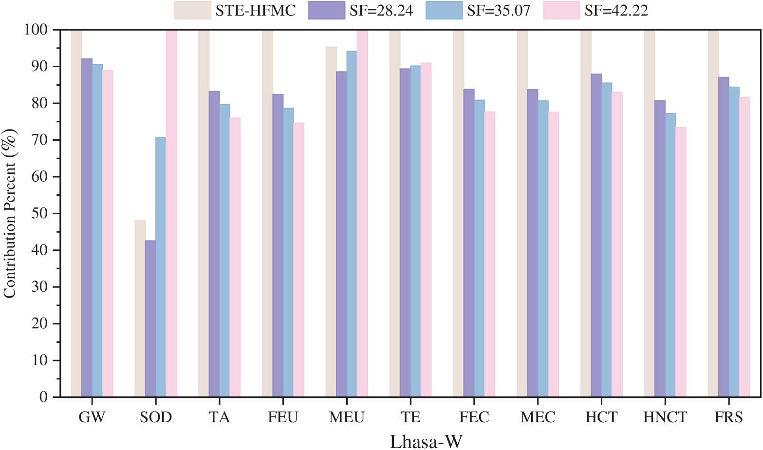
Figure 12: Environmental impacts for SOL-HFMC system with TES at varying SFs
In the present study, SimaPro 9 software is utilized to evaluate the environmental impact of the proposed SOL-HFMC system with or without TES during the operational phase of a 580 MWe supercritical coal-fired power plant. Additionally, a sensitivity analysis of the solar fraction is performed on the SOL-HFMC system in Lhasa to investigate its influence on the system’s environmental footprint. The following conclusion can be drawn:
(1) Within the SOL-HFMC system, steam heat consumption and electricity usage in the power plant is the predominant contributors to environmental impacts throughout the life cycle. The TES system owing to its phase-change materials also has a significant influence on environmental indicators, with a particularly significant effect on SOD.
(2) Among the six studied scenarios, GW shows the highest environmental impact, whereas SOD records the lowest. In comparison with the STE-HFMC system, all six scenarios exhibit a substantial reduction in GW potential, which indicates the effectiveness of integrating solar collectors in mitigating the system’s contribution to GW.
(3) The environmental impact attributable to steam heat consumption diminishes with increasing SF. Compared to the STE-HFMC system, the SOL-HFMC system without TES demonstrates lower impact scores across all environmental indicators, with this reduction becoming more significant as SF increases. In the SOL-HFMC system equipped with TES, most environmental impacts exhibit a declining trend as SF rises. However, SOD, MEU, and TE are strongly influenced by TES, which display an upward trend in impact scores with increasing SF.
Certain limitations must be acknowledged to contextualize the findings and guide future research. First, the gate-to-gate LCA boundary, while suitable for isolating operational impacts, excludes environmental contributions from equipment manufacturing, maintenance, and end-of-life disposal of key components, such as polypropylene membranes and nitrate-based phase change materials in the thermal energy storage system. Conducting a cradle-to-grave LCA, including alternative materials like organic or nano-composite PCMs, was constrained by data availability and resource limitations in this study. Future work will prioritize a comprehensive cradle-to-grave approach to capture these impacts fully. Second, the analysis assumes a fixed CO2 capture efficiency derived from experimental data, limiting insights into the sensitivity of LCA outcomes to operational variations. Evaluating strategies to enhance capture efficiency and their environmental implications was beyond the scope of this study’s baseline comparison. Subsequent research will incorporate sensitivity analyses to assess how operational parameters affect global warming potential and other impact categories, enabling a more robust evaluation of technological improvements. Third, the study’s geographical scope, limited to Jinan, Xining, and Lhasa in China, restricts the generalizability of findings to high-solar-radiation regions like the Middle East, Australia, or Spain. Future studies will develop region-specific sensitivity models and include case studies from diverse global contexts to enhance the applicability of the SOL-HFMC and STE-HFMC frameworks.
Acknowledgement: Not applicable.
Funding Statement: This research was funded by State Key Laboratory of Intelligent Construction and Healthy Operation and Maintenance of Deep Underground Engineering, grant number SDGZ2524; Shandong Province Science and Technology Smes Ability Improvement Project, grant number 2025TSGCCZZB0258; Major Innovation Project of Qilu University of Technology (Shandong Academy of Sciences), grant number 2025ZDZX03.
Author Contributions: The authors confirm contribution to the paper as follows: Conceptualization, Lei Wang, Hongyang Zhou and Junkun Mu; methodology, Lei Wang, Hongyang Zhou and Junkun Mu; software, Hongyang Zhou and Junkun Mu; validation, Xiaofan Liu and Jinpeng Bi; formal analysis, Lei Wang, Hongyang Zhou, Junkun Mu and Youkang Jin; resources, Lei Wang; data curation, Hongyang Zhou and Junkun Mu; writing—original draft preparation, Lei Wang, Hongyang Zhou and Junkun Mu; writing—review and editing, Yuexia Lv, Youkang Jin and Juan Ge; visualization, Hongyang Zhou and Jinpeng Bi; supervision, Xiaofan Liu and Yuexia Lv; project administration, Yuexia Lv and Juan Ge; funding acquisition, Yuexia Lv and Juan Ge. All authors reviewed the results and approved the final version of the manuscript.
Availability of Data and Materials: Data available on request from the authors.
Ethics Approval: Not applicable.
Conflicts of Interest: The authors declare no conflicts of interest to report regarding the present study.
References
1. IEA (International Energy Agency). Global energy review 2025. Paris, France: International Energy Agency (IEA). 2025 Mar [cited 2025 Apr 5]. Available from: https://www.iea.org/reports/global-energy-review-2025. [Google Scholar]
2. IPCC (Intergovernmental Panel on Climate Change). Special Report on Global Warming of 1.5°C: An IPCC special report on the impacts of global warming of 1.5°C above pre-industrial levels and related global greenhouse gas emission pathways, in the context of strengthening the global response to the threat of climate change, sustainable development, and efforts to eradicate poverty. Geneva, Switzerland: Intergovernmental Panel on Climate Change (IPCC). 2018 Oct 8 [cited 2024 Oct 7]. Available from: https://www.ipcc.ch/sr15/. [Google Scholar]
3. International Energy Agency (IEA). Energy technology perspectives 2020: special report on carbon capture utilisation and storage. Paris, France: International Energy Agency (IEA). 2020 Oct 19 [cited 2025 May 1]. Available from: https://iea.blob.core.windows.net/assets/. [Google Scholar]
4. Cheng Z, Li Z, Liu P. Amine-based CO2 capture using hollow fiber membrane contactors in a coal-fired power plant: an absorption-desorption-combined plant-scale techno-economic analysis. Energy. 2025;320:135415. doi:10.1016/j.energy.2025.135415. [Google Scholar] [CrossRef]
5. Eskandari M, Khaksar SAN, Keshavarz P. CO2 absorption using benzylamine as absorbent and promoter in a hollow fiber membrane contactor: a numerical study. J CO2 Util. 2022;66:102287. doi:10.1016/j.jcou.2022.102287. [Google Scholar] [CrossRef]
6. Bozonc AC, Gómez-Coma L, Díaz-Sainz G, Irabien A, Cormos AM. Computational fluid dynamics investigation of CO2 absorption using ionic liquids in hollow-fiber membrane contactors. Chem Eng J. 2025;519:165308. doi:10.1016/j.cej.2025.165308. [Google Scholar] [CrossRef]
7. Jiang Y, Zhang Z, Fan J, Yang L, Liu J. Experimental study on post combustion systems including a hollow fiber membrane and a packed column. ACS Omega. 2020;5(28):17692–702. doi:10.1021/acsomega.0c02251. [Google Scholar] [PubMed] [CrossRef]
8. Xue K, Zhan G, Wu X, Zhang H, Chen Z, Chen H, et al. Integration of membrane contactors and catalytic solvent regeneration for efficient carbon dioxide capture. J Membr Sci. 2023;684:121870. doi:10.1016/j.memsci.2023.121870. [Google Scholar] [CrossRef]
9. Nguyen K, Iliuta I, Bougie F, Pasquier LC, Iliuta MC. Techno-economic assessment of enzymatic CO2 capture in hollow fiber membrane contactors with immobilized carbonic anhydrase. Sep Purif Technol. 2023;307:122702. doi:10.1016/j.seppur.2022.122702. [Google Scholar] [CrossRef]
10. Dong Z, Ye X, Jiang J, Li C. Life cycle assessment of coal-fired solar-assisted carbon capture power generation system integrated with organic Rankine cycle. J Clean Prod. 2022;356:131888. doi:10.1016/j.jclepro.2022.131888. [Google Scholar] [CrossRef]
11. Chen B, Deng S, Zhao L, Li S, Wu K, Chen L, et al. Performance analysis of solar-assisted CO2 adsorption capture system based on dynamic simulation. Sol Energy. 2020;209:628–45. doi:10.1016/j.solener.2020.09.017. [Google Scholar] [CrossRef]
12. Bravo J, Charles J, Neti S, Caram H, Oztekin A, Romero C. Integration of solar thermal energy to improve NGCC with CO2 capture plant performance. Int J Greenh Gas Control. 2020;100:103111. doi:10.1016/j.ijggc.2020.103111. [Google Scholar] [CrossRef]
13. Farzin H, Hosseinpour M, Salimi M, Amidpour M. Toward a greener future: solar solutions for industrial carbon capture. Sol Energy. 2024;271:112436. doi:10.1016/j.solener.2024.112436. [Google Scholar] [CrossRef]
14. Javad A, Kazempoor P. Advancing power plant decarbonization with a flexible hybrid carbon capture system. Energy Convers Manage. 2024;299:117821. doi:10.1016/j.enconman.2023.117821. [Google Scholar] [CrossRef]
15. Mu J, Bi J, Lv Y, Su Y, Zhao W, Zhang H, et al. Techno-economic evaluation on solar-assisted post-combustion CO2 capture in hollow fiber membrane contactors. Energies. 2024;17(9):2139. doi:10.3390/en17092139. [Google Scholar] [CrossRef]
16. Jung HS, Ryoo SG, Kang YT. Life cycle environmental impact assessment of Taean coal power plant with CO2 capture module. J Clean Prod. 2022;357:131663. doi:10.1016/j.jclepro.2022.131663. [Google Scholar] [CrossRef]
17. Volkart K, Bauer C, Boulet C. Life cycle assessment of carbon capture and storage in power generation and industry in Europe. Int J Greenh Gas Control. 2013;16:91–106. doi:10.1016/j.ijggc.2013.03.003. [Google Scholar] [CrossRef]
18. Wang P, Liu Z, Pan Z, González-Arias J, Shang L, Wang Y, et al. Advances in life cycle assessment of chemical absorption-based carbon capture technologies. Sep Purif Technol. 2024;346:127252. doi:10.1016/j.seppur.2024.127252. [Google Scholar] [CrossRef]
19. Kev K, Modi N, Milani D, Luu MT, Nelson S, Manaf NA, et al. A comparative life cycle impact assessment for solar heat integration in post-combustion carbon capture. Energy Convers Manage. 2023;297:117745. doi:10.1016/j.enconman.2023.117745. [Google Scholar] [CrossRef]
20. Rizwan R, Javed H, Rizwan A, Sharif F, Yasar A, Tabinda AB, et al. Life cycle assessment of a cleaner supercritical coal-fired power plant. J Clean Prod. 2021;279:123869. doi:10.1016/j.jclepro.2020.123869. [Google Scholar] [CrossRef]
21. Cost NETL. Performance baseline for fossil energy plants, volume 1: bituminous coal and natural gas to electricity, revision 2. Albany, OR, USA: National Energy Technology Laboratory (NETL); 2010. [Google Scholar]
22. Vinjarapu SH, Regueira T, Neerup R, Von Solms N, Fosbøl PL. Heat of absorption of CO2 in 30 wt% MEA with monoethyleneglycol and urea as vapour reduction additives. Energy. 2024;293:130609. doi:10.1016/j.energy.2024.130609. [Google Scholar] [CrossRef]
23. Kim K, Lee H, Park HS, Song H, Kim S. Surface modification of polypropylene hollow fiber membranes using fluorosilane for CO2 absorption in a gas-liquid membrane contactor. Heliyon. 2023;9:e19829. doi:10.1016/j.heliyon.2023.e19829. [Google Scholar] [PubMed] [CrossRef]
24. Yan Q, Yang Y, Nishimura A, Kouzani A, Hu E. Multi-point and multi-level solar integration into a conventional coal-fired power plant. Energy Fuels. 2010;24:3733–8. doi:10.1021/ef9012906. [Google Scholar] [CrossRef]
25. Mokhtar M, Ali MT, Khalilpour R, Abbas A, Shah N, Hajaj AA, et al. Solar-assisted post-combustion carbon capture feasibility study. Appl Energy. 2012;92:668–76. doi:10.1016/j.apenergy.2011.07.032. [Google Scholar] [CrossRef]
26. Chen J, Dai Y, Wang R. Experimental and analytical study on an air-cooled single effect LiBr-H2O absorption chiller driven by evacuated glass tube solar collector for cooling application in residential buildings. Sol Energy. 2017;151:110–8. doi:10.1016/j.solener.2017.05.029. [Google Scholar] [CrossRef]
27. Wang Z, Fang M, Ma Q, Zhao Z, Wang T, Luo Z. Membrane stripping technology for CO2 desorption from CO2-rich absorbents with low energy consumption. Energy Proc. 2014;63:765–72. doi:10.1016/j.egypro.2014.11.085. [Google Scholar] [CrossRef]
28. Kumar A, Tiwari AK. Solar-assisted post-combustion carbon-capturing system retrofitted with coal-fired power plant towards net-zero future: a review. J CO2 Util. 2022;65:102241. doi:10.1016/j.jcou.2022.102241. [Google Scholar] [CrossRef]
29. ISO 14040:2006. Environmental management systems—life cycle assessment—principles and framework. Geneva, Switzerland: International Organization for Standardization; 2006. [Google Scholar]
30. ISO 14044:2006. Environmental management systems—life cycle assessment—requirements and guidelines. Geneva, Switzerland: International Organization for Standardization; 2006. [Google Scholar]
31. Feng Y, Chen J, Luo J. Life cycle cost analysis of power generation from underground coal gasification with carbon capture and storage (CCS) to measure the economic feasibility. Resour Policy. 2024;92:104996. doi:10.1016/j.resourpol.2024.104996. [Google Scholar] [CrossRef]
32. Ehtiwesh IAS, Coelho MC, Sousa ACM. Exergetic and environmental life cycle assessment analysis of concentrated solar power plants. Renew Sustain Energy Rev. 2016;56:145–55. doi:10.1016/j.rser.2015.11.066. [Google Scholar] [CrossRef]
33. Lamnatou C, Cristofari C, Chemisana D, Canaletti JL. Building-integrated solar thermal systems based on vacuum-tube technology: critical factors focusing on life-cycle environmental profile. Renew Sustain Energy Rev. 2016;65:1199–215. doi:10.1016/j.rser.2016.07.030. [Google Scholar] [CrossRef]
34. Oró E, Gil A, Gracia De A, Boer D, Cabeza LF. Comparative life cycle assessment of thermal energy storage systems for solar power plants. Renew Energy. 2012;44:166–73. doi:10.1016/j.renene.2012.01.008. [Google Scholar] [CrossRef]
35. Li F, Lv Y, Bi J, Zhang H, Zhao W, Su YC, et al. Environmental impact evaluation of CO2 absorption and desorption enhancement by membrane gas absorption: a life cycle assessment study. Energies. 2024;17(10):2371. doi:10.3390/en17102371. [Google Scholar] [CrossRef]
Cite This Article
 Copyright © 2025 The Author(s). Published by Tech Science Press.
This work is licensed under a Creative Commons Attribution 4.0 International License , which permits unrestricted use, distribution, and reproduction in any medium, provided the original work is properly cited.
 Downloads
 Citation Tools