
 Submit a Paper
 Propose a Special lssue
 Open Access
ARTICLE

Optimization Design and Numerical Simulation of Variable Tube Diameter Heat Exchanger for Split Air Conditioning Indoor Unit
1 School of Mechanical and Electrical Engineering, Zhoukou Normal University, Wenchang Rd., Zhoukou, 466001, China
2 School of Energy and Power Engineering, University of Shanghai for Science and Technology, Shanghai, 200093, China
* Corresponding Author: Zheming Cheng. Email:
Frontiers in Heat and Mass Transfer 2026, 24(1), 14 https://doi.org/10.32604/fhmt.2025.074325
Received 08 October 2025; Accepted 25 November 2025; Issue published 28 February 2026
 View Full Text
 Download PDF
Abstract
Energy shortage has become one of the most concerning issues in the world today, and improving energy utilization efficiency is a key area of research for experts and scholars worldwide. Small-diameter heat exchangers offer advantages such as reduced material usage, lower refrigerant charge, and compact structure. However, they also face challenges, including increased refrigerant pressure drop and smaller heat transfer area inside the tubes. This paper combines the advantages and disadvantages of both small and large-diameter tubes and proposes a combined-diameter heat exchanger, consisting of large and small diameters, for use in the indoor units of split-type air conditioners. There are relatively few studies in this area. In this paper, A theoretical and numerical computation method is employed to establish a theoretical-numerical calculation model, and its reliability is verified through experiments. Using this model, the optimal combined diameters and flow path design for a combined-diameter heat exchanger using R32 as the working fluid are derived. The results show that the heat transfer performance of all combined diameter configurations improves by 2.79% to 8.26% compared to the baseline design, with the coefficient of performance (COP) increasing from 4.15 to 4.27~4.5. These designs can save copper material, but at the cost of an increase in pressure drop by 66.86% to 131.84%. The scheme IIIH, using R32, is the optimal combined-diameter and flow path configuration that balances both heat transfer performance and economic cost.Keywords
With the significant increase in energy demand, energy efficiency has become a top priority for global development. According to statistics, building energy consumption accounts for 36% of total social energy consumption. And the energy consumption of air conditioning systems accounts for over 40% of total energy consumption of total building energy consumption [1]. Split air condition systems, which consist of an indoor unit, are widely used in residential and commercial buildings. Heat exchanger is an important tool for air conditions to achieve heat transfer. The compact fin-and-tube heat exchanger is commonly used in the indoor unit. In terms of enhancing heat transfer, the primary issue is how to use more efficient heat transfer elements to improve heat transfer efficiency. Existing studies have developed compact high-performance heat exchangers that use small-diameter tubes. Comparing with traditional large-diameter heat exchangers, small diameter heat exchangers can reduce copper material and refrigerant charging by more than 20%. And the small diameter heat exchanger is more compact. However, changes in tube diameter can affect both the air side and the refrigerant side heat transfer performance. On the one hand, the heat transfer coefficient on the refrigerant side significantly increases due to the decrease in tube diameter. On the other hand, the frictional losses along the small-diameter heat exchanger tube increase significantly. In order to balance the effects of heat transfer and flow resistance, it is necessary to optimize the design of small-diameter heat exchangers.
Numerical simulation calculation by establishing a physical model of an air conditioning indoor unit is one of the most important methods to study the internal flow and heat transfer characteristics of an air conditioning indoor unit. Shih et al. [2] designed the shape of the air supply shell of a split air condition indoor unit used a CFD-based optimization. Numerical results, including pressure, velocity, temperature and humidity ratio distribution, were used to evaluate the performance of the indoor unit. The optimized design tool was used to optimize the casing type indoor unit. The results showed that the optimized indoor unit had excellent performance, with a 20% reduction in power consumption compared to the original model. Liu et al. [3] studied the flow and heat transfer characteristics of semi-circular fin-and-tube heat exchangers with different geometrical shell shapes. A three-dimensional representative thin-wall section model of split air condition was established. The effect of heat exchanger geometry parameters on the outlet airflow and heat transfer performance was studied by numerical analysis. The semi-curved shell model was found to perform at a higher level. Zou et al. [4] studies reveal significant three-dimensional flow characteristics within the cross-flow fan of air conditioning indoor units. The eccentric vortex exhibits non-uniform axial distribution, leading to a recirculation zone at the outlet that compromises performance. A structural optimization approach is proposed, which enhances the end-wall vortex and suppresses flow recirculation. This modification increases the unit’s airflow rate by 2.1% and reduces noise level by 0.8 dB, effectively improving both aerodynamic and aeroacoustic performance. Tsao et al. [5] established theoretical models for the thermodynamics, fluid mechanics, and condensation phase change of a small split-type air conditioning system indoor unit. Using CFD software, the internal flow field and heat and mass transfer performance were analyzed. The predicted volume flow rate and heat transfer rate of the indoor unit were compared with experimental data, and the results confirmed the accuracy of the models.
As the heat transfer component of fin-and-tube heat exchanger, the heat transfer performance of fin-and-tube directly affects the efficiency of the entire air conditioning system. Souza et al. [6] conducted a numerical study of the performance for a window air conditioner evaporator using CFD. The effects of varying transverse tube pitch on the Nussle number, heat transfer, pressure drop and friction coefficient in the tube of an evaporator with seven rows of tubes were analyzed. YAICI [7] used three-dimensional computational fluid dynamics simulations to predict the impact of non-uniform inlet airflow distribution on the design and thermohydraulic performance of the heat exchanger used in the air handling unit. The results showed that the non-uniform airflow distribution and the influence of geometric parameters significantly affected the design and performance of the heat exchanger.
The refrigerant liquid flows in the finned tube at a certain speed. And the liquid will boil after absorbing heat. The forced convection boiling heat transfer mechanism inside the tube is complex. The bubbles generated by boiling form a two-phase flow of gas and liquid inside the tube where forced convection and nucleation boiling occur simultaneously. Jige et al. [8] studied the effect of tube diameter on the boiling of refrigerant R32 in a small diameter tube. The effects of mass flow rate, heat flux, mass and tube diameter were illustrated. It was found that the heat transfer coefficient increases with decreasing tube diameter. While the pressure drops increase with increasing mass flow rate and decreasing tube diameter. Jige et al. [9,10] experimentally studied the flow boiling heat transfer and frictional pressure drop of R32 in a small-diameter horizontal microchannels. The effect of convective boiling characteristics was investigated by changing the mass velocity, heat flux, vapor quality and channel size. He et al. [11] experimentally studied the flow boiling heat transfer performance of R32/R290 refrigerant mixtures in horizontal heat transfer tubes of three different diameters of 5, 7 and 9.52 mm. The variation of the flow boiling heat transfer coefficient with mass flux was obtained under different evaporation temperatures and different tube diameters. It was believed that the small-diameter heat exchanger tube increased the boiling heat transfer coefficient inside the tube while reducing the charge. It was recommended to use small-diameter heat exchanger tubes and a new type of R32/R290 mixture as the working fluid in household air conditions. Wu et al. [12] simulated the heat transfer process of boiling phase change and obtained the secondary flow pattern, vapor-liquid position distribution, circumferential temperature change, and heat transfer coefficient change at different stages. It was found that the heat transfer in the subcooled boiling regime and nucleate boiling regime was mainly dominated by secondary flow and bubble motion near the wall. The heat transfer in the convective boiling regime was mainly dominated by two-phase secondary flow and liquid film evaporation. Mori [13] clarified the flow patterns and boiling heat transfer characteristics of R410A in small-diameter tubes through observation and experimentation. Under low mass flux and low heat flux conditions, the heat transfer dominated by “liquid film conduction evaporation” in small-diameter tubes showed comparable performance to nucleate boiling and forced convective evaporation heat transfer.
As the fin-and-tube heat exchanger consists of a large number of heat exchanger tubes, there are countless ways of combining the tubes to build up the refrigerant circuit. The performance of fin-and-tube heat exchangers is greatly affected by the refrigerant circuit. The present research has attempted to optimize the design of refrigerant circuits using various methods. Joppolo et al. [14] established a steady-state simulation model of a fin-and-tube condenser based on the finite volume method. The model was used to numerically analyze the effects of different circuit arrangements on the heat transfer rate, refrigerant pressure drops, and refrigerant charge of the condenser. With the help of this model, it was proved that the circuit configuration was very important in the design of fin-and-tube condensers. It was because the heat transfer rate of the condenser could be improved by simply modifying the refrigerant path under the same refrigerant-side pressure drop and a reduced refrigerant charge. Zhi et al. [15] established a simulation model of a split air conditioning indoor unit with a diameter of 5 mm used the distributed parameter method. A forward and reverse cross-circuit design was also proposed. The influence of different circuits on the thermodynamic performance of the heat exchanger was revealed through numerical simulation. By changing the spatial distribution of the temperature difference, forward and reverse crossover could enhance heat transfer, especially in condensing conditions. Bahman and Groll [16] studied the application of staggered circuits in combined air conditions to compensate for unequal airflow distribution. The evaporator circuit was redistributed based on measurements of the air velocity. It was shown that the staggered circuit increased the refrigeration capacity and COP by more than 10%. Lee et al. [17] proposed a method to determine the optimum number of circuits for fin-and-tube condensers. Performance analysis of fin-and-tube condensers with different circuit configurations showed that the circuits determined by the new method can improve the performance of the condenser.
In the air conditioning industry, an enhanced heat transfer technology used for boiling heat transfer inside tubes was the internal micro-ribbed tubes. Yasser and Oudah [18] conducted a comparative evaluation of the flow boiling performance of low-GWP refrigerants R1234yf and R513A vs. the high-GWP refrigerant R134a in both smooth and microfin tubes. Experimental results demonstrate that the microfin tube enhances the heat transfer coefficient by up to 64%. Although R134a exhibits approximately 5% and 3% higher heat transfer coefficients than R1234yf and R513A, respectively, it also incurs an about 8% higher pressure drop. This study provides valuable insights for the design of refrigeration systems that balance environmental sustainability and energy efficiency. Khoshvaght-Aliabadi et al. [19] studied the effects of converging and diverging flow path patterns on the thermal and hydraulic characteristics of the supercritical carbon dioxide flow under the operating conditions of the precooler. The results show that the cold side (water) microchannel and the hot side (carbon dioxide) channel have great advantages in improving the thermal performance of the precooler.
After reviewing the literature provided, it appears that utilizing small-diameter heat exchanger tubes can have a positive impact on boiling heat transfer, resulting in reduced tube usage and refrigerant charging. However, it’s worth noting that relying solely on small diameter heat exchanger tubes can lead to increased pressure drop within the refrigerant fluid, resulting in low unit pressure drop of the heat transfer coefficient and other associated issues.
In view of this problem, some experts use methods to change the cross-sectional area of the tube to improve the flow and heat transfer performance. Khoshvaght-Aliabadi et al. [20] The effect of the variable cross-sectional area of the tube-on-tube performance is investigated using numerical simulation. It is found that the variations of the cross-sectional area can affect the thermal and hydraulic performances of Twisted-tube. The pressure loss in C-Twisted-tubeis on average 57.3% and 80.7% higher than U-Twisted-tube and D-Twisted-tube, while the heat transfer coefficient in C-Twisted-tube is on average 11.8% and 43.1% lower than U-Twisted-tube and D-Twisted-tube. Ghodrati and Khoshvaght-Aliabadi [21] propose a finite volume-based numerical simulation of steady state turbulent flow and heat transfer for supercritical CO2 inside circular horizontal mini-tubes with tapered lateral profiles. To study the effect of changes in tube section on fluid heat transfer under critical and pseudocritical conditions. The results show that the mass flow and tube diameter are the parameters that affect the thermal and hydraulic characteristics. The diameter ratio is more pronounced on the pressure drop than the heat transfer coefficient.
Based on the literature review, it is evident that existing research has primarily focused on optimizing homogeneous tube diameters or complex continuous cross-sectional variations, yet a systematic solution tailored for finned-tube heat, exchangers in residential split air conditioners remains underdeveloped. In particular, there is still a lack of in-depth exploration into discrete tube-diameter combination strategies that balance industrial feasibility and synergistic performance optimization. More specifically, how to systematically integrate the heat transfer enhancement advantages of small-diameter tubes with the low flow resistance characteristics of large-diameter tubes through structurally simple configurations, and further elucidate the coupling mechanisms between such configurations and multi-flow path layouts, has yet to be thoroughly investigated.
To address these challenges, this paper proposes an innovative finned-tube heat exchanger with a discretely variable tube diameter configuration. As illustrated in Fig. 1, the design incorporates sequentially connected small- and large-diameter tube sections along the refrigerant flow path, enabling dynamic adaptation of the tube geometry to the phase change process of the refrigerant. In the high dryness region of the evaporator, small-diameter tubes are employed to enhance heat transfer, while in the low dryness region, large-diameter tubes are used to mitigate flow resistance. This configuration achieves both decoupling and synergistic interaction between heat transfer enhancement and flow resistance control at the system level. The proposed design significantly improves heat transfer efficiency with only a moderate increase in pressure drop, while also contributing to material savings and a reduction in refrigerant charge.
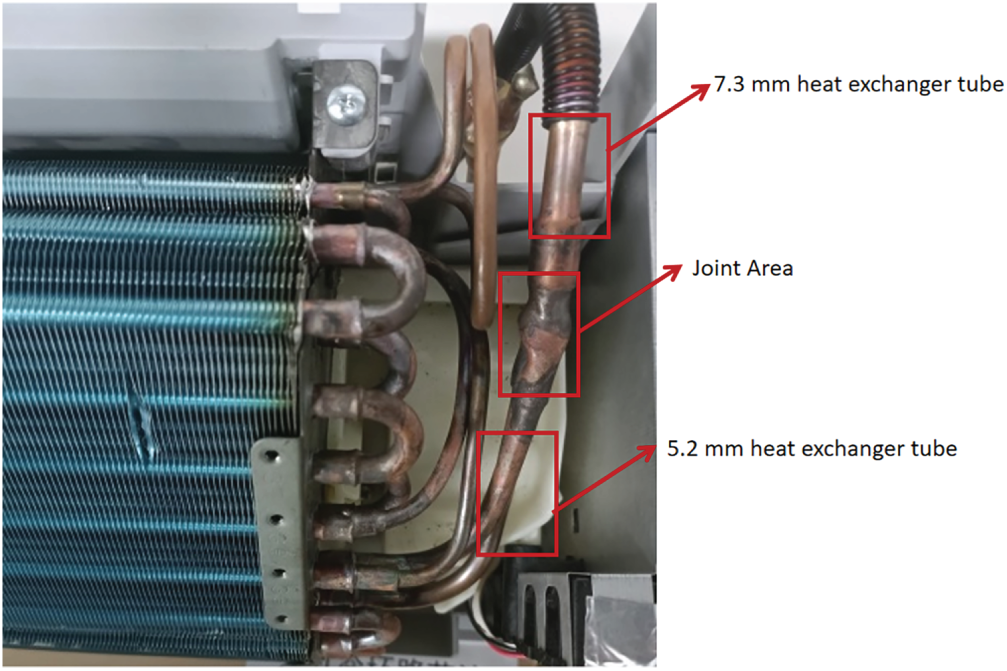
Figure 1: Variable tube diameter heat exchanger sample
This study introduces a collaborative design methodology that systematically integrates tube diameter combinations and flow path layout as coupled variables for the first time. By combining theoretical modeling with numerical simulation, the research not only identifies optimal tube diameter sequences and airflow path designs, but also quantitatively elucidates the underlying coupling mechanisms between tube arrangement and flow configuration—as well as their collective influence on the temperature field, flow field, and phase change behavior. The proposed approach is shown to significantly enhance heat transfer efficiency while incurring only a moderate increase in refrigerant-side pressure drop. Moreover, it simultaneously reduces material consumption and refrigerant charge. The systematic investigation reveals distinct synergistic interaction patterns between these previously isolated design parameters. The insights derived from this work provide general guidelines for the engineering design and optimization of high-performance finned-tube heat exchangers.
2 Theoretical Calculation of Combined Tube Diameters
Although a three-dimensional numerical simulation of the heat transfer and flow process between the refrigerant side and the outside air side of the air conditioning indoor unit (evaporator) can obtain more accurate calculation results, it requires a large amount of computation and has low computational efficiency. Therefore, theoretical calculation is used to obtain the refrigerant inlet and outlet temperatures, pressure drop, tube wall temperature and heat transfer, and to analyze the heat transfer and resistance performance of the indoor unit. It provides a calculation method for obtaining the wall temperature required for numerical simulations of the outside tube.
Currently, there is a lack of available design calculation models specifically tailored for combined tube diameter heat exchangers. To address this gap, this paper proposes theoretical design calculations for combined tube diameter heat exchangers based on traditional evaporator design calculations. A four-part iterative approach is employed using wall temperature, heat exchange, pressure drop in the tube, and pressure change at the tube expansion.
When calculating the heat exchange, the air inlet state, certain parameters are known in advance, such as the air inlet state, air volume, dryness of the refrigerant at the inlet and outlet, and the structural parameters of the fin and single tube in the heat exchanger. The parameters to be assumed include heat exchange
The difference in specific enthalpy between inlet and outlet air is Eq. (1) [22]:
where,
The enthalpy
The j-factor for the heat transfer coefficient of the air outside the tube is calculated using Eq. (2) [23]:
where,
The calculation formula for boiling heat exchange of refrigerant in micro tubes is Eq. (3) [24]:
where,
where,
The heat transfer coefficient based on the area outside the tube is Eq. (6) [25]
The average heat transfer temperature difference is Eq. (7):
where,
The calibrated heat exchange is Eq. (8) [26]:
The inner wall temperature of the tube is Eq. (9):
The outer wall temperature of the tube is Eq. (10):
where,
In the calculation,
In the heat exchanger, there is a constant flow of refrigerant in the tubes. As boiling heat exchange takes place, the dryness fraction of the refrigerant increases, leading to an increase in flow resistance and the creation of a pressure drop. The refrigerant evaporation temperature changes accordingly. There is a temperature difference between the refrigerant and the evaporation temperatures at the inlet and outlet of the heat exchanger. Therefore, using the refrigerant outlet temperature as a basis, an iterative calculation of both pressure drop and evaporating temperature can determine the range of variation of the refrigerant evaporating temperature.
Frictional pressure drop of the refrigerant in the tube is calculated using the Chisholm formula Eq. (11) [27]:
where,
The total pressure drop in the tube is calculated as Eq. (12):
where, n is the number of flows and L is the length of a single tube.
In the calculation, the outlet evaporating temperature is kept constant as a basis. The evaporating temperature of the refrigerant at the inlet needs to be assumed. After calculation, the two-phase frictional pressure drop of the refrigerant inside the tube can be obtained. The obtaining evaporating temperature at the inlet is compared with the assumed evaporating temperature, using the outlet temperature as a basis. If the error between the obtained and assumed inlet evaporation temperatures is less than 1%, the inlet evaporation temperature of the refrigerant is considered accurate. However, if the error exceeds 1%, a new assumption for the inlet evaporation temperature is necessary.
For the analysis of the pressure variation in a sudden expansion of tube diameter in a gas-liquid mixed two-phase refrigerant flow, Schmidt and Friedel [28] developed a model that considers the presence of liquid entrainment. This model allows the calculation of pressure changes in the joint area of the large and small tube diameter (Abbreviation: Joint Area). The value of the pressure change is calculated from Eq. (13):
where
where,
The temperature and pressure state following the refrigerant in the big diameter tube (Joint Area) can be determined by calculating the pressure change during the Joint Area. When calculating the pressure drop change during a Joint Area at the combined tube diameter, it is necessary to make an assumption regarding the evaporation temperature of the heat exchanger tube before the refrigerant in the small diameter tube (Joint Area). Through iterative calculations, the final evaporation temperature and evaporation pressure can be determined.
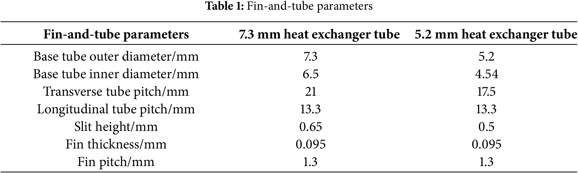
The numerical calculation model employed in this paper is adapted from the manufacturer and it is simplified from the actual structure of the indoor unit. Considering the periodic arrangement of the fins inside the indoor unit, the calculation domain for the two-fin pitch is selected to account for modeling and computational calculation. Fig. 2 shows the three-dimensional structure of the indoor unit. Fig. 3 shows the physical model of the full 7.3 mm tube diameter heat exchanger created by SolidWorks. The rotating area of the fan is defined by a diameter close to the width of impeller, with an external diameter of 102 mm and an internal diameter of 74 mm. Fig. 4 shows the fin structure corresponding to a 7.3 mm tube diameter and a 5.2 mm tube diameter heat exchanger. The fin parameters are shown in Table 1.
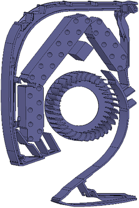
Figure 2: Three-dimensional structure of indoor units
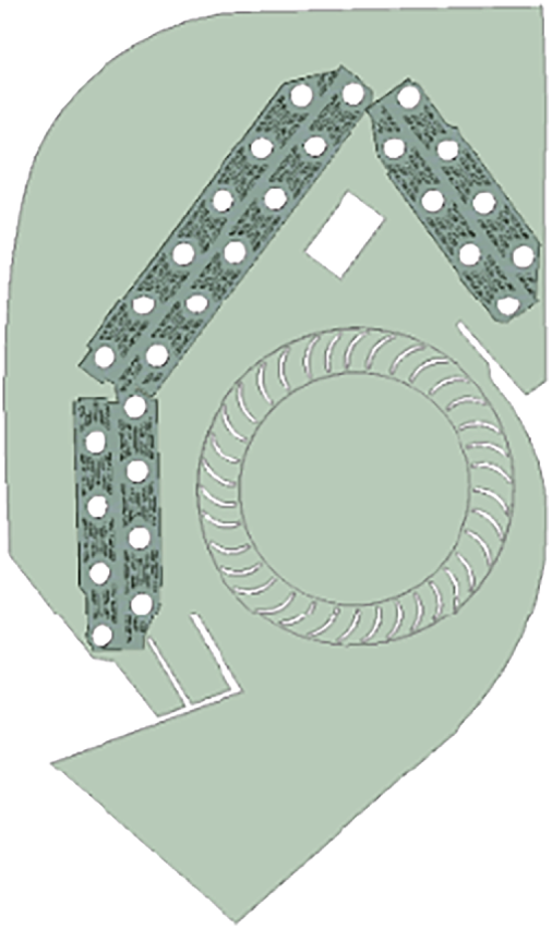
Figure 3: Physical model of the indoor unit
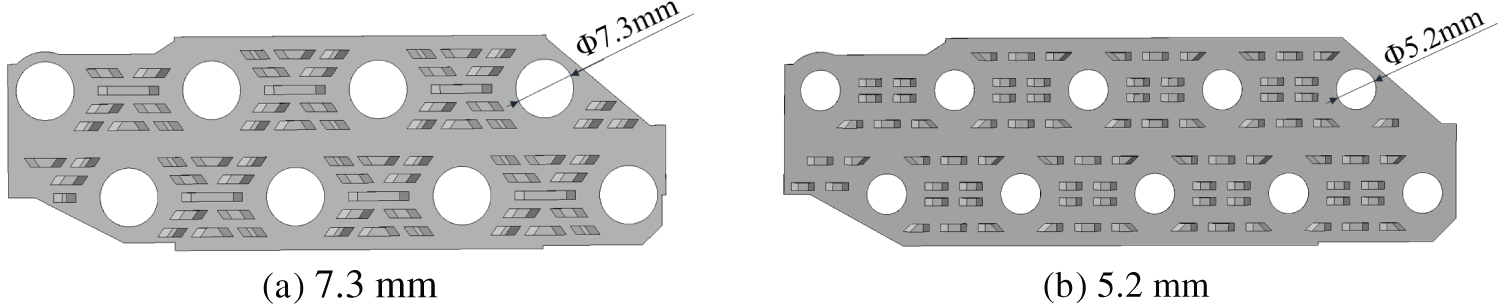
Figure 4: Heat exchanger fins
Due to the intricate nature of the indoor unit, grid refinement is necessary to ensure the accuracy calculations. The numerical simulations in this study were performed using the ANSYS Fluent 2020R2, the pre-processing software Fluent Meshing of Fluent 2020R2 is utilized to generate a mesh for the indoor unit of the air conditioner, encompassing internal fins, fans, impellers, and other components. This software is capable of producing polyhedron Hexahedron meshes (Poly Hexcore). The advantageous characteristic of this type of mesh is its ability to generate a smaller number of meshes. A steady-state solver configuration was employed. The solution was considered converged when the residuals for all governing equations fell below the software’s default criteria and the outlet temperature stabilized,while maintaining high quality, facilitating convenient convergence during calculations. As shown in Fig. 5, certain sections of the turbine impeller rotate simulation demanding high-quality meshing for these moving regions. Therefore, the impeller rotation area and the internal area of the fan are subjected to grid refinement. Grid refinement is implemented for the finned tubes due to the heat transfer occurring between solids, the convective heat transfer between the air and the finned surfaces, and the small thickness of the fins. To ensure the simulation accuracy, three boundary layer meshes are established in areas where velocity boundary layers, including the walls and each impeller surface.
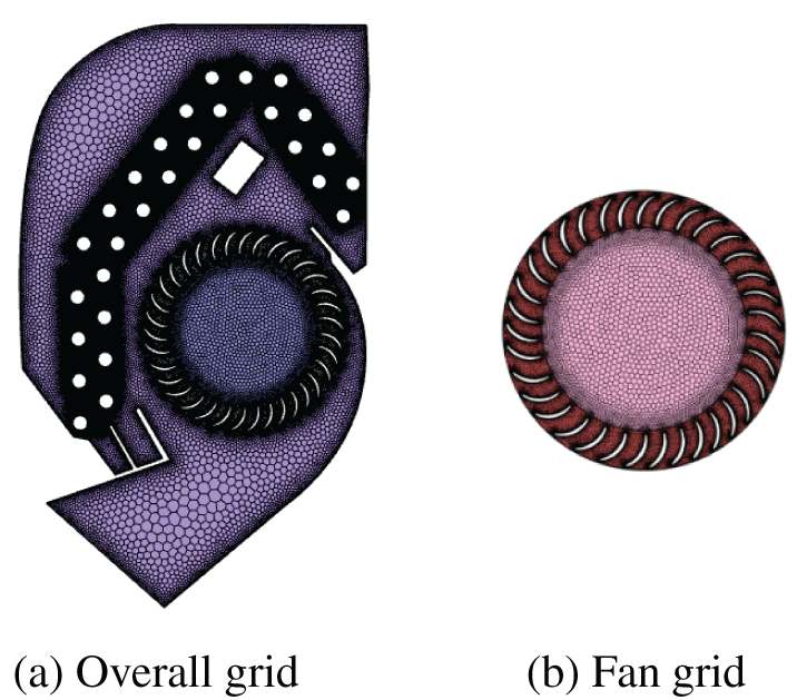
Figure 5: Grid division
Based on the actual working conditions, several assumptions are made regarding the physical model of the air conditioning indoor unit during the numerical simulations conducted in this paper. These assumptions include: Negligible radiant heat transfer; Low air flow rate and density; Air is considered as a constant incompressible fluid; Non-slip boundary condition is applied to the model wall; Fouling thermal resistance is neglected; Contact thermal resistance between the fins and the tube wall is ignored, and the temperature at the root of the fins is assumed to be equal to the tube wall temperature.
As shown in Fig. 6, the computational model in this study employs the following boundary conditions: A pressure-inlet condition is applied at the inlet, with total pressure set to atmospheric pressure. The outlet is modeled using a pressure-outlet condition, which may induce backflow. However, since the primary focus of this study is on the heat transfer characteristics in the finned-tube region and the temperature measurement plane is located downstream of the fan, backflow does not compromise the validity of the core findings. For wall boundaries, the heat exchanger tube walls are assigned a fixed temperature condition, while all other walls are treated as adiabatic. Given the periodic nature of the fin array in the computational domain, periodic boundary conditions are imposed on the front and rear surfaces of the model.
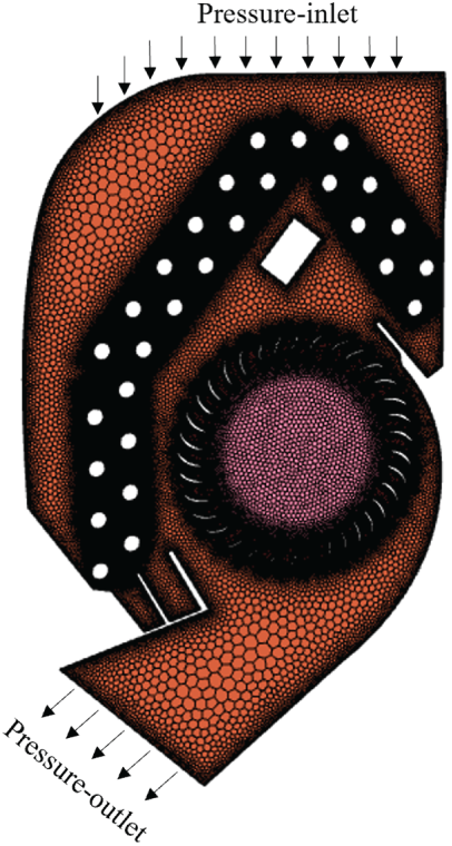
Figure 6: Inlet and outlet boundary conditions
When the indoor unit is in operation, the impeller rotation zone undergoes a specific speed of rotation, rendering it a moving area. The heat exchange zone remains relatively stationary within the circular zone inside the fan, representing a static zone. The interaction between dynamic and static regions is a non-negligible challenge during numerical calculations. In this study, the MRF (Multiple Reference Frame) model is employed for the impeller rotation zone. It means that the impeller rotation zone is defined as Frame Motion, and the impeller wall is designated as Moving Wall, which remains stationary relative to the impeller rotation zone.
3.3 Solution Method and Governing Equation
In this study, the flow and heat transfer condition of a three-dimensional, constant, incompressible fluid is simulated. The pressure-based solver is selected to solve the governing equations. The Standard k-ε turbulence model is employed to capture the turbulence characteristics. The SIMPLE algorithm is chosen for pressure-velocity interaction. The discretization of momentum, turbulent kinetic energy, and turbulent dissipation rates in the control equations is performed using a second-order windward format. Furthermore, the physical parameters of the refrigerants used in the calculations are obtained from the software Refprop 9.1.
The air flow follows the equations of continuity, momentum and energy. The mathematical depiction of fluid motion by the three conservative laws constitutes the basic set of equations for fluid dynamics. The flow heat transfer problem is solved by solving the equations for conservation of mass, momentum and energy [29].
(1) Continuity equation
The equation of continuity, based on the law of conservation of mass and using the micro-element assumption is Eq. (15):
where,
(2) Momentum equation
Base on the principle of conservation of momentum, the differential form of the momentum conservation equation is obtained after using the microelement assumption to establish the momentum equation and introducing the concept of tensor:
where, P is the pressure,
(3) Energy equation
The differential form of the conservation of energy equation is Eq. (19):
where, T is the thermodynamic temperature,
3.4 Grid-Independent Validation
When conducting numerical simulations, the quality of the mesh has a significant impact on the accuracy of the results. In this study, the numerical simulation of an indoor unit model with all 7.3 mm external diameter heat exchanger tubes was performed using five different mesh sizes ranging from 6.1 to 10.1 M. The calculated results are shown in Fig. 7. It can be observed that the error in the heat exchanger calculations for both the 9.1 and 10.1 M meshes was below 0.2%. Consequently, the 9 M mesh can be considered as a grid-independent solution, exhibiting sufficient accuracy. The subsequent calculations will employ a mesh size of 9.1 M.
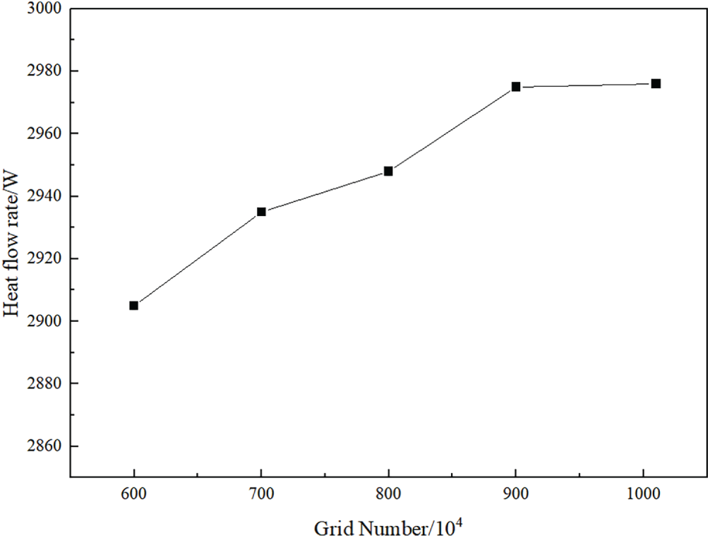
Figure 7: Simulation of heat exchange and number of grids
3.5 Experiment and Model Validation
3.5.1 Experimental Setup and Procedure
A standardized air enthalpy difference laboratory was employed to conduct this experiment, which aimed at a precise evaluation of the thermal performance of an indoor air conditioner heat exchanger. The laboratory configuration includes thermally insulated indoor and outdoor chambers, facilitating independent and precise climatic control on each side. Installed in the indoor chamber per standard requirements was the test subject—a split-type indoor air conditioner unit featuring a 7.3 mm diameter heat exchanger.
The experimental setup incorporated the following high-precision measurement systems: Air Conditioning Treatment System: Stabilizes the indoor dry-bulb and wet-bulb temperatures within tolerances of ±0.2°C and ±0.1°C, respectively. Temperature and Humidity Sampling System: Employs dedicated sensors for monitoring the dry-bulb and wet-bulb temperatures of both the intake and exhaust air streams. Airflow Measurement System: Quantifies the volumetric airflow using a vane anemometer. Refrigerant Parameter Measurement System: Tracks refrigerant temperature via platinum resistance thermometers embedded in the pipelines and directly acquires the refrigerant pressure difference across the heat exchanger using high-precision differential pressure sensors.
The experiment strictly followed steady-state testing protocols. Formal data acquisition was initiated after the system achieved a stable state, characterized by the outlet temperature of the indoor unit varying within a predefined threshold for a continuous 30-min period. The air enthalpy difference method constituted the core calculation: the specific enthalpy of air was deduced from the measured dry-bulb and wet-bulb temperatures; subsequently, this was combined with the mass airflow rate—calculated from the measured volumetric airflow and prevailing air properties—to determine the final heat exchange capacity of the indoor heat exchanger.
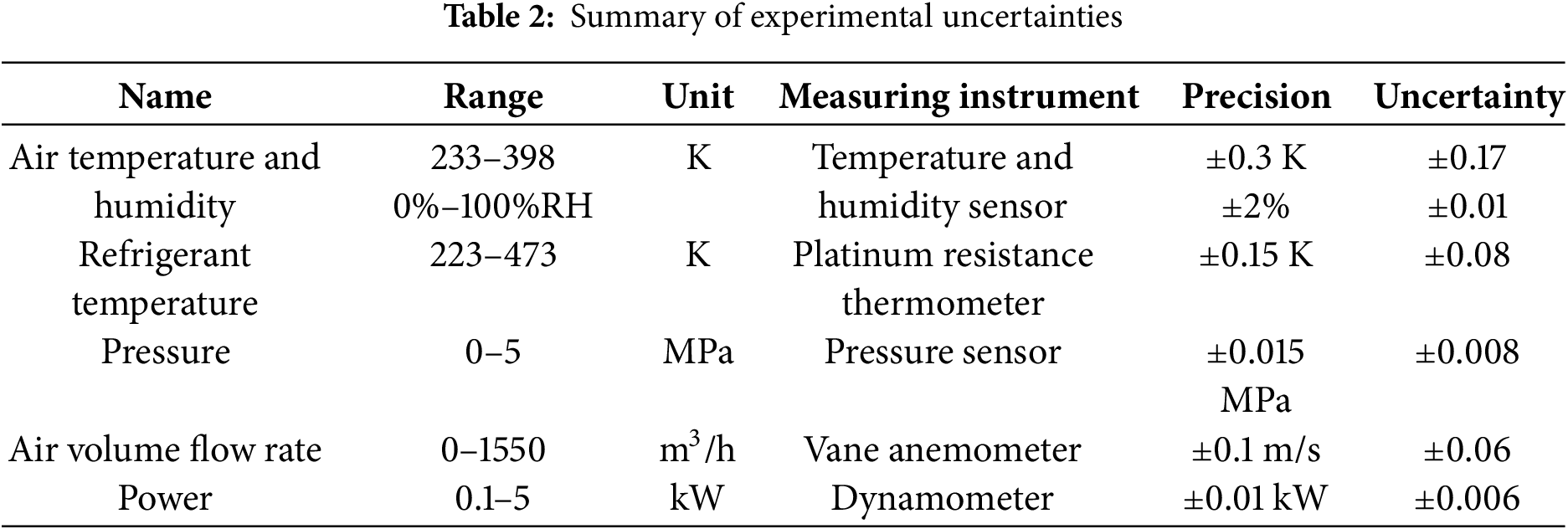
In accordance with the GUM guidelines, an uncertainty analysis was undertaken to assess measurement reliability. Table 2 enumerates the standard uncertainties associated with each direct measurement. The uncertainty of different variables in this experiment can be calculated from Formula (20) (Moffat, 1988) [30]. Therefore, the uncertainty of the heat change is 5.76%, attesting to the engineering accuracy and reliability of the experimental findings.
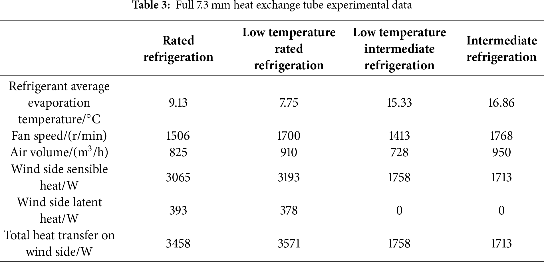
The experimental measurements of air volume and heat exchange were conducted for a full 7.3 mm diameter heat exchanger tube air conditioner under both nominal cooling and low temperature cooling conditions. The results of these measurements are shown in Table 3.
To verify the reliability of the numerical model, we compared the simulation results with experimental data, focusing on the sensible heat transfer under different wind volumes. The simulations results for the full 7.3 mm heat exchanger tube indoor unit under different various operating conditions using the previous simulation calculation are shown in Table 4. The apparent heat obtained from the simulated data in Table 4 was compared with the apparent heat derived from the experimental data presented in Table 3. The comparison results are shown in Fig. 8. The maximum error between simulation results and experimental results is 5.27% (operating point of 950 m3/h). This error was relatively small and fell within an acceptable range. Therefore, the numerical simulation method employed in this study was deemed accurate and suitable for subsequent optimization design calculations.
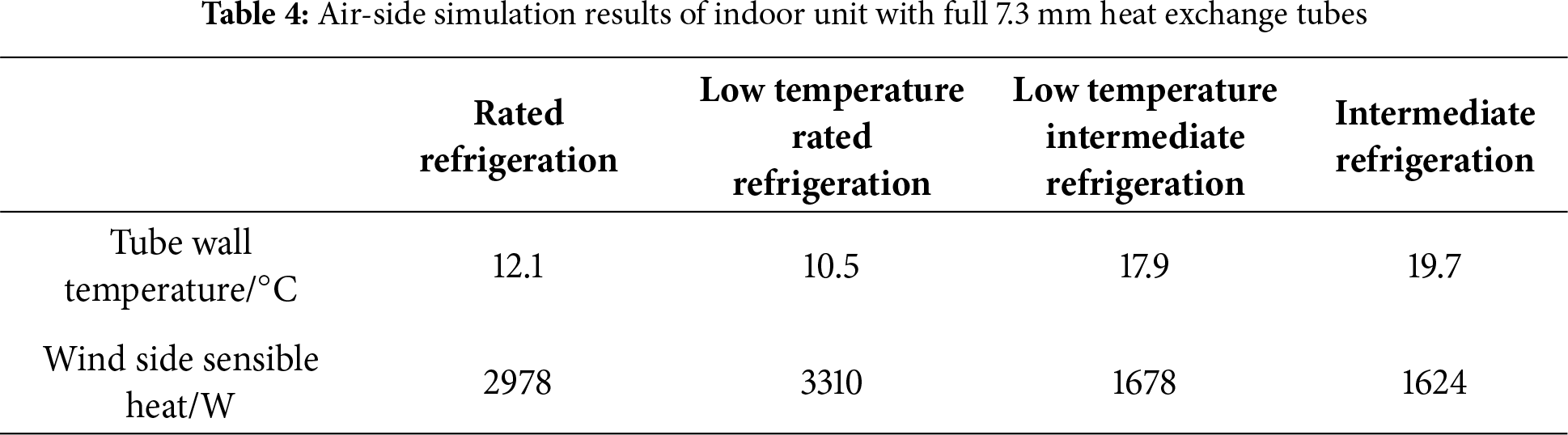
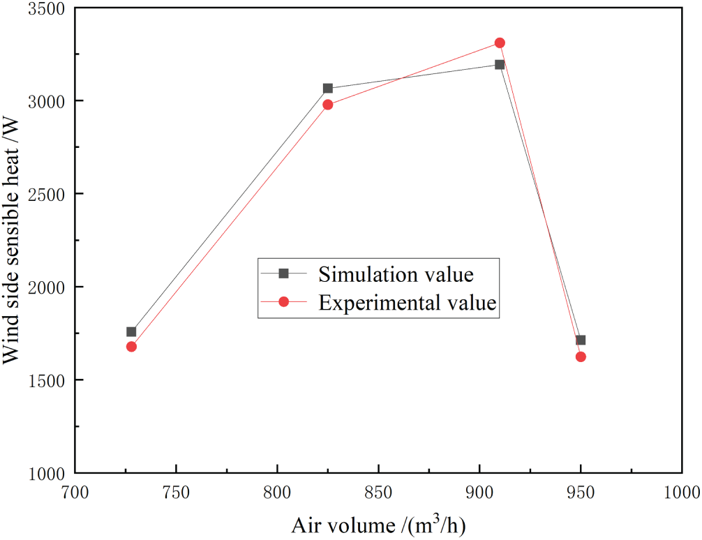
Figure 8: Comparison of experimental and simulated heat calculation heat
4.1 Combined Tube Diameter Flow Path Design
The indoor units utilized in the experiments were all equipped with 7.3 mm tube diameters, serving as the baseline solution for comparison with the combined tube diameter approach. The tube bundle within the indoor unit consisted of two rows, which was further divided into two plates: the large tube plate and the small tube plate.
A total of three different combinations of heat exchanger tube arrangements are proposed in this paper. Different flow paths are designed for each scheme. Eight flow paths have been designed in total. The allocation of heat exchanger tubes and flow paths for each scheme is shown in Table 5. The flow paths for each scheme are shown in Fig. 9. As an example of scheme IA flow path assignment, shown in Fig. 9a, the blue part represents flow path I and the red part represents flow path II. (In subsequent schemes, flow path I is marked in blue, flow path II in red and flow path III in green.) The refrigerant in flow path I enters at point 1 on the outside of the small tube plate, traverses along the outside of the small tube plate through four flows, then proceeds to the large tube plate through ten flows, and finally exits the heat exchanger at point 2.
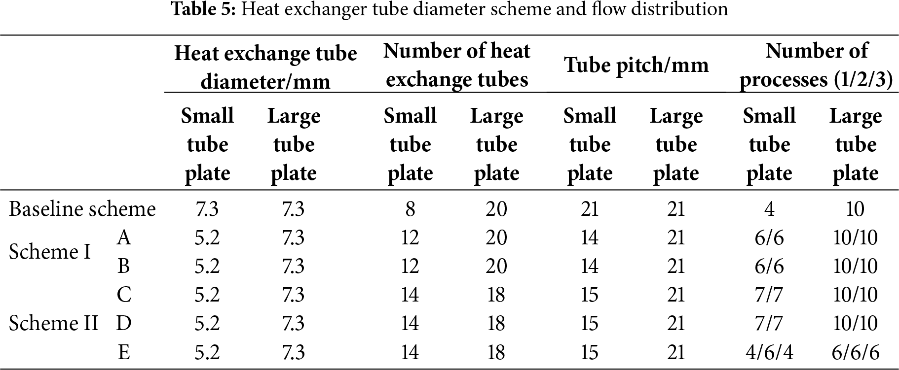
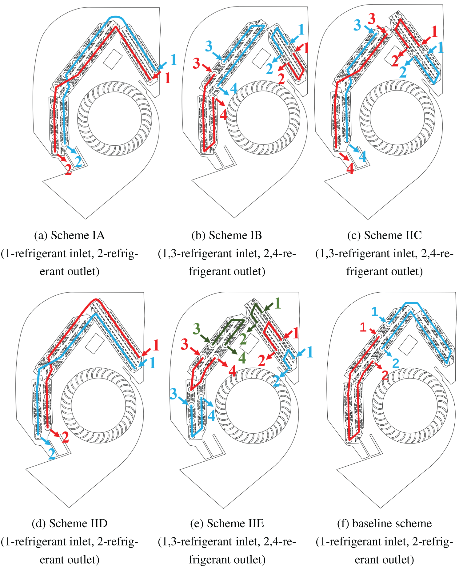
Figure 9: Flow path design (Flow path I in blue, flow path II in red and flow path III in green)
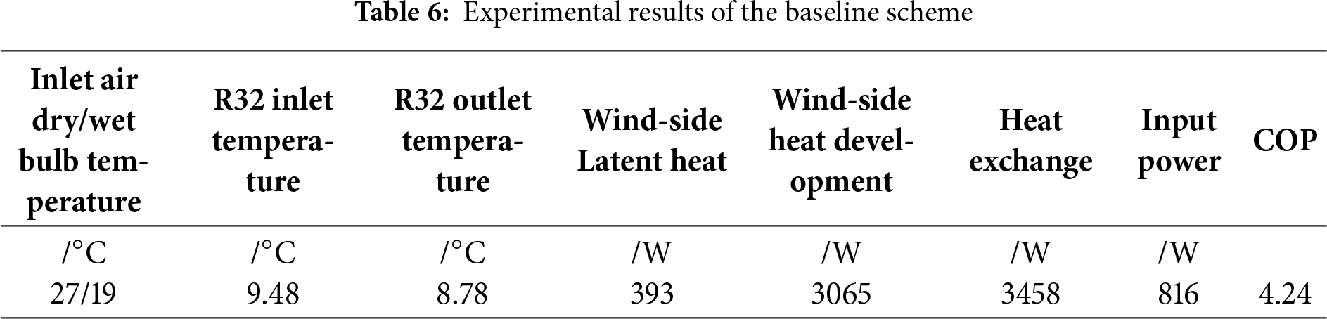
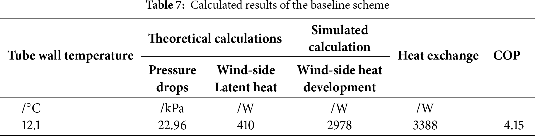
To establish a baseline for comparing the heat transfer performance of combined tube diameter heat exchangers, the first step involved conducting numerical simulations for a complete heat exchanger with a 7.3 mm tube diameter. The flow path distribution for the full 7.3 mm tube diameter heat exchanger is shown in Fig. 9f. Experimental data for an air condition system with a full 7.3 mm diameter heat exchanger tube using R32 under nominal cooling conditions are shown in Table 6. The calculated tube wall temperature was determined to be 12.1°C, with a latent heat of 410 W on the wind side. In this case, the compressor input power was assumed to be 816 W for all the later COP calculations, as the calculations for each combined tube diameter scheme were based on the same refrigerant outlet temperature and the flow rate as the baseline scheme. It can be seen from Tables 6 and 7 that the error between the calculated latent heat and the experimentally measured latent heat is 4.33%. The air volume shows an error of 2.02%, while the pressure drop shows an error of 0.7%. Additionally, the simulated apparent heat on the wind side displays an error of 2.84% when compared to the experimentally values. These results demonstrate the reliability of the simulation.
4.3 Heat Transfer and Flow Pressure Drop Performance Analysis
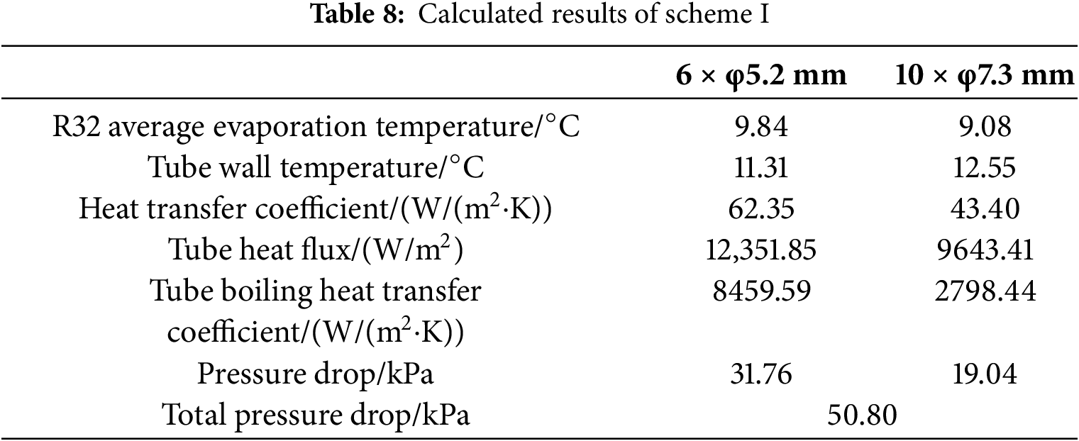
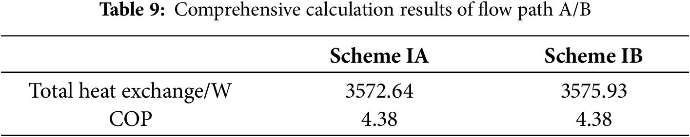
The calculation results for each flow path of the combined tube diameter heat exchanger scheme I are shown in Tables 8 and 9. It can be observed that the total heat exchange for the different flow path design schemes IA and IB exhibits an increase of 5.45% and 5.55%, when compared to the baseline scheme. Moreover, the corresponding COP values also show improvement, increasing from 4.15 to 4.38, as shown in Table 9.
Compared to the baseline scheme, there is a noticeable increase of 12.15% in the overall external heat transfer area of the small tube plate. The comparison of the velocity cloud graphs and the heat transfer coefficient cloud graphs of the fin surfaces in the marked area is shown in Figs. 10 and 11 showcasing the differences among the baseline scheme, scheme IA. Scheme IA and IB velocity and heat transfer coefficient cloud graphs are shown in Figs. 12 and 13.
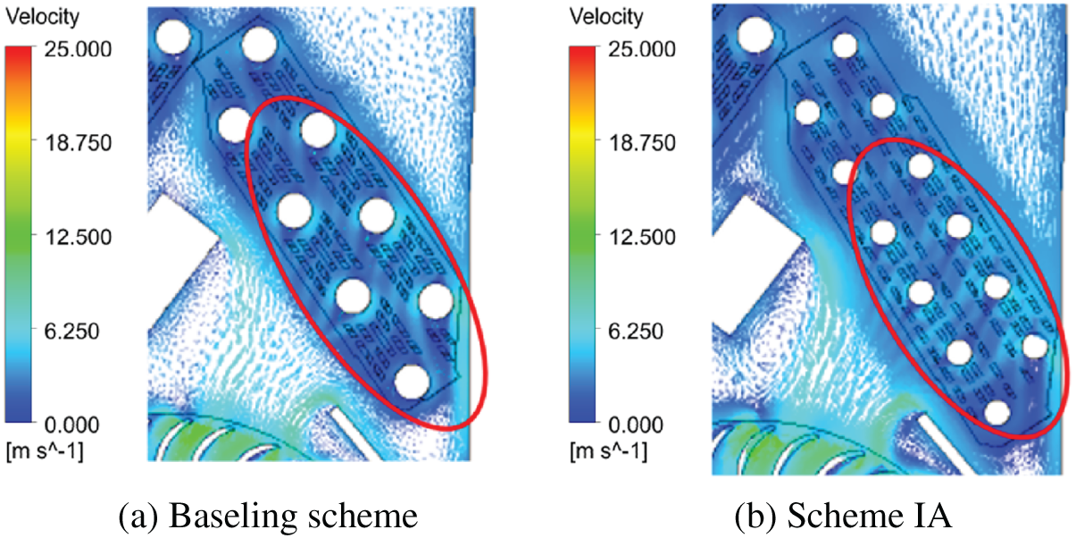
Figure 10: Baseline scheme and scheme IA marked area velocity vector cloud image details comparison
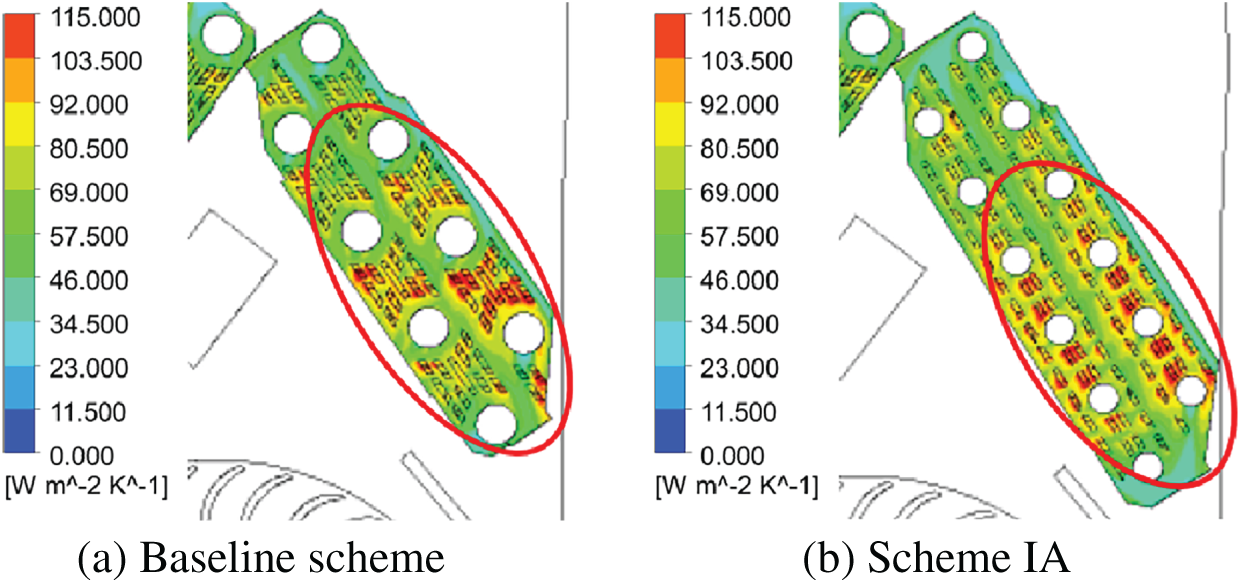
Figure 11: Baseline scheme and scheme IA marked area surface heat transfer coefficient cloud map details comparison
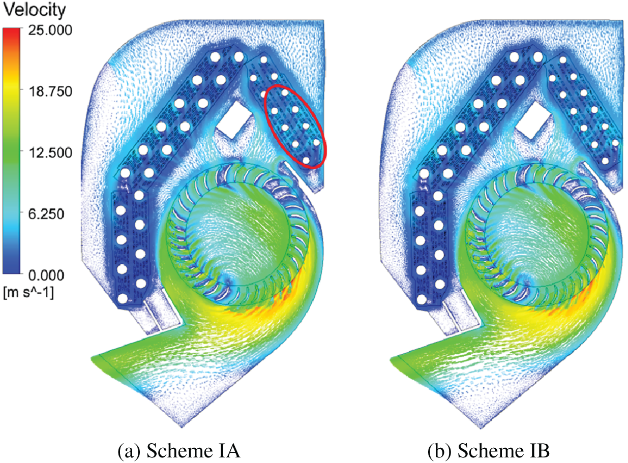
Figure 12: Scheme IA, IB velocity vector
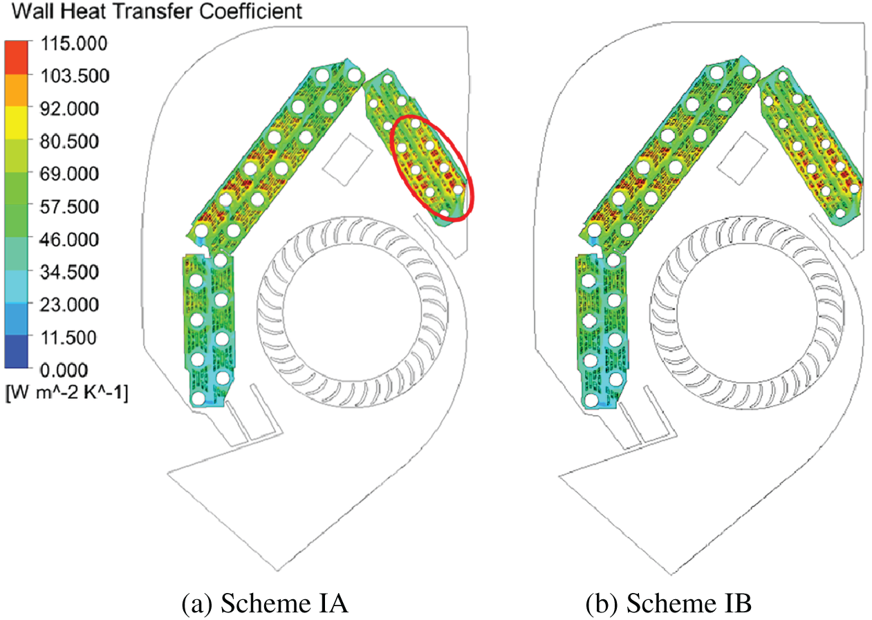
Figure 13: Scheme IA, IB heat transfer coefficient
The increase in heat transfer capacity observed in scheme I is attributed to two main factors. On the one hand, Although the average temperature of the wall in the small tube plate section increases, the overall air resistance of the small tube plate remains low, enabling high airflow. The variation in airflow plays a crucial role in enhancing heat transfer. On the other hand, the inclusion of eight 5.2 mm heat transfer tubes within the marked area, compared to the base scheme, increases both the number of heat transfer tubes and the total heat transfer area outside the tubes. This factor further contributes to the improved heat transfer capacity of scheme I. The combined effect of these first two factors offsets the potential heat transfer deterioration caused by the increase in tube wall temperature, resulting in an overall improvement in the heat transfer performance of scheme I. Although the flow path design of scheme IA and IB are different, the number of heat transfer tubes allocated within a single flow path remains the same. The average tube wall temperature in the corresponding area of the tube plate is consistent for both schemes, resulting in comparable heat transfer capacities.
For the refrigerant side of the tube, the flow path I initially passes through the 5.2 mm heat exchanger tube. In this section, the dryness of the refrigerant is in relatively low. The flow pattern consists of bubbly and slug flow, with nuclear boiling as the dominant form of heat transfer. As the flow rate increases, the heat transfer between the working fluid and the wall intensifies. The number of cores producing gasification is increased, leading to an enhanced heat flux. In the latter half of the 7.3 mm heat exchanger tube, the flow pattern transitions from nucleate boiling to a liquid film convection boiling zone. The liquid film spreads over the tube wall. There is in extensive contact between the gasification core and the liquid film. This weakens the boiling heat exchange process. When R32 becomes part of the spray stream, the majority of the gas phase R32 comes into contact with the tube wall, resulting in a significant reduction in the boiling heat transfer coefficient in the latter half of the tube.
Compared to the baseline scheme, in scheme I, the number of small diameter heat transfer tubes in the single flow path of the small plate section increases, and the heat exchange area inside the tubes increases. In addition, the increased mass flow rate of R32 enhances the heat exchange with the wall, thereby increasing the heat flux and boiling heat transfer coefficient inside the small tube plate section. After absorbing more heat in the small tube plate, R32 enters the large tube plate, where its dryness fraction increases, suppressing the boiling heat transfer effect. The higher wind speed of scheme I in the marked area can be clearly seen in Fig. 10. The proximity of the marked area to the fan and the absence of obstructive structures contribute to the increased wind speed, thereby enhancing heat transfer. Therefore, the fins in the marked area demonstrate a high heat exchange capacity. the cloud graph of the convective heat transfer coefficients between the air and fin surfaces is shown in Fig. 11. It reveals that the marked areas exhibit the highest convective heat transfer coefficients, while the other areas show lower values. The overall increase in total surface area outside the tube and the higher air velocity enhance heat transfer to a greater extent than the deterioration caused by the increase in tube wall temperature. Therefore, the boiling heat transfer coefficient is stronger than that of the baseline scheme.
The pressure drops in the tube, which indicate the resistance encountered by the refrigerant flow, are essential factor to consider when studying flow characteristics inside the tube. Compared to the baseline scheme, scheme I exhibits a notable increase in pressure drop primarily in the small tube plate section. This is attributed to the significantly reduction in tube diameter, which leads to a substantial increase in the mass flow rate of R32. The higher mass flow rate results in an overall increase in the flow rate of the R32 two-phase mixture, resulting in an elevation in frictional pressure drop. Based on the previous analysis of heat transfer and pressure drop characteristics, it can be concluded that both schemes IA and IB exhibit improved coefficient of the COP compared to the baseline scheme.
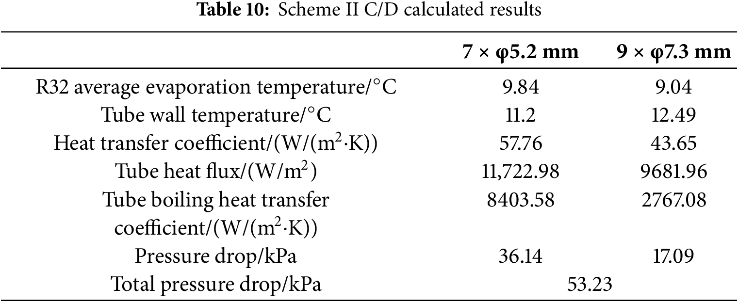
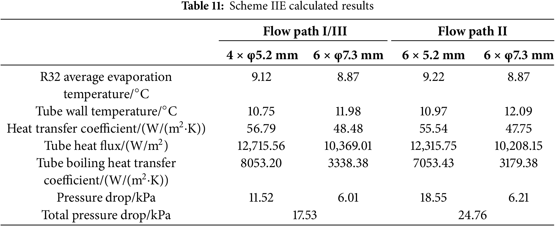
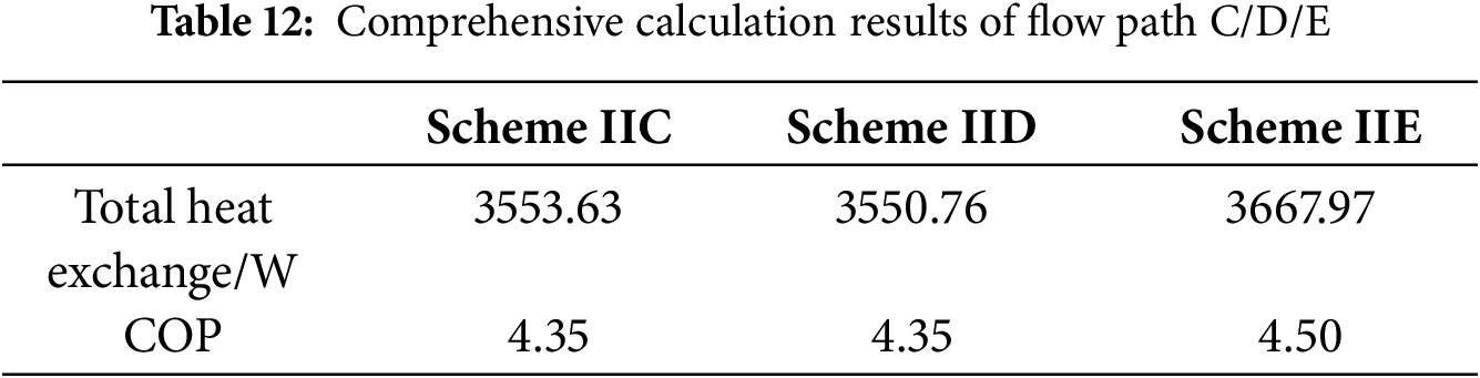
Scheme IIC and IID consists of the same number of small and large bunches, but they differ in terms of the distribution of flow paths. The calculated results for both schemes are presented in Table 10. Scheme IIE is divided into three separate flow paths, and the corresponding calculation results are presented in Table 11. The heat exchange performances of the different schemes are presented in Table 12. Schemes IIC, IID and IIE exhibit heat exchange enhancements of 4.89%, 4.8% and 8.26% respectively, compared to the baseline scheme. And the COP increased to 4.35, 4.35 and 4.5 for schemes IIC, IID and IIE, respectively.
Compared to the Baseline scheme, scheme I, scheme II has an increase in the heat transfer area outside the small tube plate and a decrease in the heat transfer area outside the large tube plate, respectively. The velocity vector and the heat transfer coefficient of scheme IIC and IIE are showed in Figs. 14 and 15.
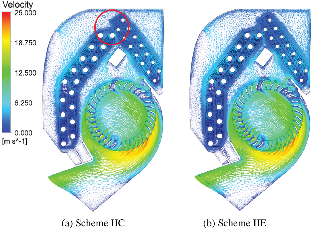
Figure 14: Scheme IIC, IIE velocity vector
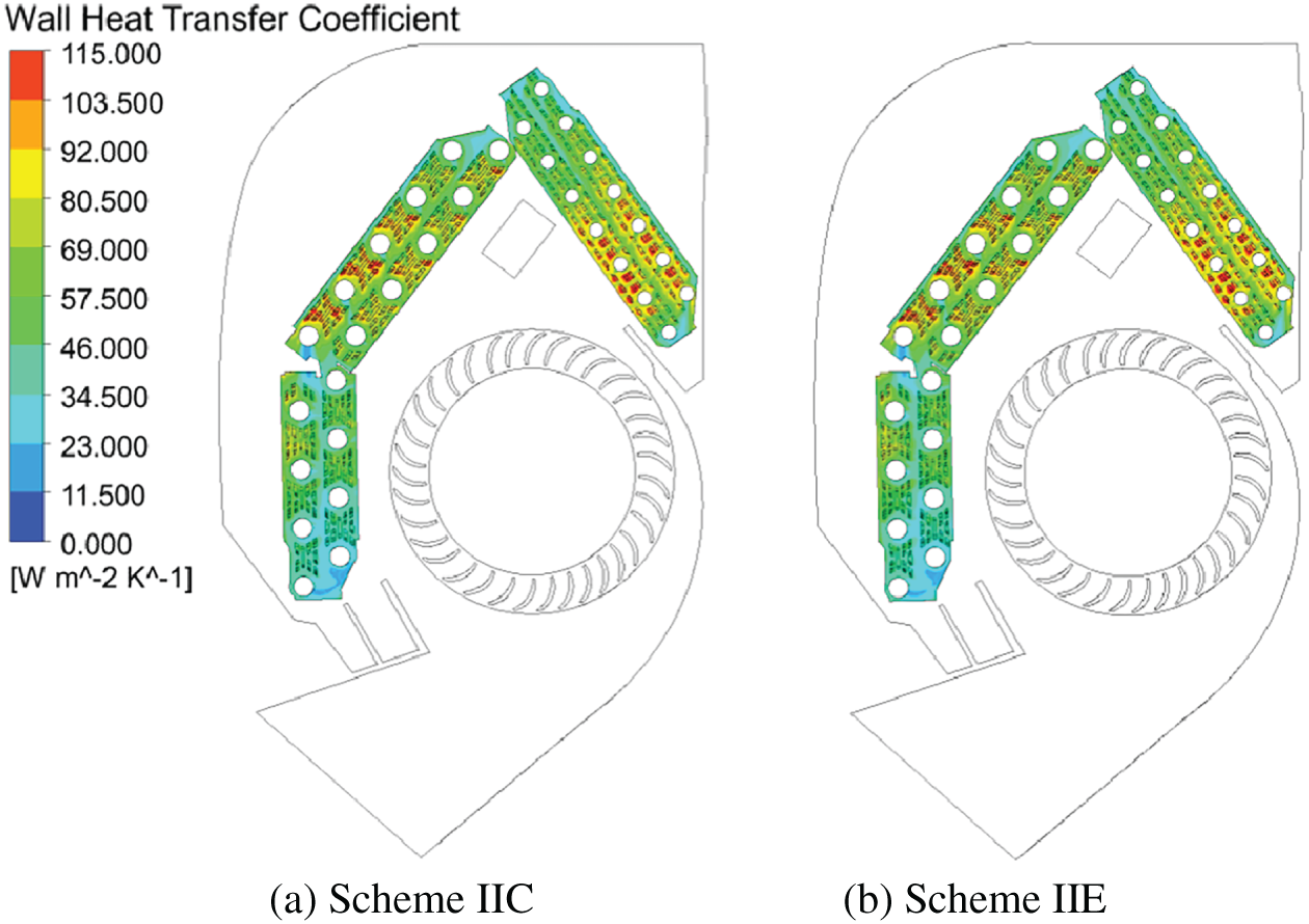
Figure 15: Scheme IIC, IIE heat transfer coefficient
Scheme II is the same as scheme I in terms of enhanced heat transfer performance outside of the tubes. The deterioration of the heat transfer effect caused by a reduced temperature difference between the tube wall and the air is offset by the increased air volume and area. Scheme IIE has three flow paths, with one path exhibiting a small pressure drop and a low average evaporation temperature. As a result, the tube wall temperature is lower compared to the previous schemes, resulting in a significantly improved heat transfer effect surpassing all previous schemes.
In scheme II, it is notable that the small plate section contains the highest number of 5.2 mm heat transfer tubes compared to other combined tube diameter schemes. This configuration results in a larger heat transfer area within the tubes. Therefore, the mass flow rate of R32 in the 5.2 mm heat exchanger tube increases, leading to an enhancement in heat transfer. As a consequence, the boiling heat transfer coefficient within the tubes of scheme II is significantly greater than that of baseline scheme. The factors for the suppression of boiling heat transfer in the large tube plate section of the tube is similar to schemes I.
The small plate section of Scheme IIC and IID incorporates the highest number of 5.2 mm heat exchanger tubes, resulting in a substantial increase in pressure drop compared to combined tube diameter schemes. The average temperature inside the tube is higher than that of the baseline scheme. Despite modifications to the tube plate structure in scheme II, which result in an increase in pressure drop within the small tube plate section and a decrease in pressure drop within the large tube plate section, the heat transfer performance of schemes IIC and IID exhibits significant improvement when compared to the baseline scheme, considering only two flow paths. However, it is worth noting that the COP improvement achieved by these schemes is not as pronounced as that of scheme I. The design of scheme IIE with three flow paths reduces the mass flow rate of R32 within each individual flow path. This reduction subsequently lowers the overall flow rate of the two-phase mixture inside the tube, effectively reducing the pressure drop within the system. Consequently, this reduction in pressure drop results in lower average evaporation temperature and tube wall temperature for R32. These modifications contribute to a substantial increase in the COP of scheme IIE.
The main purpose of the paper is to propose a novel heat exchanger configuration that combines both large and small diameter heat exchange tubes. Various combinations of tube diameters and flow path design schemes were designed and analyzed to determine the optimal configuration. The main conclusions are as follows:
(1) A novel calculation model for variable tube diameter was proposed in this study, utilizing the refrigerant outlet temperature as the reference point. The final results of various parameters were obtained through iterative calculations.
(2) Based on experimental data of the indoor unit heat exchanger, a numerical simulation calculation model was established as the baseline scheme. The reliability of the calculation model was validated by comparing the simulation results with experimental data.
(3) Three different combinations of tube diameters and eight different flow path designs were proposed in this study to investigate the pressure drop and heat transfer characteristic of the heat exchanger. Each tube diameter combination scheme exhibited an enhanced heat transfer capacity ranging from 2.79%~8.26% compared to the baseline scheme, and an increased COP ranging from 4.15 to 4.27~4.5. The results show that scheme IIIH is the optimal combination of tube diameter and flow path design for R32, effectively balancing heat transfer performance and economic considerations.
Acknowledgement: The authors would like to thank the School of Mechanical and Electrical Engineering, Zhoukou Normal University for their support.
Funding Statement: This work is supported by Supported by the Scientific Research Foundation for High-Level Talents of Zhoukou Normal University (ZKNUC2024018).
Author Contributions: Conceptualization, Zheming Cheng and Xinping OuYang; Methodology, Zheming Cheng; Software, Zheming Cheng; Validation, Zheming Cheng, Xinping OuYang, and Zihao Wang; Form alanalysis, Zheming Cheng; Investigation, Zheming Cheng; Resources, Xinping OuYang and Ke Sun; Datacuration, Zheming Cheng; Writing—original draft preparation, Zheming Cheng and Zihao Wang; Writing—review and editing, Zheming Cheng and Ke Sun; Visualization, Zheming Cheng; Supervision, Xinping OuYang and Leren Tao; Funding acquisition, Zheming Cheng and Xinping OuYang. All authors reviewed the results and approved the final version of the manuscript.
Availability of Data and Materials: The data that support the findings of this study are available from the corresponding author upon reasonable request.
Ethics Approval: Not applicable.
Conflicts of Interest: The authors declare no conflicts of interest to report regarding the present study.
Nomenclature
| Specific heat capacity (J/(kg∙K)) | |
| Fin root diameter (mm) | |
| Inner diameter of the tube (mm) | |
| dw | Humidity |
| F | Volume force (N) |
| Unit mass velocity (kg/s) | |
| hw | Enthalpy (kJ) |
| Heat transfer coefficient (W/(m2∙K)) | |
| l | Tube length (mm) |
| Refrigerant mass flow rate (kg/s) | |
| N | Rows of heat exchanger tube |
| n | Number of flows |
| P | Pressure (kPa) |
| Evaporating pressure (kPa) | |
| Heat exchange (W) | |
| Sumed heat exchange (W) | |
| qi | Heat flux (W/m2) |
| qva | Air Volume Flow Rate (m3/h) |
| r | External thermal resistance (m2∙K/W) |
| r0 | Latent heat of evaporation (kJ) |
| Fin pitch (mm) | |
| Open slit height (mm) | |
| Open slit width (mm) | |
| Viscous dissipation term | |
| T | Thermodynamic temperature (°C) |
| t | Time (s) |
| Average heat transfer temperature (°C) | |
| Tube wall temperature (°C) | |
| Velocity vector | |
| Average dryness | |
| Two-phase fluid mixture dryness | |
| Performance coefficient | |
| Specific volume of wet air | |
| Fin thickness (mm) | |
| w | Relative humidity |
| Liquid and vapor density (g/cm3) | |
| Liquid Planter number | |
| Heat transfer coefficient (W/(m2∙K)) | |
| Dynamic viscosity | |
| Liquid Reynolds number | |
| Surface tension (mN/m) | |
| Convective heat transfer coefficient (W/(m2∙K)) | |
| Thermal conductivity (W/m∙K) | |
| Liquid thickness and fin height ratio | |
| Ratio of cross-sectional area | |
| Pressure drop gradient | |
| Two-phase flow factor | |
| Empirical coefficient | |
| Viscous stress | |
| Fluid heat transfer coefficient (W/(m2∙K)) | |
| Fluid density (g/cm3) | |
| Hamiltonian operator |
References
1. Taheri S, Hosseini P, Razban A. Model predictive control of heating, ventilation, and air conditioning (HVAC) systems: a state-of-the-art review. J Build Eng. 2022;60:105067. doi:10.1016/j.jobe.2022.105067. [Google Scholar] [CrossRef]
2. Shih YC, Tamilarasan S, Chen PH, Tsao CC, Lin CH. Optimal thermohydraulic design of the indoor unit of a split-type air conditioner. Appl Therm Eng. 2022;211:118502. doi:10.1016/j.applthermaleng.2022.118502. [Google Scholar] [CrossRef]
3. Liu N, Lai XL, Yan K, Zhang H. Investigation of flow and heat transfer characteristics on different heat exchangers of air conditioner. Appl Therm Eng. 2016;103:428–33. doi:10.1016/j.applthermaleng.2016.04.084. [Google Scholar] [CrossRef]
4. Zou T, Zhan D, Hu X, Hu S, Li Y. Experimental and numerical study of cross-flow fan in air-conditioner indoor unit. Int J Refrig. 2022;141:102–11. doi:10.1016/j.ijrefrig.2022.05.020. [Google Scholar] [CrossRef]
5. Tsao CC, Shih YC, Lin CH, Chao LY, Hu SC. Thermohydraulic and condensing phase-change analysis within the indoor unit of a split-type air-conditioner. Case Stud Therm Eng. 2020;21:100714. doi:10.1016/j.csite.2020.100714. [Google Scholar] [CrossRef]
6. D.Souza P, Biswas D, Deshmukh SP. Air side performance of tube bank of an evaporator in a window air-conditioner by CFD simulation with different circular tubes with uniform transverse pitch variation. Int J Thermofluids. 2020;3–4:100028. doi:10.1016/j.ijft.2020.100028. [Google Scholar] [CrossRef]
7. Yaïci W, Ghorab M, Entchev E. 3D CFD study of the effect of inlet air flow maldistribution on plate-fin-tube heat exchanger design and thermal-hydraulic performance. Int J Heat Mass Transf. 2016;101:527–41. doi:10.1016/j.ijheatmasstransfer.2016.05.063. [Google Scholar] [CrossRef]
8. Jige D, Sagawa K, Inoue N. Effect of tube diameter on boiling heat transfer and flow characteristic of refrigerant R32 in horizontal small-diameter tubes. Int J Refrig. 2017;76:206–18. doi:10.1016/j.ijrefrig.2017.02.012. [Google Scholar] [CrossRef]
9. Jige D, Inoue N. Flow boiling heat transfer and pressure drop of R32 inside 2.1 mm, 2.6 mm and 3.1 mm microfin tubes. Int J Heat Mass Transf. 2019;134:566–73. doi:10.1016/j.ijheatmasstransfer.2019.01.027. [Google Scholar] [CrossRef]
10. Jige D, Sagawa K, Iizuka S, Inoue N. Boiling heat transfer and flow characteristic of R32 inside a horizontal small-diameter microfin tube. Int J Refrig. 2018;95:73–82. doi:10.1016/j.ijrefrig.2018.08.019. [Google Scholar] [CrossRef]
11. He G, Liu F, Cai D, Jiang J. Experimental investigation on flow boiling heat transfer performance of a new near azeotropic refrigerant mixture R290/R32 in horizontal tubes. Int J Heat Mass Transf. 2016;102:561–73. doi:10.1016/j.ijheatmasstransfer.2016.06.074. [Google Scholar] [CrossRef]
12. Wu J, Tang Z, Zhu Y, Li X, Wang H, Shi Q. Two-phase secondary flow characteristics and heat transfer mechanism during boiling in a vertical helically coiled tube. Int Commun Heat Mass Transf. 2022;138:106398. doi:10.1016/j.icheatmasstransfer.2022.106398. [Google Scholar] [CrossRef]
13. Mori H. Two-phase flow and boiling heat transfer in small-diameter tubes. Heat Transf Eng. 2016;37(7–8):686–95. doi:10.1080/01457632.2015.1067073. [Google Scholar] [CrossRef]
14. Joppolo CM, Molinaroli L, Pasini A. Numerical analysis of the influence of circuit arrangement on a fin-and-tube condenser performance. Case Stud Therm Eng. 2015;6:136–46. doi:10.1016/j.csite.2015.09.002. [Google Scholar] [CrossRef]
15. Zhi C, Li J, Zhao F, Li R, Du S, Liu Y. Numerical study on the effects of circuits on thermal-hydraulic performance in an indoor unit with small diameter in air conditioner. Case Stud Therm Eng. 2023;42:102740. doi:10.1016/j.csite.2023.102740. [Google Scholar] [CrossRef]
16. Bahman AM, Groll EA. Application of interleaved circuitry to improve evaporator effectiveness and COP of a packaged AC system. Int J Refrig. 2017;79:114–29. doi:10.1016/j.ijrefrig.2017.03.026. [Google Scholar] [CrossRef]
17. Lee WJ, Kim HJ, Jeong JH. Method for determining the optimum number of circuits for a fin-tube condenser in a heat pump. Int J Heat Mass Transf. 2016;98:462–71. doi:10.1016/j.ijheatmasstransfer.2016.02.094. [Google Scholar] [CrossRef]
18. Yasser ZK, Oudah MH. Experimental comparison of flow boiling heat transfer in smooth and microfin tubes using R134a, R1234yf, and R513A. Int J Refrig. 2024;168(1):506–20. doi:10.1016/j.ijrefrig.2024.08.028. [Google Scholar] [CrossRef]
19. Khoshvaght-Aliabadi M, Ghodrati P, Kang YT. Optimal combination of converging and diverging minichannels in PCHE as precooler under diverse operating conditions of supercritical CO2. Energy. 2023;272:127158. doi:10.1016/j.energy.2023.127158. [Google Scholar] [CrossRef]
20. Khoshvaght-Aliabadi M, Deldar S, Khaligh SF, Rashidi MM. A numerical study for describing heat transfer, pressure loss, and overall performance of twisted-tube with variable cross-sectional area. J Therm Anal Calorim. 2022;147(24):15043–58. doi:10.1007/s10973-022-11639-3. [Google Scholar] [CrossRef]
21. Ghodrati P, Khoshvaght-Aliabadi M. Supercritical CO2 flow and heat transfer through tapered horizontal mini-tubes: parametric analysis and optimization study. Appl Therm Eng. 2024;242:122512. doi:10.1016/j.applthermaleng.2024.122512. [Google Scholar] [CrossRef]
22. ASHRAE handbook—Fundamentals. Peachtree Corners, GA, USA: American Society of Heating, Refrigerating and Air-Conditioning Engineers, Inc.; 2017. [Google Scholar]
23. Kays WM, London AL. Compact heat exchangers. Hoboken, NJ, USA: Wiley-Interscience; 1984. [Google Scholar]
24. Tang W, Li W. A new heat transfer model for flow boiling of refrigerants in micro-fin tubes. Int J Heat Mass Transf. 2018;126:1067–78. doi:10.1016/j.ijheatmasstransfer.2018.06.066. [Google Scholar] [CrossRef]
25. Ouyang XP, Sun K. Falling film evaporation experiment and data processing method of R1234ze (E) on horizontal enhanced tubes. Int J Refrig. 2022;134:45–54. doi:10.1016/j.ijrefrig.2021.11.024. [Google Scholar] [CrossRef]
26. Malapure VP, Mitra SK, Bhattacharya A. Numerical investigation of fluid flow and heat transfer over louvered fins in compact heat exchanger. Int J Therm Sci. 2010;46:199–211. doi:10.1016/J.IJTHERMALSCI.2006.04.010. [Google Scholar] [CrossRef]
27. Chisholm D. A theoretical basis for the Lockhart-Martinelli correlation for two-phase flow. Int J Heat Mass Transf. 1967;10(12):1767–78. doi:10.1016/0017-9310(67)90047-6. [Google Scholar] [CrossRef]
28. Schmidt J, Friedel L. Two-phase flow pressure change across sudden expansions in duct areas. Chem Eng Commun. 1996;141-142(1):175–90. doi:10.1080/00986449608936415. [Google Scholar] [CrossRef]
29. Fluent Inc. ANSYS fluent theory guide. New York, NY, USA: Fluent, Inc.; 2024. [Google Scholar]
30. Moffat RJ. Describing the uncertainties in experimental results. Exp Therm Fluid Sci. 1988;1(1):3–17. doi:10.1016/0894-1777(88)90043-x. [Google Scholar] [CrossRef]
Cite This Article
 Copyright © 2026 The Author(s). Published by Tech Science Press.
This work is licensed under a Creative Commons Attribution 4.0 International License , which permits unrestricted use, distribution, and reproduction in any medium, provided the original work is properly cited.
 Downloads
 Citation Tools