
 Submit a Paper
 Propose a Special lssue
 Open Access
REVIEW
Hot Wall Condensers in Domestic Refrigerators: A Review of Enhancements from Past to Present, Performance Parameters, and Future Perspectives
1 Graduate School of Natural and Applied Sciences, Department of Mechanical Engineering, Ege University, İzmir, Türkiye
2 Faculty of Engineering, Department of Mechanical Engineering, Ege University, İzmir, Türkiye
* Corresponding Author: Gürcan Durmaz. Email:
(This article belongs to the Special Issue: Enhancement Technologies for Fluid Heat and Mass Transfer)
Frontiers in Heat and Mass Transfer 2026, 24(2), 5 https://doi.org/10.32604/fhmt.2026.075332
Received 29 October 2025; Accepted 22 January 2026; Issue published 30 April 2026
 View Full Text
 Download PDF
Abstract
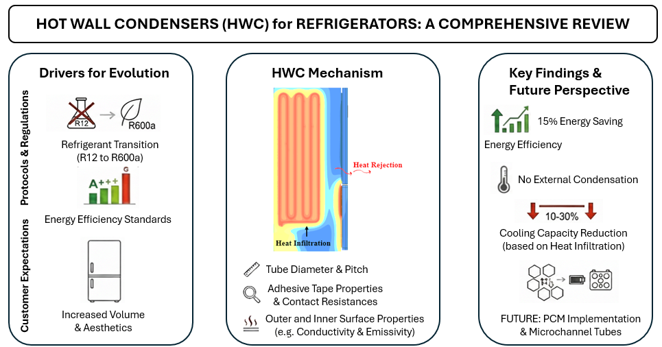
This study examines the evolution of condenser technologies in household refrigerators, focusing on the potential for improving energy efficiency with hot-wall condensers (HWCs). Factors influencing this development, including refrigerant changes, consumer expectations, global regulations, and environmental factors, are evaluated. Design features, advantages, disadvantages, limitations, and comparisons with other condenser types are presented for HWCs. The review identifies key parameters affecting HWC performance: pipe diameter and pitch, outer surface material properties, adhesive tape properties, and contact resistances. The effects of environmental factors such as ambient temperatures and heat transfer coefficients are also considered. The results indicate that HWCs can increase energy efficiency and reduce energy consumption by up to 15%. Furthermore, the risk of water condensation on HWC refrigerator surfaces is low, even in high-humidity environments. However, designs should also consider heat leakage into the refrigerated compartments; research indicates this infiltration can lead to a 10%–30% reduction in cooling capacity. The article also provides information on potential parameters that have not been previously studied and will guide future research. Design and integration are critical for successful implementation. Future research should focus on improving HWC designs and developing optimization strategies for efficient and sustainable cooling solutions.Graphic Abstract
Keywords
The main function of refrigerators is to preserve food and beverages at ideal conditions for long periods of time. This process is achieved through the interaction of a series of complex components in the refrigeration system, one of which is the condenser. Condensers used in refrigerators are one of the main components of cooling systems, and therefore, the development of condenser technology is a critical factor affecting refrigerator performance and energy efficiency. Condenser technology has undergone significant changes over time in response to changes in refrigerator technology and the need for improvements. The factors driving these changes in refrigerator technology include refrigerant progressions, evolving customer expectations, changes in global standards, and environmental impacts. Among these, the impact of refrigerant progressions used in refrigeration systems is the most critical and influential. James M. Calm, in his study published in 2008, discussed how the use of refrigerants has changed over time, considering environmental impacts such as ozone depletion potential (ODP) and global warming potential (GWP), and categorized them into four generations [1]. Anthony A. and Krishpersad Manohar have attempted to show that, in addition to these important environmental parameters, some significant events over time have also influenced the progression of refrigerant types [2]. Subsequently, McLinden and Domanski et al. extensively investigated the performance impacts of refrigerant changes for medium-pressure, high-capacity vapor compression systems, aiming to define the characteristics of an ideal refrigerant [3]. This topic was also a central theme in other key studies on refrigerant properties [4,5].
The second important factor that forced the change in condenser technology is the increasing customer demand over time. Among the expectations from a refrigerator, in addition to providing a cooling environment, there are features such as having a large volume, being functional, having low energy consumption, and having effective cooling performance. In addition, in 1992, the first international standards were presented for the European Union countries, so refrigerators began to be classified according to their energy consumption values, and as a result, customer awareness and sensitivity on energy rating increased [6,7]. Thus, the third factor that forced the change in condenser technology is the global norms. These additional demands and global standards have caused to increase in the heat in the system that has to be rejected from the condenser. Therefore, the condenser technology must be improved to increase the efficiency of the condensers.
This review article provides a comprehensive perspective to evaluate the condenser types used in refrigerators and to understand the increasing importance of hot wall condensers (HWCs), which have recently become widely used. While HWCs are increasingly adopted for their aesthetic and efficiency benefits, a comprehensive review that synthesizes their historical evolution, critically analyzes key performance parameters, and outlines future research challenges is currently lacking in the open literature. This paper aims to fill this gap by providing a holistic overview of HWC technology, serving as a valuable resource for both academic researchers and industrial engineers. In this context, the aim of the article is to deeply investigate the hot wall condensers in modern refrigerators, to evaluate the studies in the literature, and to provide a basis for future research on this type of condenser. To achieve this, the following sections are structured to guide the reader through the topic systematically: Section 2 traces the evolution of condenser technology. Section 3 provides a deep dive into the literature on HWC performance parameters. Finally, Section 4 explores novel concepts, and the paper concludes by summarizing the key takeaways and proposing a clear roadmap for future research.
2 Evolution of Condenser and Impacts on System Performance
The condenser technology used in refrigerators has undergone significant evolution over time. This technological evolution has seen a shift from basic copper tube coils to more sophisticated designs and materials [8].
James M. Calm divided the evolution of refrigerants into four generations. For the first generation (1830–1930), the focus was on creating a system that would perform cooling, and the type of refrigerant used was not important. During this period, natural resources such as ammonia, sulfur dioxide, carbon dioxide, and water were used. However, these substances were corrosive or toxic, a fact well-documented in historical reviews of early refrigeration [1,2]. James M. Calm focused on the physical properties and environmental impacts when classifying refrigerants. In 2023, referencing this study, Adeyanju Anthony A. and Krishpersad Manohar noted that significant events over time also influenced the changes in these classifications.
According to Adeyanju and Krishpersad, the second generation of refrigerants, focused on “Safety & Durability,” was shaped by two key events. The first was SO2 poisoning from refrigerator leaks in the 1920s. The second was the discovery of Freon in 1928 and its subsequent commercialization in 1931, which paved the way for the commercialization of household refrigerators [2]. In the 1930s, R12 became common in these refrigerators. Later, concerns about CFCs and the ozone layer led to the use of R22 [4]. The Montreal Protocol in 1987 banned CFCs and HCFCs in Europe [9,10]. The Kyoto Protocol was held in 1990 to reduce greenhouse gas emissions promoted FC and HFC gases like R134a, as outlined in the Kyoto Protocol and related regulations [11,12]. The environmental impact of these gases was also a significant topic of discussion [13]. James M. Calm marked the 1990s HFC transition as the start of the 3rd generation, focusing on Ozone Depletion Potential [1]. After 1990, Global Warming Potential also became a concern. By 2010, the EU banned HFCs, leading to the 4th generation: natural refrigerants with low GWP and ODP, such as Ammonia, CO2, and hydrocarbons. R600a became mandatory for small refrigerators in Europe in the 2010s, with other countries, including the US 2019, following suit [10]. If rearranging the timeline developed by Adeyanju Anthony A. and Krishpersad Manohar, referencing James M Calm’s study, for refrigerants used in low-capacity household refrigerators, this new timeline given in Fig. 1 is obtained [1,2].

Figure 1: Refrigerant progressions in household refrigerators [1,2].
As seen from the timeline, NH3 was initially used as a refrigerant in household refrigerators, followed by a transition to R12 with the discovery of Freon gases, to R22 with the finding of Freon gas’s ODP, to R134a with the deepening of research and global agreements made, and finally to R600a after GWP effects were also taken into consideration [5]. As given in Fig. 1, for a condensing temperature of 40°C, when 1st generation NH3, 2nd generation R22, 3rd generation R134a, and 4th generation R600a are used compared to R12, 747%, 28%, 26% and 140% more heat removal per unit mass of refrigerant is required, respectively. This situation can be considered as an indication that when transitioning from the 1st generation to the 2nd generation, a smaller condenser was needed, and as a result, the commercialization of household refrigerators was facilitated with a simpler and more manufactural condenser. However, at the transition from R12 to the next group of refrigerants, more heat must be rejected from condensers. Therefore, this situation indicates that condenser performance needs to be improved.
Fig. 2 shows refrigerators produced in the 1930s and 1950s, the condensers used in them, and related advertisements [14–16]. The condenser of the refrigerator produced in the 1930s was used in a coiled form around the compressor in the upper section. In the relevant visuals from the 1950s, the condenser and compressor are not visible. This is because, to increase the refrigerator usable volume and to give refrigerators a more aesthetically pleasing appearance, the compressor was moved to the lower-rear section of the refrigerator, while the condenser, due to the transition to 2nd generation refrigerants, was mounted on the rear wall of the refrigerator as an externally coiled shape from side to side. This period, which began with the change to 2nd generation refrigerants, can be considered the first step in enforcing condenser technology change.

Figure 2: (a) The first refrigerator in 1930s; (b) The refrigerator used in the 1950s [14–16].
The commencement of R22 refrigerant usage after the 1970s and the increasing demand for larger volume refrigerators, as seen in Fig. 2, led to the necessity of improving condenser performance because of the limited area on the rear wall of the refrigerator. As is known, the performance of a condenser mainly depends on the heat transfer surface area and the heat transfer coefficient with the surroundings. To increase the heat transfer coefficient, the air velocity passing over the condenser needs to be increased, i.e., forced convection needs to be occurred [17,18]. Considering the refrigerators developed without fans in the early years, heat had to be removed from the condenser and even drawn from the evaporator inside the refrigerator by natural convection. In this case, the only solution to increase the effectiveness of the condenser was to increase the heat transfer surface area. As a solution to this situation, “Wire on Tube” type condensers, shown in Fig. 3, were developed. This condenser was created by welding wires onto serpentine type condenser tubes to increase the surface area [19]. With the development of this heat exchanger, condenser technology underwent a second transformation.

Figure 3: Wire on tube type condenser [19].
Another factor directing condenser technology is the necessity to reduce the energy consumption value of refrigerators in our world with limited energy production. As is known, one of the important factors in reducing the energy consumption of a refrigerator is to reduce the condensation temperature of the system. With the reduction of the condensation temperature, compressor work decreases, and cooling capacity and COP increase, thus energy consumption decreases [17]. The reduction of the condensation temperature indicates the necessity to develop more effective condensers when taking a limited application area for them on a refrigerator is consideration.
Refrigerators have higher energy consumption compared to other household appliances due to their continuously operating requirement. For this reason, developing countries have tried to raise consumer awareness by classifying energy-consuming electrical appliances to effectively use limited resources for energy production. The first standard indicating the energy class value in refrigerators produced for European Union countries was defined in 1992 [11]. According to this IEC62552 standard, the energy consumption values of refrigerators tested under certain fixed conditions are measured, and the Energy Efficiency Index (EEI) value is calculated according to the relevant standard by considering the internal volume value of the refrigerator and the temperatures of the compartments inside. The calculated value is compared with the Index value specified in the standard to perform energy classification [6,7].
Initially, energy classes ranged from A (most efficient) to G (least efficient). In 2010, A+++ was introduced, representing a 33% improvement over the base A class. A major update in 2023 redefined the A–G scale, requiring at least a 35% efficiency gain for a refrigerator previously rated A to qualify as A under the new system [7]. This push for greater efficiency has driven advancements in insulation, compressor, and heat exchanger technologies [20].
Rising customer expectations and market competition have led to increased internal volumes in refrigerators and the concealment of components like condensers and compressors. These aesthetic and functional demands have been a significant driver in the evolution of condenser technology. As illustrated in Fig. 2, consumer needs have shifted from basic cooling functions to expectations of high efficiency, customizable compartments with specific temperature and humidity controls, digital compatibility, environmental friendliness, and recyclability [21].
With these demands, condenser systems have evolved to become more compact, efficient, and quieter. The introduction of fan-assisted “fin-on-tube” evaporators in No-Frost refrigerators in the early 2000s marked a turning point by highlighting the advantages of forced convection. This principle was later adopted in condenser designs as well. Traditional “wire-on-tube” condensers, initially mounted on the rear wall and relying on natural convection, were redesigned for integration within the machine compartment to maximize heat exchange surface area. Over time, these systems were classified into two categories based on their convection mechanisms: natural and forced convection.
2.1 Condensers with Natural Convection
These types of condensers are systems where there is no fan in the condenser unit, and heat transfer with the ambient air occurs by natural convection. In Fig. 4, they can be listed as “Serpentine”, “Wire on Tube”, “Plate on Tube”, and “Hot Wall” type condensers.

Figure 4: Types of condensers with natural convection; (a) Serpentine tube; (b) Wire on tube; (c) Plate on tube; (d) Hot wall [14].
2.1.1 Serpentine Type Condensers
In the early days of refrigerators up to the 1950s, this type of condensers was used. As shown in Figs. 2b and 4a, the serpentine type condenser, which have a simple design, have a structure where the tubes are arranged horizontally along the rear wall of the refrigerator. This design, due to the limited heat transfer area, has some performance limitations.
The Wire on Tube (WoT) condensers are developed versions of the serpentine type of condenser design. These designs, as shown in Figs. 3 and 4b, increase efficiency by providing more heat transfer surface area with wires welded around the tubes. Although WoT type condensers were intensively used by manufacturing companies between 1950 and 2000, according to the performance/price index of a refrigerator, the WoT condensers are still preferred today to use in low-volume and low energy class (E, F) refrigerators. In the design of these condensers, the number, diameters, lengths of the tubes and wires, and the distance from the rear wall of the refrigerator are the main parameters.
2.1.3 Plate on Tube Condensers
Studies conducted to improve the performance of the condenser by increasing the heat transfer surface area should be done without reducing the effect of natural convection. Therefore, Plate on Tube (PoT) type condensers that consist of a perforated plate and tube, shown in Fig. 4c, took the place of WoT condensers. The louvered structures created on the plate offer a design with increased natural convection efficiency. The geometric shape of these louver details is the most important design parameter to provide effective natural convection. In addition to these parameters, the number, arrangement, material, diameter, length of the tubes and plates, and the distance from the rear wall of the refrigerator are other important parameters. PoT type condensers were intensively used by manufacturing companies by 1990, and they are still the preferred use for refrigerator with large volumes or low-energy class as they do not require a fan and are competitive in terms of Performance/Price index.
Using hot wall type condensers in the refrigerator cooling system as a cheaper solution method has recently become a preferred method. These types of condensers are designed to be in internal contact with the walls of the refrigerator, as shown in Fig. 5. When the refrigerator is operating, these condensers transfer the heat of the refrigerant to the outer walls, keeping the surface temperature above the dew point temperature of the ambient. The potential to be applied to almost all outer surfaces of the refrigerator provides a large heat transfer. Hot wall type condensers reject the heat of refrigerant outwards by natural convection, using the temperature difference between the ambient and condensing temperature.

Figure 5: Hot wall condenser and application to refrigerator [22,23].
The advantages of this design are as follows: it does not require a fan, thus it operates more quietly and consumes less energy, has no maintenance requirements, providing higher energy efficiency due to its high heat transfer surface, providing more refrigerator internal volume as it is placed inside the insulation. However, they also have some disadvantages; they may have lower heat transfer capacity compared to fan-assisted condensers when applied to low surface area, sensitive to ambient temperature differences, so the effects of environmental conditions can be more effective on.
The critical aspect of HWCs is that some of the heat rejected from the condenser passes into the internal volume of the refrigerator, and this heat needs to be compensated by the cooling capacity of the refrigeration system. Therefore, when designing HWCs, the heat from the condenser to be transferred to the internal volume of the refrigerator should be considered. Geometrically, the tube diameter, tube material, tube wall thickness, band material, band thickness, contact areas of the band material with the tube and surface, arrangement of the tubes, distance between the tubes, thickness of the insulation material, thermal conductivity of the insulation material, and the internal environment temperature of the refrigerator are the main parameters affecting the performance of HWCs.
It is worth noting that other sections of the high-pressure refrigerant tube are also used for localized heating purposes, such as the ‘Frame Heater’ for preventing condensation at the door gasket and the ‘Evaporation Tray Heater’ for defrost water removal. However, the scope of this review is focused on the Hot-Wall Condenser as the primary heat rejection component of the system.
2.2 Condensers with Forced Convection
Customer demand, which initially started with the expectation of just a refrigerator that could cool food, has evolved over time into new demands such as large volume, effective cooling, low energy consumption, usability and functionality, and so on. These demands have led to the development of condensers with higher capacity, efficiency, quiet, and compact features in times. Especially with the development of forced convection evaporator technology in the early 21st century, it can be foreseen that the heat rejected from the condenser can be met by increasing the heat transfer coefficient with the environment instead of increasing the surface area, thus obtaining a more compact structure. This compact heat exchanger was taken into the machine compartment of the refrigerator, expanding the volume of the refrigerator towards the rear, and aesthetically more pleasing refrigerators, defined as “Clean Back,” could be produced. The condensers with forced convection, which initially started to be produced by bringing “wire on tube” condensers into folded and rolled forms, have been produced in different types over time with increasing studies and technological advancements. These condenser types are given in Fig. 6 in order of development progression.

Figure 6: Types of condensers with forced convection: (a) Wire on tube coil; (b) Plate on tube coil; (c) Fin on tube coil; (d) Micro/Mini channel [14].
2.2.1 Wire on Tube Coil Condensers
These types of condensers are more efficient and compact designs that emerged towards the end of the 20th century. In its simplest form, this design is obtained by bringing WoT condensers into folded or rolled form, as seen in Fig. 6a. With this design it allowed for the depth of refrigerators to be increased and, consequently, the internal volume of the refrigerator to be increased. These types of condensers must be used with a fan placed externally to the machine compartment or integrated with the condenser. Heat rejection is much higher compared to fanless WoT condensers. They can be produced in different forms in the limited volume of the refrigerator’s machine compartment, depending on whether an external or internal fan is used. In this condenser design, in addition to the main parameters of WoT condensers with natural convection, factors such as their shapes and main dimensions are also effective.
2.2.2 Plate on Tube Type Condensers
This condenser is obtained by bringing PoT condensers with natural convection into folded or rolled form, as seen in Fig. 6b. Its first examples are seen in refrigerators produced after the 2000s. Heat rejection is much higher compared to fanless PoT condensers. More heat transfer is obtained than with WoT-type condensers with a fan at the same external dimensions and the same airflow rates, but the air side pressure drop is quite higher than with WoT-type condensers. However, the condenser surfaces become clogged earlier compared to WoT due to dust accumulation, resulting in performance loss. Besides, they also have disadvantages like WoT condensers with fans, such as the need for maintenance and high noise due to the use of a fan. Therefore, due to having more disadvantages compared to WoT condensers, they are not very widely used in refrigerators.
2.2.3 Fin on Tube or Finned Tube Type Condensers
Finned tube condensers are condenser designs that use thin fins mounted on the tube surfaces, as seen in Fig. 6c. These fins significantly increase the heat transfer surface area, improving the performance of the condenser. These condensers are particularly notable for their high efficiency and compact structure. Unlike WoT and PoT type condensers, they are made of aluminum and/or copper materials. In this condenser type, factors such as the external dimensions of the condenser, tube diameter, tube thickness, number of fins, fin diameter, fin thickness, distance between the fins, and coil form are important.
2.2.4 Micro Channel Condensers
Microchannel condensers (MCHX) are an advanced version of the condensers with forced convection mechanisms. MCHX type condensers are compact designs that optimize heat transfer through thin channels in it, as shown in Fig. 6d. Generally, there are two different types: collector/distributor type and serpentine type. In the collector/distributor type, fluid enters and exits each microchannel plate at the same temperature with a low flow rate, naturally creating a uniform heat distribution in each channel. In the serpentine type, high flow rate fluid enters the microchannel plate from a single inlet, and the fluid temperature decreases in each serpentine channel, creating a non-uniform heat distribution. Therefore, for the same heat transfer surface area, the heat rejection of collector/distributor-type microchannel condensers is higher than the serpentine type. However, they are more expensive compared to the serpentine type in terms of cost.
The advantages of this condenser are providing high heat transfer efficiency, a more compact structure compared to other forced convection condensers, thus occupying less space, lightweight, and requires less material usage because it is made of aluminum. However, the main risk in using microchannel condensers is the blockage of the microchannels by particles or compressor oil, which can cause high pressure loss in the refrigerant circuit. This can result in an increase in compressor power and, therefore, energy consumption and refrigerator noise level. In the design of MCHX type condensers, factors such as channel size, width, and depth, fin thickness range, and type are important. The geometry and arrangement of the channels have a significant impact on heat transfer efficiency.
The critical regions in refrigerators in the aspect of heat gain are around the condenser and the machine room compartment, which have relatively high temperatures than the environment. Additional heat gain to the refrigerator from these regions means higher energy consumption for refrigerators. Therefore, the location and design of the condenser in the refrigerator also have a significant impact on system performance. Thus, when designing a condenser, the focal point should not only be to improve the energy efficiency of the system but also to reduce the occupying area and material amount [24,25].
Although condensers are classified as natural and forced convection types, they are evaluated in the industry under three types called Back (e.g., WoT or PoT with naturel convection), Compact (e.g., WoT, PoT, MCHX with forced convection), and Skin (Hot Wall) Condensers as shown in Fig. 7. Today, refrigerators with these three different types of condensers are still being produced. In general, back condensers are preferred in the production of inexpensive, low-functional, and low-energy-level refrigerators. Among compact condensers, micro/mini channel condensers are the most preferred by refrigerator manufacturing companies today because they provide high heat rejection at low air and refrigerant flow rates and have a high performance/price index. Although Skin Condensers perform heat rejection by natural convection, their performance is better than Back Condensers because all surfaces of the refrigerator cabinet can be used for heat transfer, their costs are lower than Compact Condensers due to not requiring a fan and easy labor, and they are quiet. Additionally, they do not create performance loss due to contamination that occurs over time in compact condensers.

Figure 7: Classification of condensers in industry.
On the other hand, the customer trend of using refrigerators built-in or side-by-side has emerged recently, as shown in Fig. 8. In these cases, the space between the refrigerator walls and furniture or other refrigerators can be very narrow. Using refrigerators with a HWC type in this way can lead to high performance losses and even insufficient cooling. When developing natural convection condenser-type refrigerators, ideal distances need to be determined by taking this effect into account. Some companies prefer to use an additional small compact condenser in the cooling system along with the hot wall condenser to overcome such situations and/or to achieve low energy consumption refrigerators, such as A and B energy classes.

Figure 8: Built-in and side by side installations of refrigerators at home: (a) Installation in niche; (b) Side by side installation.
If we rearrange the timeline developed by Adeyanju Anthony A. and Krishpersad Manohar, referencing James M Calm’s study, for condensers used in household refrigerators by including important milestones such as customer expectations, energy regulations, and steel pipe production, we will obtain a figure as shown in Fig. 9. As seen in Fig. 9, the two preferred condenser types in refrigerators after 2020 are mini/micro condensers and hot wall condensers. Considering the advantages of hot wall condensers over other condenser types, which were discussed in detail in the previous sections, it is seen that they will shape the future of refrigerator technology. Therefore, studies on hot wall condensers need to be increased, and their content should be investigated deeply.

Figure 9: Evolution of condensers used in refrigerators.
A comprehensive literature review was conducted on HWCs. Only 13 directly relevant articles could be identified in the literature. The evaluated parameters and their outputs in these studies are summarized in Table 1. As seen in Table 1, the focal point of most of the studies is to develop a mathematical model based on experimental analyses. In only two studies, the thermal effects of HWCs were investigated with two-dimensional numerical analysis.

As shown in Fig. 10, to determine the main parameters affecting the performance of HWCs, the points along the heat transfer path of the system should be followed. The main parameters affecting condenser performance can be temperatures and heat transfer coefficients of the external and internal environments, dimensions and thermal properties of the outer plate (e.g., thickness, thermal conductivity, and emissivity), dimensions and thermal properties of the adhesive tape (e.g., thickness, thermal conductivity, and width), dimensions and thermal properties of the heater tube (e.g., inner diameter, thickness, and thermal conductivity), the distance between heater tubes and the total tube length, the thermal resistance and contact area between the tube and the outer plate, the contact area and contact angle between the tape and the tube, the contact area and contact angle between the tape and the outer plate, the temperature, pressure, flow rate, and phase of the fluid inside the heater tube, thermal conductivity and thickness of the insulation material.

Figure 10: Heat transfer paths of hot wall condenser in refrigerator: (a) HWC schematic view; (b) Schematic representation of the heat transfer paths [22].
When evaluating the effects of these parameters, the targeted control volume is crucial. If the target control volume is only the condenser and the investigated quantity is condenser capacity, the situation yielding the highest condenser capacity can be considered the best result, such as increasing the tube length. However, if the control volume encompasses the entire refrigerator system structure and the condenser’s performance is evaluated in terms of its impact on the system’s cooling performance and/or energy consumption, adverse situations such as cooling capacity loss due to heat infiltration from the condenser to the refrigerator compartment and increased compressor work due to increase pressure drop inside the tube must also be considered.
Alihosseini et al. experimentally investigated wire-on-tube and HWCs on a household refrigerator. They compared the temperatures obtained from the evaporator and condenser and the energy consumption. The results shown in Fig. 11 indicate that while the evaporation temperatures remain the same, a lower condensation temperature is achieved with the HWC compared to the WoT condenser. Consequently, the COP of the refrigerator increased, and energy consumption improved by 15% in case a hot wall condenser was used in the refrigerator [34].

Figure 11: Parameters of Alihosseini et al.’s study: (a) Schematic of the product being tested; (b) The cooling cycle performed in this experiment: (c) WoT drawing; (d) HWC drawing [34].
Similarly, a study by Ghadiri and Rasti focused on reducing the energy consumption of a refrigerator with HWC placed on its rear and side walls. The study experimentally examined the existing state (Base) and the condition where the condensers on the side walls were deactivated (Side Condenser Removal) in terms of condenser and evaporator temperatures, compressor power, and energy consumption. As seen in Fig. 12, although the condensation temperature of the refrigerant significantly increased with the removal of the side wall condensers, the compressor work slightly decreased, resulting in a 1.2% reduction in energy consumption [25]. Ghadri and Rasti attributed this situation to the reduced pressure drop of the refrigerant inside the condenser due to the shorter tube length in the study. However, the increased cooling capacity due to reduced thermal infiltration could also be a primary reason for this situation.

Figure 12: Test results of Ghadiri and Rasti’s study: (a) Condenser outlet temperature for one on-off cycle; (b) Evaporator outlet temperature for on-off cycle; (c) Refrigerator power consumption for on-off cycle; (d) Annual energy consumption of the domestic refrigerator [25].
As observed, the results of these two similar studies show contradictions according to each other. This situation strongly points out the necessity of carefully determining the design, location, and parameters to investigate hot wall condenser applications in refrigerators.
3.1 Effect of External and Internal Ambient Temperatures and Heat Convection Coefficient on Condenser Performance
HWCs are generally applied to large vertical surface areas of refrigerators, such as the side and rear walls. Therefore, determining or realistically estimating the heat transfer characteristics of these vertical walls with the surrounding environment is a significant parameter in assessing condenser performance. The Nusselt number equation, dependent on the Prandtl and Grashof numbers, that was initially used for heat transfer calculations on a vertical plate is:
The first constant of 0.548 in the above equation is valid for only air and varies with the fluid type (e.g., 0.555 for oil, 0.33 for mercury). The heat transfer equation on a vertical plate at uniform temperature had been first solved by Pohlhausen. Subsequently, Ostrach numerically solved the heat transfer for Prandtl numbers between 0.001 and 1000. Kakaç developed a correlation for the average Nusselt number using Ostrach’s solutions [18]. The developed correlation by Kakaç is:
Le Fevre developed a Nusselt correlation that is applicable for a wide range of Prandtl numbers, and the results obtained closely matched Ostrach’s actual results. This equation is
It should be taken into consideration that the above correlations are valid for laminar flow conditions [18]. As a result of the studies, it was concluded that the Rayleigh number could be an indicator to determine the occurrence and effect of natural convection.
In this case, the Rayleigh number is expressed as Ra = Pr Gr. Airflow visualization in studies has shown that airflow remains laminar up to a certain critical Rayleigh number (109), and then turbulent flow begins above this critical value. In 1975, Churchill and Chu studied heat transfer occurring on heated vertical surfaces under laminar and turbulent flow conditions. The following equation was recommended by the authors for the dimensionless Nusselt number for a surface with uniform temperature [36].
This equation is generally valid for laminar flow conditions (105 < Ra < 109), while the following equation should be used for turbulent flow (Ra > 109).
Furthermore, the following equation provides more valid results for flat vertical plates with constant heat flux.
Although rarely, hot wall condensers are also implemented on the top wall of refrigerators in some cases. In this scenario, different correlations should be used for heat transfer on a horizontal wall. One of the most commonly used correlations is the following one proposed by McAdams [37].
while the characteristic length (Lc = L) is equal to the length of the wall for the equation related to heat transfer on a vertical wall, it is defined as Lc = As/P for a horizontal wall. In this case, the convection coefficient (hc) is calculated as:
when the studies in the literature are examined, it is seen that the correlation of Churchill and Chu was mostly preferred to use to evaluate the HWC [19,32,35]. Melo et al., used the correlation published by Churchill and Usagi in 1972 in their studies [22,23,31,38]. In CFD analyses, an overall heat transfer coefficient including radiation and convection was defined for prescribed walls of refrigerators. For example, Rebora and Tagliafico determined this value as 20 W/m2

Figure 13: Effect of outer heat transfer: (a) Effect of overall heat transfer on heat transfer coefficient [35]; (b) Effect of outer convective transfer coefficient [39]; (c) Change of radiative convective and overall outer heat transfer coefficient along the hot wall condenser [19].
Bansal and Chin, as shown in Fig. 13c, examined the effect of the average external heat transfer coefficient by considering the condenser tube length and the phase of the refrigerant inside the tube, pointing out that this effect is significant, around 80% for single-phase flow and 83%–95% for two-phase flow inside the condenser tube [19]. As is evident, a small change in the external convection coefficient has a significantly high impact on the condenser performance. Therefore, the external convection coefficient must be carefully determined.
The correlations used in the literature to determine external heat transfer have been developed under the assumption that the heated surfaces are completely open to a large environment. As shown in Fig. 8, if refrigerators are installed in built-in units or installed side by side, the ambient air adjacent to these surfaces will be in a confined volume, so the usability of the recommended correlations to determine the outer heat transfer coefficient in these cases should be re-evaluated. Furthermore, considering the physical effect of the external environment, determining the convection coefficient alone is not sufficient; the radiation effect must also be included. The radiation effect can be obtained using the following formula:
In this case, the heat transfer rate that is released from the hot wall condenser to the external environment can be expressed as:
Another factor affecting the performance of the hot wall condenser is the convection coefficient on the inside walls of the refrigerator. This convection coefficient varies depending on the type of cooling applied in refrigerators. A Static refrigerator cools by natural convection, while a no-frost refrigerator by forced convection. For refrigerators with a static cooling system, the convection coefficient for vertical and horizontal walls can be determined using the relevant Nusselt correlations given above. In the first studies in the literature evaluating hot wall condensers with mathematical models, the effect was neglected by assuming adiabatic walls with no heat transfer to the refrigerator compartments, since the refrigerator walls were covered by very thick and low conductivity insulation. In the studies by Espíndola et al. and Colombo et al., this effect was taken into account, and the above Nusselt correlations [Eqs. (7) and (8)] were evaluated as if a static type refrigerator model with natural convection on the walls for the physical conditions of the internal environment [31,38]. This approach was also adopted in subsequent key studies performed by Dall’ Alba et al., and Melo et al. on the topic [22,23,33].
Although these correlations are not suitable for refrigerators with forced convection, such as No-frost type refrigerators, they can be used to obtain a rough solution. In a no-frost type refrigerator, air flows into the compartments through an air duct with multiple outlets. Determining the convection coefficient on the inner walls of a No-frost type refrigerator is quite difficult because the air flow velocities and air motion inside the compartments vary depending on the positions of the air duct outlets corresponding to the walls. In a study conducted by Cui, He, and Mo, a refrigerator with different compartment’s temperature was analyzed by using a CFD program to determine the effect of the hot wall condenser on the additional heat gain to the refrigerator. It was concluded in the study that the heat gain of the refrigerator increased by 6.2% due to the heat infiltration from the hot wall condenser to the compartments [40].
As understood from Eq. (11), the heat released from the condenser to the external environment is a function of the heat transfer coefficient and the temperature difference between the external environment and the outer wall in contact with the condenser tube, for a constant surface area. At constant ambient temperature, increasing the condensing temperature causes to increase in the temperature difference between the refrigerator wall heated by the hot wall condenser and the ambient. Additionally, the increase in the temperature difference accelerates the free convection in the heated refrigerator wall. According to the above formula, the heat transferred from the condenser will increase with the increase of these two parameters. However, if the entire cooling system is considered, this situation will negatively affect the performance and energy consumption of the refrigerator. Because more heat released from the condenser will infiltrate to the refrigerator compartments, causing to increase in the refrigerator’s heat gain, and the additional heat gain will have to be compensated by the evaporator’s capacity. Furthermore, the compressor’s cooling capacity and efficiency will decrease with the increasing condensing pressure. Several key studies have highlighted that the refrigerator compartments act as a secondary heat sink for the condenser. This internal heat transfer path was a central element in the models developed by Colombo [31] and Espíndola et al. [22,23], and has been considered in other recent analyses as well [33,39]. In this case, the temperature of the refrigerator compartment is another significant parameter in determining the capacity of the condenser. A refrigerator consists of one or more compartments with different temperature zones. Target temperatures for the definition of these zones are specified in Table 2 as given in the IEC62552 standard [6].

For the same insulation thickness, the amount of heat transferred from the hot wall condenser to the −18°C freezer and +4°C refrigerator compartments, in other words, the heat infiltrations, will be different. For the environment with the largest temperature difference with the condenser, such as a freezer, the heat infiltration and the heat transfer rate of the condenser tube will be higher. The additional heat transferred from the condenser to the refrigerator compartment is undesirable for the cooling system efficiency of the refrigerator. This heat infiltration needs to be compensated by the system’s cooling capacity and removed from the system again. Bansal and Chin neglected the amount of heat transferred from the hot wall condenser to the refrigerator compartment in their mathematical model. As seen in Fig. 14a taken from their study, the condenser capacity deviates from experimental analyses by an average of 10%. The reason for this deviation was emphasized in the study as potentially due to the neglect of the heat transferred from the condenser to the refrigerator compartment [19].

Figure 14: Condenser capacity and heat Infiltration: (a) Condenser capacity comparison [19]; (b) Condenser capacity comparison [31]; (c) Heat infiltration ratio at 16 and 32°C ambient [22]; (d) Heat transfer rates to cabinet and ambient [31]; (e) Heat infiltration to chest freezer [33].
In the study conducted by Colombo et al., the heat transferred from the condenser to the refrigerator compartment was also considered, and the deviation between the model and the actual results was 2%, as seen in Fig. 14b. In this study, for different internal and external ambient temperatures, an average of 30% of the heat released from the condenser is transferred to the refrigerator compartment, as shown in Fig. 14d [31]. In the study conducted by Espíndola et al., the heat infiltration impact was obtained as 11.1% and 6.7% for external ambient temperatures of 32°C and 16°C, respectively, as seen in Fig. 14c [22]. In the study conducted by Dall’Alba on a chest freezer with a hot wall condenser, it was concluded that this effect varied between 10.5% and 12% for different external ambient temperatures and compressor operating ratios, and the impact was increasing linearly with increasing compressor operation rate, as shown in Fig. 14e [33].
3.2 Effect of Outer Plate (Thickness, Conduction Coefficient, and Emissivity)
HWCs are applied to the outer plate of the refrigerator from the insulation side, as seen in Fig. 10. The outer plate acts like a fin and increases the heat transfer area with the ambient. There is very low conductivity and very thick insulation material between the condenser and the cold internal environment. The heat rejected from the condenser moves to the ambient and refrigerator compartment. The ratio between thermal resistances through external and internal environments determines the proportion of heat transfer from the condenser to these two environments. The fact that the outer plate is made of a thin material with a high thermal conductivity compared to the insulation material ensures that its resistance is very low compared to the internal environment. Therefore, most of the heat released from the condenser passes to the external environment, as stated in the studies on HWC. Although the capacity of the condenser is the sum of the heat transfers to the ambient and internal environment, an effective one on it is the heat transferred through the outer plate to the ambient. Thus, the material type of the outer plate in terms of thickness, conductivity, and emissivity are important parameters for the hot wall condenser.
As a result of the study on HWC conducted by Rebora and Taglafico, as seen in Fig. 15a below, the thickness of the outer plate (P2) among the investigated parameters affects the overall efficiency of the system primarily, and this parameter was determined as the main factor [26]. In the study conducted by Hu et al., the change in the heat flux released from the outer plate according to the change in the distance between the HWC’s tubes for different plate thicknesses was examined under their mathematical. As seen in Fig. 15b, increasing the plate thickness, regardless of the distance between the tubes, significantly affects the heat flux released from the condenser [39]. In the study conducted by Espíndola et al., these three properties of the outer plate were examined, and their effects on the energy consumption of the refrigerator were evaluated as well. As seen in the graphs in Fig. 15c below, increasing the thickness of the outer plate and making it more conductive reduces the energy consumption of the refrigerator, while increasing the emissivity value increases the energy consumption of the refrigerator [22,23,38].

Figure 15: Effect of outer plate: (a) Effect of outer panel thickness [26]; (b) Effect of outer panel thickness and pipe distance [39]; (c) Effect of outer panel thickness, thermal conductivity and emissivity [22,23,38].
3.3 Effect of Adhesive Tape (Thickness, Thermal Conductivity, Width)
The tubes of the HWC are contacted to the inside of the outer plate with the tape material, as seen in Fig. 10. The tape has two functions in the refrigerator. One function of the tape is to keep the tubes in the designed position during the high pressurized expansion of the insulation material during the injection process. Another function that impacts heat transfer is to increase the contact area between tubes and outer plates. Therefore, the type of tape material in terms of thermal conductivity, the thickness in terms of thermal resistance, and its sizes in terms of contact area are important. Colombo et al., examined these three important parameters of the tape and was investigated in terms of their effects on the condenser capacity and heat infiltration, as seen in Fig. 16a. According to the results of their study, the thermal conductivity of the tape increases the capacity of the condenser rapidly up to a certain value (approximately 100 W/m

Figure 16: Effect of tape: (a) Effect of tape thermal conductivity, tape width and tape thickness [31]; (b) Contribution of tape to condenser heat transfer rate [22]; (c) Effect of tape material on energy consumption [23,38]; (d) Effect of tape material on heat transfer [22].
Espíndola et al., have examined the effects of the tube contact area between tube and outer plate, air cavities remaining among tube, tape, and outer plate, and the tape type on the heat path of the condenser to the outside environment in their mathematical model, as seen in Fig. 16b. In the study, aluminum tape was used in test no. 1, 2, 7, 8, 11, 12, 13, and polyethylene tape were used in the others. The effect of the air cavities among tube, tape, and outer plate on heat transfer is negligible. In the case of using polyethylene tape, a significant majority of the heat transfer, such as 95%, is made from the contact area between the tube and the plate, while in the case of using aluminum tape, a minimum of 60% of the heat transfer is made through the tape. As seen in Fig. 16d, when comparing the cases of aluminum and polyethylene tapes, the total heat transfer from the condenser covered with aluminum tape is higher than the case with polyethylene tape [22].
Only the effect of the sizes and thickness of the tape were investigated in the study of Colombo et al. in the literature. As seen in Fig. 16a, Colombo et al., resulted that increasing the width of the tape causes a small increase in the condenser capacity and a small decrease in heat infiltration. Even if small change in capacity and heat infiltration are observed, it can be pointed out that the tape thickness increases the condenser capacity and reduces thermal infiltration rapidly up to by approximately 60 mm, and after this value, the increase in capacity and the decrease in thermal infiltration show a small change [31]. In summary, when considering these three effects of the tape on the hot wall condenser, they can be ranked according to their importance as: the material type in the aspect of thermal properties, the thickness and sizes in terms of the contact area.
Rebora and Taglafico performed a 2D CFD analysis for a chest freezer with an HWC covered all around its outer walls. In the study, the total wall thickness (P1), outer plate thickness (P2), condenser pipe diameter (P4), and the effect of the contact resistance between the pipe/outer plate (P6) of the freezer were evaluated under sensitivity analysis in terms of condenser capacity. As seen in Fig. 15a, the effect of the pipe diameter (P4) affects the condenser capacity the least compared to the other parameters considered [26]. In another study, Peker and Özkan examined the effect of 2 different pipe diameters in a refrigerator with an HWC experimentally. As seen in Fig. 17a, they stated that increasing the pipe diameter increases the amount of heat transferred from the condenser by 8.9% and 5.2%, at a compressor speed of 1500 and 3000 rpms, respectively [35]. Although the condenser tube diameters used in the coolers and freezers are between 4 and 5 mm in general, Hu et al., examined a very wide range of pipe diameters in their mathematical model, such as 2–16 mm, although utopian. As seen in Fig. 17b, the thermal resistance of the condenser decreases with increasing tube diameter, approx. by 3% maximum. This situation shows that the amount of heat removed from the condenser can be theoretically increased a bit more if increasing the pipe diameter from 2 to 16 mm [39]. In the model considered by Hu et al., the heat transfer coefficient of the refrigerant in the tube was taken as a constant and the same for each tube diameter. In fact, if the diameter of the condenser tube is increased too much, the heat transfer coefficient in the tube decreases considerably due to the significant decrease in the flow rate of the refrigerant passing through it. In this case, the heat transferred from the refrigerant to the ambient will decrease, and the condensing pressure increases. To keep the condensing temperature the same, the amount of refrigerant and its flow rate need to be increased directly. This situation resulted in an increase in compressor power. If this compressor power increases significantly, the energy consumption of the system may increase considerably.

Figure 17: Effect of tube diameter: (a) Effect of tube diameter on condenser heat transfer rate [35]; (b) Effect of tube diameter on condenser overall thermal resistance [39]; (c) Effect of tube diamater on cooling capacity, compressor work, COP and energy consumption of refrigerator [32].
Cho et al. examined the effect of the condenser tube diameter in a feasible range, taking into account the change in amount of refrigerant regarding different tube diameters, in terms of the refrigerator’s cooling capacity, compressor work, and COP, by using their own mathematical model. As seen in Fig. 17c, by reducing the pipe diameter, the cooling capacity of the system decreases, the compressor work increases, and as a result, the COP of the refrigerator and freezer compartments of the system decreases. When the effect of the pipe diameter in terms of the refrigerator’s energy consumption is examined, so small impact was obtained. Similar to other studies, the effect of the pipe diameter on system performance and energy consumption is generally around 1%–2% [32].
Hu et al. investigated the effect of the distance between vertically placed tubes of a hot wall condenser in their mathematical model. As seen in Fig. 18a, the heat flux on the outer plate decreases linearly as the distance between the tubes are increased [39]. The linear decrease in the heat flux may be evidence that the thermal diffusion to tangential directions on the outer surface is not taken into consideration in their model, and may be only due to the decrease in the heat transfer contact area between the tube and the outer plate, based on the decrease in the total length of the condenser. Dall’Alba et al., examined the effects of tube pitch on the condenser capacity and the energy consumption of the freezer by taking thermal diffusion to tangential directions on the outer plate into account in their mathematical model. As seen in Fig. 18d, the capacity of the condenser decreases as the distance between the pipes increases, but the decrease in the capacity of the condenser is exponential. Therefore, after certain values, such as 70 mm of tube pitch, the decrease in capacity rapidly increased. Due to the decrease in the heat removed from the condenser, the condensing pressure of the refrigerant increased so that the compressor work and the energy consumption of the freezer increased rapidly [33]. Peker and Özkan experimentally examined 3 different condenser tube pitches in their study. As seen in Fig. 18c, unlike other studies, they obtained a significant increase in the condenser capacity by 12% and 7.2% for the compressor speed of 1500 and 3000 rpms, respectively, as the tube pitch was increased. The researchers concluded that this situation was resulted from the increase in the contact area of the condenser tube with the outer plate due to the increase in the length of the tube as the distance between the tubes increases [35]. In fact, when the tube arrangement configurations given in Fig. 18c are focused, the an increase in the tube length due to increase in tube pitch would be limited to max 6% increase, while in the study, it is stated that this area increase is 0.15–0.32–0.47 m2 for 20–40–60 mm of tube pitches, respectively. On the other hand, the condenser capacity increases due to the increase in tube pitches based on the extraordinary tube arrangement configurations obtained in the study which is meaningful. Although this situation seems to contradict studies that suggest closer pitches are better [33,39], the findings of Peker and Özkan [35] can be explained by the physics of heat spreading in a fin. When tubes are placed very close together, their thermal fields overlap significantly. This creates a small, intensely hot region on the outer plate, leading to a high local temperature but potentially inefficient heat rejection to the ambient air due to a low overall surface temperature gradient. As the tube pitch increases, the heat from the condenser is allowed to spread more effectively across a larger surface area of the outer plate (acting as a fin). This reduces the peak temperature but increases the average surface temperature, potentially enhancing both natural convection and radiative heat transfer from the entire panel. This suggests that there is an optimal tube pitch that balances the total tube length against the effectiveness of the outer plate as a heat-spreading fin. Finding this optimum is a critical design challenge and a key area for future research, as it is likely dependent on the plate’s thermal conductivity and the ambient heat transfer coefficient.


Figure 18: Effect of tube pitch or tube length: (a) Effect of tube pitch on condenser heat flux [39]; (b) Effect of tube material on condenser thermal resistance [39]; (c) Effect of tube pitch on condenser heat transfer rate [35]; (d) Effect of tube pitch on condenser capacity and energy consumption of chest freezer [33]; (e) Effect of tube length on cooling capacity, compressor work, COP and energy consumption of refrigerator [32].
Cho et al., have evaluated the effect of the condenser tube length on the cooling capacity, compressor work, and COP of the refrigerator. As seen in Fig. 18e, by reducing the tube length, the cooling capacity of the system decreases, the compressor work increases, and as a result, the COP of the refrigerator and freezer parts of the system decreases [32].
The effect of the material type of HWC was only evaluated in the study conducted by Hu et al. They investigated the parameter by using their own mathematical model, excluding the tape effect. As seen in Fig. 18b, the change in the thermal resistance of the condenser is quite low, either the pipe material is steel or copper. The researchers stated in the study that this change in thermal resistance regarding to material type is 2.04% for 100 mm of tube pitch, which is negligible [39].
3.5 Thermal Resistance and Contact Areas
As seen in Fig. 19, the heat from the condenser to the external environment is transferred to the outer plate by flowing through the contact area between the tube and the outer plate and over the tape, creating a bridge between the tube and the outer plate. Therefore, the contact area and thermal resistance between the tube and the plate, the contact area/angle between the tape and the tube, and the contact area between the tape and the plate are other important parameters affecting the condenser performance.

Figure 19: Effects of thermal resistance and contact area: (a) Effect of contact area between tube and plate [35]; (b) Effect of contact angle between tape and tube [27]; (c) Effect of tape width on condenser capacity [31]; (d) Effect of tape width on energy consumption [33].
3.5.1 Effect of Thermal Resistance and Contact Area between the Tube and the Outer Plate
Rebora and Taglafico analyzed the effect of thermal resistance between the tube and the outer plate on the performance of the condenser in their study by defining the thermal conductivity value to this region. As seen in Fig. 15a, according to the sensitivity analysis results, the thermal resistance between the tube and the outer plate (P6) is generally the second important parameter affecting the performance of the condenser after the effect of the thickness of the outer plate (P2) [26].
In the study conducted by Espíndola et al., as seen in Fig. 16d, the thermal resistance effect in the contact area was evaluated under the cases of using aluminum and polyethylene tape. When a tape with a high thermal conductivity, such as Aluminum, is used and the thermal resistance value between the tube and the outer plate is low, a certain part of the heat transfer from the condenser to the outer plate occurs from the contact area. Although the heat transfer rate passing through the contact area decreases by increasing the thermal resistance between the tube and the plate, the amount of heat transferred from the Aluminum (AL) tape to the plate increases, and because of this, there is a small change in the total heat transfer rate. When a tape with low thermal conductivity, such as Polyethylene (PE), is used, the entire heat transfer occurs from this contact area between tube and plate. When the thermal resistance of the contact surface is increased more, the amount of heat transferred from the condenser decreases to a point that almost no heat transfer occurs [22]. This situation shows that if a tape with a low conductivity value is used, good contact should be provided between the condenser tube and the outer plate along the length of the pipe, and great care should be given at this operation. In another study conducted by Espíndola et al., as seen in Fig. 16c, they investigated the effect of the contact area increase between the tube and the plate, defining as 1, 2 and 3 mm of the widths at different thermal conductivities of tape materials. As a result of their study, they obtained the result that for 1, 2, and 3 mm widths of contact area, in case of using PE tape, the energy consumption values of the system were approximately 48, 45.5 and 44.5 kWh/year, in case of using AL tape, the values were approximately 44.5, 44.2 and 44 kWh/year, respectively. As seen from the values, the case by using the PE tape with 3 mm width of contact area gives similar results to the case by using the AL tape width a 1 mm width of contact area. Regarding to these results, the researchers concluded that the required heat can be removed from the condenser by increasing the contact area between the tube and the plate, like giving a D-shaped to tube even if using a cheap tape such as PE [23]. Peker and Ozkan experimentally investigated the D-shaped form effect of the condenser tube. As seen in Fig. 19a, by switching from O to D form, they were able to increase the contact area between the tube and the outer plate by 32% and 67% for (O.D.) Ø4.0 and Ø4.76 mm of tubes, respectively. In the study, the tape material was AL. As a result of the study, in the case of D form, the heat transfer from the condenser caused a maximum increase of 3% compared to O form [35]. This result shows similarity with result of Espíndola et al. This situation shows that the tape material and contact area coupled parameters that should be optimized together.
The seemingly contradictory findings regarding adhesive tape materials (e.g., polyethylene vs. aluminum) warrant a deeper discussion. While aluminum tape offers inherently higher thermal conductivity, the overall system performance is a complex interplay of multiple factors. The superiority of one material over another may depend on variables not always controlled or reported in the studies. For instance:
• Thermal Contact Resistance: The actual thermal contact resistance between the tube, tape, and outer plate can be more influential than the tape’s bulk conductivity. A low-conductivity PE tape applied with a process that ensures minimal air gaps and excellent surface contact might outperform a high-conductivity AL tape with poor adhesion and significant contact resistance.
• Dominant Heat Transfer Path: As shown by Espíndola et al. [22], with PE tape, heat transfer is dominated by the direct tube-to-plate contact, whereas with AL tape, the tape itself becomes a significant heat transfer path. The overall effectiveness then depends on the relative quality and area of these two parallel paths, which can vary based on manufacturing tolerances.
• Cost vs. Performance Trade-off: The conclusion by Espíndola et al. [23] that a D-shaped tube with a cheaper PE tape can achieve similar performance to an O-shaped tube with an expensive AL tape is a crucial finding for industrial applications. It suggests that optimizing the contact geometry can be a more cost-effective strategy than solely relying on high-conductivity materials. This highlights the need for coupled optimization of both material properties and contact mechanics.
3.5.2 Effect of the Contact Area between the Tape and the Tube
Gupta and Gopal investigated the effect of the contact angle of the AL tape wrapped on the condenser tube through the condenser pipe length in their mathematical model, as shown in Fig. 19b. The condenser tube length decreases parabolically with the increase of the contact angle for the same condenser capacity [27]. The ideal is to ensure that the tape covers the entire pipe surface up to the contact are between the tube and the outer plate, thus increasing the heat transfer surface area between the tube and tape; however, this is very difficult to achieve in practice. The angle covered by the tape depends on the process applied to mount the condenser pipe on the outer metal sheet. In practice, this operation is performed manually by hand or using a rolling apparatus. This angle varies between 2.5–3.2 rad (140°–180°) with the manual operation, it can be increased to 3.2–4 rad (180°–220°) with rolling apparatus. If assumed that the angle is 3 rad at manual operation and 4 rad at the rolling apparatus, the tube length can be reduced significantly as 10% by using apparatus, regarding to the study. The contact angle of the tape and the tube also determines the volume of the air gap region formed between the tube, plate and tape. Gupta and Gopal, in their model, examined this gap by defining different heat transfer coefficients to region ranging from 0 to 2500 W/m2
3.5.3 Effect of the Contact Area between the Tape and the Outer Plate
When the studies in the literature are examined, the effect of the tape width is considered rather than specifically the contact area between the tape and the outer plate. Espíndola et al., have investigated the effect of the tape width for the huge range from 25 to 85 mm on the condenser capacity and the heat infiltration to the internal environment in their mathematical model. As seen in Fig. 19c, they obtained a slight increase in the condenser capacity and almost no change in heat infiltration by increasing the tape width [23]. Similarly, in the study conducted by Dall’Alba et al., they investigated this effect on the energy consumption of the chest freezer and obtained the maximum change as around 0.3% for the range from 20 to 60 mm of tape width, as seen in Fig. 19d [33]. When these studies are evaluated, it is seen that the effect of the tape width is negligible. But in practice, the minimum width required should be provided to protect the position of the tubes on the outer plate and to ensure good contact with the surface.
To understand the effect of refrigerant on condenser performance well, it is first necessary to understand the phase changes of the refrigerant that flows in the condenser tube inside from the inlet to the outlet, and the temperature and pressure changes depending on these phase changes of the refrigerant. Gupta and Gopal determined the temperature and pressure drop changes along the condenser tube of the refrigerant passing through the hot wall condenser in their mathematical model and compared them with experimental results. As illustrated in Fig. 20a, in region C, the refrigerant with the high temperature and in superheated vapor form rapidly lost its heat up to a certain tube length (approximately 4 m) from the condenser inlet and reached totally saturated vapor. Throughout region B (approximately 12 m), the refrigerant at saturated vapor form changed phase at a constant temperature and transformed to the saturated liquid phase. Throughout region A (approximately 2 m), the refrigerant continued to lose its heat, and a subcooling of 4 K was achieved. It is observed that the length required for the condensation region B is quite high due to the higher amount of heat that needs to be transferred during the phase change of the refrigerant. It is also clear that the pressure loss in the two-phase region is higher due to the additional loss caused by friction between the two phases [27]. Although subcooling in the condenser is theoretically unnecessary, it is required for some cases to ensure entirely complete the phase change of the refrigerant just before entering in capillary pipe if considering the refrigerator is working at different ambient temperatures. In the study performed by Bansal and Chin, the change in the capacity of the hot-wall condenser with respect to the refrigerant flow rate for different condensing and outdoor temperatures was experimentally investigated. As seen from Fig. 20b, the effect of temperatures for such specific conditions like 12°C and 15°C of temperature differences between the condensing temperature and ambient on the condenser capacity was found insignificant; however, the condenser capacity increased linearly with the increase in the refrigerant mass flow rate [19].

Figure 20: Effect of refrigerant: (a) Refrigerant condition in condenser tube [27]; (b) Effect of refrigerant mass flow rate and temperature difference between condensing and ambient [19].
3.7 Effect of Insulation Material
The amount of heat transferred from the HWC to the inner zones of the refrigerator is very low compared to the one released to the exterior environment due to the insulation material having the lowest conductivity and the thickest compared the others on the heat path given in Fig. 10. Although the effect of the insulation material on the condenser performance is almost negligible, it is an important parameter that affects the cooling capacity and energy consumption of the system due to heat infiltration, considering the efforts to develop thin-walled refrigerators with large volumes today. In a study conducted by Espíndola et al., the effect of different wall thicknesses of the freezer zone was investigated in the aspect of heat infiltration from the hot wall condenser tube to the refrigerator. While the same energy consumption value was obtained for the same wall thicknesses in both of the two different HWC tube configurations, it was concluded that the energy consumption increased very rapidly with the reducing of the freezer wall thickness and that this effect was due to the thermal infiltration passing from the hot wall condenser into the internal environment [23].
In addition to the primary design parameters discussed previously, the literature also explores several novel approaches and complementary technologies aimed at enhancing HWC performance or functionality. This section reviews some of these emerging areas, including the theoretical development of micro-channel HWCs, alternative manufacturing methods to increase contact area, and the integration of phase change materials (PCMs) to improve thermal management.
4.1 Micro Channel Hot Wall Condenser
Zhang et al., as shown in Fig. 21, considered a micro-channel hot wall type condenser that has an uncommon commercial application and theoretically evaluated its performance in their mathematical model. The model was developed to obtain optimum design parameters for different pipe numbers and pipe lengths of the new type of HWC. Their aim of the study was to reduce the mass of the HWC with this new design compared to the traditional condenser. For the same condenser capacity, it is observed that the required height for the vertical tubes decreases with the number of tubes and tube diameter. It was concluded that compared with the original condenser, the present optimal design parameters could reduce the total metal mass by 48.6% for the two wall two side design and by 26% for the two wall one side design. Thus, it was stated in the study that the present condenser was much better than the condensers usually used in actual domestic refrigerators [28].

Figure 21: Micro channel hot wall condenser [28].
4.2 A New Way to Increase the Contact Area between the Condenser Tubes and the Outer Plate
Raiayani, Sheht, and Mehta have numerically analyzed the contact area between the condenser tube and the outer plate by assuming that the outer plate was crushed in the form of a condenser tube as in Fig. 22. They concluded that the capacity of the condenser could be increased by increasing the contact angle between tube and outer plate [29]. Although it seems a suitable method to increase the performance of the condenser theoretically, in practice, its implementation in the production process can be expensive and difficult because it requires different molds to give the form of HWC tube lay-out to the outer plate.

Figure 22: Effect of contact angle between tube and outer plate: (a) Heat flux of the existing tube/plate configuration; (b) Heat flux of the 90 degree contact angle; (c) Heat flux of the 180 degree contact angle [29].
4.3 Hot Wall Condensers with PCM
Since HWC is applied to the outer plate, from the insulation side of the refrigerator, that makes it unique for the application of PCM as shown in Fig. 23a. In PCM applications to the condenser, generally paraffin wax in the form that has solid-solid phase change is preferred because of ease of application, low application cost, and no liquid and gas leakage. By using PCM on the condenser, it is aimed to extend the heat rejection process of the condenser until the compressor stops time, thus reducing the system’s operating rate and obtaining a lower condensing temperature by increasing the heat transfer of the condenser, thus reducing the system’s energy consumption [41]. In the literature, there are some studies about using PCM on the HWC to improve the performance of the cooling system. Cheng et al. applied a wax-formable PCM (SSPCM) on HWC tubes and investigated experimentally on a refrigerator. They observed that the COP of the system increased and the energy consumption decreased by 12% [42,43]. After that, Cheng and Yuan conducted a numerical study to investigate the effect of the ambient temperature, the internal temperature of the freezer, and the phase change temperature on the system performance. It was found that the COP of the system decreased and energy consumption increased when the ambient temperature increased or the temperature of the freezer decreased. It was also stated that when the phase change temperature was increased, the energy consumption showed a minimum value at 49°C, which is close to the phase change temperature of the SSPCM [44]. This result shows the importance of choosing a suitable PCM melting point [41].

Figure 23: Effect of PCM integration to hot wall condenser: (a) effect of SSPCM on hot wall condenser tube on condensing temperature and compressor work [44]; (b) Effect of SSPCM Integration to before and after condenser on COP of system [45].
Wang et al., a series of experiments were carried out by using different PCMs in different regions of a refrigeration cycle, as shown in Fig. 23b. They investigated the PCMs experimentally and numerically by placing them separately between the compressor and the condenser (PCMA), between the condenser and the expansion valve (PCMB), and between the evaporator and the compressor (PCMC). The aim of the PCMA, PCMB applications was to decrease the condensing temperature, to keep the sub-cooling temperature stabile at a certain temperature, respectively. Although different advantages have been obtained in each region where PCM has been applied, every PCM application has helped, in general, to increase the COP of the system. For instance, when the PCM has been placed between the compressor and the condenser (PCMA), it acted as an additional heat exchanger, and the COP has increased by 4% due to the lower temperature and pressure values obtained in the condenser. In general, the authors concluded that PCMB provided the highest COP, while PCMA provided higher system stability [45].
Joybari et al. highlighted a major shortcoming in the studies on the application of PCM to the refrigeration cycle, that the required amount of refrigerant had to be varied in each test, although the performance of the system was sensitive to the amount of refrigerant. Therefore, the researchers concluded that this situation clearly prevented making an adequate and proper comparison of the results [41].
In addition, the advantages and disadvantages of PCM in the studies examined in this review article, done by Joybari et al., are given in Tables 3 and 4 below, respectively.


In summary, the system COP can be increased significantly by using PCM on the HWC due to the lower condensing temperature achieved in condensers, a decrease in the operating ratio, and compressor work. However, the compressor start/stop frequency increases. This is a important situation to be careful about since it means that the compressor life is completed in a shorter time. Another situation to be considered is that refrigerators are designed to operate in environments between 10°C and 43°C ambient temperatures. It is necessary to ensure that the selected PCM does not have a negative impact on system performance under these conditions.
To provide a clearer overview of the performance impacts reported in the literature, a quantitative summary of the key findings from various studies is presented in Table 5. This table synthesizes the reported improvements in metrics such as energy consumption, COP, and heat transfer, as well as the magnitude of critical trade-offs like heat infiltration. As can be seen, design choices such as the condenser type or the application of PCM can lead to significant energy savings, typically in the range of 12%–15%.

In this study, firstly, the basic definition and functions of the condenser were discussed, and then how condenser technologies have evolved from the past to the present were examined in detail. In particular, the importance of HWCs, which have become popular recently, was focused on. Then, the design features, operating principles, and the advantages and disadvantages of HWCs compared to other types were explained in detail. In addition, important findings and performance evaluations of experimental and numerical studies on hot wall condensers obtained from the literature were reviewed within the scope of this study.
The common finding in general in the studies conducted in the literature the use of HWCs as one of the natural convection condensers reduces the energy consumption of the refrigerator. For instance, in the study conducted by Alihosseini et al., it was concluded that the energy consumption was reduced by 15% in a refrigerator with a hot wall condenser compared to one with WoT [34]. When all studies in the literature are evaluated together, the main design parameters affecting the performance of the condenser are as follows.
• The outer plate (thickness, conductivity, and emissivity)
• The adhesive tape (thickness, conductivity, width)
• The tube (diameter, distance between tubes, tube length, and tube arrangement)
• The contact areas: between Tube and Plate, Tape and Tube, and Tape and Plate
As a result of the studies, it has been revealed that optimizing the design parameters of HWC increases efficiency of the condenser, has the potential to reduce the refrigerant charge, and improves the overall performance of the refrigerator. In addition, one of the environmental parameters, the external heat transfer coefficient, has a significant effect on the performance of the condenser. According to the study performed by Bansal and Chin, the external heat transfer resistance accounted for 80% and 83%–95% of the total heat transfer for single and two-phase flows, respectively [19]. Therefore, special attention must be given when defining or determining the air-side heat transfer coefficient.
Another important impact affecting the condenser capacity and performance of the refrigerator is the position of the condenser tubes corresponding to the refrigerator compartments with different temperatures. For example, in the study conducted by Colombo et al., 32% of the heat transfer rate released from the condenser was transferred to the refrigerated compartments. Therefore, in the study, it was suggested as an important design criteria that the condenser tubes should not be positioned to the walls corresponding to the freezer compartment in order to reduce the unwanted heat infiltration from the condenser to the refrigerator [31]. In addition, Espíndola et al. stated that the heat infiltration was directly related to the condenser tube placement and insulation thickness of the refrigerator, and they calculated the heat infiltration in their model as 6% and 12% on average at 16°C and 32°C of ambient temperatures, respectively [22,23]. In this case, in addition to design parameters, the ambient and compartment temperatures and heat transfer coefficients, tube placement and arrangement, and the insulation thickness in which the condenser is placed are other important parameters to be considered when designing a hot wall condenser for a refrigerator.
When focusing on the missing points in the studies performed on HWCs, the potential topics for future investigation can be highlighted as follows:
• Effect of Tube Material: Our review identified that the effect of tube material (e.g., steel vs. copper) has been evaluated in only a single modeling study, which found it to be negligible [39], but this has not been experimentally verified. To validate these theoretical findings and assess the practical impacts on cost, manufacturability, and long-term performance, future experimental investigations on the effect of tube material are warranted.
• Condenser Tube Arrangement: As discussed in Section 3, the literature presents contradictory findings on the effect of condenser tube arrangement (e.g., tube pitch) on overall system performance [25,34,35]. This discrepancy highlights a critical knowledge gap. Therefore, future research should systematically investigate the external heat transfer coefficient on the outer wall under various tube arrangements and condensation temperatures to resolve these contradictions and establish clear design guidelines.
• Heat Infiltration Rate: This review has highlighted that heat infiltration from the HWC into the refrigerated compartments is a critical trade-off, with reported values varying significantly (e.g., from 6% to over 30%) depending on the study and conditions [22,31,33]. While the impact of ambient temperature and insulation thickness has been touched upon, a systematic and comprehensive analysis is still lacking. Future research should focus on developing a robust predictive model for the heat infiltration rate that accounts for a wider range of wall thicknesses, ambient conditions, and internal compartment temperatures, enabling a more precise optimization of HWC designs.
• Realistic Installation Scenarios: As noted in Section 3.1, standard natural convection correlations are developed for unconfined spaces. However, modern applications often involve built-in or side-by-side installations, creating a confined volume that may invalidate these assumptions. A significant gap exists in understanding this effect. Future work should focus on experimentally and numerically quantifying the impact of the gap distance between refrigerators on condenser capacity, system performance, and heat infiltration for such realistic installation scenarios.
• Validation of Novel Concepts: As presented in Section 4, novel concepts such as micro-channel hot-wall condensers [28] and alternative contact methods [29] have been proposed theoretically but have seen little to no commercial application or extensive experimental validation. To bridge the gap between theoretical potential and practical implementation, future work should focus on deepening these studies. This includes building and testing prototypes to verify the claimed benefits (e.g., mass reduction) and to assess their manufacturing feasibility and long-term reliability.
• Optimization of PCM Applications: The review of PCM applications in Section 4.3 revealed a significant advantage in reducing energy consumption but also a major drawback: an increase in compressor start/stop frequency, which could negatively impact compressor lifespan [42–44]. Furthermore, as highlighted by Mastani Joybari et al. [41], A consistent methodology for comparing results is lacking. Future research should therefore focus on overcoming these limitations, for instance by exploring hybrid PCM-control strategies to mitigate frequent cycling and by establishing standardized testing protocols to allow for a fair comparison of different PCM applications.
In this review, progress in condenser technology and important findings about the hot wall condenser, which can contribute to the next studies, have been presented. Further research in this area could contribute to the development of more efficient and sustainable cooling technologies.
Acknowledgement: The authors would like to thank BSH Ev Aletleri San ve Tic. AS. for their technical assistance.
Funding Statement: The authors received no specific funding for this study.
Author Contributions: The authors confirm contribution to the paper as follows: conceptualization: Gürcan Durmaz and Gökhan Gürlek; investigation: Gürcan Durmaz; writing—original draft preparation: Gürcan Durmaz; writing—review and editing: Gökhan Gürlek. All authors reviewed and approved the final version of the manuscript.
Availability of Data and Materials: The authors confirm that the data supporting the findings of this study are available within the article.
Ethics Approval: Not applicable.
Conflicts of Interest: The authors declare no conflicts of interest.
Nomenclature
| A | Area (m2) |
| COP | Coefficient of Performance |
| EEI | Energy Efficiency Index |
| Gr | Grashof Number |
| h | Heat transfer coefficient (W/m2·K) |
| k | Thermal conductivity (W/m·K) |
| L | Characteristic length (m) |
| Nu | Nusselt Number |
| P | Perimeter (m) |
| Pr | Prandtl Number |
| p | Pressure (Pa) |
| Q | Heat transfer rate (W) |
| Ra | Rayleigh Number |
| T | Temperature (K or °C) |
| U | Overall heat transfer coefficient (W/m2·K) |
| ε | Emissivity |
| ρ | Density (kg/m3) |
| σ | Stefan-Boltzmann constant (5.67 × 10⁻⁸ W/m2·K4) |
| Subscripts | |
| c | Convective |
| ex | External |
| in | Internal |
| L | Based on characteristic length |
| r | Radiative |
| s | Surface |
| ∞ | Ambient condition |
| Abbreviations | |
| CFD | Computational Fluid Dynamics |
| CFC | Chlorofluorocarbon |
| GWP | Global Warming Potential |
| HCFC | Hydrochlorofluorocarbon |
| HFC | Hydrofluorocarbon |
| HWC | Hot-Wall Condenser |
| IEC | International Electrotechnical Commission |
| MCHX | Microchannel Heat Exchanger |
| ODP | Ozone Depletion Potential |
| PCM | Phase Change Material |
| PoT | Plate-on-Tube |
| WoT | Wire-on-Tube |
References
1. Calm JM. The next generation of refrigerants-Historical review, considerations, and outlook. Int J Refrig. 2008;31(7):1123–33. doi:10.1016/j.ijrefrig.2008.01.013. [Google Scholar] [CrossRef]
2. Anthony AA, Manohar K. Performance assessment of low global warming potential alternative refrigerants. J Energy Res Rev. 2023;13(3):26–40. doi:10.9734/jenrr/2023/v13i3263. [Google Scholar] [CrossRef]
3. Domanski PA, Brignoli R, Brown JS, Kazakov AF, McLinden MO. Low-GWP refrigerants for medium and high-pressure applications. Int J Refrig. 2017;84(2):198–209. doi:10.1016/j.ijrefrig.2017.08.019. [Google Scholar] [PubMed] [CrossRef]
4. McLinden MO, Huber ML. (R)evolution of refrigerants. J Chem Eng Data. 2020;65(9):4176–93. doi:10.1021/acs.jced.0c00338. [Google Scholar] [PubMed] [CrossRef]
5. McLinden MO, Kazakov AF, Brown JS, Domanski PA. A thermodynamic analysis of refrigerants: possibilities and tradeoffs for Low-GWP refrigerants. Int J Refrig. 2014;38:80–92. doi:10.1016/j.ijrefrig.2013.09.032. [Google Scholar] [CrossRef]
6. IEC. IEC 62552-1:2015 household refrigerating appliances-characteristics and test methods-part 1: general requirements. International Electrotechnical Commission; 2015 [cited 2026 Jan 1]. Available from: https://webstore.iec.ch/en/publication/21805. [Google Scholar]
7. Official Journal of the European Union. Commission Delegated Regulation (EU) 2019/2016. 2019 [cited 2026 Jan 1]. Available from: https://www.legislation.gov.uk/eur/2019/2016. [Google Scholar]
8. Choi S, Han U, Cho H, Lee H. Review: recent advances in household refrigerator cycle technologies. Appl Therm Eng. 2018;132(9):560–74. doi:10.1016/j.applthermaleng.2017.12.133. [Google Scholar] [CrossRef]
9. Ozone Secretariat UN. Handbook for the montreal protocol on substances that deplete the ozone layer. 14th ed. New York, NY, USA: United Nations; 2020. [Google Scholar]
10. UNEP. Report of the twenty-eighth meeting of the parties to the montreal protocol on substances that deplete the ozone layer. In: Proceedings of the Twenty-Eighth Meeting of the Parties to the Montreal Protocol on Substances that Deplete the Ozone Layer; 2016 Oct 10–15; Kigali, Rwanda. doi:10.4324/9781003597681-5. [Google Scholar] [CrossRef]
11. EU. Regulation (EU) No 517/2014 of the European Parliament and of the Council of 16 April 2014 on Fluor-Inated Greenhouse Gases and Repealing Regulation (EC) No 842/2006. 2014. [cited 2025 Jan 1]. Available from: https://eur-lex.europa.eu/eli/reg/2014/517/oj/eng. [Google Scholar]
12. UN. Kyoto protocol to the united nations framework convention on climate change. 1997 [cited 2025 Jan 1]. Available from: https://digitallibrary.un.org/record/250111?v=pdf. [Google Scholar]
13. Newchurch MJ, Yang ES, Cunnold DM, Reinsel GC, Zawodny JM, Russell JM III. Evidence for slowdown in stratospheric ozone loss: first stage of ozone recovery. J Geophys Res. 2003;108(D16):2003JD003471. doi:10.1029/2003jd003471. [Google Scholar] [CrossRef]
14. Condensers for Refrigeration Appliances. 2016 [cited 2025 Jan 1]. Available from: https://www.secop.com/fileadmin/user_upload/technical-literature/danfoss-lectures/condensers_for_refrigeration_appliances.pdf. [Google Scholar]
15. Refrigerator-General Electric, Monitor Top, Cream, after 1931. Museums Victoria Collections. [cited 2025 May 20]. Available from: https://collections.museumsvictoria.com.au/content/media/43/196493-small.jpg. [Google Scholar]
16. Refrigerators of the past: a fascinating look at vintage refrigerator ads and photos from the, 1920s, to 1950s. Rare Historical Photos. [cited 2023 Apr 12]. Available from: https://rarehistoricalphotos.com/refrigerator-vintage-photos-and-advertisements/. [Google Scholar]
17. Çengel YA, Boles MA, Kanoglu M. Thermodynamics an engineering approach. New York, NY, USA: McGraw Hill; 2020. [Google Scholar]
18. Kakaç S, Yener Y. Convective heat transfer. Boca Raton, FL, USA: CRC Press; 1994. [Google Scholar]
19. Bansal PK, Chin TC. Design and modelling of hot-wall condensers in domestic refrigerators. Appl Therm Eng. 2002;22(14):1601–17. doi:10.1016/s1359-4311(02)00081-9. [Google Scholar] [CrossRef]
20. Arora RC. Refrigeration and air conditioning. Delhi, India: PHI Learning; 2014. [Google Scholar]
21. James SJ, James C, Evans JA. Modelling of food transportation systems—a review. Int J Refrig. 2006;29(6):947–57. doi:10.1016/j.ijrefrig.2006.03.017. [Google Scholar] [CrossRef]
22. Espíndola RS, Knabben FT, Melo C, Hermes CJL. Thermal performance of skin-type, hot-wall condensers, Part I: component-level modeling and experimental evaluation. Int J Refrig. 2020;110:231–8. doi:10.1016/j.ijrefrig.2019.11.010. [Google Scholar] [CrossRef]
23. Espíndola RS, Knabben FT, Melo C, Hermes CJL. Thermal performance of skin-type, hot-wall condensers, Part II: design guidelines for household applications. Int J Refrig. 2020;110:262–7. doi:10.1016/j.ijrefrig.2019.11.011. [Google Scholar] [CrossRef]
24. Belman-Flores JM, Barroso-Maldonado JM, Rodríguez-Muñoz AP, Camacho-Vázquez G. Enhancements in domestic refrigeration, approaching a sustainable refrigerator—a review. Renew Sustain Energy Rev. 2015;51:955–68. doi:10.1016/j.rser.2015.07.003. [Google Scholar] [CrossRef]
25. Ghadiri F, Rasti M. The effect of selecting proper refrigeration cycle components on optimizing energy consumption of the household refrigerators. Appl Therm Eng. 2014;67(1–2):335–40. doi:10.1016/j.applthermaleng.2014.03.024. [Google Scholar] [CrossRef]
26. Rebora A, Tagliafico LA. Thermal performance analysis for hot-wall condenser and evaporator configurations in refrigeration appliances. Int J Refrig. 1998;21(6):490–502. doi:10.1016/s0140-7007(97)00077-7. [Google Scholar] [CrossRef]
27. Gupta JK, Gopal MR. Modeling of hot-wall condensers for domestic refrigerators. Int J Refrig. 2008;31(6):979–88. doi:10.1016/j.ijrefrig.2008.01.003. [Google Scholar] [CrossRef]
28. Zhang H, Li J, Li H. Numerical simulations of a micro-channel wall-tube condenser for domestic refrigerators. Tinshhua Sci Technol. 2010;15(4):426–33. doi:10.1016/s1007-0214(10)70083-3. [Google Scholar] [CrossRef]
29. Raiyani AD, Sheth NR, Mehta NC. Thermal analysis of hot wall condenser for domestic refrigerator. Int J Sci Res. 2012;3(7):622. [Google Scholar]
30. Labigalini VB, Seixlack AL. Modelling of a hot-wall condenser used in domestic refrigerators. Int J Refrig. 2013;31(6):979–88. [Google Scholar]
31. Colombo EG. A numerical and experimental study on skin condensers applied to household refrigerators. West Lafayette, Indiana: Purdue University; 2016. [Google Scholar]
32. Cho W, Jang DS, Lee SH, Yun S, Kim Y. Refrigerant charge reduction in R600a domestic refrigerator-freezer by optimizing hot-wall condenser geometry. Int J Refrig. 2020;117(1):295–306. doi:10.1016/j.ijrefrig.2020.05.012. [Google Scholar] [CrossRef]
33. Dall’Alba CCS, Knabben FT, Espíndola RS, Hermes CJL. Heat transfer interactions between skin-type condensers and evaporators and their effect on the energy consumption of dual-skin chest-freezers. Appl Therm Eng. 2021;183:116200. doi:10.1016/j.applthermaleng.2020.116200. [Google Scholar] [CrossRef]
34. Alihosseini N, Mohammadi B, Yazdi ME, Salehi G. Experimental comparison of internal and external condensers effect on the energy consumption of household refrigerators. Energy Equip Syst. 2022;10(1):13–26. doi:10.1007/978-981-96-7941-6_1. [Google Scholar] [CrossRef]
35. Peker G, Burcu Özkan D. Performance evaluation of hot-wall condenser in a domestic refrigerator. Appl Therm Eng. 2023;233:121137. doi:10.1016/j.applthermaleng.2023.121137. [Google Scholar] [CrossRef]
36. Churchill SW, Chu HHS. Correlating equations for laminar and turbulent free convection from a horizontal cylinder. Int J Heat Mass Transf. 1975;18(9):1049–53. doi:10.1016/0017-9310(75)90222-7. [Google Scholar] [CrossRef]
37. Incropera FP, Dewitt DP, Bergman TL, Lavine AS. Fundamentals of heat and mass transfer. 6th ed. Hoboken, NJ, USA: John Wiley & Sons, Inc.; 2007. [Google Scholar]
38. Espíndola RS, Knabben FT, Melo C. Pros & Cons of using hot-wall condensers in household refrigerators. In: Proceedings of the 17th International Refrigeration and Air Conditioning Conference at Purdue; 2018 Jul 9–12; West Lafayette, Indiana. [Google Scholar]
39. Hu W, Jia P, Nie J, Gao Y, Zhang Q. A fast prediction model for heat transfer of hot-wall heat exchanger based on analytical solution. Appl Sci. 2019;9(1):72. doi:10.3390/app9010072. [Google Scholar] [CrossRef]
40. Cui P, He L, Mo X. Flow and heat transfer analysis of a domestic refrigerator with complex wall conditions. Appl Therm Eng. 2022;209:118306. doi:10.1016/j.applthermaleng.2022.118306. [Google Scholar] [CrossRef]
41. Mastani Joybari M, Haghighat F, Moffat J, Sra P. Heat and cold storage using phase change materials in domestic refrigeration systems: the state-of-the-art review. Energy Build. 2015;106:111–24. doi:10.1016/j.enbuild.2015.06.016. [Google Scholar] [CrossRef]
42. Cheng WL, Ding M, Yuan XD, Han BC. Analysis of energy saving performance for household refrigerator with thermal storage of condenser and evaporator. Energy Convers Manag. 2017;132(2):180–8. doi:10.1016/j.enconman.2016.11.029. [Google Scholar] [CrossRef]
43. Cheng WL, Mei BJ, Liu YN, Huang YH, Yuan XD. A novel household refrigerator with shape-stabilized PCM (Phase Change Material) heat storage condensers: an experimental investigation. Energy. 2011;36(10):5797–804. doi:10.1016/j.energy.2011.08.050. [Google Scholar] [CrossRef]
44. Cheng WL, Yuan XD. Numerical analysis of a novel household refrigerator with shape-stabilized PCM (phase change material) heat storage condensers. Energy. 2013;59:265–76. doi:10.1016/j.energy.2013.06.045. [Google Scholar] [CrossRef]
45. Wang F, Maidment G, Missenden J, Tozer R. The novel use of phase change materials in refrigeration plant. Part 1: experimental investigation and Part 3: PCM for control and energy savings. Appl Therm Eng. 2007;27(17–18):2893–901. doi:10.1016/j.applthermaleng.2005.06.011. [Google Scholar] [CrossRef]
Cite This Article
 Copyright © 2026 The Author(s). Published by Tech Science Press.
This work is licensed under a Creative Commons Attribution 4.0 International License , which permits unrestricted use, distribution, and reproduction in any medium, provided the original work is properly cited.
 Downloads
 Citation Tools
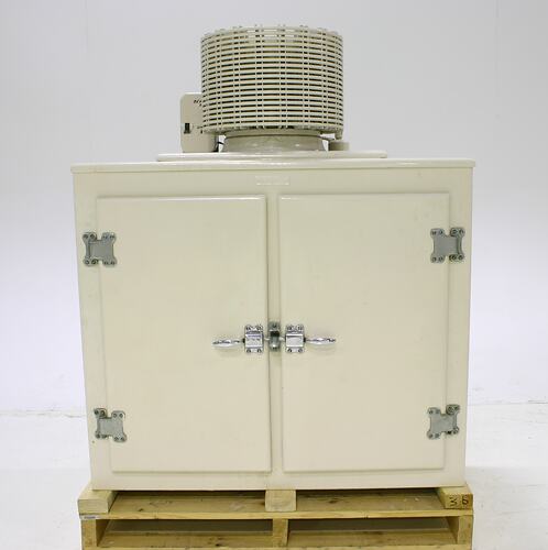