
 Submit a Paper
 Propose a Special lssue
 Open Access
ARTICLE
Harmonics Mitigation Using MMC Based UPFC and Particle Swarm Optimization
Ponjesly College of Engineering, Nagercoil, 629003, India
* Corresponding Author: C. Gnana Thilaka. Email:
Intelligent Automation & Soft Computing 2023, 35(3), 3429-3445. https://doi.org/10.32604/iasc.2023.024028
Received 01 October 2021; Accepted 12 April 2022; Issue published 17 August 2022
 View Full Text
 Download PDF
Abstract
The application of non-linear loads in the power electronic device causes serious harmonic issues in the power system since it has the intrinsic property of retrieving harmonic current and reactive power from Alternating Current (AC) supply that leads to voltage instability. To maintain a reliable power flow in the power system, an innovative Unified Power Flow Converter (UPFC) is utilized in this proposed approach. The conventional series converter is replaced with the Modular Multilevel Converter (MMC) that improves the power handling capability and achieves higher modular level with minimized distortions. The shunt compensator assists in minimizing the voltage fluctuations and maximizing the voltage stability under different load constraints. The Direct Quadrature (DQ) theory is utilized in this study to separate the harmonic components by generating reference frame current. The Proportional Integral (PI) controller aids in maintaining the direct current potential difference in the constant mode whereas the Pulse Width Modulation (PWM) generator helps in delivering optimized output to the MMC. The gain parameters of PI controller are optimized with the aid of employing Particle Swarm Optimization (PSO). The entire work is validated using MATLAB simulink and the obtained outcomes proves that this new UPFC is highly beneficial in minimizing the distortions with reduced Total Harmonic Distortion (THD) of 2.21%.Keywords
The eminence of power electronics is consistently elevated in many industrial applications. The usage of non-linear loads in the power electronics device causes the occurrence of harmonic current in AC transmission system and maximizes the overall reactive power. Hence, this proposed work concentrates on mitigating the source current harmonic distortions under different load conditions. Many researchers have made a research on the power flow control strategies using advanced algorithms with UPFC for regulating the energy flux in an efficient manner [1–3]. To increase the energy transfer capacity and stability, different methodologies are employed in the past days. In the existing works, the Power Quality (PQ) issues are overcome through the implementation of Shunt Active Power Filter (SAPF). This SAPF attains only source current compensation and fails to attain voltage compensation. Moreover, a high voltage stress is occurred in this filter. These issues are rectified by using Static Synchronous Compensator (STATCOM), which reduces the occurrence of voltage stress by making use of external Direct Current (DC) source. However, the STATCOM fails to accomplish the harmonic compensation and stability enhancement [4–8]. Before using STATCOM, the Static Volt-Ampere Reactive (VAR) compensator is preferred. It is usually used in the transmission applications that require voltage control at weak points in electrical power system. It supplies the reactive power with low voltage at heavy loads whereas it absorbs reactive power with high voltage at low load [9,10]. In this proposed work, an AC transference approach with UPFC that holds a wide range of application in the modern power systems is utilized due to its versatile functionalities. The UPFC incorporates the benefits of both STATCOM and Static Synchronous Series Compensator (SSSC) [11]. These two are coupled to the distribution line through the series and shunt transformers whereas these two are integrated with each other through a common DC link. Currently, the research on UPFC concentrates on system modeling and optimizes the dynamic execution of the grid. When any disruption is occurred in the transmission line, the fault current is automatically injected into the series part, which severely affects the safety of UPFC. Moreover, it takes much time to re-involve into the operation because of its serious inconsistency in upper and lower voltages, [12–16]. Hence, the series controller is replaced with the MMC to rectify all these limitations. Under normal operation, it works like an existing converter but if any flaws are detected, high impedance is automatically infused by the current limiting mode of MMC to conserve the normal operating condition. It is thus highly applicable for the high voltage and higher power industrial applications as it provides reliable output with minimum harmonics. By applying a cross coupling strategy based on d-q theory, the immediate retaliation and restraint in interference are provided between the original and reactive energy flux [17]. In this control strategy, the real and reactive power are independently manipulated by using quadrature axis voltage and direct axis voltage. The capacitor voltage and the bus voltage of UPFC are respectively manipulated by using direct axis framework and quadrature axis framework. The reference magnitude is analogized with the initial value and then provided to PI controller as the input. As it is highly essential to tune the parameters of PI controller for maintaining a constant DC link voltage, different approaches are employed in the process of tuning the PI parameters [18,19]. As it has plenty of advantageous impact in the process of monitoring the stability of control system, it plays a significant role [20]. The proposed PI controller provides good stability and minimizes the overshoot problem in a wider range [21,22]. The PI parameters are optimized by PSO approach and the optimized output is then given to the PWM generator. The PSO generates optimal solutions with the utilization of maximum iterations. The d-q theory is employed to obtain the desired amplitude and angle (phase difference) of compensator. Finally, the DC voltage is transformed to AC by using a three phase inverter.
Therefore, the UPFC is employed in this work, which involves in improving the power quality of the system and lessening the distortions with the assistance of the MMC. The operation of the converter is regulated by a PI controlled PWM generator. The corresponding gain parameter values of the PI controller are optimized by PSO approach, which in turn generates improved results.
The outline of the proposed work is structured as follows, a brief introduction is provided in section 1, Section 2 elaborately explicates the proposed methodology, Section 3 contains the obtained test results and Section 4 gives a short summation of this work. The proposed methodology is clearly explained in the following section.
The UPFC system is the combination of both SSSC and STATCOM that are interconnected by a DC-link voltage. In this proposed methodology, a novel UPFC based MMC is utilized as shown in Fig. 1. Because of having versatile functionalities, the UPFC is used in this system and it efficiently handles the relative energy in transmission lines. To maintain the stability of the grid and to minimize the transitory constituents of the generator during the occurrence of fault in the power grid, the UPFC immediately delivers true and relative power into the system. The series compensator and transmission line are serially connected by utilizing the series transformer. While converting the AC voltage into DC, the series converter delivers high ripple content, which is efficiently minimized by replacing the traditional series converter with MMC. It transforms the obtained DC voltage into 3 phase alternating voltage. The voltage is delivered to the non-linear load through the transformer. The stable load impedance independent current is obtained through the source input voltage and current by d-q theory. The actual and reference current are analogized by using Hysteresis Current Controller (HCC) to generate the PWM pulses. For preserving a stable voltage of DC-link and suppressing the harmonics, the PI controller is employed. In PI controller, the voltage of the capacitors is assessed and analogized with stable voltage. For the PI controller, the input is the obtained error and output is the highest value, in which the wave reaches the stable value of the current. The Transfer Functions (TF) of PI controller is computed as,
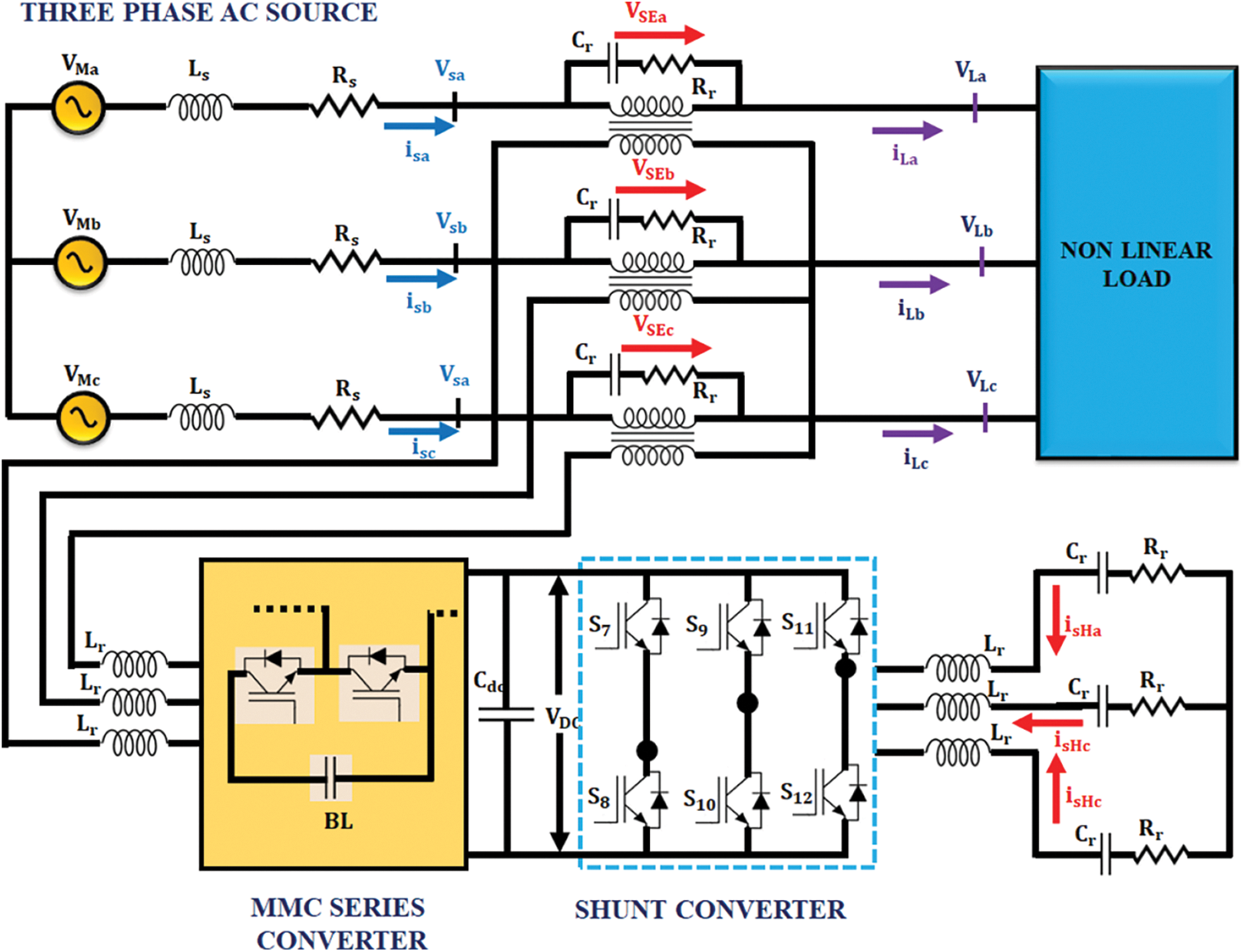
Figure 1: Proposed system circuit diagram
In Fig. 2, the topological structure of MMC is represented. This model comprises of three phases, in which the upper and bottom bridges are coupled with the AC line through the arm reactor.
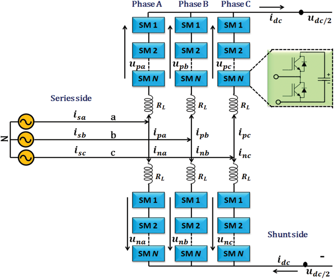
Figure 2: Design of series converter based on MMC
The characteristics of arm reactor is similar to the characteristics of inductor L and resistor
For individual block, the potential difference is specified as
Eliminate the arm resistors and consider the tip position with the top end of top bridge arm and bottom bridge arm at the equi-potential point.
At this point, the obtained voltage is
In the switching cycle,
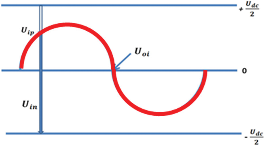
Figure 3: Relationship among the DC, bridge, and AC output voltage of MMC
The switching representation of upper-bunk and lower-bunk arm of MMC are obtained by making use of Kirchhoff’s voltage law. It is given as follows,
Consider
By computing Eqs. (1) and (2), it is represented as,
From the above equation,
The gross resulting voltage of top and bottom arm in sub component is given as,
At the time of modelling stage, eliminate the reactive voltage,
In each phase,
To perform substitution in Eq. (3), the mean switching cycle of MMC in three phase model is required.
The mean switching cycle of MMC is obtained by using the park transformation.
2.2 Three Phase Six Switch Inverter
Fig. 4 depicts structural representation of the three phase six switch inverter. It has two legs and each one of these legs has three power switches. In addition, three sources are placed at the DC link. In the three-phase AC loads, two phases are linked to the inverter legs and the remaining phase is connected to the DC source. The number of switches is effectively reduced in this system since the middle switches in the inverter legs get shared by two AC loads. This inverter invloves in two modes of operation like variable frequency and constant frequency modes, among which the former mode has adjustable amplitude of output voltages and frequency wheres the latter has variable amplitude and stable frequency.
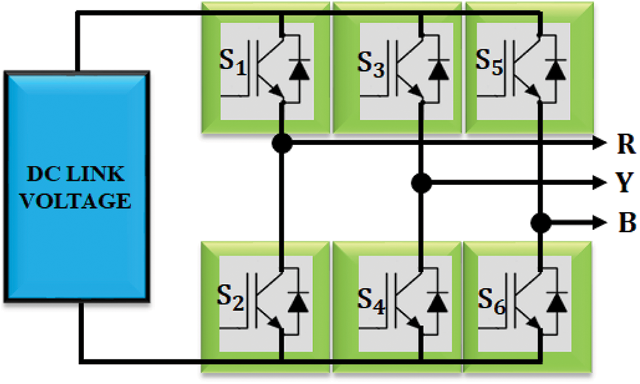
Figure 4: Three phase six switch inverter
2.3 UPFC System - DQ Theory Model
Three phase AC voltage is classified into zero, positive and negative sequence elements.
where
The input current of three phase is given as,
The estimated power is computed in eq. (11).
The general equation of d-q theory is written as,
where zero, positive and negative sequence power are represented as 0, 1 and 2 respectively. The overall power infused to the grid is evaluated as,
In Eq. (13), the parameter P and Q indicatethe real and reactive power of the transmission system.
The voltage and current of three phase input are transformed to
The parameters
From d-q theory, the reference signal for UPFC is computed as,
From the source potential and current, the reference signals are retrieved by using Park and Clarke transformation. The retrieved reference signal is analogized with the actual value by using hystersis comparator. The HCC generates the required PWM pulses, which are then injected to the series and shunt converters. The PI controller maintains the DC-link voltage as constant.
Tracking the real
where
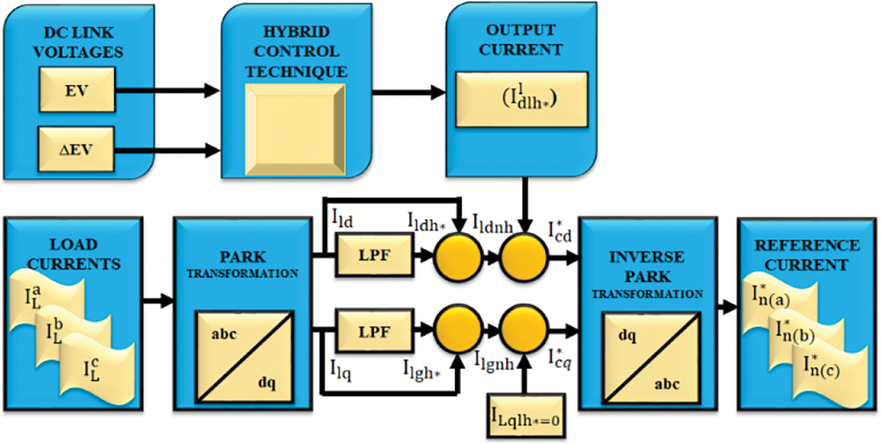
Figure 5: DQ theory modelling for UPFC system
To obtain optimal proportional and integral gain values, the PSO is utilized in this proposed approach, which is significantly portrayed in Fig. 6. The PSO is highly suitable for solving non-linear optimization problem. This optimization technique imitates the communal charateristics of various species of aves. The working principle of this algorithm is based on the amount of fragments in exploring the inner area of the multidimensional space. The main focus of this iterative algorithm is to enhance the parameters of PI controller, (
where
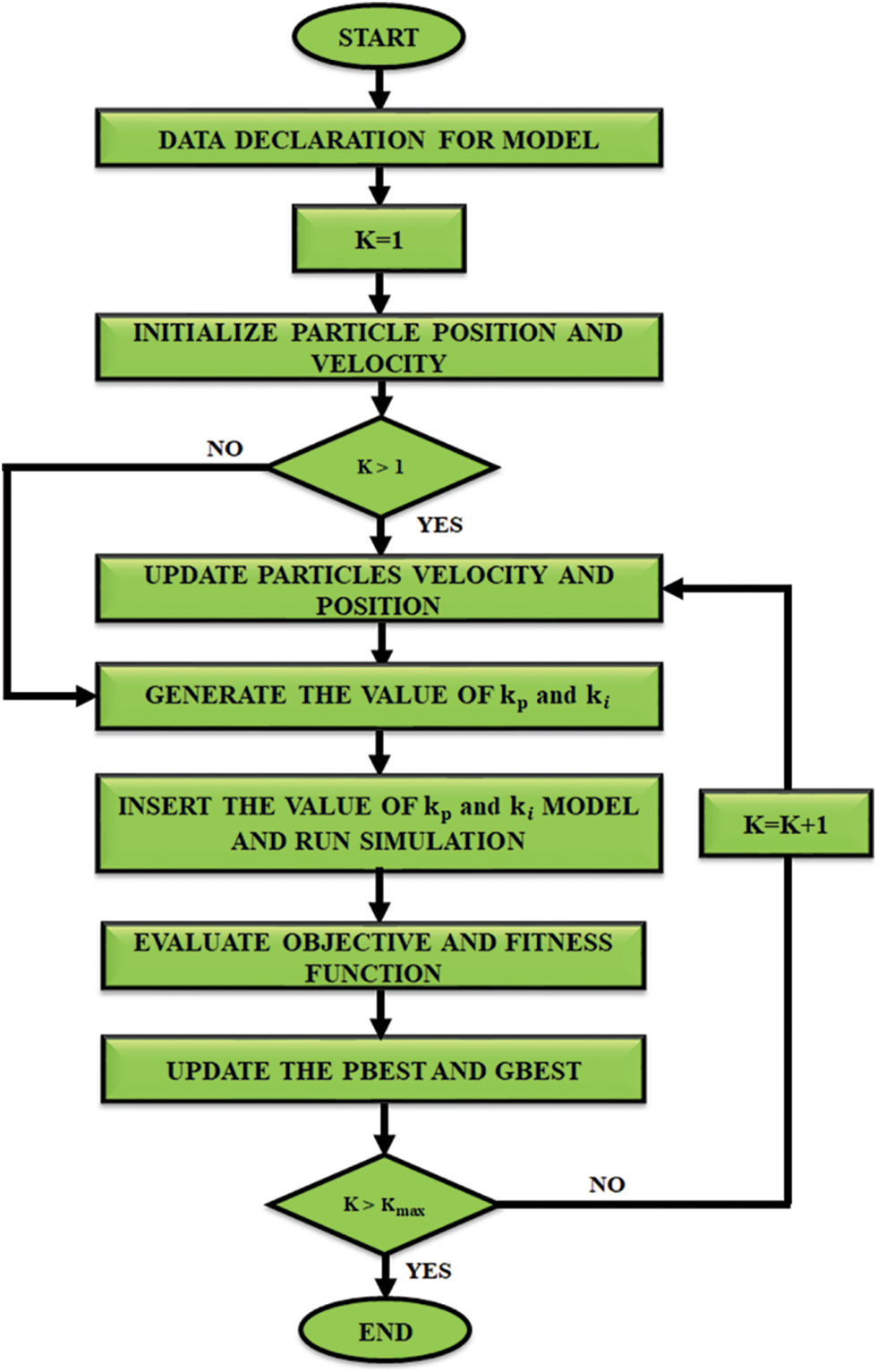
Figure 6: Fowchart for particle swarm optimization
Thus, an MMC utilizing a PI controlled PWM generator is proposed in this work. The obtained
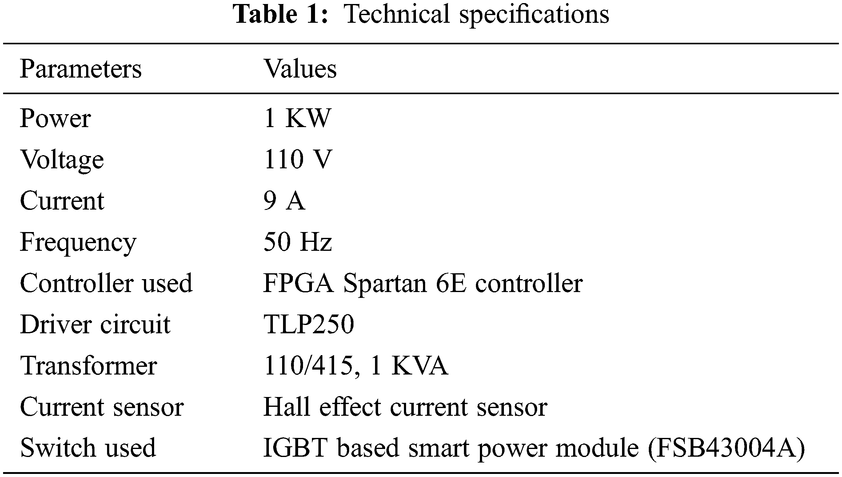
The proposed methodology is validated in MATLAB simulation. A supply of 100 V AC is provided in this system. The input power exhibits extensive distortion and this distortion is minimized by using the proposed system. In addition, it maintains the stabilty of power system in an efficient manner.The technical specifications of the proposed approach are specified in Tab. 1.
The waveforms indicating the input voltage and current are significantly portrayed in Fig. 7, which proves that the voltage value of 110 V is given as input. It is also proved from the waveform that the the proposed technique remarkably maintains the voltage stability, which in turm maximizes the overall performance of the system.
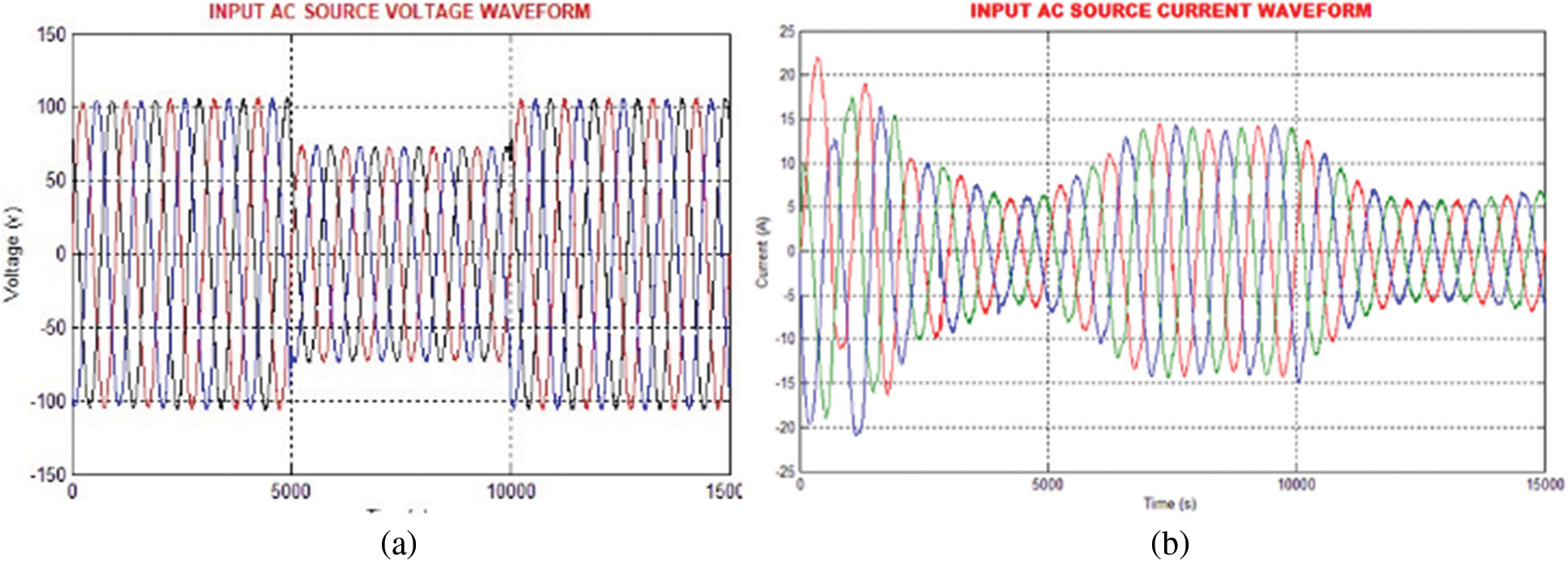
Figure 7: (a) Input AC voltage waveform (b) Waveform of input AC source current
The waveforms show maximum order harmonics but it is significantly minimized through the implementation of the proposed UPFC system. A AC voltage is delivered to the load and the UPFC regulates the voltage as constant, which is significantly illustrated in Fig. 8a.
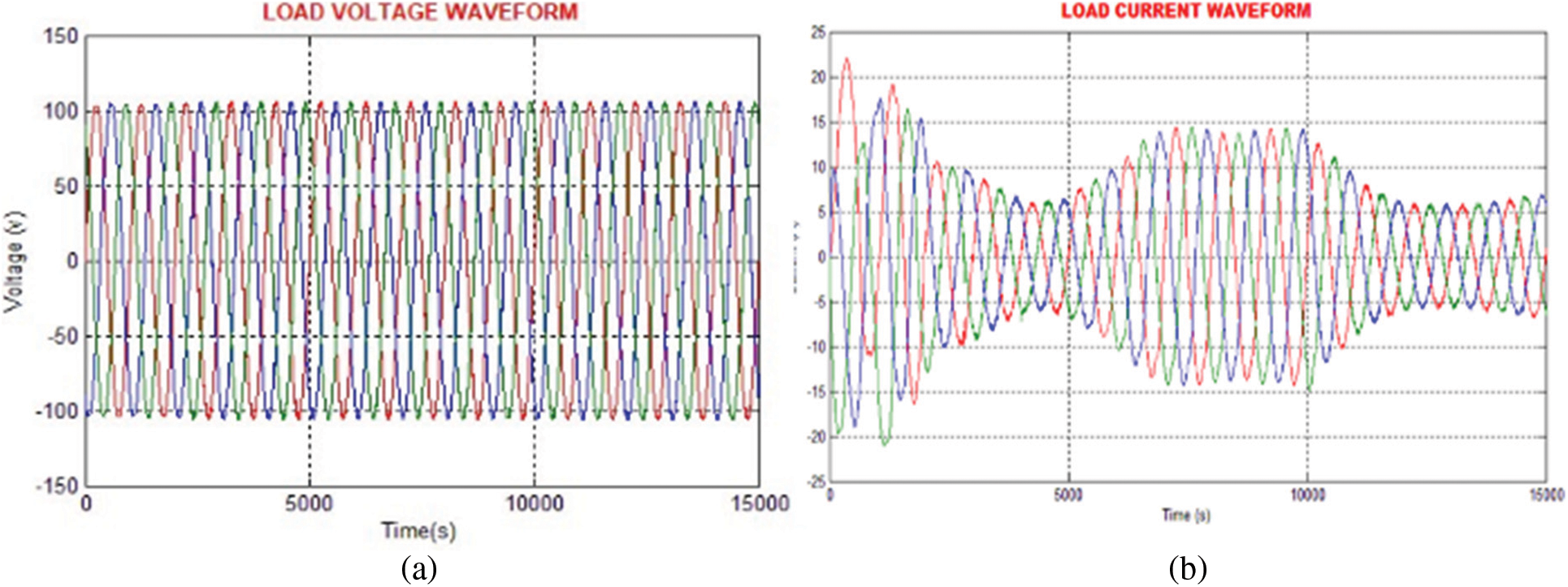
Figure 8: (a) Waveform of load voltage (b) Load current waveform
The sinusoidal load voltage and load current waveforms are illustrated in Fig. 8. The distortions are significantly reduced.
The DC link voltage waveform with PI controller is represented in Fig. 9a. The PI controller fails to constantly maintain the link voltage as it delivers high distortions as represented in the figure. In order to lessen the distortions, the PSO-PI approach is employed in this work, which maintains the DC link voltage as constant without any distortions as represented in Fig. 9b.
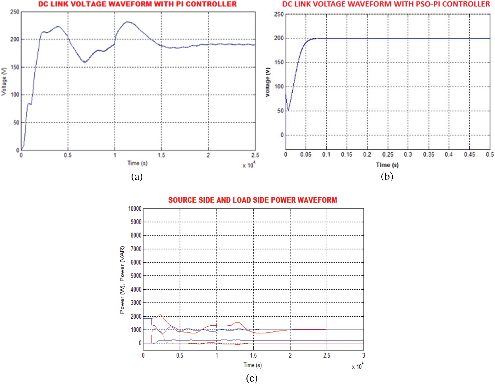
Figure 9: (a) Waveform of DC link voltage with PI (b) Waveform of DC link voltage with PSO-PI (c) Source side and load side power waveform
The UPFC system has a good capability to minimize the reactive power and to increase the real power at both sides as represented in Fig. 9c. The reactive power is increased with the assistance of the non-linear load at transmission line. At that time, the MMC converter absorbs the energy through PCC, which is stored in the DC link condenser. By utilising the shunt transformer, the shunt converter incorporates the real power in the PCC. Figs. 10a and 10b depicts the output voltage waveforms of MMC and the shunt converter.
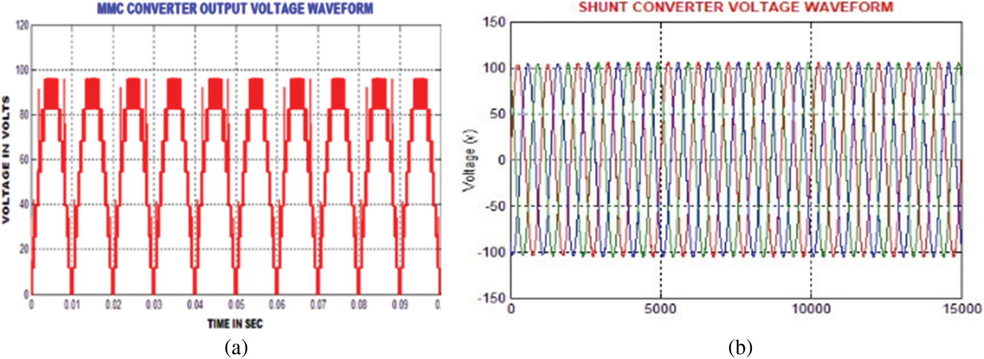
Figure 10: (a) MMC converter output voltage waveform (b) Wave form of shunt converter voltage
The waveforms representing the reference current and voltage are specified in Figs. 11a and 11b. This reference voltage and current waveforms are obtained from the source side by using DQ theory.
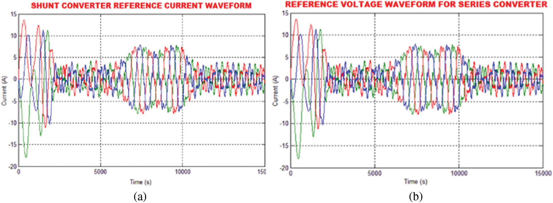
Figure 11: (a) Shunt converter reference current waveform (b) Reference voltage waveform for series converter
A prototype is modelled to scrutinize the validity and applicability of the proposed UPFC configuration. To test the efficiency of the proposed technique, the experimentation is carried out using various functioning circumstances through minimal and maximal extent adjustments with true power flux. The input current and voltage waveforms are evidently represented in Fig. 12.
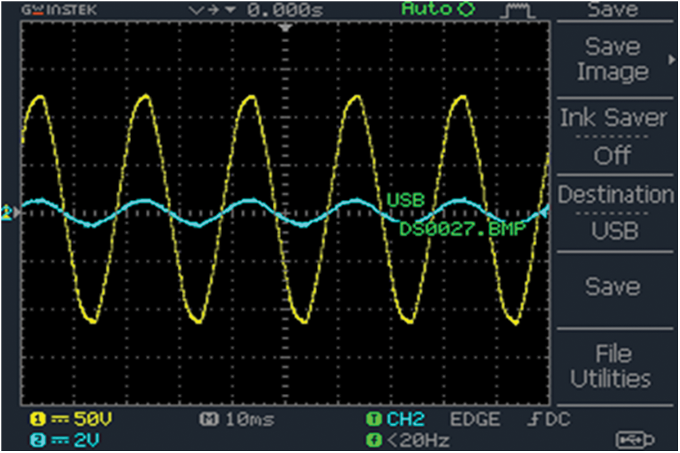
Figure 12: Experimental outcome of input current and voltage waveform with non-linear load
Figs. 13a and 13b respectively depict the sinusoidal load voltage and current waveforms. The link voltage is constantly maintained by using the PSO-PI controller in an efficient manner. The the waveform of DC-link voltage with PSO-PI controller is remarkably illustarated in Fig. 14.
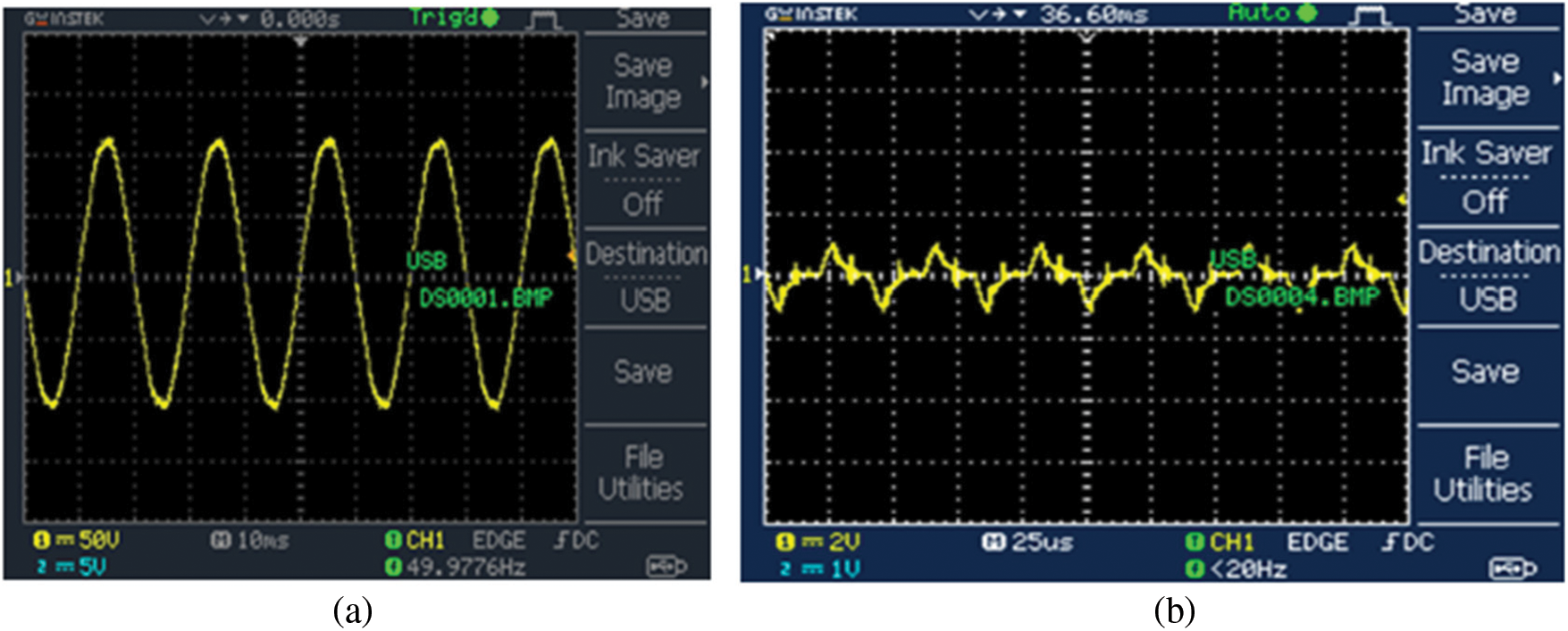
Figure 13: (a) Load voltage waveform with UPFC system (b) Load current waveform with UPFC system
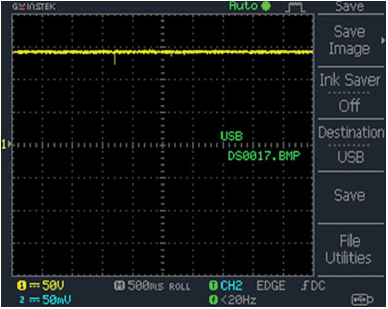
Figure 14: Waveform of DC-link voltage withPSO-PI controller
The occurrence of harmonic distortions, which are initiated by the applicaion of nonlinear loads makes the current as non sinusoidal. It is highly mandatory to eliminate the harmonics for enhancing the overall performance of the system without any interruptions. Hence, the PSO-PI is remarkably employed in this study to elimnate the harmonics. The THD compensation without optimization is shown in Fig. 15, which delivers the higher THD of 25.59%.
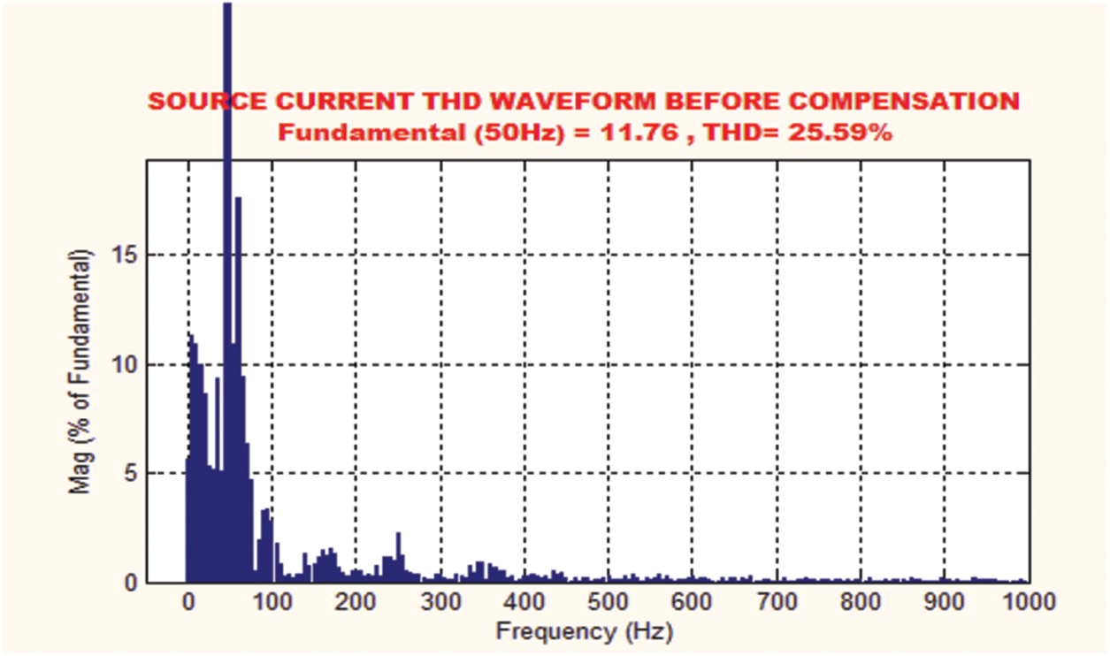
Figure 15: THD waveform before compensation
By using PI controller, the THD is dropped from 25.59% to 5.70%, which is significantly portrayed in Fig. 16a. The THD is further minimized to 2.21% by implementing the PSO-PI controller as represented in Fig. 16b. The optimum outcome is attained by employing PSO and the outcomes proves that the proposed approach is highly applicable for reducing the distortions in an optimal way.
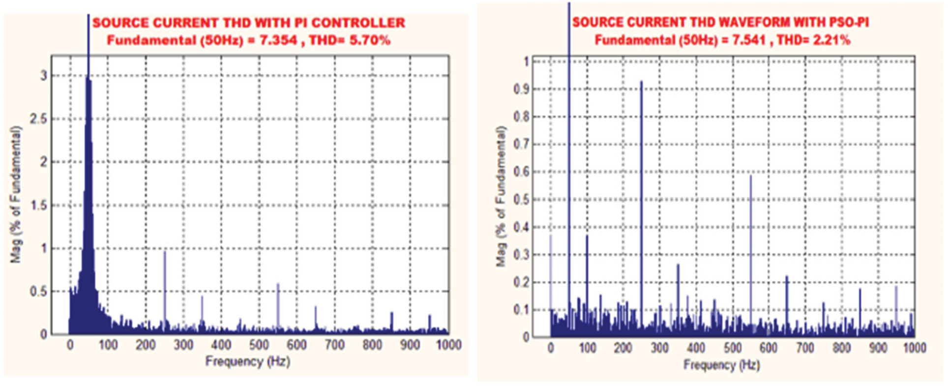
Figure 16: (a) THD with PI controller (b) THD waveform with PSO-PI
The comparison of the proposed PSO-PI in terms of THD is performed with PI and Fuzzy-PI controllers as mentioned in Fig. 17. The obtained THD values for PI and Fuzzy-PI controllers are 5.7% and 4.5% respectively. The proposed PSO-PI controller delivers the THD value of 2.21%, which is comparatively lesser than the other controlling approaches.
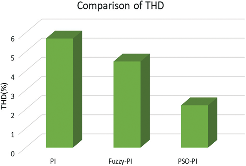
Figure 17: Comparison of THD
The primary aim of this present work is to mitigate the harmonic distortions in the transmission system. The proposed approach investigates the functioning criterions and real power behaviour of MMC-UPFC.The converter employs d-q theory for the generation of reference current, which in turn effectively reduces the harmonics in a wider range. The proposed PSO approach generates optimized results as it is equipped with maximum iterations. The entire work is simulated through MATLAB simulink and the obtaines outcomes are validated in an efficient manner. The obtained THD value with PSO-PI controller is given as 2.21%, which is comparatively better than the other approaches. Under various operating conditions, the DC bus voltage of MMC-UPFC is retained as constant within a secured range. Hence, the steady state performance of UPFC system is accomplished in an optimal way.
Funding Statement: The authors received no specific funding for this study.
Conflicts of Interest: The authors declare that they have no conflicts of interest to report regarding the present study.
References
1. R. Thirumalaivasan, Y. Xu and M. Janaki, “Power control with z-source converter based unified power flow controller,” IEEE Transactions on Power Electronics, vol. 32, no. 12, pp. 9413–9423, 2017. [Google Scholar]
2. L. B. G. Campanhol, S. A. O. D. Silva, A. A. D. Oliveira and V. D. Bacon, “Power flow and stability analyses of a multifunctional distributed generation system integrating a photovoltaic system with unified power quality conditioner,” IEEE Transactions on Power Electronics, vol. 34, no. 7, pp. 6241–6256, 2019. [Google Scholar]
3. J. Tang, H. Ma, X. Yang, X. Liu, X. Wang et al., “Research on ac transmission line fault ride-through control strategy of mmc-based unified power flow controller,” Journal of Engineering, vol. 17, no. 10, pp. 1580–1583, 2017. [Google Scholar]
4. L. Wang, C. S. Lam and M. C. Wong, “A hybrid-STATCOM with wide compensation range and low dc-link voltage,” IEEE Transactions on Industrial Electronics, vol. 63, no. 6, pp. 3333–3343, 2016. [Google Scholar]
5. Y. Neyshabouri, S. K. Chaudhary, R. Teodorescu, R. Sajadi and H. I. Eini, “Improving the reactive current compensation capability of cascaded H-bridge based STATCOM under unbalanced grid voltage,” IEEE Journal of Emerging and Selected Topics in Power Electronics, vol. 8, no. 6, pp. 1466–1476, 2020. [Google Scholar]
6. C. Li, R. Burgos, B. Wen, Y. Tang and D. Boroyevich, “Stability analysis of power systems with multiple STATCOMS in close proximity,” IEEE Transactions on Power Electronics, vol. 35, no. 3, pp. 2268–2283, 2020. [Google Scholar]
7. C. Li, R. Burgos, Bo Wen, Y. Tang and D. Boroyevich, “Analysis of STATCOM small-signal impedance in the synchronous d-q frame,” IEEE Journal of Emerging and Selected Topics in Power Electronics, vol. 8, no. 6, pp. 1894–1910, 2020. [Google Scholar]
8. T. Ahmed, A. Waqar, R. M. Elavarasan, J. Imtiaz, M. Premkumar et al., “Analysis of fractional order sliding mode control in a D-STATCOM integrated power distribution system,” IEEE Access, vol. 9, pp. 70337–70352, 2021. [Google Scholar]
9. L. Wang, C. S. Lam and M. C. Wong, “Minimizing inverter capacity design and comparative performance evaluation of svc-coupling hybrid active power filters,” IEEE Transactions on Power Electronics, vol. 34, no. 2, pp. 1227–1242, 2019. [Google Scholar]
10. S. Das, D. Chatterjee and S. K. Goswami, “Tuned-TSC based SVC for reactive power compensation and harmonic reduction in unbalanced distribution system,” IET Generation, Transmission & Distribution, vol. 12, no. 3, pp. 571–585, 2018. [Google Scholar]
11. S. Galvani, M. T. Hagh, M. B. B. Sharifian and B. M. Ivatloo, “Multiobjective predictability-based optimal placement and parameters setting of UPFC in wind power included power systems,” IEEE Transactions on Industrial Informatics, vol. 15, no. 2, pp. 818–888, 2019. [Google Scholar]
12. M. I. Mosaad, A. Alenany and A. A. Siada, “Enhancing the performance of wind energy conversion systems using unified power flow controller,” IET Generation, Transmission & Distribution, vol. 14, no. 10, pp. 1922–1929, 2020. [Google Scholar]
13. S. Wang, L. Jing, Y. Zhao, H. R. Wickramasinghe, X. Wu et al., “Operation of unified power flow controller as virtual synchronous generator,” IEEE Access, vol. 8, no. 9, pp. 162569–162580, 2020. [Google Scholar]
14. J. Liu, Z. Xu, J. Yang and Z. Zhang, “Modeling and analysis for global and local power flow operation rules of UPFC embedded system under typical operation conditions,” IEEE Access, vol. 8, no. 1, pp. 21728–21741, 2020. [Google Scholar]
15. K. Elamari and L. A. C. Lopes, “Implementation and experimental verification of a novel control strategy for a UPFC-based interphase power controller,” IEEE Transactions on Power Delivery, vol. 34, no. 6, pp. 2079–2088, 2019. [Google Scholar]
16. J. Sun, H. Zheng, C. L. DeMarco and Y. Chai, “Energy function-based model predictive control with UPFCS for relieving power system dynamic current violation,” IEEE Transactions on Smart Grid, vol. 7, no. 11, pp. 2933–2942, 2016. [Google Scholar]
17. B. Wen, R. Burgos, D. Boroyevich, P. Mattavelli and Z. Shen, “AC stability analysis and dq frame impedance specifications in power-electronics-based distributed power systems,” IEEE Journal of Emerging and Selected Topics in Power Electronics, vol. 5, no.12, pp. 1455–1465, 2017. [Google Scholar]
18. A. M. Ibrahim, S. A. Gawish, N. H. El-Amary and S. M. Sharaf, “STATCOM controller design and experimental investigation for wind generation system,” IEEE Access, vol. 7, pp. 150453–150461, 2019. [Google Scholar]
19. S. B. Pandu, C. K. Sundarbalan, N. S. Srinath, T. S. Krishnan, G. S. Priya et al., “Power quality enhancement in sensitive local distribution grid using interval type-II fuzzy logic controlled DSTATCOM,” IEEE Access, vol. 9, pp. 59888–59899, 2021. [Google Scholar]
20. F. M. Albatsh, S. Mekhilef, S. Ahmad and H. Mokhlis, “Fuzzy-logic-based UPFC and laboratory prototype validation for dynamic power flow control in transmission lines,” IEEE Transactions on Industrial Electronics, vol. 64, no. 12, pp. 9538–9548, 2017. [Google Scholar]
21. S. A. Q. Mohammed, M. S. Rafaq, H. H. Choi and J. W. Jung, “A robust adaptive pi voltage controller to eliminate impact of disturbances and distorted model parameters for 3-phase CVCF inverters,” IEEE Transactions on Industrial Informatics, vol. 16, no. 4, pp. 2168–2176, 2020. [Google Scholar]
22. K. Y. Ahmed, N. Z. B. Yahaya, V. S. Asirvadam, N. Saad, R. Kannan et al., “Development of power electronic distribution transformer based on adaptive PI controller,” IEEE Access, vol. 6, no. 8, pp. 44970–44980, 2018. [Google Scholar]
Cite This Article
 Copyright © 2023 The Author(s). Published by Tech Science Press.
This work is licensed under a Creative Commons Attribution 4.0 International License , which permits unrestricted use, distribution, and reproduction in any medium, provided the original work is properly cited.
 Downloads
 Citation Tools