
 Submit a Paper
 Propose a Special lssue
 Open Access
ARTICLE

Improved Control in Single Phase Inverter Grid-Tied PV System Using Modified PQ Theory
1 Faculty of Electrical Engineering &Technology, Universiti Malaysia Perlis, 02600, Arau, Malaysia
2 School of Electrical & Electronic Engineering, Universiti Sains Malaysia, 14300, Nibong Tebal, Malaysia
3 Department of Electrical, Electronic and Systems Engineering, Faculty of Engineering and Built Environment, Universiti Kebangsaan Malaysia, Selangor, 43600, Malaysia
4 School of Engineering, Jazan University, Jazan, Saudi Arabia
5 Faculty of Technology and Education, Helwan University, Cairo, Egypt
* Corresponding Author: Muhammad Ammirrul Atiqi Mohd Zainuri. Email:
Intelligent Automation & Soft Computing 2023, 37(2), 2441-2457. https://doi.org/10.32604/iasc.2023.037778
Received 16 November 2022; Accepted 24 February 2023; Issue published 21 June 2023
 View Full Text
 Download PDF
Abstract
Grid-connected reactive-load compensation and harmonic control are becoming a central topic as photovoltaic (PV) grid-connected systems diversified. This research aims to produce a high-performance inverter with a fast dynamic response for accurate reference tracking and a low total harmonic distortion (THD) even under nonlinear load applications by improving its control scheme. The proposed system is expected to operate in both stand-alone mode and grid-connected mode. In stand-alone mode, the proposed controller supplies power to critical loads, alternatively during grid-connected mode provide excess energy to the utility. A modified variable step incremental conductance (VS-InCond) algorithm is designed to extract maximum power from PV. Whereas the proposed inverter controller is achieved by using a modified PQ theory with double-band hysteresis current controller (PQ-DBHCC) to produce a reference current based on a decomposition of a single-phase load current. The nonlinear rectifier loads often create significant distortion in the output voltage of single-phase inverters, due to excessive current harmonics in the grid. Therefore, the proposed method generates a close-loop reference current for the switching scheme, hence, minimizing the inverter voltage distortion caused by the excessive grid current harmonics. The simulation findings suggest the proposed control technique can effectively yield more than 97% of power conversion efficiency while suppressing the grid current THD by less than 2% and maintaining the unity power factor at the grid side. The efficacy of the proposed controller is simulated using MATLAB/Simulink.Keywords
Environmental concerns, the limitation of traditional resources, and the rising demand for electrical energy, particularly of high quality and reliability, have resulted in the creation of distributed energy resources (DER) that typically used renewable energy (RE) sources [1]. However, RE sources often do not provide energy that is directly delivered to alternating current (AC) loads and/or the utility grid. Therefore, power electronic converters such as inverters are inevitable. The inverter topology for DER is usually single-phase or three-phase and its primary duty is to create an AC output voltage with low voltage distortion while adhering to safety and harmonics requirements (power quality) under both linear and nonlinear loads [2].
The main demerit of nonlinear load connected with DER system is the excessive current harmonics in the grid is one of the most serious power quality challenges [3]. The current harmonics might damage the conductors during high temperatures and overwhelm the electric power distribution system, especially in grid-connected inverters with renewable integration. To address this concern, the current harmonics can be minimized by using the appropriate control algorithms with the fundamental source current as its input [4]. A lot of research has been initiated on the topic of single-phase inverter controllers to provide effective management in terms of active and reactive power, current harmonics, and power factor at the grid side between the renewable energy sources, loads, and utility grids particularly linked to nonlinear loads. Reference [5] proposed the second-order generalized integrator based on hysteresis current control (SOGI-HCC) for a power-optimized architecture system. The SOGI-HCC controller is extract αβ components of the point of common coupling (PCC) voltage as well as load current and stabilizes the direct current (DC) bus voltage under sudden load conditions changes or high changes in solar insolation level. This controller also manages to control the injected current to the grid to improve the power quality. However, the main concern in this system was complex and had a slower response time due to each PV module being linked with a high gain DC-DC converter that functional with three modes of operation. Reference [6] proposed the controller based on proportional-integral (PI) control and Linear Active Disturbance Rejection Control (LADRC). This controller can compensate for the load current harmonics through the inverter output current and eliminates the complicated calculation of harmonic content analysis effectively. However, this controller had significant disadvantages which are difficulties in the mathematical model and the usage of a phase lock loop (PLL) for grid synchronization. Reference [7] proposed the current control scheme using the Lyapunov function which implemented the instantaneous reactive power approach often known as PQ theory to obtain the current reference of the parallel converter. This proposed method provides superior performance over conventional controllers such as rotating frame PI controllers or proportional-resonant (PR) control for the single-phase non-sinusoidal current tracking problem. The controller is also able to control the power flow through the grid interfaced with the load and PV power generation facility without the usage of PLL for grid synchronization. However, the main drawback of this controller is the Lyapunov function gain, λ needs to be chosen properly and doesn’t not able to integrate very well with sudden changes that mainly occur in PV renewable sources. The proposed control algorithm in this paper is adopted from PQ theory with some adjustments that can be realized in a single-phase system. HCC is chosen to replace the Lyapunov function because of its swift dynamic reaction and responsiveness to changes in the output load parameter. However, for two-level output voltage, a typical HCC has a high switching frequency at zero crossing of the output voltage [8]. To address the aforementioned disadvantages of typical HCC, a DBHCC is adopted in the modified PQ theory to provide the constant switching frequency to the inverter regardless of load variation or weak grid.
The DER system in this paper is using PV as its generation source. PV systems feature nonlinear I-V and P-V characteristics, with a single optimum working point known as the maximum power point (MPP), which varies alongside fluctuating environmental circumstances [9]. Under differing solar irradiances, an efficient and stable Maximum Power Point Tracking (MPPT) algorithm is desirable to maximize the power yield from PV system and provide a stable DC bus voltage. There are several studies have been done on the MPPT algorithm and the most common algorithm is based on disturbance characteristics which include the Hill climbing method [10], perturbation and observation (P&O) method [11] and incremental conductance (InCond) method [12]. These algorithms maximize power by introducing disruption into circuit variables. The benefit is that the algorithm structure is simple, nevertheless, it will oscillate around the MPP repetitively and their stability cannot be achieved at the same instant. The P&O method proposed in [11] creates a perturbation in the operating voltage of the PV array, whereas the hill climbing strategy proposed by [10] leads to a change in the duty ratio of the power converter and is more appealing given its simpler control structure. Despite this, steady-state oscillations arise in both techniques due to the perturbation. Consequently, the power loss might well be significantly increased. While the InCond method has indeed been developed by [13] to increase tracking accuracy and dynamic performance under rapidly fluctuating conditions. It is predicated on the assumption that the slope of the PV array power vs. voltage curve is zero at the MPP. In principle, the steady-state oscillations would be minimized due to the derivative of power concerning voltage disappearing at MPP. However, due to the resolution of digital implementation, a null value of the slope of the PV array power vs. voltage curve is relatively uncommon [14]. To capitalize all those advantages found in InCond method, this paper proposed a modified VS-InCond to be implemented as the MPPT algorithm. In this proposed method, the modified VS-InCond algorithm is formulated and model to provide a stable MPP under several irradiance condition and integrate with the PQ-DBHCC controller scheme. The comparison with the conventional InCond also being analyze thru modelling simulation.
This paper’s main contribution is to produce a high-performance inverter with a fast dynamic response for accurate reference tracking with high-efficiency power conversion and manage to suppress excessive current harmonics in the grid even under nonlinear load applications yet can be functional during both stand-alone and grid-connected modes. In addition, the proposed controller also was designed to regulate the grid current compensates, minimize the current harmonics generated by the local nonlinear loads and as well as adjusting the grid current phase to meet the local load reactive power demand in such a way that the final grid-connected current harmonic content and the grid-connected power factor can comply with the IEEE. Std. 929–2000 and IEEE Std. 1547–2003 requirements [15]. This proposed control algorithm comes with great advantages due to its good performance, simplicity, ease of implementation and less complex mathematical structure since PLL derivation is eliminated. The rest of this paper is structured as follows: The modeling and system descriptions are described in Section 2. The simulation results and the influence of several type’s nonlinear load are analyzed in Section 3. Finally, the conclusions are given in Section 4.
2 System Descriptions and Modelling of the Proposed Control Scheme
To integrate power conversion and MPPT function in one stage, a single-stage full-bridge inverter is used for converting DC to AC power and also for feeding the local loads and the utility grid, while tending MPP voltage regulation across the storage capacitor. Fig. 1 shows the proposed circuit modeling of the PV inverter grid-tied system. It mainly consists of a full-bridge DC-AC module, an LC filter, a nonlinear load, and a connection with the power grid. Typically, a conventional solar inverter employs two power processing stages, one via a DC–DC converter working in combination with the MPPT unit and the other via a DC–AC converter for power inversion. However, this proposed structure is simple since only one control stage is implemented, which generally leads to rather good voltage measurement at LC filter output. A leakage grid inductance is placed on the grid utility side to help minimize the loading effect. The system is tested with three types of nonlinear loads that are connected at the load side (at points a and b). The nonlinear load 1 is constructed by a bridge rectifier circuit with a capacitor and resistor connected in series. The nonlinear load 2 is constructed by a bridge rectifier circuit with a resistor. Lastly, the nonlinear load 3 is constructed by a bridge rectifier circuit with an inductor and resistor connected in series. Under these nonlinear load conditions, the DC-link capacitor produces energy sharing with the inverter in terms of inrush current while supplementing its energy from the inverter under constant DC-link voltage.
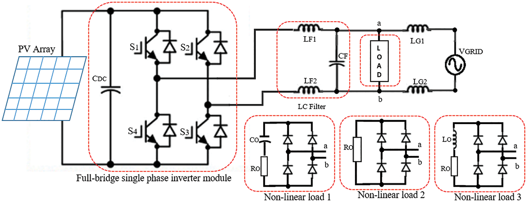
Figure 1: Proposed system modeling
2.1 Proposed HCC Scheme and Modes of Operation
The full-bridge single-phase inverter consists of four power switches. There are two operating modes for this topology. When switches S1 and S3 are closed (S2 and S4 are open), a positive voltage is applied across the output terminals. The second operating mode happens when switches S2 and S4 are closed (S1 and S3 are open) and the voltage is reversed, allowing reverse operation at the output circuit. To prevent shoot-through, switches on the same leg cannot be turned on simultaneously. The inverter switching scheme is using current control approach with the DBHCC method. In this control scheme, the measured load current of the inverter is compared with the generated reference current of the modified PQ theory. The current error is confined within a fixed hysteresis band (HB) which produces switching pulses for the inverters.
To achieve a lower switching frequency, the properties of the unipolar symmetrical pulse width modulation (PWM) technique and the typical HCC technique are merged in the DBHCC method. The proposed modified DBHCC switching control scheme is shown in Fig. 2 which has a unipolar inverter output voltage. Switches S1 and S3 operate at larger or rising HB, while switches S2 and S4 are operated at smaller or falling HB. The error signal band is determined by a double band which maintains the fundamental frequency and influences the average output polarity from positive to negative and vice-versa.
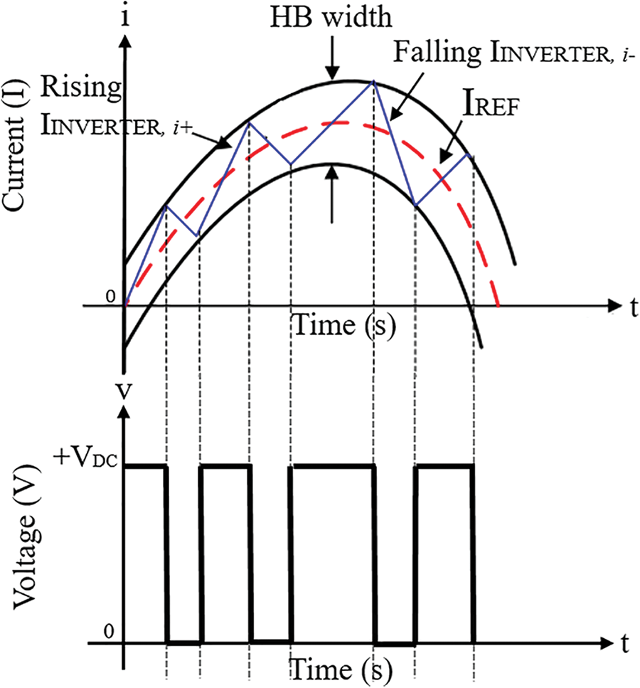
Figure 2: DBHCC switching control scheme
It can be stated that the switching frequency calculated using (1) is obtained as a function of DC source voltage, grid voltage, filter inductance, and HB width. The HB width should be determined very carefully to obtain a desired switching frequency and reference current tracking. The produced output voltage is bipolar and the inverter’s capacity to produce zero voltage level is not employed. Conventional HCC would normally have an error band within a fixed range causing constantly varying switching signals [16]. On contrary, the proposed DBHCC can achieve an almost constant switching signal when the reference current is produced within the upper and lower limits of the HB. The implementation of the controller, in reality, can be done with the help of advanced digital signal processing or field-programmable-gate-array (FPGA) [13].
2.2 Proposed Reference Current Design
The derivation of the sinusoidal command signal (IREF) implemented in the DBHCC switching scheme is based on the utilization of the PQ theory by applying the instantaneous load current and grid voltage. The maximum reference power value (PMPP), which is obtained from the VS-InCond algorithm, is used as the reference power PMPP, such that the DC-link voltage across CDC is constantly monitored based on the maximum power supplied by the PV array. Then the active power from the grid side is combined with PMPP as an active power component. Moreover, the reference reactive power QREF supplied to the load is a part of the power produced by the PQ theory block and conditioned by the single-stage inverter in such a way that both active and reactive current components are formed individually to accommodate active and reactive power requirements as shown in Fig. 3.
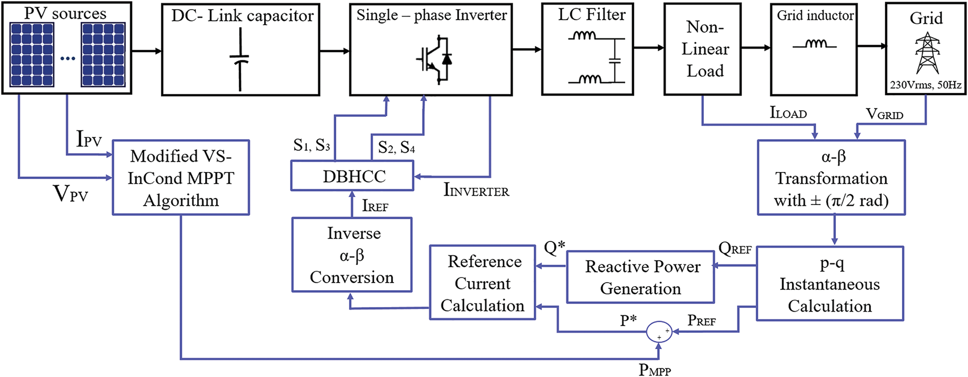
Figure 3: Detailed block diagram of the proposed controller
A single-phase system modification can be implemented to obtain four-sided symmetry. These were achieved by setting up a lag or lead of π/2 rad to both single-phase grid voltage and load current as represented by (2), (3) and establishing a virtual two-phase system from a single-phase system. As a result, all the characteristics and entitlements of a three-phase system are preserved in this single-phase system.
The transformation of current and voltage in terms of α-β configuration to the p-q configuration is made using (4) and (5) correspondingly, which generates P load as active power and Q load as reactive power.
Next, the acquisition of the reference current using (6) where P* is the summation of Pαβ and PMPP. This reference current, as shown in Eq. (6), governs the system’s active and reactive power.
2.3 Proposed Modified MPPT Algorithm Design
MPPT is a key control algorithm for determining the maximum input power in response to changes in the source of voltage and current [17]. Even though the MPPT algorithm strives to improve efficiency, it will not perform successfully unless both steady and variable circumstances are identified since the overall efficiency of a power conversion system is affected by all variations in source and load. Therefore, the MPPT algorithm used to optimize the efficiency of a PV system should take these changes in operating circumstances into account. As noted in the introduction, there are several basic and derivative MPPT approaches. The InCond method is chosen for the MPPT algorithm due to its quicker convergence under rapidly changing weather conditions. Aside from its accuracy and speed, the pace of convergence of MPPT operations is optimized by adjusting the step size of the perturbation based on its proximity to the MPP [18].
For the conventional InCond method, when the system’s operating point is to the right of the MPP, it may be quickly turned to the left of the MPP owing to an excessively high step size, causing the output power to oscillate near the MPP [12]. To minimize this disadvantage, a modified VS-InCond method is introduced. This method improves the steady-state performance of the control system and takes into account the maximum power tracking speed and steady-state accuracy of the system based on analysis of the dP/dV slope involved in the step calculation and also two limitations as proposed -0< step size <0 at the voltage source and 1> step size >0 at the current source. The proposed method’s fundamental concept is to initiate the algorithm to find a certain measured step. This step is automatically modified based on the position of the operating point. If the operating point is too far away from the MPP, the algorithm automatically increases the step size utilized in the duty cycle, allowing for quick tracking. However, if the operating point is near the MPP, the algorithm will automatically reduce the step size, as shown in Fig. 4. The step size, Mref is calculated based on the following (7) and (8) respectively.
where
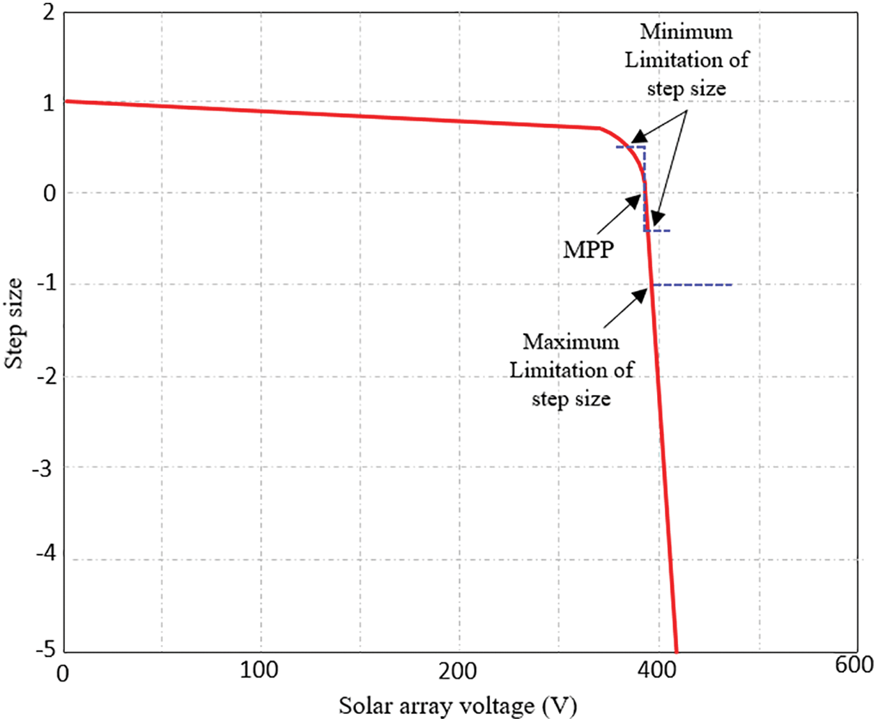
Figure 4: Variation of step size in the proposed algorithm
Fig. 5 shows the flowchart of the proposed modified VS-InCond algorithm. Firstly, the arbitrary reference value is set. After that after the sampling period, the PV current and voltage are detected and fed to the algorithm. The controller calculates the step size, and the voltage derivative is compared with the limitation condition. Finally, the PMPP is modified by the controller.
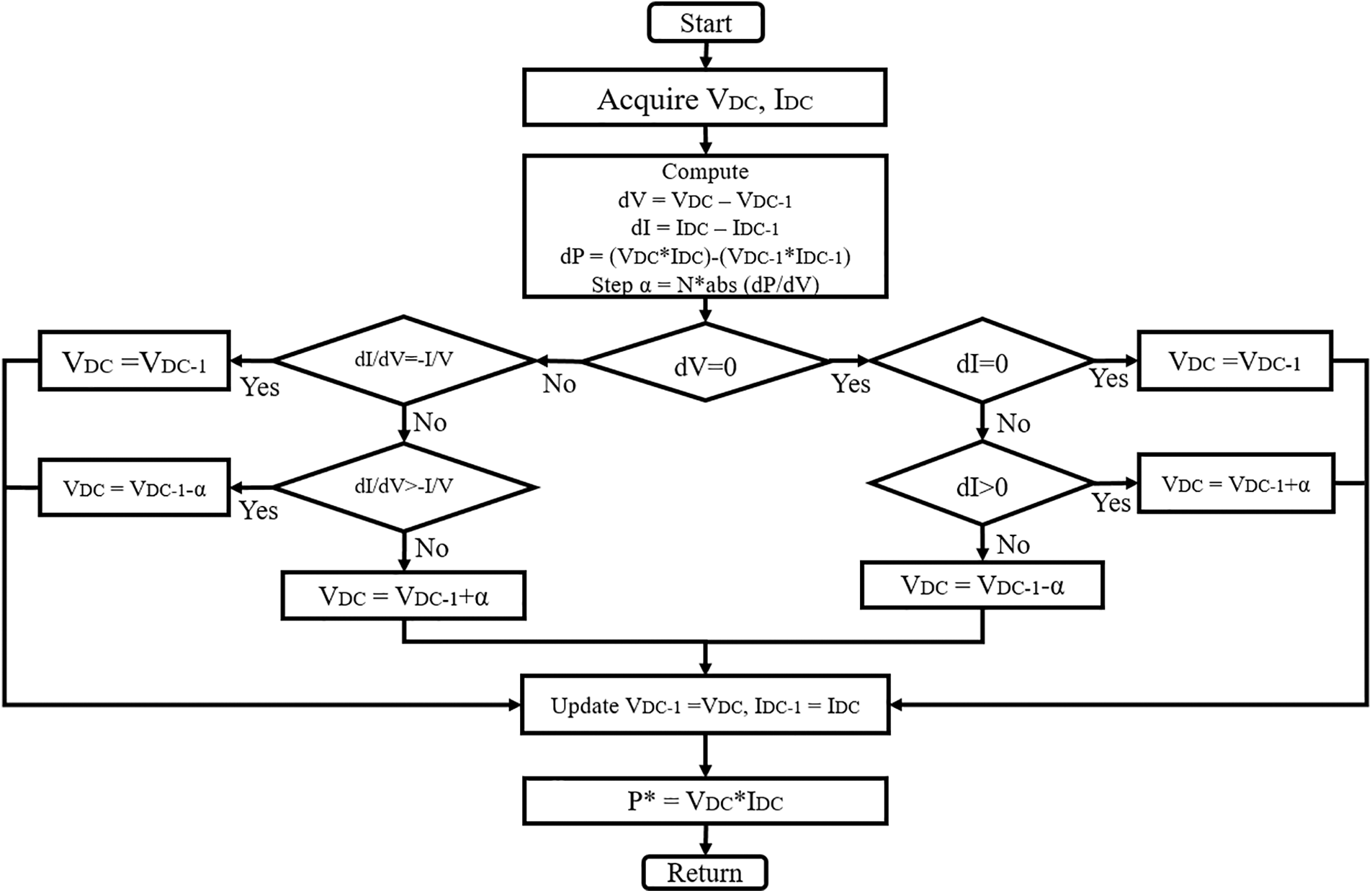
Figure 5: Flowchart of modified VS-InCond algorithm
3 Simulation Results and Analysis
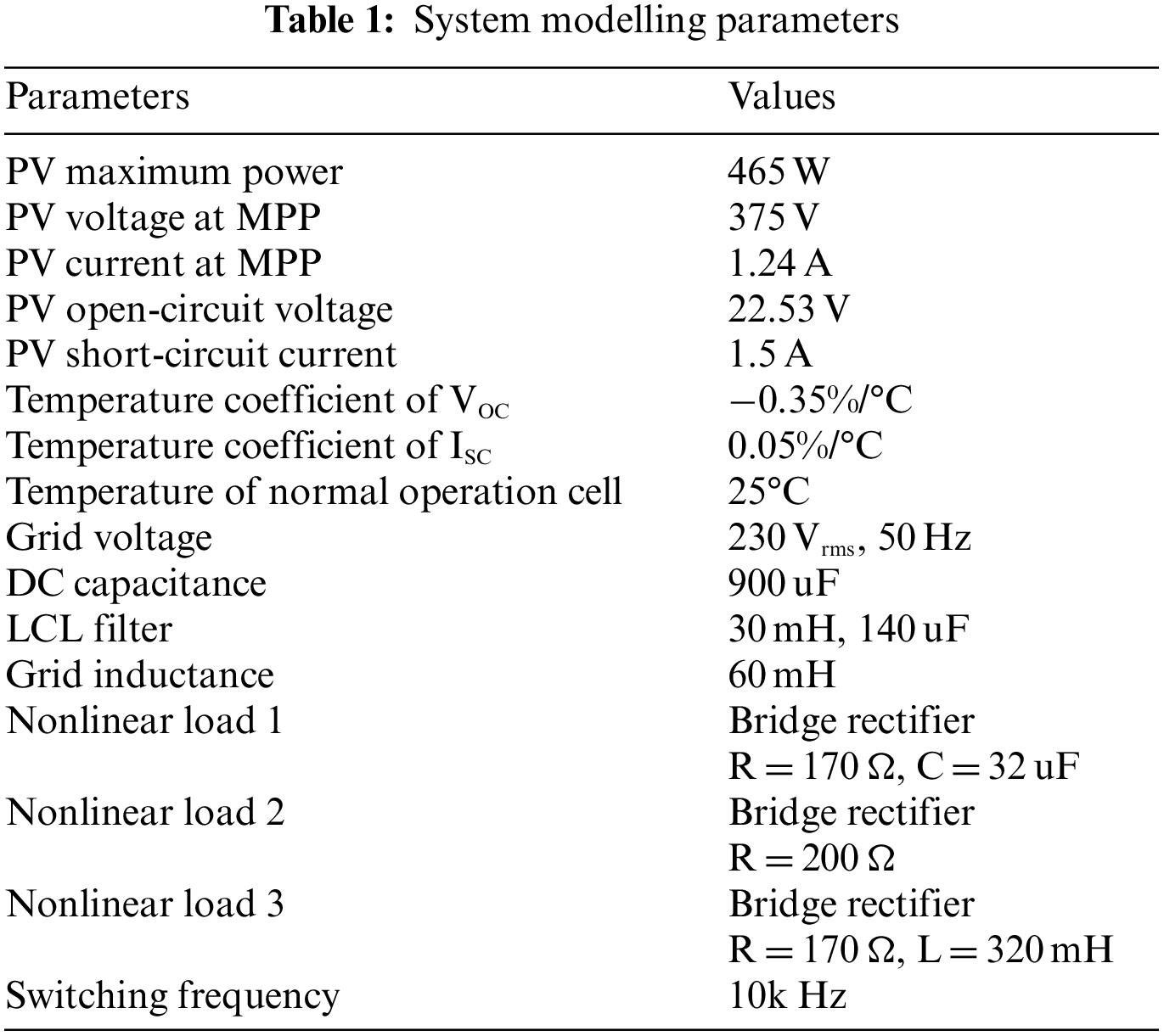
To validate the proposed system, simulation modeling is performed in the MATLAB/SIMULINK environment. The simulations mainly analyze the proposed system performance in terms of active and reactive power compensation and also the THD of grid current during nonlinear load operations with various irradiance fluctuations. The design parameters used are shown in Table 1.
Following standard test conditions (STC), the reference irradiance is set at 1000 W/m2 and 25°C temperature. The measured active powers are 231.81 W for nonlinear load 1, 264.46 W for nonlinear load 2 and 230.55 W for nonlinear load 3 respectively. Figs. 6a–6c show the simulation results in the case of the above nonlinear load applications. As can be seen, the grid voltage (325 V peak) and grid current waveforms (1.42 A peak, 1.20 A peak and 1.41 A peak respectively) are in phase, indicating that the unity power factor is well regulated at the grid side. During this condition, the inverter currents (3.29 A peak lagging by 30.3°, 2.8 A peak and 3.3 A peak leading by 30.6° respectively) supply the nonlinear load. While, the nonlinear load currents are 1.65 A peak leading by 30.3°, 1.63 A peak and 1.65 A peak lagging by 30.6° respectively.
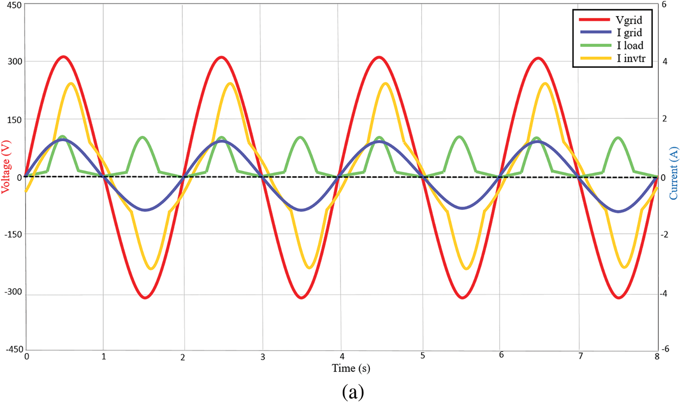
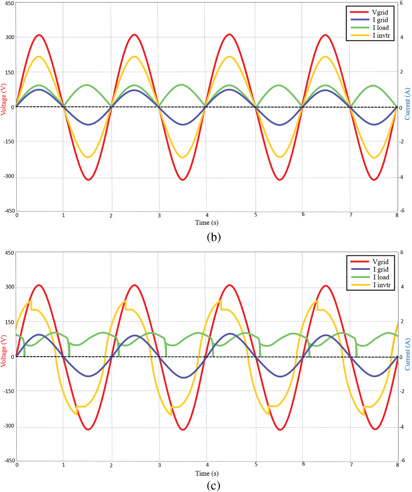
Figure 6: Voltage and current waveforms of the system at STC 1000 W/m2 under (a) nonlinear load 1 (b) nonlinear load 2 (c) nonlinear load 3
In this section, the capability of the proposed controller is tested under varying solar intensities. Fig. 7a demonstrates the system performances when irradiance changes from 800 to 200 W/m2 at 4 s, while the temperature is maintained at 25°C with nonlinear load 1 at 231.81 W. During irradiance 800 W/m2, the inverter (2.64 A peak) supplies the nonlinear load and the active power is also delivered to grid side (0.85 A peak). It can also be seen that the inverter current is severely affected by the nonlinear load, while the grid current is not affected at all due to the effective regulation of the proposed controller. At irradiance 200 W/m2, due to the low irradiance condition, the nonlinear load 1 draws power from the grid (−0.88 A peak) since inverter power (0.63 A peak) is not able to completely meet the load demand.
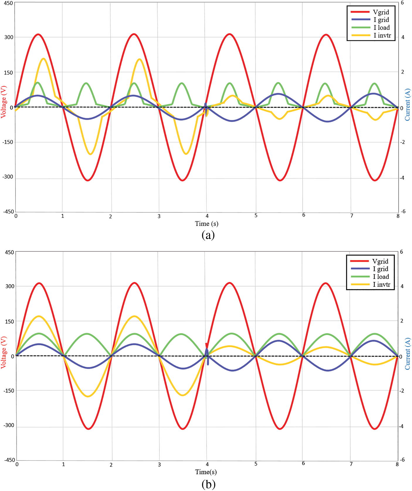
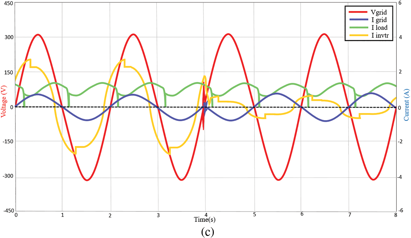
Figure 7: Voltage and current waveforms of the system at 800 and 200 W/m2 with (a) nonlinear load 1 (b) nonlinear load 2 (c) nonlinear load 3
Meanwhile, Fig. 7b shows the simulation result when the proposed system is tested with nonlinear load 2. At irradiance 800 W/m2, the inverter supplies the load with 2.26 A peak current and the surplus is delivered to the grid at 0.64 A peak. At irradiance 200 W/m2, the grid complements the remaining load power at −1.08 A peak current and the inverter only manages to deliver 0.55 A peak current to the load. This is due to the low irradiance on the DC supply side. Fig. 7c shows the output waveform for the nonlinear load 3 testing. At irradiance 800 W/m2, the inverter supplies the load with 2.64 A peak current and the surplus of 0.86 A peak current is delivered to the grid. During low irradiance at 200 W/m2, the inverter only manages to supply the load with 0.63 A peak current, while the remaining current is drawn from the grid at −0.88 A peak. As can be observed, whether resistive, capacitive or inductive nonlinear loads, the proposed controller manages to maintain the unity power factor level at the grid side. The grid side is also not affected by the nonlinear loads. While the inverter current is affected due to the nonlinear load conditions. The proposed controller stabilizes within less than 0.5 s during the transients.
Fig. 8 shows the analysis of active power control of the overall system. Pinverter, Pload and Pgrid are the inverter output active power, load active power and active power injected into the grid or vice versa. Fig. 8a shows the result for nonlinear load 1. At 1000 W/m2, the inverter power supplied by the PV array is about 462 W, while the surplus power delivered to the grid is 230.19 W. When the sunlight intensity changed to 800 W/m2, the inverter power supplied by the PV array is reduced to 370 W with the surplus power to the grid at 138.19 W. During low sunlight intensity condition which occurs at 200 W/m2, a grid power of −143.81 W is taken to supply the nonlinear load 1 (231.81 W). This happens since the load draws higher power than the available inverter power at 88 W. Fig. 8b shows the result for nonlinear load 2 testing. At 1000 W/m2, the inverter power supplied by the PV array is 460 W, while the surplus delivered to the grid is 195.54 W. When sunlight intensity is changed to 800 W/m2, the inverter power supplied by the PV array is 368 W with the surplus power to the grid being 103.54 W. Fig. 8c shows the result for nonlinear load 3 testing. At 1000 W/m2, the inverter power supplied by the PV array is about 460 W. The grid receives 229.45 W and the load absorbs 228.75 W. When the sunlight intensity changed to 800 W/m2, the inverter power supplied by the PV array is about 370 W and the grid takes about 139.45 W. During low sunlight intensity condition which occurs at 200 W/m2, the grid power is at −142.55 W which indicates that the grid partially supplies power to the nonlinear load 3 (at 230.55 W). While the inverter makes up another 88 W to the load. Based on the results, the spike of sudden irradiance changes is only less than 0.5 s for the proposed controller to full operation. These results prove that the proposed controller manages to regulate and control the active and reactive powers between the inverter, nonlinear load and grid.
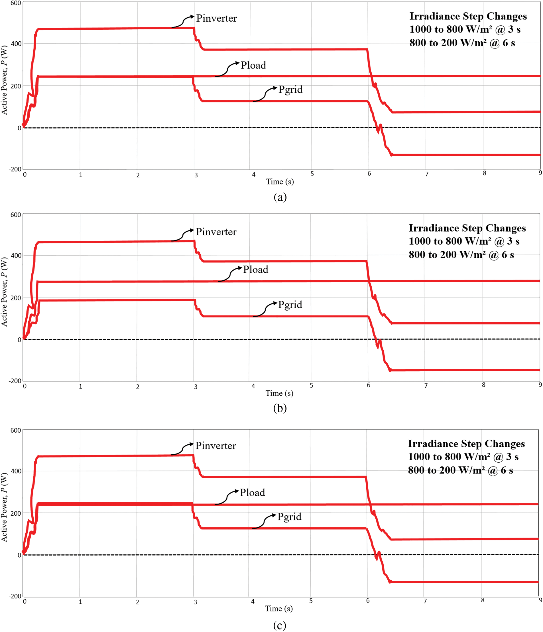
Figure 8: Active power flow of the system at 1000, 800 and 200 W/m2 (a) nonlinear load 1 (b) nonlinear load 2 (c) nonlinear load 3
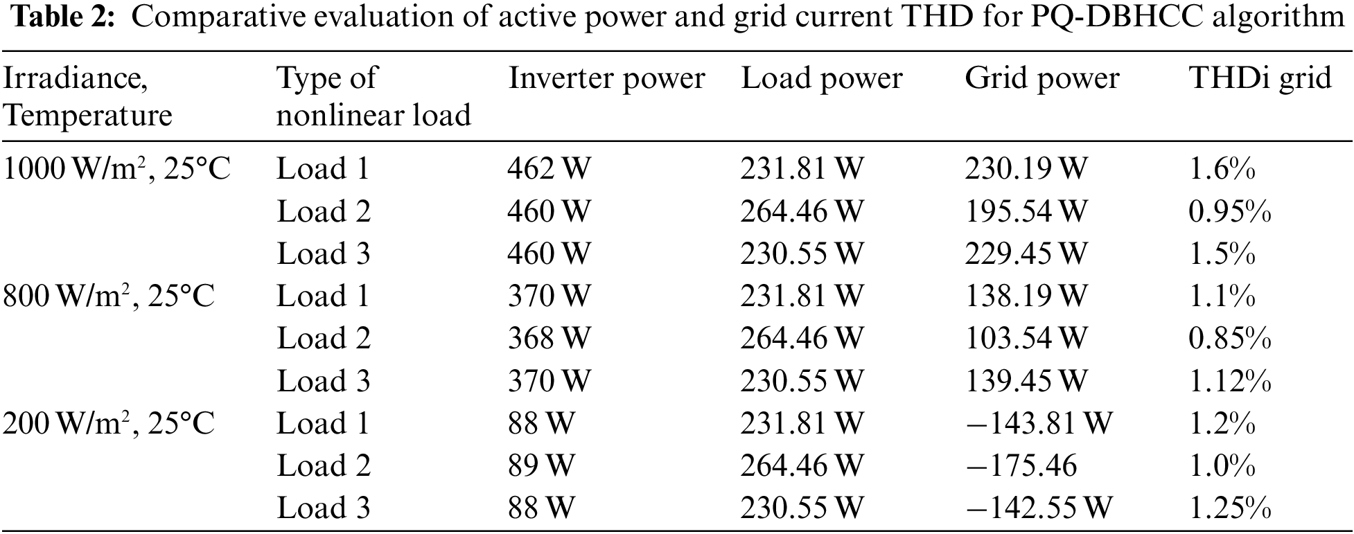
From FFT analyses, the THD values of the grid current are analyze. The THD values are 1.6% for the nonlinear load 1, 0.95% for nonlinear load 2 and 1.5% for nonlinear load 3 respectively. The THD values indicate that the grid current is not affected by the nonlinear load. THDs are well within the specified limits of IEEE 519 standards. The active power compensation and grid current THD comparison for the different type of load and irradiance is presented in Table 2.
3.3 Comparison of the MPPT Algorithm
Fig. 9 shows the MPP can be tracked for less than 1 s during each irradiance change. The modified VS-InCond algorithm can track the MPP within 0.5 s. The steady-state oscillation amplitude is recorded at 465 W when the working point approaches the MPP in the case of 1000 W/m2. When the solar intensity is changed from 1000 W/m2 to 800 W/m2 at 2 s, the steady state oscillation amplitude is about 372 W reached within 1 s. At 5 s, the light intensity drops to 600 W/m2 and the modified algorithm can track the maximum power within less than 0.5 s, the oscillation amplitude is around 184 W. At 7 s, the light intensity drops to 200 W/m2, and it takes 2.5 s for the system to track the MPP again at 90.21 W. The modified VS-InCond algorithm also proves that it remains unchanged after the MPP is reached during irradiance variation.
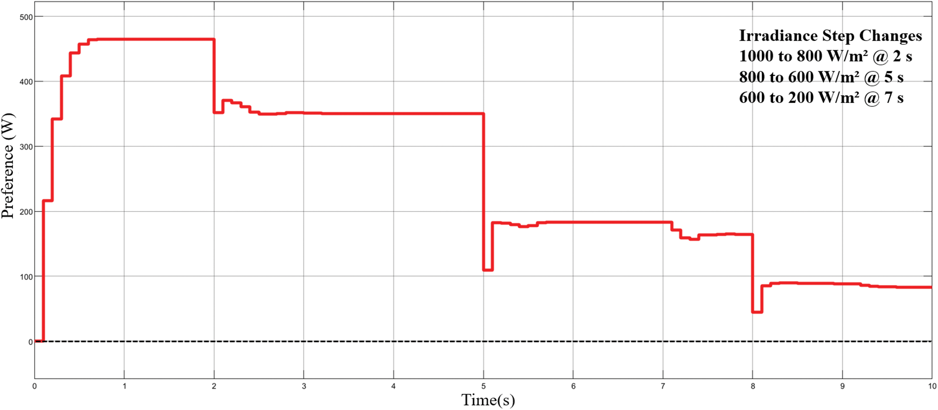
Figure 9: Active power of modified VS-InCond algorithm
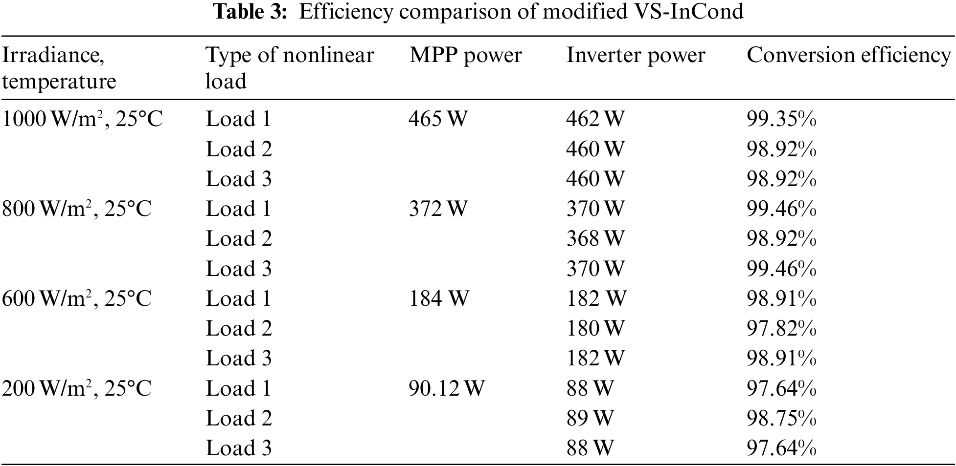
Efficiency is another crucial measure in any power conversion system. The proposed modified VS-InCond is evaluated for its efficiency under tested loads and irradiance changes. Based on PMPP and PINVERTER (as observed in Figs. 8a–8c respectively) the power conversion efficiency can be calculated using Eq. (9) and tabulated in Table 3. At irradiance 1000 W/m2, the efficiency of power conversion for nonlinear load 1 is 99.35%. While, for nonlinear load 2 and load 3, the efficiency of power conversion are 98.92%. Then, at irradiance 800 W/m2, the efficiency of power conversion for nonlinear load 1 and load 3 are 99.46% and for nonlinear load 2 is 98.92%. Whereas, at 600 W/m2, the efficiency of power conversion for nonlinear load 1 and load 3 are 98.91% and for nonlinear load 2 is 97.82%. Lastly, at irradiance 200 W/m2, the power conversion efficiency is 98.75% for nonlinear load 2 and 97.64% for nonlinear load 1 and load 3.
In order to verify the capability of the modified VS-InCond algorithm, comparisons are carried out with the conventional InCond algorithm developed by [12]. Fig. 10 shows that the conventional InCond algorithm takes about 0.5 s to track the MPP at 1000 W/m2 and the oscillation amplitude is range from 465 W to 463 W. whereas, at 800 W/m2, the MPP is track within 0.6 s and the oscillation amplitude is unsettle between 465 to 463 W between 359 to 348 W. Then, when irradiance changes from 800 to 600 W/m2 at 5 s, the new MPP is track within 0.55 s and the oscillation amplitude is range between 183.75 to 183.3 W. At 200 W/m2, the new MPP is track within 1.2 s and the oscillation amplitude is range between 83.7 to 83 W. From the figures, it is observed that when irradiance changes and the oscillation at the MPP is high and difficult to stabilize at the maximum theoretical peak. Comparing the results in Figs. 9 and 10, it can be noticed that the proposed modified VS-InCond algorithm minimizes the oscillations at the MPP. The modified algorithm combines tracking speed and steady-state precision and delivers the desired result, indicating that the proposed control scheme is effectively possible.
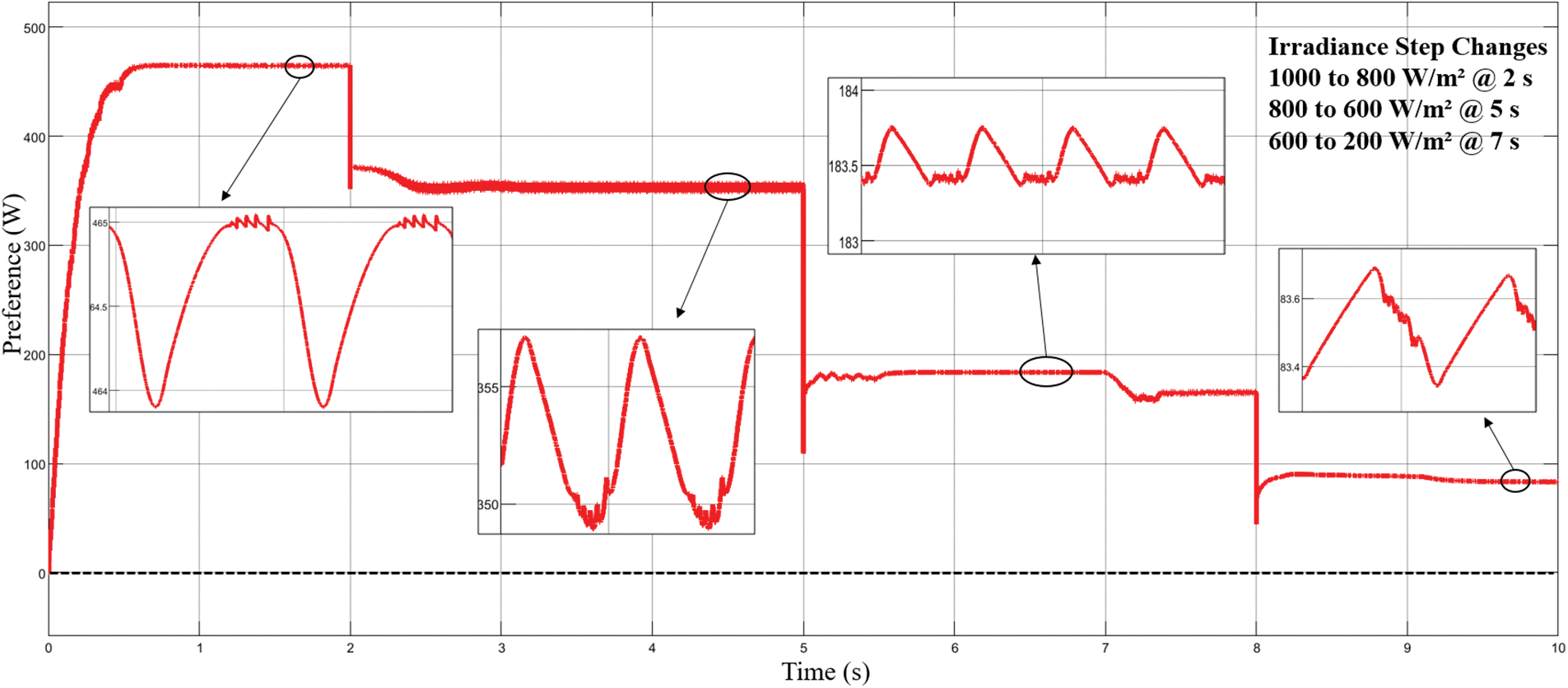
Figure 10: Active power of conventional InCond algorithm
This paper presents the performance of a grid-connected single-phase inverter for nonlinear load applications in PV renewable energy systems. As justified by the simulation findings, the improved current control scheme consisting of modified PQ theory and DBHCC can effectively reduce the voltage distortion of the inverter caused by several types of nonlinear loads, minimize the grid current harmonics within 5% specified limits of IEEE 519 standards and regulate unity power factor at the grid side. The proposed control scheme is also able to deliver a power conversion efficiency of more than 97% based on several irradiance changes modeling. Also by comparing the results of the proposed modified VS-InCond MPPT algorithm with the conventional InCond MPPT algorithm, it is found that the proposed modified VS-InCond MPPT algorithm has superior performance in delivering a stable active power from the PV arrays to the load and the grid network during various irradiance conditions.
Funding Statement: This research was funded by Geran Galakan Penyelidik Muda GGPM-2020-004 Universiti Kebangsaan Malaysia.
Conflicts of Interest: The authors declare that they have no conflicts of interest to report regarding the present study.
References
1. M. Yazdi and F. Yazdi, “A non-linear load sharing method by harmonics spectrum allocation to the inverters,” in Proc. 2019 IEEE PES Innov. Smart Grid Technol. Eur. ISGT-Europe 2019, Bucharest, Romania, pp. 4, 2019. [Google Scholar]
2. V. Rallabandi, O. M. Akeyo and D. M. Ionel, “Modeling of a multi-megawatt grid connected PV system with integrated batteries,” in 2016 IEEE Int. Conf. Renew. Energy Res. Appl. ICRERA 2016, Birmingham, United Kingdom, vol. 5, pp. 1146–1151, 2016. [Google Scholar]
3. A. Talebkhah, M. S. Shadlu and S. Majid Fatemi, “Control strategy of a single phase active power filter with adjustable DC link capacitor voltage for THD reduction in non-linear loads,” in 2019 10th Int. Power Electron. Drive Syst. Technol. Conf. PEDSTC 2019, Shiraz, Iran, pp. 606–611, 2019. [Google Scholar]
4. E. Kabalcı, “Review on novel single-phase grid-connected solar inverters: Circuits and control methods,” Solar Energy, vol. 198, no. January, pp. 247–274, 2020. [Google Scholar]
5. P. K. Pardhi and S. K. Sharma, “Power optimized architecture based converter and Its control for single phase grid-tied solar photovoltaic system,” in 2020 IEEE Int. Conf. Power Electron. Smart Grid Renew. Energy, PESGRE 2020, Kerala, India, pp. 11–16, 2020. [Google Scholar]
6. P. Liu, H. Li, X. Niu and J. Lu, “A novel grid-connected current harmonics control method of single-phase distributed PV with nonlinear local loads based on LADRC,” in Asia-Pacific Power Energy Eng. Conf. APPEEC, Sabah, Malaysia, vol. 2018-Octob, no. 15220710500, pp. 149–154, 2018. [Google Scholar]
7. S. Dasgupta, S. K. Sahoo and S. K. Panda, “A novel current control scheme using lyapunov function to control the active and reactive power flow in a single phase hybrid PV inverter system connected to the grid,” in 2010 Int. Power Electron. Conf.-ECCE Asia-, IPEC 2010, Sapporo, Japan, pp. 1701–1708, 2010. [Google Scholar]
8. K. A. Ogudo and J. W. Makhubele, “Comparative analysis on modulation techniques for a single phase full-bridge inverter on hysteresis current control PWM, sinusoidal PWM and modified sinusoidal PWM,” in icABCD 2019-2nd Int. Conf. Adv. Big Data, Comput. Data Commun. Syst., Winterton, South Africa, pp. 1–7, 2019. [Google Scholar]
9. M. Nisha and M. G. Nisha, “Optimum tuning of photovoltaic system via hybrid maximum power point tracking technique,” Intelligent Automation & Soft Computing, vol. 34, no. 2, pp. 1399–1413, 2022. [Google Scholar]
10. R. Ayop and C. W. Tan, “Design of boost converter based on maximum power point resistance for photovoltaic applications,” Solar Energy, vol. 160, no. August 2017, pp. 322–335, 2018. [Google Scholar]
11. D. Sabaripandiyan, H. Habeebullah Sait and G. Aarthi, “A novel hybrid mppt control strategy for isolated solar pv power system,” Intelligent Automation & Soft Computing, vol. 32, no. 2, pp. 1055–1070, 2022. [Google Scholar]
12. L. Yang, Z. Yunbo, L. Shengzhu and Z. Hong, “Photovoltaic array MPPT based on improved variable step size incremental conductance algorithm,” in Proc. of the 29th Chinese Control and Decision Conf., CCDC 2017, Chongqing, China, pp. 2347–2351, 2017. [Google Scholar]
13. T. Eswara Rao and S. Elango, “Implementation of FPGA based MPPT techniques for grid-connected PV system,” Intelligent Automation & Soft Computing, vol. 35, no. 2, pp. 1783–1798, 2023. [Google Scholar]
14. M. Abu-Zaher, Y. Atia, F. K. Abo-Elyousr and E. El-Zohri, “Experimental realization for PO maximum power point tracking applied for single-stage three-phase grid-connected photovoltaic system,” in 2019 21st Int. Middle East Power Syst. Conf. MEPCON 2019-Proc., Cairo, Egypt, pp. 704–709, 2019. [Google Scholar]
15. IEEE Standards Coordinating Committee 21 on Fuel Cells Photovoltaics Dispersed Generation and Energy Storage, “IEEE recommended practice for utility interface of photovoltaic (PV) systems,” vol. 2000, 2000. [Google Scholar]
16. S. Jena, B. Mohapatra, C. K. Panigrahi and S. K. Mohanty, “Power quality improvement of 1-φ grid integrated pulse width modulated voltage source inverter using hysteresis current controller with offset band,” in ICACCS 2016-3rd Int. Conf. Adv. Comput. Commun. Syst. Bringing to Table, Futur. Technol. from Arround Globe, Coimbatore, India, no. 1, pp. 6, 2016. [Google Scholar]
17. A. Darwish, S. Alotaibi and M. A. Elgenedy, “Current-source single-phase module integrated inverters for PV grid-connected applications,” IEEE Access, vol. 8, pp. 53082–53096, 2020. [Google Scholar]
18. X. Zou, A. Tang, R. Liu and Y. Wang, “Research on MPPT algorithm based on variable step size conductance increment + PI method,” in 2021 IEEE 5th Adv. Inf. Technol. Electron. Autom. Control Conf., Chongqing, China, vol. 2021, no. 1, pp. 829–833, 2021. [Google Scholar]
Cite This Article
 Copyright © 2023 The Author(s). Published by Tech Science Press.
This work is licensed under a Creative Commons Attribution 4.0 International License , which permits unrestricted use, distribution, and reproduction in any medium, provided the original work is properly cited.
 Downloads
 Citation Tools