
 Submit a Paper
 Propose a Special lssue
 Open Access
ARTICLE

Computing and Implementation of a Controlled Telepresence Robot
1 Prince Sattam Bin Abdulaziz University, Al-Kharj, 11942, Saudi Arabia
2 Faculty of Computing and Information Technology, King Abdulaziz University, Jeddah, 21589, Saudi Arabia
3 Department of Mechanical Engineering, The University of Lahore, Lahore, 54000, Pakistan
4 Department of Electrical Engineering, GC University Lahore, Lahore, 54000, Pakistan
* Corresponding Author: Ali A. Altalbe. Email:
Intelligent Automation & Soft Computing 2023, 37(2), 1569-1585. https://doi.org/10.32604/iasc.2023.039124
Received 11 January 2023; Accepted 11 April 2023; Issue published 21 June 2023
 View Full Text
 Download PDF
Abstract
The development of human-robot interaction has been continuously increasing for the last decades. Through this development, it has become simpler and safe interactions using a remotely controlled telepresence robot in an insecure and hazardous environment. The audio-video communication connection or data transmission stability has already been well handled by fast-growing technologies such as 5G and 6G. However, the design of the physical parameters, e.g., maneuverability, controllability, and stability, still needs attention. Therefore, the paper aims to present a systematic, controlled design and implementation of a telepresence mobile robot. The primary focus of this paper is to perform the computational analysis and experimental implementation design with sophisticated position control, which autonomously controls the robot’s position and speed when reaching an obstacle. A system model and a position controller design are developed with root locus points. The design robot results are verified experimentally, showing the robot’s agreement and control in the desired position. The robot was tested by considering various parameters: driving straight ahead, right turn, self-localization and complex path. The results prove that the proposed approach is flexible and adaptable and gives a better alternative. The experimental results show that the proposed method significantly minimizes the obstacle hits.Keywords
In the era of modern days, human-robot interaction is increasing and demanding in many application areas, including healthcare systems and military applications. This is due to the advancement and capability of the robot to perform complex tasks in dangerous and prohibited environments. The evolution of the digital era and smart robotic designs keep simplifying daily routine tasks with fast response and precision. The researchers are working very hard to design such robots, but still, the robots have many limitations in performing various functions. But on the other hand, it has become necessary for humans to involve robots in tasks from remote locations or in harmful situations, e.g., COVID-19. Robots, instead of human beings while sitting in remote locations, execute these scheduled tasks [1–4].
Mobile robots are also extensively used in other applications, such as entertainment, audio-video communication, and remote monitoring. However, the design of many physical parameters, including the maneuverability, controllability, and stability of human-robot interaction, still needs attention [5]. Telepresence robots (TRs) have the facility of a video conferencing display to get in contact with the robot continuously. The application of TRs is found in many areas, including remote offices [2–5], online education for disabled students [6,7], and shopping plazas [8]. Employment of TRs is not easy even though a continuous social presence gets attention daily [5,8,9]. In a hazardous or remote location, precise navigation to avoid obstacles is another challenge, limited due to the camera image resolution [10,11]. To overcome these challenges, researchers work day and night on the control mechanism.
The robot is controlled using the remote controller, which is connected to the device and communicates through the remote location. Although the use of the robot is still increasing, the stability of the control system should be designed appropriately so that the journey will be free of collision [12]. Keeping in mind the development and application of the robot in [12,13] and [14,15], we have developed a speed control method with additional sensors, which give information to control the robot’s speed in detecting the obstacle and getting another safe path. Such a useful design for the robot, which controls the fast and slow motion of the robot through a dense and narrow passage, is the demand of current issues. Much work has been done previously in developing the industrial robot reported in [16–18]. However, as per our knowledge, distance-based speed control has not been developed. This motivated us to design a controller for deploying robots in healthcare and military systems. The MERLIN system usability validation is presented in the proposed research work. The idea is to get the information appropriately and use the system’s acquired knowledge [7,8–11].
The crucial part of the proposed work is to analyze the system parameters and robot behavior and develop a stabilized robot speed by designing a position control system. To facilitate the user, the idea is to create a robot that solves the issue while maintaining a safe distance. To accomplish this task, the main emphasis is to design the speed controller and get validation experimentally. Many approaches are used to solve the same problem with different pros and cons [1,19]. A small mobile robot with the help of chassis is developed. To simplify the design, a microcontroller-based control is proposed, which is implemented to control the robot’s behavior as per the user’s preferences. While developing the controller, actuators and sensors have been recommended in the design, and the system is upgraded [12,20–22]. To get the values using the sensors, we developed the control program. Using the control program, various commands are handled and variable signals are controlled using the actuators. A communication interface is developed to get all the components connected. However, to save space, we are skipping the communication interface information. The communication interface is also a basic feature and can be easily implemented using the adaptor. The adaptor has a user program, making it easy to parametrize the robot fully. The user program is not included in the current paper to save space. The computer also has a wireless interface to operate the robot wirelessly. From these findings, the most optimal settings are determined for the robot. Then, to investigate the robot’s behavior, a scenario is tested, and the real-time implementation of the robot is determined.
A small robot model referred to as HPI Savage 2.1 has been industrialized, as shown in Fig. 1. The vehicle is prepared with Ackermann steering and is controlled on a double track, meaning the robot can be controlled with front wheels. It is a four-wheel derive, and full control is available on each wheel to steer in any direction and control the motion.

Figure 1: Monster truck HPI savage 2.1 with robot attachment
Thus similar settings surmount in the project as in a conventional four-wheel drive vehicle. It monitors that the speed and maneuverability of the robot are coupled. The goal was to equip the auto-MERLIN mobile robot to navigate the desired path and detect and avoid obstacles. A novel control electronic is developed to function the robot, and the idea is to meet the expectations. The auto-MERLIN uses the powerful direct current (DC) three TruckPuller3 of 7.2 V each and the controlling model-equipped servo motor HiTec HS-5745MG. An optical position encoder M101B of Megatron Elektronik AG & Co. drives the motor.
In the recent era, human beings’ social life has depended on technology. Although technologies have greatly improved the lifestyle of human beings, the working place, and social gatherings, more investigation can be done to achieve customer satisfaction and systematic analysis. TRs and autonomous vehicles (AVs) might be attractive alternatives in the human social ecosystem.
In [1], a remote manipulator was implemented, considered the pioneer robotic arm. Implementing these TRs is useful in a hazardous or COVID-19 environment that is inaccessible to humans [23]. In [24], researchers have developed TRs for offices, healthcare systems, and nursing homes. Another useful application is augmented virtual reality, which is useful to simulate the feeling of a human-robot interaction environment. In [25], immersed virtual reality was developed to provide guidelines for user design. Many challenges remain, including the adjustable height [26–30], motion along the slope surface, system stability, and low-speed control [12,31–39].
The well-known application areas of mobile robots include ocean exploration, approaching the moon, implementation in nuclear plants [40,41] and recently during COVID-19 [10,42,43]. It is often hard to repair in such scenarios; therefore, the alternate approach of a mobile robot to do these tasks from remote locations is quite demanding. Besides, the negotiation with the end consumer is condensed to mission provisions, and then automating mobile robots’ communications with experts minimizes. There are many approaches developed by researchers, especially in deciding and controlling the robots [34,35]. Another approach to defining the trajectory control using the software architecture of TR is presented by [20,44–46]. The telepresence robot is utilized in many applications and has shown tremendous results in human-robot interaction [47,48]. A search approach by [49] is proposed. It is easy to satisfy the environmental constraints but with low dynamic probability and high computational complexity. The authors proposed a lattice trajectory technique [50] requiring non-uniform sampling. Another approach suggested by [51] uses the interpolation method, but the results are not optimum, and the track is not smooth.
A more general architecture of the telepresence robot is presented in [24,25]. A TR comprises both software and hardware architectures. It contains the hardware components, e.g., biosensors, which get information from the patient and send that to the consultant at a remote location using the available communication technology [6,10,36]. It also contains such components which can produce the control inputs so that the robot can move in a stable position using the actuator connected to it. These actuators control the hardware actions, e.g., motion, speed, and position [37–39]. The presented work focuses on the identification and stabilization of the TR and the development of micro-controller-based architecture. The fundamental responsibility of the design is to control the driving behavior and avoid an obstacle during the whole track of the TR. The design also contains the module with the best driving path, called the decision-making module. The function of this module is to provide the best path and safe driving with obstacle avoidance control. The term “maneuver” is most likely utilized in the literature to describe path planning. Still, to have more clarity and consistency, the term “behavior” is employed to label the whole journey of the presented research article. According to the activities generated by the mini-computer in computing, the other independent attributes like position, trajectory, orientation, and speed are considered. More general techniques are presented in [52–55].
3 Controller Design and Development
The position controller to be set now completes the control of the drive train. The position controller is superimposed on the velocity controller, enabling the robot to move to a specific position on a trajectory defined by the steering. Fig. 2 shows the position control loop.
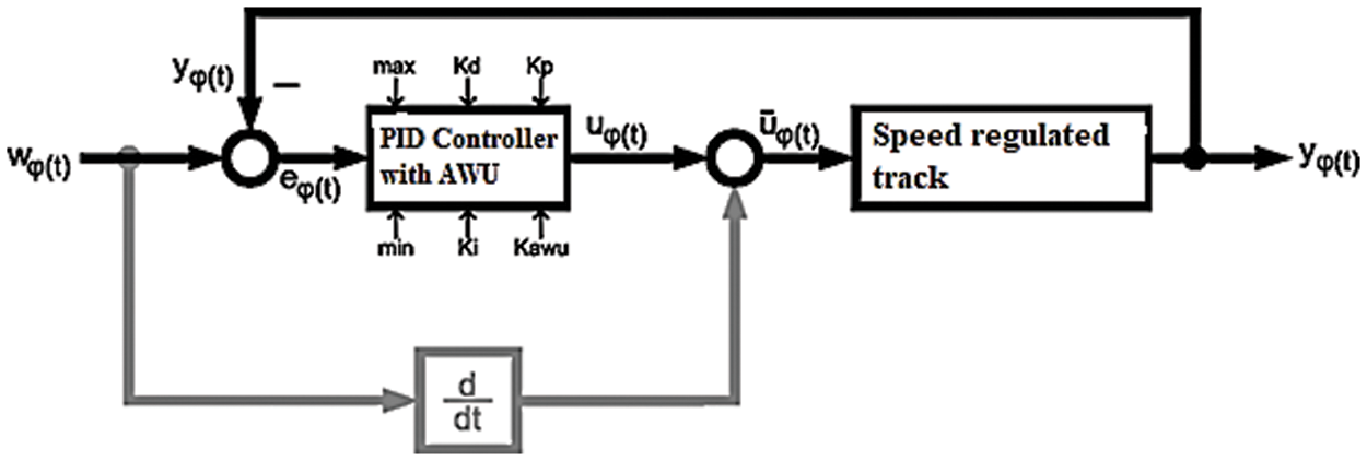
Figure 2: Drive position controller
The block diagram shows that the controller’s manipulated variable
From Fig. 2, it is known that the system to be controlled has an integrator that forms the position from the speed. As a result, the segment has a pole at the origin of the complex s-plane from the outset. Therefore, no integral component should be used with the controller. It will place a second pole at the origin of the complex s-plane, making the system unstable since if the controller gain were increased, and the two integrator poles would immediately move to the right side of the real axis when looking at the root locus. A differential component should also be avoided since it makes the system jumpable concerning the position. This would result in high speeds and accelerations, which the track cannot handle. It, therefore, makes sense to design the position controller as a pure proportional controller. The transfer function of the position controller is thus
The controlled system is the speed control circuit, according to Eq. (2), whereby the additional integrator in the drive must also be considered.
The transfer function of the open position control loop is, therefore
For the specifically calculated speed controller, the result for the open loop control is
Fig. 3 shows the associated root locus curve.

Figure 3: Root locus of the position controller
It seems sensible to set the gain
3.1 Step Response of Controller
Fig. 4 shows the step response of the linear controller model with a setpoint jumps from 0 to 1000 EncImp at time t = 0. The position controller moves the robot very quickly to its target position, which is reached precisely despite the exclusive use of a proportional controller. All manipulated variable limitations were ignored in this step response. However, this does not pose a major problem since the setpoint speed of the robot is only changed in a ramped manner during operation. The accelerations, therefore, remain at an acceptable level. The most important feature of the step response is that the setpoint is reached quickly without significant overshoots.

Figure 4: Step response of the position controller (linear model)
Finally, as for the speed controller, simulations are also carried out for the position controller on a model that is as realistic as possible. No step response is examined this time, but the target speed is changed ramp-like, as shown in Fig. 5. The speed curve is intended to describe a realistic scenario.

Figure 5: Target speed of the robot for the simulation
After the analysis of the speed controller follows the analysis of the position controller. For this purpose, the robot should approach a target straight ahead, which is 10000 EncImp away. It takes around 25 s, but the robot can record a maximum of 20 s, as shown in Fig. 6.

Figure 6: Velocity for a given trapezoidal profile with disturbance
Also, it is difficult to synchronize the start of the step response with the beginning of the recording, so the recording time is also lost here. However, the recording contains all the information relevant to the analysis. The setpoint ramp was added later and can be slightly different in time. However, this only slightly influences the following error and, thus, the correction time in this analysis. The measured values are smoothed with a PT1 element with a time constant of 20 ms.
From the figure, it can be seen that the robot follows the target speed ramp very well. There are slight starting difficulties due to the gear play, but these are quickly overcome. After 12 s, the robot drives over a bump again, causing disturbances in the actual speed. The braking process is still slightly indicated, but then the recording ends. The most important finding is that the actual value can follow the setpoint very well, does not overshoot, and the tendency of the speed controller to oscillate does not increase due to the position controller. The target is also usually reached with an error of less than ±20 EncImp, corresponding to around ±1 cm.
The constant of proportionality for the conversion between the unit encoder pulses (EncImp) and meters (m) was determined. The robot drove straight ahead 10000 EncImp. The start and end points were marked, and the route was measured afterward.
The proportionality constant k can be determined. The length of the distance travelled, measured with a ruler, was 5.8 m in the test. The constant of proportionality k results accordingly
The simulation is carried out once without and once with speed pre-control. Fig. 7 shows the simulation result of the position control loop without pre-control. The target position u results from integrating the target speed over time and the actual position y and error. It can be seen that the control loop reaches the setpoint with a delay of approximately 1 s without overshooting.

Figure 7: Simulation result of the position control loop without pre-control
Now the same simulation is carried out with active speed pre-control. Figs. 8 and 9 show the simulation result, with Fig. 9 showing an enlargement of Fig. 8. The error has been increased by 10.

Figure 8: Simulation result of the position control loop with pre-control

Figure 9: Simulation result of the position control loop with pre-control (enlargement)
It can be seen that the error is only present in the kinks of the speed profile and is corrected very quickly. The control circuit’s control behavior is almost exclusively affected by the pre-control. For the most part, the position controller is only used to compensate for disturbance variables.
The robot records the relevant data and then displays it vividly. The data from the results are measured using the microcontroller, and the results of the speed controller are presented. It can be seen that there is small jitter found in the sampled values, and this is due to the non-synchronized sampling rate. The results are often replicated in small jumps in the curves.
Next, partial trajectories are examined. First, straight-ahead driving is considered, with both the position and the orientation being controlled. Fig. 10 shows the distance covered and the orientation of the robot. Fig. 11 shows the position of the robot in the X-Y plane. From the graphs, it should be noted that the measured values were not necessarily recorded evenly.

Figure 10: Kinematics of the robot

Figure 11: Driven trajectory
During the test drive in the laboratory, the robot covered a distance of 4 m in a northeast direction. The orientation for this direction is around −57°. The graph of the distance travelled shows the typical S-curve that a trapezoidal speed profile creates. The end value of 4 m = 6896 EncImp is reached very well. The orientation fluctuates around the −57° mark, the target value. All in all, the deviation from the target value is quite small at around 10°.
In particular, the steering is non-linear, the zero point is not exactly correct, and it is stiff, to make matters worse. This, of course, makes it extremely difficult to regulate the orientation. However, looking at the trajectory driven, you can see that the robot drove very straight. The length of the trajectory also corresponds to the desired 4 m. The controllers have thus proven their skills in this scenario.
In the next scenario, simple cornering is considered. This is a right-hand curve, with an angle of 84° (−64° ... −148°) swept over a distance of 3 m = 5172 EncImp. This roughly corresponds to a quarter of a circle. Fig. 12 shows the distance covered, the target, and the actual value of the robot’s orientation. Fig. 13, however, shows the driven trajectory in the X-Y plane. The circle on which the robot moves was reconstructed from three randomly selected trajectory points.

Figure 12: Kinematics of the robot

Figure 13: Driven trajectory
The graph of the distance covered is shown in Fig. 13. It is hard to see any significant difference in driving straight ahead. The same S-shape can be seen again. The orientation, on the other hand, looks very different. If you first look at the target value, you can guess it changes linearly with the distance covered. It has the same S pattern as the position graph. The actual value curve follows the setpoint curve quite well.
The trajectory graph shown in Fig. 13 that was driven (black line) shows that the robot moved on a very nice circular path. The subsequently calculated red circle, calculated from three randomly selected trajectory points, serves as a comparison in the diagram. It deviates only slightly from the blue target circle. So the controllers of the robot seem to work well in principle.
After automatically calibrating the magnetometer, the robot was driven in a circle across the corridor of the EE building of the University of King Abdulaziz. Test one was gone clockwise and one counterclockwise. A Google maps aerial photograph is used to record the position of the resulting trajectories. The trajectory was recorded by having the aspect ratio and orientation of the building. The result of the self-localization is shown in Fig. 14.

Figure 14: Self-estimates of robot position
From Fig. 14, there is a red and blue colour, and each colour represents a trajectory direction-wise, either clock or anti-clock. The red measurement is recorded for the clockwise trajectory, and the blue colour trajectory denotes the counterclockwise direction. From the results, it is shown that there is a small deviation in each trajectory. The deviation is due to the accumulation of past value in the present value. To do further analysis, the error accumulation keeps adding, and the results deviate from the present value. However, the error can be further reduced by having more calibration and control, but the residual value improvement is not that much, and the computational complexity is kept increasing. The results also show that the first three tracks are exactly parallel to each, and a slight deviation is found in the fourth track, which can be improved.
As said above, there are many causes of occurring errors in the trajectories. The very first reason could be poor magnetometer calibration. The variation in the calibration is due to the rotation of the angle or other interferences. The interference could be due to the other sources of interference in the building, which are the causes of deviation. These sources include the transmission lines, waves from undesired interfering sources, and the railing stairs could be examples of all these sources.
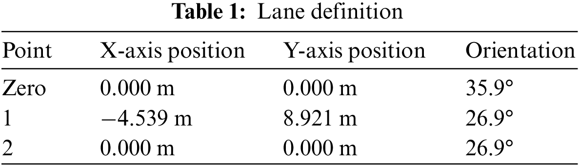
The test is performed to see the robot’s behavior over a complex path. The University campus corridor was chosen as the test track. A distance of 10 m was chosen as a straight path from the Zero point and then returned to the Zero point; the robot uses the same track. The path definition is given in Table 1.
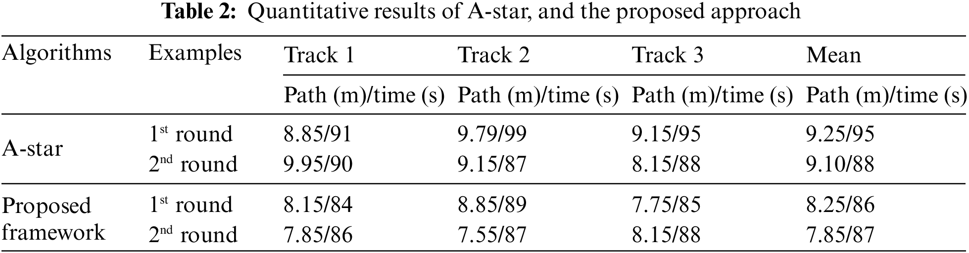
An experiment was conducted to compare the proposed approach and the A-star algorithm. The results show that the proposed system better covers the distance from the doctor’s office to patient A room. A cumulative distance covered by each approach is noted in Table 2.
The target and the exact track are shown in Fig. 15. By exact path, we mean the exact coordinated covered recorded by the TR and referred to as the target path. However, the actual path is often not given the path to be covered, which is not covered without special recording devices. The target paths are also marked to get the results.

Figure 15: Calculated and driven trajectories
From Fig. 15, it is observed that the target path agrees well with the exact path. However, only a slit deviation is observed around the path. The deviation is due to the TR present pose and is evaluated using the present value. Still, these values are not corresponding to the present value, and it could be the results due to the past value stored in the memory of TR. It is well observed that the target path is well maintained.
To add more path, a track is selected from the doctor’s office to the patient ward in an outdoor environment, as shown in Fig. 16. Total distance of 15 meters was covered, and the whole path covered by the TR is shown in Fig. 16, which shows a successful self-localization.

Figure 16: Experimental study of the robot used in a healthcare system
The purpose of the research is to develop a well-maintained telepresence robot (TR) which is used in the healthcare environment. The system identification model is used to design the control parameters of the TR. A perfect design of TR is proposed with the speed controller, and a full analysis is provided. Theoretical models of the robot mechanics with position control were also created. These include the digital variants of basic control engineering elements, analog to digital converter evaluation and characteristic curve linearization. In the case of the robot, the high-level controller is a mini-computer running the application program. This was, of course, also developed but not included in the current paper to save space. To this end, controlled test drives were undertaken, and the results were evaluated. The settings for the robot could then be determined from these. Finally, the ideally adjusted robot was checked for its desired behavior. A few tests were taken to validate the proposed design: complex path is driven, self-localization, left and right turn, and observing the robot’s behavior. The simulation results showed that the TR trajectory was well maintained during a full course.
A system model and a position controller design are developed with root locus points. The design robot results are verified experimentally, showing the robot’s agreement and control in the desired position. The robot was tested by considering various parameters: driving straight ahead, right turn, self-localization, and complex path. The results of the maneuverability, controllability, and stability show that the proposed design is well-developed, cost-effective and has a fast response time. Our results showed that the telepresence robot equipped with the DRL approach could successfully navigate the environment and interact with objects for 30 s without operating signals from the teleoperator during communication delays. Furthermore, the telepresence robot outperformed traditional telepresence robots regarding user experience, maneuvering in a remote environment, and obstacle avoidance. The expansion to future work is possible in one of the following areas; other useful technologies can be integrated, other application areas, and development of different efficient algorithms.
Acknowledgement: Authors would like to thank the Ministry of Education in Saudi Arabia for funding this research work.
Funding Statement: This work was supported by the Deanship of Scientific Research at Prince Sattam bin Abdulaziz University under the research project (PSAU/2023/01/23001).
Conflicts of Interest: The authors declare that they have no conflicts of interest to report regarding the present study.
References
1. R. Li, H. Wang and Z. Liu, “Survey on mapping human hand motion to robotic hands for teleoperation,” IEEE Transactions on Circuits and Systems for Video Technology, vol. 32, no. 5, pp. 2647–2665, 2021. [Google Scholar]
2. N. Lazzeri, D. Mazzei, L. Cominelli, A. Cisternino and D. E. D. Rossi, “Designing the mind of a social robot,” Applied Sciences, vol. 8, no. 2, pp. 1–18, 2018. [Google Scholar]
3. S. Sun, X. Zhao, Q. Li and M. Tan, “Inverse reinforcement learning-based time-dependent A* planner for human-aware robot navigation with local vision,” Advanced Robotics, vol. 34, no. 13, pp. 1–14, 2020. [Google Scholar]
4. A. D. Sanders, “Using self-reliance factors to decide how to share control between human powered wheelchair drivers and ultrasonic sensors,” IEEE Transactions on Neural Systems and Rehabilitation Engineering, vol. 25, no. 8, pp. 1221–1229, 2016. [Google Scholar] [PubMed]
5. I. O. Ogunrinde, C. F. Adetu, C. A. Moore Jr, R. G. Roberts and K. McQueen, “Experimental testing of bandstop wave filter to mitigate wave reflections in bilateral teleoperation,” Robotics, vol. 9, no. 2, pp. 1–24, 2020. [Google Scholar]
6. S. G-Climent, A. Garzo, M. N. M-Alcaraz, P. C-Adam, J. A. Ruano et al., “A usability study in patients with stroke using MERLIN, a robotic system based on serious games for upper limb rehabilitation in the home setting,” Journal of Neuroengineering and Rehabilitation, vol. 18, no. 1, pp. 1–16, 2021. [Google Scholar]
7. G. G. Muscolo, S. Marcheschi, M. Fontana and M. Bergamasco, “Dynamics modeling of human-machine control interface for underwater teleoperation,” Robotica, vol. 39, no. 4, pp. 618–632, 2021. [Google Scholar]
8. M. Karimi, C. Roncoli, C. Alecsandru and M. Papageorgiou, “Cooperative merging control via trajectory optimization in mixed vehicular traffic,” Transportation Research Part C: Emerging Technologies, vol. 116, no. 1, pp. 1–28, 2020. [Google Scholar]
9. A. Shahzad and H. Roth, “Teleoperation of mobile robot using event based controller and real time force feedback,” in Proc. Int. Workshops on Electrical and Computer Engineering Subfields, Istanbul, Turkey, pp. 7–12, 2014. [Google Scholar]
10. A. Shahzad, R. Al-jarrah and H. Roth, “Telecontrol of AutoMerlin robot by employing fuzzy logic,” International Journal of Mechanical Engineering and Robotics Research (IJMERR), vol. 5, no. 1, pp. 17–22, 2016. [Google Scholar]
11. O. Kitazawa, T. Kikuchi, M. Nakashima, Y. Tomita, H. Kosugi et al., “Development of power control unit for compact-class vehicle,” SAE International Journal of Alternative Powertrains, vol. 5, no. 2, pp. 278–285, 2016. [Google Scholar]
12. F. J. R-Lera, V. M-Olivera, M. Á. C-González and F. M-Rico, “HiMoP: A three-component architecture to create more human-acceptable social-assistive robots,” Cognitive Processing, vol. 19, no. 2, pp. 233–244, 2018. [Google Scholar]
13. A. Shahzad, M. Salahudin and I. Hussain, “AutoMerlin mobile robot’s bilateral telecontrol with random delay,” 3C Technologia, vol. 1, no. 1, pp. 179–191, 2019. [Google Scholar]
14. P. Stotko, S. Krumpen, M. B. Hullin, M. Weinmann and R. Klein, “SLAMCast: Large-scale, real-time 3D reconstruction and streaming for immersive multi-client live telepresence,” IEEE Transactions on Visualization and Computer Graphics, vol. 25, no. 5, pp. 2102–2112, 2019. [Google Scholar] [PubMed]
15. L. Li, Z. Liu, Z. Ma, X. Liu, J. Yu et al., “Adaptive neural learning finite-time control for uncertain teleoperation system with output constraints,” Journal of Intelligent & Robotic Systems, vol. 105, no. 4, pp. 1–16, 2022. [Google Scholar]
16. L. Thomas, T. C. Lueth, U. Rembold and H. Woern, “A distributed control architecture for autonomous mobile robots-implementation of the Karlsruhe Multi-Agent Robot Architecture (KAMARA),” Advanced Robotics, vol. 12, no. 4, pp. 411–431, 1997. [Google Scholar]
17. R. W. S. M. de Oliveira, R. Bauchspiess, L. H. S. Porto, C. G. de Brito, L. F. C. Figueredo et al., “A robot architecture for outdoor competitions,” Journal of Intelligent & Robotic Systems, vol. 99, no. 3, pp. 629–646, 2020. [Google Scholar]
18. A. Shahzad and H. Roth, “Bilateral telecontrol of AutoMerlin mobile robot with fix communication delay,” in Proc. IEEE Int. Conf. on Automation, Quality and Testing, Robotics, Cluj-Napoca, Romania, pp. 1–6, 2016. [Google Scholar]
19. G. Gorjup, A. Dwivedi, N. Elangovan and M. Liarokapis, “An intuitive, affordances oriented telemanipulation framework for a dual robot arm hand system: On the execution of bimanual tasks,” in Proc. IEEE/RSJ Int. Conf. on Intelligent Robots and Systems (IROS), Macau, China, pp. 3611–3616, 2019. [Google Scholar]
20. F. Cuesta, A. Ollero, B. C. Arrue and R. Braunstingl, “Intelligent control of nonholonomic mobile robots with fuzzy perception,” Fuzzy Sets and Systems, vol. 134, no. 1, pp. 47–64, 2003. [Google Scholar]
21. A. Ahmadzadeh, A. Jadbabaie, V. Kumar and G. J. Pappas, “Multi-UAV cooperative surveillance with spatio-temporal specifications,” in Proc. of the 45th IEEE Conf. on Decision and Control, San Diego, USA, pp. 5293–5298, 2006. [Google Scholar]
22. S. G. Anavatti, S. L. Francis and M. Garratt, “Path-planning modules for autonomous vehicles: Current status and challenges,” in Proc. Int. Conf. on Advanced Mechatronics, Intelligent Manufacture, and Industrial Automation (ICAMIMIA), Surabaya, Indonesia, pp. 205–214, 2015. [Google Scholar]
23. R. Alami, R. Chatila, S. Fleury, M. Ghallab and F. Ingrand, “An architecture for autonomy,” The International Journal of Robotics Research, vol. 17, no. 4, pp. 315–337, 1998. [Google Scholar]
24. A. Shahzad, R. Al-jarrah and H. Roth, “Teleoperation of AutoMerlin by inculcating FIN algorithm,” International Journal of Mechanical Engineering and Robotics Research (IJMERR), vol. 5, no. 1, pp. 1–5, 2016. [Google Scholar]
25. A. Shahzad and H. Roth, “Bilateral telecontrol of AutoMerlin mobile robot,” in Proc. 9th IEEE Int. Conf. on Open-Source Systems and Technologies, Lahore, Pakistan, pp. 179–191, 2015. [Google Scholar]
26. A. Naceri, J. Elsner, M. Tröbinger, H. Sadeghian, L. Johannsmeier et al., “Tactile robotic telemedicine for safe remote diagnostics in times of Corona: System design, feasibility and usability study,” IEEE Robotics and Automation Letters, vol. 7, no. 4, pp. 10296–10303, 2022. [Google Scholar] [PubMed]
27. S. G. Rozevink, C. K. V. D. Sluis, A. Garzo, T. Keller and J. M. Hijmans, “HoMEcare aRm rehabiLItatioN (MERLINTelerehabilitation using an unactuated device based on serious games improves the upper limb function in chronic stroke,” Journal of NeuroEngineering and Rehabilitation, vol. 18, no. 1, pp. 1–12, 2021. [Google Scholar]
28. K. Schilling, “Tele-maintenance of industrial transport robots,” IFAC Proceedings Volumes, vol. 35, no. 1, pp. 139–142, 2002. [Google Scholar]
29. A. Ahmad and M. A. Babar, “Software architectures for robotic systems: A systematic mapping study,” Journal of Systems and Software, vol. 122, no. 1, pp. 16–39, 2016. [Google Scholar]
30. O. Sharma, N. C. Sahoo and N. B. Puhan, “Recent advances in motion and behavior planning techniques for software architecture of autonomous vehicles: A state-of-the-art survey,” Engineering Applications of Artificial Intelligence, vol. 101, no. 1, pp. 1–19, 2021. [Google Scholar]
31. J. Ziegler, M. Werling and J. Schroder, “Navigating car-like robots in unstructured environments using an obstacle sensitive cost function,” in Proc. IEEE Intelligent Vehicles Symp., Eindhoven, Netherlands, pp. 787–791, 2008. [Google Scholar]
32. M. A. G-Santamarta, F. J. R-Lera, C. A-Aparicio, A. M. G-Higueras and C. F-Llamas, “MERLIN a cognitive architecture for service robots,” Applied Sciences, vol. 10, no. 17, pp. 1–17, 2020. [Google Scholar]
33. J. Shao, G. Xie, J. Yu and L. Wang, “Leader-following formation control of multiple mobile robots,” in Proc. IEEE Int. Symp. on, Mediterrean Conf. on Control and Automation Intelligent Control, Limassol, Cyprus, pp. 808–813, 2005. [Google Scholar]
34. M. Faisal, R. Hedjar, M. Al-Sulaiman and K. Al-Mutib, “Fuzzy logic navigation and obstacle avoidance by a mobile robot in an unknown dynamic environment,” International Journal of Advanced Robotic Systems, vol. 10, no. 1, pp. 1–7, 2013. [Google Scholar]
35. F. Favarò, S. Eurich and N. Nader, “Autonomous vehicles’ disengagements: Trends, triggers, and regulatory limitations,” Accident Analysis & Prevention, vol. 110, no. 1, pp. 136–148, 2018. [Google Scholar]
36. S. Gopalswamy and S. Rathinam, “Infrastructure enabled autonomy: A distributed intelligence architecture for autonomous vehicles,” in Proc. IEEE Intelligent Vehicles Symp. (IV), Changshu, China, pp. 986–992, 2018. [Google Scholar]
37. J. F. Allen, “Towards a general theory of action and time,” Artificial Intelligence, vol. 23, no. 2, pp. 123–154, 1984. [Google Scholar]
38. H. Hu, J. M. Brady, J. Grothusen, F. Li and P. J. Probert, “LICAs: A modular architecture for intelligent control of mobile robots,” in Proc. IEEE/RSJ Int. Conf. on Intelligent Robots and Systems. Human Robot Interaction and Cooperative Robots, Pittsburgh, USA, pp. 471–476, 1995. [Google Scholar]
39. W. Zhang, H. Cheng, L. Zhao, L. Hao, M. Tao et al., “A gesture-based teleoperation system for compliant robot motion,” Applied Sciences, vol. 9, no. 24, pp. 1–18, 2019. [Google Scholar]
40. Y. -P. Su, X. -Q. Chen, T. Zhou, C. Pretty and G. Chase, “Mixed-reality-enhanced human-robot interaction with an imitation-based mapping approach for intuitive teleoperation of a robotic arm-hand system,” Applied Sciences, vol. 12, no. 9, pp. 1–17, 2022. [Google Scholar]
41. W. Zhao, Y. Gao, T. Ji, X. Wan, F. Ye et al., “Deep temporal convolutional networks for short-term traffic flow forecasting,” IEEE Access, vol. 7, no. 1, pp. 114496–114507, 2019. [Google Scholar]
42. K. J. Schilling and M. P. Vernet, “Remotely controlled experiments with mobile robots,” in Proc. 34th IEEE Southeastern Symp. on System Theory, Huntsville, USA, pp. 71–74, 2002. [Google Scholar]
43. T. -K. Moon and T. -Y. Kuc, “An integrated intelligent control architecture for mobile robot navigation within sensor network environment,” in Proc. IEEE/RSJ Int. Conf. on Intelligent Robots and Systems (IROS), Sendai, Japan, pp. 565–570, 2004. [Google Scholar]
44. S. Lefèvre, D. Vasquez and C. Laugier, “A survey on motion prediction and risk assessment for intelligent vehicles,” ROBOMECH Journal, vol. 1, no. 1, pp. 1–14, 2014. [Google Scholar]
45. S. Behere and M. Törngren, “A functional reference architecture for autonomous driving,” Information and Software Technology, vol. 73, no. 1, pp. 136–150, 2016. [Google Scholar]
46. A. Carvalho, S. Lefévre, G. Schildbach, J. Kong and F. Borrelli, “Automated driving: The role of forecasts and uncertainty—A control perspective,” European Journal of Control, vol. 24, no. 1, pp. 14–32, 2015. [Google Scholar]
47. P. Liu, B. Paden and U. Ozguner, “Model predictive trajectory optimization and tracking for on-road autonomous vehicles,” in Proc. 21st IEEE Int. Conf. on Intelligent Transportation Systems (ITSC), Maui, USA, pp. 3692–3697, 2018. [Google Scholar]
48. T. Weiskircher, Q. Wang and B. Ayalew, “Predictive guidance and control framework for (semi-) autonomous vehicles in public traffic,” IEEE Transactions on Control Systems Technology, vol. 25, no. 6, pp. 2034–2046, 2017. [Google Scholar]
49. T. M. Howard, C. J. Green, A. Kelly and D. Ferguson, “Statespace sampling of feasible motions for high-performance mobile robot navigation in complex environments,” Journal of Field Robotics, vol. 25, no. 6–7, pp. 325–345, 2008. [Google Scholar]
50. S. Wang, “State lattice-based motion planning for autonomous on-roaddriving,” Ph.D. Thesis, Freie Universit at Berlin, 2015. [Google Scholar]
51. M. Brezak and I. Petrovi, “Real-time approximation of clothoids withbounded error for path planning applications,” IEEE Transactions on Robotics, vol. 30, no. 2, pp. 507–515, 2014. [Google Scholar]
52. S. Mahajan and A. K. Pandit, “Hybrid method to supervise feature selection using signal processing and complex algebra techniques,” Multimedia Tools and Applications, vol. 82, no. 1, pp. 8213–8234, 2023. [Google Scholar]
53. S. Mahajan, L. Abualigah, A. K. Pandit and M. Altalhi, “Hybrid Aquila optimizer with arithmetic optimization algorithm for global optimization tasks,” Soft Computing, vol. 26, no. 10, pp. 4863–4881, 2022. [Google Scholar]
54. S. Mahajan and A. K. Pandit, “Image segmentation and optimization techniques: A short overview,” Medicon Eng Themes, vol. 2, no. 2, pp. 47–49, 2022. [Google Scholar]
55. S. Mahajan, N. Mittal and Amit Kant Pandit, “Image segmentation approach based on adaptive flower pollination algorithm and type II fuzzy entropy,” Multimedia Tools and Applications, vol. 82, no. 10, pp. 8537–8559, 2023. [Google Scholar]
Cite This Article
 Copyright © 2023 The Author(s). Published by Tech Science Press.
This work is licensed under a Creative Commons Attribution 4.0 International License , which permits unrestricted use, distribution, and reproduction in any medium, provided the original work is properly cited.
 Downloads
 Citation Tools