
 Submit a Paper
 Propose a Special lssue
 Open Access
ARTICLE

Performance Evaluation of Three-Dimensional UWB Real-Time Locating Auto-Positioning System for Fire Rescue
1 School of Mechanical and Electrical Engineering, University of Electronic Science and Technology of China, Chengdu, 611731, China
2 Department of Electrical and Computer Engineering, University of Alberta, Edmonton, T6G 1H9, Canada
3 School of Information Engineering, Southwest University of Science and Technology, Mianyang, 621000, China
* Corresponding Author: Hang Yang. Email:
Intelligent Automation & Soft Computing 2023, 37(3), 3039-3058. https://doi.org/10.32604/iasc.2023.040412
Received 17 March 2023; Accepted 06 June 2023; Issue published 11 September 2023
 View Full Text
 Download PDF
Abstract
Fire rescue challenges and solutions have evolved from straightforward plane rescue to encompass 3D space due to the rise of high-rise city buildings. Hence, this study facilitates a system with quick and simplified on-site launching and generates real-time location data, enabling fire rescuers to arrive at the intended spot faster and correctly for effective and precise rescue. Auto-positioning with step-by-step instructions is proposed when launching the locating system, while no extra measuring instrument like Total Station (TS) is needed. Real-time location tracking is provided via a 3D space real-time locating system (RTLS) constructed using Ultra-wide Bandwidth technology (UWB), which requires electromagnetic waves to pass through concrete walls. A hybrid weighted least squares with a time difference of arrival (WLS/TDOA) positioning method is proposed to address real path-tracking issues in 3D space and to meet RTLS requirements for quick computing in real-world applications. The 3D WLS/TDOA algorithm is theoretically constructed with the Cramer-Rao lower bound (CRLB). The computing complexity is reduced to the lower bound for embedded hardware to directly compute the time differential of the arriving signals using the time-to-digital converter (TDC). The results of the experiments show that the errors are controlled when the positioning algorithm is applied in various complicated situations to fulfill the requirements of engineering applications. The statistical analysis of the data reveals that the proposed UWB RTLS auto-positioning system can track target tags with an accuracy of 0.20 m.Keywords
People are always eager to know their location information for one reason or the other, from a hike to travel, work to leisure. Individuals are interested in location information because it is a basic need rather than a lack of safety. Firefighters use location data to locate fire sites, while logistics businesses use telematic systems to guarantee driver safety and location. People are becoming increasingly dependent on wireless portable terminals due to modern mobile communication technology’s rapid improvement, and location-aware services are also taking on a more prominent role [1]. Anyone can use a mobile phone or wearable with positioning capabilities and civil non-high-precision positioning technology outdoors. The Global Positioning System (GPS), Beidou satellite navigation system, Galileo, and cellular localization are commonly used commercial systems that offer functions that assist users with daily travel and route tracking.
Current commercial positioning technologies, like GPS and Beidou, are best suited for location in open, outside spaces. Nevertheless, these technologies frequently struggle to provide comprehensive positioning in highly complicated situations. The GPS transmissions are not strong enough to penetrate the concrete walls of buildings. The GPS needs a clear line-of-sight (LOS) to orbital satellites for positioning accuracy, which is not always practical in a fire rescue scene, and this makes the GPS less favorable in non-line-of-sight (NLOS) application settings [2,3]. Without the real-time positions of all dispatched team members carrying out fire rescue in the building, it is difficult for the commander to make effective decisions in time. When a casual accident happens, the rescue dispatching could be delayed, resulting in casualties that could have been avoided. Current individual static/dynamic object tracking systems are called real-time locating systems (RTLS). Therefore, if an RTLS exists and the firefighter’s real-time positions are tracked for potential hazard monitoring, it can provide a reliable decision-making basis for the on-site commander and reduce the corresponding losses. When fire firefighters enter the scene, electromagnetic signals are blocked and shielded by buildings and affected by thermal radiation. Conventional wireless communication systems are often trapped. Ultra-wide Bandwidth technology (UWB) overcomes these problems and satisfies the need for high-precision real-time positioning in relatively short distances.
In our system design, the UWB modulation does not use the sinusoidal carrier to modulate data but uses nanosecond-level non-sinusoidal narrow-band pulses to reach a higher level quickly. This short duration of UWB pulses enables the identification of the main path when multipath signals exist. UWB has many appealing characteristics, such as high multipath resolution, low cost, and good confidentiality. Since its transmission power is low, which can be seen as the white noise of the surrounding communication system, it holds an excellent independent property and will not interfere with other wireless systems. Adding that the UWB operate on drastically different radio spectrum and signal type, the UWB is immune to interference from many other signals. Due to the promising high penetration capability (especially the low frequencies in the UWB spectrum), the UWB can work on NLOS occasions. However, the fire rescue is random in time, and the UWB system also holds the promising property of immunity to weather factors like fog, rain, or clutter. Reference [4] from the application perspective, UWB has been used in various aspects, such as vehicle pose estimation on construction sites [5], power interactive spatial augmented reality systems [6], and coal mine localization [7]. The IEEE 802.15.4a standard has also designated UWB as one of the preferred technologies for wireless positioning. The wireless positioning technology based on UWB has also received more attention from the industry.
Because the electromagnetic wave propagates in an NLOS manner, the TDOA estimation algorithm is adopted in this research work due to its performance. Aimed at cutting down the calculation complexity of the classic TDOA algorithm, a weighted least squares (WLS) method is attached, which can help generate the location of the target tag after two times of iterations without the requirement of the initial value. Note that the anchors are synchronized by fiber connections in the picosecond level, which eliminates the synchronization requirement between target tags and anchors and simplifies the system’s hardware design while meeting the locating needs. Thus, the WLS/TDOA algorithm can generate the target tags’ location in time while tolerating acceptable calculation complexity to meet the RTLS needs.
Besides the advantages mentioned above, the auto-positioning property, in particular, is vital to the fire rescue application. The traditional UWB system generally needs to determine the exact relative locations of the anchors to build up the relative coordinate when launching the system at a new site. Tools like Total Station (TS) must be utilized for measurement, though the setup process is not practical to repeat in a fire rescue scene. Nonetheless, the auto-positioning property can simplify the process and automatically generate the locations of the anchors to initialize the coordinate system for tracking. Therefore, the three-dimensional UWB RTLS auto-positioning system could be a reliable and feasible powerful supplement to the existing fire-fighting scene rescue facilities.
Most of the research in the literature only focuses on indoor/outdoor locating scenarios. In contrast, the originality of this research work comes from the fact that we address a more comprehensive and practically relevant fire rescue scene in which the electromagnetic wave needs to penetrate the concrete walls since anchors are deployed outside the building while providing location service for targets inside the building. This research aims to assess the feasibility and evaluate the performance of the 3D-UWB-RTLS auto-positioning system on fire rescue scenes while comparing it to the one without the auto-positioning enabled WLS/TDOA positioning algorithm proposed. This solves the problem of collecting accurate paths in three-dimensional space and fast computation in practical applications while meeting the requirement of RTLS. Comparative experiments are conducted to compare the location estimation accuracy for the anchors of the UWB RTLS system without auto-positioning. And then, under different environment settings, comparative experiments were conducted to validate the performance of the accuracy of the proposed 3-D UWB-RTLS for target tag locating. This paper deduces the CRLB of the 3-D TDOA algorithm to demonstrate its stability and stress on its accuracy and obtains the CRLB value of the proposed WLS/TDOA positioning algorithm. The rest of the research work is organized as follows. The literature review is presented in section two. The methodology of the proposed approaches is introduced in section three. The experimental studies and results based on comparing multi-story experiments are carried out in section four. Section five concludes this research work.
Radio Frequency (RF) based on the UWB technologies and protocols facilitates many types of algorithms to estimate the location of tags or sensors, which operates on relatively high bandwidth (spectrum > 500 MHz) [8]. As one of the most critical RTLS performance evaluation factors, accuracy is vital in determining the application domain of a typical technology. Table 1 compares the typical accuracies of different RTLS utilizing different technologies in the past decade in literature. They include popular technologies like UWB, radio-frequency identification (RFID), computer vision (CV), ultrasound, Bluetooth low energy (BLE), and GPS. Since UWB technology holds supreme accuracy, UWB technology is utilized in this study.

For current UWB RTLS systems existing in the literature, a 2D tag-based UWB RTLS is proposed and evaluated in [14] in a Lab environment to conclude with an accuracy of around 0.28–0.38 m, a 2D grid-based UWB RTLS is proposed and evaluated in [15] in a Lab environment to show an accuracy of approximately 0.19 m, an indoor smart building wireless electric appliance control tracking system under BIM-based virtual environment is proposed and evaluated in [16] in a Lab environment to show an accuracy of approximately 0.21 m in a 2D scenario. And no comparable 3D-UWB-RTLS is found so.
2.1 Location Estimation Algorithm
Regarding target position estimation, the technical route of UWB is similar to the existing wireless positioning technology. It can be obtained from ranging and direction information [17]. The estimation strategies are mainly classified into five categories: estimation based on the angle of arrival (AOA), estimation based on received signal strength (RSS), estimation based on the phase difference of arrival (PDOA), and estimation based on time of arrival (TOA) or estimation based on TDOA. The estimation method of AOA needs the antenna array to collect the relative orientation of the signal received from the transmitting node [18], and the position of the target node can be generated through the data analysis of the same signal received by multiple nodes. Limited by the angular resolution of antenna equipment, the measurement accuracy of AOA decreases with the increase in distance, making it difficult to achieve consistent high-precision positioning. Moreover [19], though we see some wearable UWB Antenna come into being [20] since the antenna array significantly increases the receiver’s size and equipment cost, it is challenging to meet the needs of temporary construction, compactness, and portability. Therefore, the technology based on AOA is suitable for positioning in a small range regarding its accuracy. For the estimation method of PDOA, the phase difference between two antennas for a single signal is used to calculate the location, which is of the same challenge that the antennas are too complex. The estimation method of RSS needs to know the channel propagation model [21], which is uncertain and time-varying in fire rescue scenes, so it is not applicable either. Therefore, this paper starts with the time characteristics of signal transmission, analyzes the time difference of the signal arriving at different reference points, and calculates the position information of the target node. This method can improve positioning accuracy and reduce hardware complexity; moreover, it is one of the most widely used methods in practice.
2.2 Methods for Location Estimation Accuracy
Many calibration methods have been utilized in previous studies to calculate the location. Typically, a reference tag of known location and clear LOS with anchors are used for calibration in literature [22–24]. However, the method is unsuitable for a fire rescue scene since the clear LOS cannot be guaranteed, and configuring a reference tag is time-consuming.
Noise removal is a vital part of signal processing, and previous studies show the filtering method can enhance the accuracy to relatively 0.20 m [25]. The Kalman filter [24,25], max velocity [9], max step [26], and statistical filtering [22] are the filtering methods used to improve location accuracies. Nonetheless, the filtering methods must go over all the data, which significantly delays the location estimation and thus harms the RTLS on real-time efficiency.
Therefore, it is essential to propose a UWB RTLS for fire rescue to satisfy the following requirements:
• No reference tag requirement.
• No extra measuring instrument like Total Station (TS) is needed.
• Simple reinstall process.
• Compact (without antenna array) and less expensive.
2.3 Shortcomings in the Related Work and Paper Contributions
According to the research, idealized circumstances call for UWB-positioning systems to have accuracy in the sub-decimeter range. However, the reported accuracy of the UWB location is just a few decimeters accurate in real-world operational circumstances. Some flaws can be found in the literature when carefully analyzed and contrasted. First, it is evident that most evaluations focus on the target location accuracy and not so much on anchor location accuracy when considering assessments carried out in realistic surroundings as opposed to simulations and simplified scenarios. Accurate anchor locations are more authentic than the initial derivation and are highly valued in the industrial sector. The accuracy of the target tags’ locating system comes in two-fold: the precision of the anchors, which were used as the reference axis, and the accuracy of the locating algorithm utilized to generate the locations. The essential thing is that, without a reliable reference, there will be no bases for optimizing the algorithm.
Second, most evaluations rely on a small number of reference target points to increase the target tags’ average accuracy while ignoring statistical differences in accuracy caused by external impediments. The system’s design then neglects to account for the installation component, which results in the system being unavailable for use and keeping it in the lab for so long during its development. Also, few works address computer complexity; thus, it is difficult to determine whether the output can satisfy real-time requirements. CRLB of the 3-D TDOA algorithm is also unavailable; we searched several databases extensively without success. Only 2D CRLB has been theoretically created in the literature, making it difficult to determine whether there is potential for improvement.
Hence, the following contributions from this study are intended to close the gaps that were found:
• When the 3D-UWB-RTLS is reinstalled, a temporary Bluetooth network is launched to speed up the location-generation process, and a test experiment is to verify its accuracy. The four locations of the anchors are used for setting up the measuring coordinates to track the target tags further in a realistic industrial setting.
• Auto-positioning is proposed when launching the locating system, while no extra measuring instrument like Total Station (TS) is needed.
• With extensive lab experiments, a system with no reference tag requirements is developed to validate the accuracy of the WLS/TDOA, which originates from the classical TDOA with clear improvement in accuracy.
• A novel idea is proposed for shifting the computing load from software to hardware for faster response, greater accuracy, and more robust performance. The computing complexity is reduced to a lower bond for the embedded hardware to directly compute the time differential of the arriving signals using the time-to-digital converter (TDC). When operating at the upper software level, the TDC can measure the time elapsed between the appearance of two or more signals at its input ports and output the time difference while reducing the time consumed for noise reduction; that is why it is referred to as real-time.
• Our work theoretically develops the CRLB of the 3-D WLS/TDOA algorithm for the first time.
In conclusion, this paper is novel compared to the existing literature because it thoroughly addresses aspects of fast reinstallation and accuracy factors, such as anchor location and target tag location optimizations, among others, that were previously only marginally addressed or ignored. Furthermore, the CRLB derivation provides trackable evidence with algorithm performance and potential.
Thus, the following research aims to investigate the feasibility and evaluate the performance of the 3D- UWB-RTLS auto-positioning system on fire rescue scenes.
In this study, we facilitate a system with quick and simplified on-site launching and generate real-time location data, enabling fire rescuers to arrive at the intended spot faster and correctly for effective and precise rescue. Auto-positioning with step-by-step instructions is proposed when launching the locating system, while no extra measuring instrument like TS is needed. Real-time location tracking is provided via a 3D RTLS constructed using UWB, which requires electromagnetic waves to pass through concrete walls. A hybrid WLS/TDOA positioning method is proposed to address real path-tracking issues in 3D space and to meet RTLS requirements for quick computing in real-world applications. The computing complexity is further reduced to the lower bound for embedded hardware to directly compute the time differential of the arriving signals using the TDC. It is worth stressing that the whole research work is built on top of a series of technologies and with careful modifications, which aims to solve the emerging challenge of tracking in fire rescue scenes. The originality comes from the fact that we spare in-depth investigation into a practical engineering issue and embrace the advances in algorithms and hardware, and the output is beneficial.
When a fire breaks, the fire brigade must rush to the scene to lay a waterway for rescue. The commander can only see the surrounding firefighters at the scene, and it is difficult to effectively track the real-time location of the fire rescue personnel entering the building on fire. Currently, the location information of the target fire rescue personnel can only be grasped through the active report of the intercom. The location updates are not only limited by the reporting frequency but also limited by the personnel’s subjective geographical perception. The location information is also at risk of interruption, which is not conducive to the overall planning of fire rescue and timely emergency rescue for firefighters facing danger at the fire scene. Significantly when firefighters on the fire scene accidentally inhale thick smoke, are injured by falling objects, or get lost, their rescue is often blinded and uncontrollable. It is not easy to accurately reach the target location to carry out the rescue in time. With the UWB RTLS for 3-D space, the location information obtained in real-time can direct the rescuers accurately and quickly to reach the target location, thus providing efficient and accurate rescue. When a fire breaks out in a high-rise city building, as shown in Fig. 1, firefighters must extinguish the fire on the periphery and enter the building to work. The on-site installation of the UWB RTLS ought to be deployed immediately and simultaneously with the standard fire rescue procedure.

Figure 1: An example of a high-rise city building
The deployment scenario of on-site UWB RTLS for a high-rise building is complicated but practical. Since we seek to track the location in 3-D space, at least four anchors are needed for trilateration. The three directional receiving antennas/anchors numbered 2 to 4 are deployed in three corners of the building on the ground. Another omnidirectional antenna/anchor, numbered one, is lifted by a fire ladder or drone to the sky on the fourth corner. The installation diagram is in Fig. 2. With all four anchors’ locations known, the target tags’ locations can be generated accordingly. Nonetheless, the accuracy of the generated locations is closely tied to the areas of the four anchors; the deviation of the location estimation of anchors will impact the target tags’ location accuracies. Note that all four antennas/anchors are wired to the base station, and optical fibers are wrapped in fire-resistant and heat-resistant materials. They can provide real-time online spatial location tracking services for target firefighters wearing positioning tags. However, measurement instruments like TS are needed to generate the locations of the four antennas/anchors, which is not always accessible and inconvenient. Thus we design and propose the auto-positioning function to generate the four locations and speed up the reconfiguring process to help launch the UWB RTLS.

Figure 2: The on-site installation diagram
The two-way communication between the anchors is enabled to facilitate the auto-positioning function; that is, a temporary network based on Bluetooth is launched when reinstallation of the UWB RTLS to help simplify the process of generating the locations. The four locations of the anchors are used for setting up the measuring coordinates to track the target tags further.
The mechanism of the auto-positioning is illustrated in Fig. 3. Anchor 1 initiates its location as (0, 0, h), and the auto-positioning function is turned on. Thus, the origin can be derived accordingly as (0, 0, 0), which is the projection of Anchor 1 on the ground. Next, the deployment locations of Anchor 2 and Anchor 4 are adjusted to form a right angle on the same altitude (predefined by the bracket as h0 with a limited short adjusting range) concerning the origin. Anchor 2 has the same X axis as Anchor 1, Anchor 4 has the same Y axis as Anchor 1, while Anchor 2 and Anchor 4 have the same Z axis h0. After measuring the mutual distances between Anchor 1 and Anchor 2 through UWB, the Y axis of Anchor 2 is obtained. And the X-axis of Anchor 4 can be obtained accordingly. Then, the deployment location of Anchor 3 is determined regarding the X axis of Anchor 4 and Y axis of Anchor 2. Finally, the O-XYZ 3-D coordinate is formed accordingly.

Figure 3: The mechanism of auto-positioning
To successfully launch the UWB RTLS with auto-positioning, a number of procedures are required:
• Entering the auto-positioning function in the base platform and turn on the Bluetooth of the Anchors.
• Choose the initiator anchor (Anchor 1) and adjust the deployment location of Anchor 2 and Anchor 4 as directed.
• Generate the location of Anchor 1 and form the origin on the virtual geographic map.
• Measure the mutual distance between Anchor 1 and Anchor 2 and generate the location of Anchor 2 accordingly.
• Measure the mutual distance between Anchor 1 and Anchor 4 and generate the location of Anchor 4 accordingly.
• Generate the location of Anchor 3 according to Anchor 2 and Anchor 4, and form the O-XYZ 3-D coordinates to track the target tags further.
3.3 Location Estimation Algorithm
The general composition of a typical 3-D UWB RTLS includes reference anchors and target tags. The target tag emits omnidirectional UWB pulses to reach the reference anchors, and there exists a time difference when arriving due to the diverse deployment location of the anchors. Because the anchors do not move once deployed, the distance difference between any two anchors is fixed, which meets the definition of the hyperboloid. In the 3-D locating scenario, by deploying at least four anchors spatially, the three hyperboloids’ intersection is the estimated location. This section makes modifications to the traditional TDOA algorithm to improve the estimation accuracies.
To derive the algorithm for further general application, we expand the number of anchors from four to M while assuming the number of tags as N. we assume the actual location of the nth tags as Nn
The actual distance between the nth tag to the first reference anchor
And the estimated distance difference
If we ignore the impact of the propagation error, we have
And we can further rewrite the equation as
Then by plugging (2) into (5), we have
where,
For the sake of a concise notation, let
By defining an unknown vector
where,
For more accurate location estimation of the target tag
where
And accordingly, we have the covariance matrix of the locating errors for TDOA as
where Q is the covariance matrix for TDOA measurement and
And
Since the value of Ψ in (16) is unknown, Eq. (16) cannot be solved. In turn, we calculate the maximum likelihood by replacing Ψ in (16) with Q in (15) to obtain the Eq. (17).
Thus, the estimation value of R can be determined as follows
Note that by plugging (10), (11), and (14) into (16), we have the results for the first WLS operation. By utilizing the value of
It is worth emphasizing here that
To solve the equation, approximate
where,
and,
Thus, the estimated location of the nth target tag is
The CRLB expresses a lower bound on the variance of unbiased estimators of a deterministic parameter. However, the variance of any such estimator must be as high as the inverse of the Fisher information [27]. The approaches can be categorized into four proximity-based [28], trilateration-like based [29], triangulation-based [30], or angle of arrival (AOA), and pattern recognition-based [31]. To demonstrate the stability and stress on the accuracy limit of the proposed WLS/TDOA positioning algorithm, the CRLB is deducted and obtained. In the TDOA model, the time measurement error associated with the receiver is often modeled by adding Gaussian white noise. However, in the actual engineering environment, this error is related to the distance between the transmitter and the receiver. Thus, the approximation introduces heteroscedasticity to the data processing, which helps determine the error bound. Illuminated by the derivation of the two-dimensional CRLB value of the TDOA algorithm in [32,33], a similar method is used to extend the CRLB value to 3-D scenarios.
Fig. 4 shows the entire process of the established system. At the beginning of system design, computing complexity is shifted to the lower bond; hence the operation of the system making the embedded hardware computes the time differential of the arriving signals for TDOA information. The use of the embedded system speeds up complex computations as compared to the use of the software. The main contribution of the time differential error is allowing only discrete-time readings as required by the TDC.
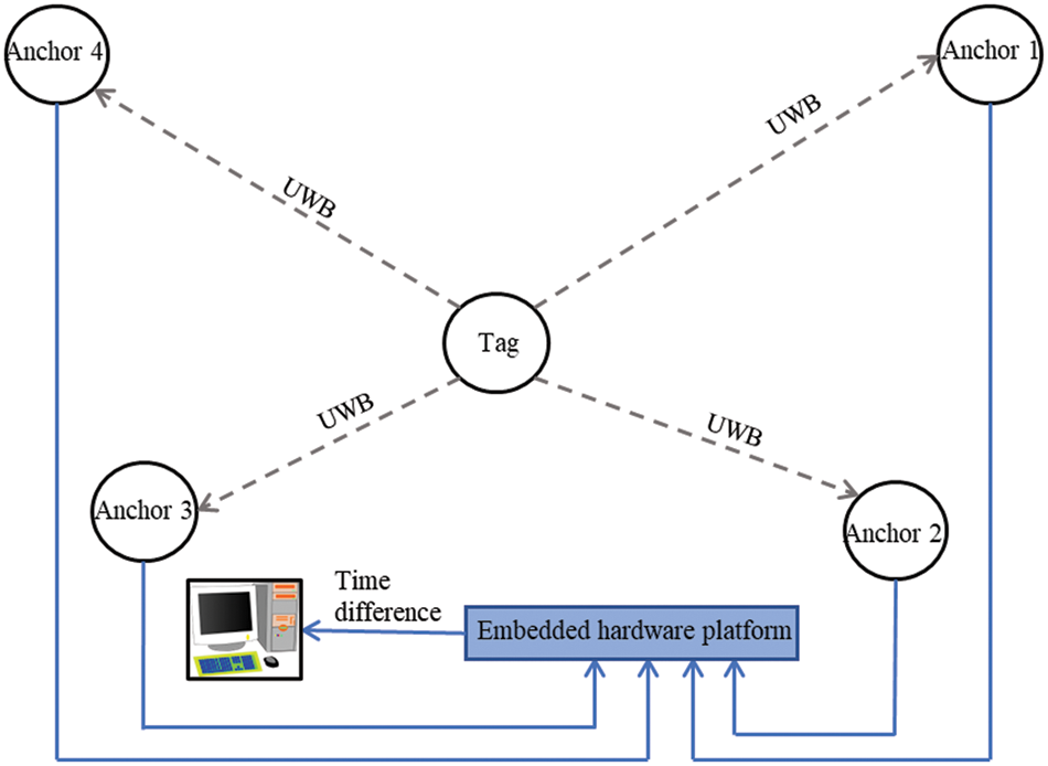
Figure 4: The TDOA localization based on the time differential
For a concise notation, we define the distance difference between an arbitrary target tag
where, the vector
where,
the error from the reference anchor error can be expressed as
where
Then, the conditional joint probability distribution function is
Thus, the Fisher Information Matrix (FIM) can be defined accordingly as
Because the variance of the unbiased position estimation of the lower bound of CRLB is not smaller than the inverse of the FIM, we have the following relations:
Then, we define a subfunction to simplify the FIM
FIM can be rewritten as
where
The CRLB of the location of the target tags in the 3-D UWB RTLS is
4 Experimental Studies and Results
To further verify the algorithm accuracy and engineering application reliability of the proposed 3-D UWB RTLS, we have built a three-dimensional experimental platform in the laboratory and strive to simulate the real application scene and environment as much as possible. The experimental platform was modeled as shown in Fig. 5, located in Qingdao, China, based on a previous fire outbreak that ruined the 7th floor of the building. Through collaborative efforts with the local fire department, possible solutions were generated. Lab C1503 is located at the University of Electronic Science and Technology administration building, Qingshuihe campus, Chengdu, China. The laboratory experiments were conducted in a controlled environment alongside a comparative experiment. This research aims to assess the feasibility and evaluate the performance of the 3-D UWB RTLS auto-positioning system on fire rescue. Since the auto-positioning itself brings error, the accuracy of the auto-positioning function is illustrated and assessed first. And then, the proposed WLS/TDOA algorithm is utilized to perform an estimation of the location of the target tags. At the same time, comparative experiments are conducted to compare the location estimation accuracy of the UWB RTLS system with auto-positioning under different environment settings.

Figure 5: Lab test experiment environment
The ATMD-GPX manufactured by Acam is the primary system utilized, and the time-to-digital converter (TDC) is set at 25 ps due to the limitation of the electron components. This benefits the strictly determined pulse propagation time through the logic gates in the TDC. The steps are as follows:
• The incoming signal triggers the time measurement.
• Rectangle pulse propagation through the logic gate with known propagation time.
• Hold measurement to receive incoming signal and read the number of logic gates the signal has passed through.
• Measure the time difference between the incoming signals.
The time difference is directly proportional to the number of logic gates that the pulse has traveled through between the start and stop events.
The 3-D experimental platform consists of three parts:
• A 10-story building model.
• Positioning calculation systems and reference anchors are distributed around the building and the base station.
• Mobile target tags are placed inside the building.
The building model used in this experimental platform is a multi-story structure modeled on a typical single high-rise city building. The building is made up of ten floors with a floor spacing of 0.20 m, and each floor is a 2.00 m square large flat floor. The transparent tempered glass material is equivalent to the actual building, and the reinforced concrete columns are simulated by thickened stainless steel. Various blocks of different sizes and materials are randomly placed on each floor as obstacles to test the penetrating ability of the signal.
The reference anchors distributed around the building consist of two parts, one is an air reference anchor deployed on the ceilings of the laboratory at the height of 2.85 m above the ground, and the other is three ground reference anchors located at the height of 0.50 m from the ground, as shown in Fig. 6. Note that the experimental area is measured with a high precision TS on ± (5 mm + 5 ppm) level to generate the actual locations for anchors and tags.
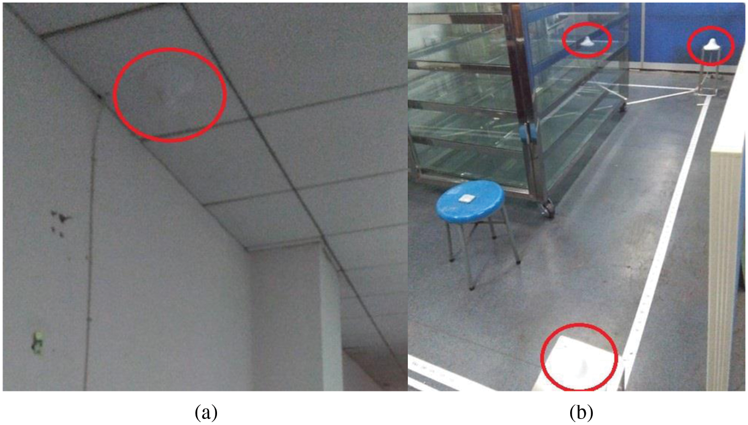
Figure 6: The reference anchors: (a) air reference anchor; (b) ground reference anchors
The accuracy of time differential measurement is essential for the overall system accuracy of TDOA-based RTLS. The computing complexity is minimized to the lower bond for the embedded hardware to directly compute the time differential of the arriving signals using the TDC. The TDC can measure the time elapsed between the appearance of two or more signals at its input ports and output the time difference.
4.1 Auto-Positioning Accuracy Assessment
The four anchors Anchor 1, Anchor 2, Anchor 3, and Anchor 4 (numbered clockwise as shown in Fig. 3), are configured and deployed at a fixed location in the experiment platform. The auto-positioning, as illustrated in Section 3.2, is performed 100 times to generate the locations of the four anchors. The TS experiment is also conducted 100 times under the same settings. The mean radial spherical error (MRSE) is used as the assessment metric to compare the accuracies of auto-positioning to the TS. Table 2 shows the statistical result of the accuracy comparison of auto-positioning and total station. Table 3 shows the average positioning error of auto-positioning of anchors at each coordinate separately. Note that the building model is temporarily moved outside the experiment region when conducting the comparative experiment to avoid NLOS impact on the locating accuracies. Concerning the mechanism of auto-positioning, it is worth emphasizing that the building model does not deteriorate its accuracy.


As can be inferred from Table 2, the average MRSE is 0.097 m for auto-positioning and 0.068 m for total station, which results in a difference of 0.029 m. With the auto-positioning mechanism and its simplicity, the location estimation accuracy is within 0.10 m for all the scenarios, as shown in Table 3. The results indicate that sub-meter-level accuracy is met and available for future application. Thus, the auto-positioning scheme is practical and suitable for sub-meter-level accuracy requirement use cases under the current settings.
4.2 The Location Estimation Accuracy Assessment
In this section, experiments are conducted to verify the algorithm accuracy and engineering application reliability of the proposed 3-D UWB RTLS in terms of the accuracy of the estimated target tags’ locations. This research presents and assesses five complex environments to model the fire rescue scene better. The five complex environments are based on the building model and are appended with extra obstacles generally seen in the fire scene.
• Basic building model: glass cabinet with base stainless steel metal frame (I)
• Basic building model with multiple wooden block obstacles (II)
• Basic building model with electronic devices at work (III)
• Basic building model with multiple stationary impenetrable objects (IV)
• Basic building model with multiple moving impenetrable objects (V)
To validate the location estimation accuracy of the system, we place the target tag at four known typical locations with actual coordinates

From the results in Table 4 above, it can be inferred that different environmental settings influence positioning accuracy to different degrees. The location estimation accuracy in the worst scenario is within 0.20 m, which equals the floor spacing setting of our platform.
As can be inferred from Table 4, as the position of the target point becomes high, the value of the z-axis increases, and the error increases. The reason behind this phenomenon is that there is only one air reference anchor. Since the obstacles introduced are impenetrable to electromagnetic waves in environments IV and V, their locating accuracy is further impacted. In environment V, the occlusion probability is reduced because of the moving properties of impenetrable obstacles, which has a certain effect on reducing the error, but the effect is not significant.
Although the values on the z-axis have relatively large errors, only floor information is needed in application practice. Thus, the accuracy of the RTLS is furtherly improved. Therefore, it can be concluded that the proposed UWB RTLS auto-positioning system can reach 0.20 m accuracy, which is supreme to other similar positioning systems listed in Table 1. And since the CRLB of the proposed locating algorithm is 0.05, which is just a quarter of our accuracy. The reason for comparing the estimation accuracy with CRLB is that we cannot find a similar comparative 3-D RTLS which can penetrate the walls to provide locating service in the literature. The comparison also demonstrates that there still exists room for upgrading our system, and the major task of future research is enhancing the auto-positioning accuracy.
The performance of the estimator is assessed by the lower bound on the MRSE estimation error. Based on the proposed lower error bound of 0.05 m [34–37], the MRSE achieved based on the proposed method, auto-positioning and the total station were both greater than 0.05 m. The results of the auto-positioning based on the proposed algorithm were compared with the results of the total station. The proposed algorithm performed well based on the accuracy and difference of the MRSE.
To compare the system performance with current existing similar systems present in the literature review section, the 3D-UWB-RTLS proposed in this research work made significant progress in accuracy to reaching a compelling 0.20 m, adding that the competing innovation proposal of auto-positioning is also a contribution to the field of discipline. Though this research work initially aims to tackle the problem of fire rescue, the scope of application is not limited to it; the system can further benefit the construction site, intelligent manufacturing, etc. And the limitation of the system is straightforward when it requires precise locating while the accuracy is limited, which calls for innovation either on algorithms or hardware or both.
As a unique upgrade to 3D-UWB-RTLS based on TDOA for application practice, the auto-positioning scheme was proposed and validated in this research work. With the auto-positioning function to generate the locations of four anchors and set up the measuring coordinates, the hassle of measuring with extra measurement instruments like the total station is eliminated. The comparative experiment demonstrates that the auto-positioning scheme is practical and suitable for sub-meter-level accuracy requirement use cases. The experiment proves that the 3D-UWB-RTLS with auto-positioning has high stability and positioning accuracy. The CRLB value of the proposed positioning algorithm is obtained, which is supreme to other algorithms in the literature. And the anchor location estimation accuracy is within 0.20 m in the worst scenario. A WLS/TDOA locating algorithm is proposed to improve the location estimation accuracy of the target tags, together with the derivation of its CRLB. The statistical summary of the results shows the proposed UWB RTLS auto-positioning system can reach 0.20 m accuracy for target tag tracking, which is approximate to the algorithm’s CRLB (0.05 m). This research work facilitates the simple and quick installation of the UWB RTLS to deploy with the standard fire rescue procedure simultaneously; even though the auto-positioning scheme almost doubled the MRSE of the anchor location estimation, it provides a helpful direction for launching the UWB RTLS in application practice. Adding more air anchors cloud helps with increasing the estimation accuracies on the Z coordinate. Nonetheless, the location estimation accuracy for target tracking still reached a relatively high 0.20 m value compared to similar tracking systems listed in Table 1 (UWB 0.30 m). At the very beginning of system design, computing complexity was shifted to the lower bond, making the embedded hardware directly compute the time differential of the arriving signals for TDOA information. Future works would look at designing the system to solve the problem of dense target-setting scenarios.
Funding Statement: The authors received no specific funding for this study.
Conflicts of Interest: The authors declare that they have no conflicts of interest to report regarding the present study.
References
1. S. H. Jo, J. Woo, S. Y. Kim and J. H. Jeong, “Development of positioning technology using led,” IEEE Photonics Journal, vol. 15, no. 1, pp. 1–7, 2023. [Google Scholar]
2. R. P. Barnwal, P. Roy and P. K. Pal, “Experimental evaluation of indoor localization methods for industrial IoT environment,” Journal of Scientific and Industrial Research, vol. 81, no. 3, pp. 294–307, 2022. [Google Scholar]
3. F. Zafari, A. Gkelias and K. K. Leung, “A survey of indoor localization systems and technologies,” IEEE Communications Surveys & Tutorials, vol. 21, no. 3, pp. 2568–2599, 2019. [Google Scholar]
4. Y. Huang, A. Hammad and Z. Zhu, “Providing proximity alerts to workers on construction sites using bluetooth low energy RTLS,” Automation in Construction, vol. 132, pp. 103928, 2021. [Google Scholar]
5. M. H. A. Ansaripour, K. Kim, O. Gnawali and H. Oyediran, “ViPER+: Vehicle pose estimation using ultra-wideband radios for automated construction safety monitoring,” Applied Sciences, vol. 13, no. 3, pp. 1581, 2023. [Google Scholar]
6. A. K. Sohi and A. Kaur, “A novel modified Kock-Snowflake fractal MIMO antenna for 4G/5G UWB communication gadgets,” Microwave and Optical Technology Letters, vol. 65, no. 1, pp. 311–319, 2023. [Google Scholar]
7. B. Cao, S. Wang, S. Ge, F. Chen and H. Zhang, “UWB anchor node optimization deployment using MGWO for the coal mine working face end,” IEEE Transactions on Instrumentation and Measurement, vol. 72, pp. 1–12, 2023. [Google Scholar]
8. M. Elsanhoury, P. Mäkelä, J. Koljonen, P. Välisuo, A. Shamsuzzoha et al., “Precision positioning for smart logistics using ultra-wideband technology-based indoor navigation: A review,” IEEE Access, vol. 10, pp. 44413–44445, 2022. [Google Scholar]
9. C. Zhang, A. Hammad and S. Rodriguez, “Crane pose estimation using UWB real-time location system,” Journal of Computing in Civil Engineering, vol. 26, no. 5, pp. 625–637, 2012. [Google Scholar]
10. M. J. Skibniewski and W. S. Jang, “Simulation of accuracy performance for wireless sensor-based construction asset tracking,” Computer-Aided Civil and Infrastructure Engineering, vol. 24, no. 5, pp. 335–345, 2009. [Google Scholar]
11. M. W. Park and I. Brilakis, “Construction worker detection in video frames for initializing vision trackers,” Automation in Construction, vol. 28, pp. 15–25, 2012. [Google Scholar]
12. W. S. Jang and M. J. Skibniewski, “Embedded system for construction asset tracking combining radio and ultrasound signals,” Journal of Computing in Civil Engineering, vol. 23, no. 4, pp. 221–229, 2009. [Google Scholar]
13. N. Pradhananga and J. Teizer, “Automatic spatio-temporal analysis of construction site equipment operations using GPS data,” Automation in Construction, vol. 29, pp. 107–122, 2013. [Google Scholar]
14. S. Thiede, P. Ghafoorpoor, B. P. Sullivan, S. Bienia, M. Demes et al., “Potentials and technical implications of tag based and AI enabled optical real-time location systems (RTLS) for manufacturing use cases,” CIRP Annals, vol. 71, no. 1, pp. 401–404, 2022. [Google Scholar]
15. S. Huang, Y. Guo, S. Zha, F. Wang and W. Fang, “A real-time location system based on RFID and UWB for digital manufacturing workshop,” Procedia CIRP, vol. 63, pp. 132–137, 2017. [Google Scholar]
16. K. M. Rashid, J. Louis and K. K. Fiawoyife, “Wireless electric appliance control for smart buildings using indoor location tracking and BIM-based virtual environments,” Automation in Construction, vol. 101, pp. 48–58, 2019. [Google Scholar]
17. X. Yuan, Y. Bi, M. Hao, Q. Ji, Z. Liu et al., “Research on location estimation for coal tunnel vehicle based on ultra-wide band equipment,” Energies, vol. 15, no. 22, pp. 8524, 2022. [Google Scholar]
18. Y. Wang, S. Yang, F. Li, Y. Wu and Y. Wang, “FallViewer: A fine-grained indoor fall detection system with ubiquitous Wi-Fi devices,” IEEE Internet of Things Journal, vol. 8, no. 15, pp. 12455–12466, 2021. [Google Scholar]
19. S. Kumar, S. Gil, D. Katabi and D. Rus, “Accurate indoor localization with zero start-up cost,” in Proc. of the 20th Annual Int. Conf. on Mobile Computing and Networking, Maui, Hawaii, USA, pp. 483–494, 2014. [Google Scholar]
20. K. Sugapriya and S. Omkumar, “Textile UWB 5G antenna for human blood clot measurement,” Intelligent Automation and Soft Computing, vol. 36, no. 1, pp. 803–818, 2023. [Google Scholar]
21. Z. Yang, Z. Zhou and Y. Liu, “From RSSI to CSI: Indoor localization via channel response,” ACM Computing Surveys (CSUR), vol. 46, no. 2, pp. 1–32, 2013. [Google Scholar]
22. A. Giretti, A. Carbonari, B. Naticchia and M. DeGrassi, “Design and first development of an automated real-time safety management system for construction sites,” Journal of Civil Engineering and Management, vol. 15, no. 4, pp. 325–336, 2009. [Google Scholar]
23. H. M. Khoury and V. R. Kamat, “Evaluation of position tracking technologies for user localization in indoor construction environments,” Automation in Construction, vol. 18, no. 4, pp. 444–457, 2009. [Google Scholar]
24. T. Cheng, M. Venugopal, J. Teizer and P. Vela, “Performance evaluation of ultra wideband technology for construction resource location tracking in harsh environments,” Automation in Construction, vol. 20, no. 8, pp. 1173–1184, 2011. [Google Scholar]
25. Y. K. Cho, J. H. Youn and D. Martinez, “Error modeling for an untethered ultra-wideband system for construction indoor asset tracking,” Automation in Construction, vol. 19, no. 1, pp. 43–54, 2010. [Google Scholar]
26. A. Carbonari, A. Giretti and B. Naticchia, “A proactive system for real-time safety management in construction sites,” Automation in Construction, vol. 20, no. 6, pp. 686–698, 2011. [Google Scholar]
27. J. H. Durant, L. Wilkins, K. Butler and J. F. Cooper, “Determining the maximum information gain and optimizing experimental design in neutron reflectometry using the Fisher information,” Journal of Applied Crystallography, vol. 54, no. 4, pp. 1100–1110, 2021 [Google Scholar] [PubMed]
28. T. Bodrumlu and F. Caliskan, “Indoor position estimation using ultrasonic beacon sensors and extended kalman filter,” Engineering Proceedings, vol. 27, no. 1, pp. 16, 2022. [Google Scholar]
29. B. Lee, D. M. Woo, M. K. Park and S. Kim, “Development of self-localizer using collaboration of trilateration and triangulation,” in 2014 11th Int. Conf. on Fuzzy Systems and Knowledge Discovery (FSKD), Xiamen, China, IEEE, pp. 729–733, 2014. [Google Scholar]
30. F. Jamil, N. Iqbal, S. Ahmad and D. H. Kim, “Toward accurate position estimation using learning to prediction algorithm in indoor navigation,” Sensors, vol. 20, no. 16, pp. 4410, 2020 [Google Scholar] [PubMed]
31. G. A. da Cunha, F. V. Lopes and T. da Rocha Honorato, “Influence of traveling wave detection sensitivity on transient pattern recognition-based single-ended fault location approach,” in 2019 Workshop on Communication Networks and Power Systems (WCNPS), IEEE, pp. 1–5, 2019. [Google Scholar]
32. Y. Liu, Y. Jiao and H. Ma, “Joint 2-D angle estimation using TDOA in distributed multi-antenna system,” in 2020 IEEE Int. Conf. on Power, Intelligent Computing and Systems (ICPICS), Shenyang, China, IEEE, pp. 642–650, 2020. [Google Scholar]
33. K. W. Cheung, H. C. So, W. K. Ma and Y. T. Chan, “Least squares algorithms for time-of-arrival-based mobile location,” IEEE Transactions on Signal Processing, vol. 52, no. 4, pp. 1121–1130, 2004. [Google Scholar]
34. T. H. Nguyen and L. Xie, “Relative transformation estimation based on fusion of odometry and UWB ranging data,” arXiv preprint arXiv: 2202.00279, 2022. [Google Scholar]
35. J. A. Del Peral-Rosado, P. Nolle, S. M. Razavi, G. Lindmark, D. Shrestha et al., “Design considerations of dedicated and aerial 5G networks for enhanced positioning services,” in 2022 10th Workshop on Satellite Navigation Technology (NAVITEC), Noordwijk, Netherlands, IEEE, pp. 1–12, 2022. [Google Scholar]
36. L. Qiu, W. Qu, H. Pang and J. Yang, “G-CRLB analysis for target localization in through-the-wall radar,” in 2019 IEEE Int. Conf. on Signal Processing, Communications and Computing (ICSPCC), Dalian, China, IEEE, pp. 1–4, 2019. [Google Scholar]
37. M. Gao, X. Qiu, Y. Cheng, J. Lv and C. Ding, “A robust track error estimation method for airborne SAR based on accuracy analysis model,” Remote Sensing, vol. 14, no. 22, pp. 5769, 2022. [Google Scholar]
Cite This Article
 Copyright © 2023 The Author(s). Published by Tech Science Press.
This work is licensed under a Creative Commons Attribution 4.0 International License , which permits unrestricted use, distribution, and reproduction in any medium, provided the original work is properly cited.
 Downloads
 Citation Tools