
 Submit a Paper
 Propose a Special lssue
 Open Access
ARTICLE
Tailoring Tribological Behavior of PMMA Using Multi-Component Nanofillers: Insights into Friction, Wear, and Third-Body Flow Dynamics
1 Department of Mechanical Engineering, National Cheng Kung University, Tainan, 70101, Taiwan
2 Department of Mechanical Engineering, Universitas Negeri Padang, Padang, 25173, Sumatera Barat, Indonesia
* Corresponding Author: Shih-Chen Shi. Email:
Journal of Polymer Materials 2025, 42(4), 1075-1095. https://doi.org/10.32604/jpm.2025.072263
Received 22 August 2025; Accepted 23 October 2025; Issue published 26 December 2025
 View Full Text
 Download PDF
Abstract
Polymethyl methacrylate (PMMA) is widely used in diverse applications such as protective components (e.g., automotive lamp covers and structural casings), optical devices, and biomedical products, owing to its lightweight nature and impact resistance. However, its surface hardness and wear resistance remain insufficient under prolonged exposure to abrasive environments. In this study, a multi-filler strategy with nano-silica (SiO2), brominated lignin (Br-Lignin), and cellulose nanocrystals (CNCs) was employed to enhance PMMA tribological properties. SiO2 provided localized reinforcement, Br-Lignin established stable network structures, and CNCs improved compactness, enabling strong synergistic effects. As a result, the composites achieved up to 20% higher hardness, a 38% lower friction coefficient, and a 78% reduction in wear rate. Beyond performance metrics, this work advances prior PMMA reinforcement studies by (i) applying third-body flow theory and velocity accommodation mechanisms (VAM) to systematically interpret wear-track morphology and dynamic lubrication processes. These contributions highlight not only the effectiveness of multi-filler design in tailoring tribological behavior but also establish a tribology-driven framework for developing next-generation PMMA composites for durable protective casings and related high-wear applications.Keywords
Over the last few decades, polymer, metal, and ceramic have been the primary material options considered for structural and functional applications [1–3]. Each material offers distinct advantages; for example, polymers not only provide effective damping against impact loads from unexpected activities but also find broad use in other sectors.
Composite materials have evolved from ancient straw-reinforced bricks to modern fiber- and particle-reinforced polymers developed in the mid-20th century. Since the 1960s, fiber-reinforced polymers have achieved strength-to-weight ratios up to 5–7 times higher than steel, which drove their adoption in aerospace and automotive sectors.
Fillers have been central in enhancing the mechanical, thermal, and tribological performance of polymers [4–6]. Micro-scale reinforcements such as glass fibers and ceramic particulates improved hardness and wear resistance by 30%–50%, while recent advances using nano-reinforcements like graphene oxide, silica, and natural fibers have reported wear rate reductions of up to 70% [7–9].
Polymethyl methacrylate (PMMA) is widely used in automotive lamp covers, lightboxes, and structural housings due to its excellent optical clarity, lightweight nature, and impact resistance [10]. However, its relatively low surface hardness and wear resistance make it vulnerable to abrasion, sand erosion, and mechanical failure under prolonged use. Improving the surface durability of PMMA is thus essential for extending its lifespan and enabling advanced applications such as protective covers and precision enclosures.
The global market for PMMA reached $6.4 billion in 2024 and is projected to grow to $8.9 billion by 2030, with a compound annual growth rate (CAGR) of 5.5% [11]. This demand underscores the need to address PMMA’s mechanical limitations. Developing effective reinforcement strategies is crucial to meet performance expectations in emerging industrial applications [12,13].
Filler reinforcement has been recognized as one of the most effective approaches to enhance the mechanical properties of PMMA. Several studies have investigated how inorganic and organic fillers can improve the microstructure and interfacial interactions of the composite [14,15]. Multifilter systems have gained attention because single fillers have often failed to deliver balanced improvements across multiple properties [16,17].
This study investigates a hybrid filler approach using SiO2, Br-Lignin, and cellulose nanocrystals (CNCs) to reinforce PMMA. SiO2 and CNCs provide rigidity and stress transfer capability [18,19], while Br-Lignin contributes a stable 3D network structure [20]. These fillers are expected to work synergistically to improve the composite’s abrasion resistance and structural integrity. Although previous studies have explored binary filler systems in PMMA [21,22], little research has systematically evaluated the influence of hybrid filler ratios.
Recent research has increasingly emphasized hybrid inorganic–bio-based nanofillers as a means to overcome the limitations of single and binary systems. Studies show that binary PMMA composites often suffer from two main issues: (i) poor dispersion of lignin, which tends to self-assemble into aggregates and weakens the matrix, and (ii) inadequate interfacial bonding between rigid inorganic particles like SiO2 and flexible bio-based reinforcements such as CNCs, which creates stress concentrations and accelerates delamination [23].
Reports on lignin-derived functional composites confirm that compatibilization or grafting strategies are essential to stabilize dispersion and maintain mechanical integrity, while investigations of silica–cellulose hybrids demonstrate that surface chemistry tuning significantly enhances lubrication stability and wear suppression [24].
Furthermore, very recent reviews highlight that only multi-component systems, where fillers share complementary roles, can simultaneously provide hardness, toughness, and stable tribological films under sliding. These findings suggest that a ternary approach, combining SiO2 for localized reinforcement, Br-Lignin for network stability, and CNCs for compactness and crack resistance, can directly address the weaknesses that constrain binary systems.
The novelty of this work lies in the application of a tribology-driven design approach, which integrates third-body flow theory and velocity accommodation mechanisms to elucidate how hybrid nanofillers modulate wear behavior and friction stabilization. Through systematic evaluation of wear track morphology, friction coefficient trends, and wear rate data, this study provides new insights into the role of hybrid nanofillers in governing surface transformation and lubrication mechanisms under dynamic contact.
The proposed approach enables the tailoring of tribological behavior in PMMA composites, offering a new pathway for developing high-durability polymer materials suitable for protective applications in harsh or abrasive environments.
Lignin (Indulin AT) is purchased from Taimax, (New Taipei, Taiwan), and tetrahydrofuran (THF) from Avantor, (Radnor, PA, USA). Other reagents include α-bromoisobutyryl bromide (BiBB, Sigma-Aldrich, St. Louis, MO, USA), argon gas (Yun Hai Gas Co., Tainan, Taiwan), and deionized (DI) water (Yean Hern Chemical, Kaohsiung, Taiwan). Additional materials include tetraethoxysilane (TEOS, 98%, Thermo Scientific, Waltham, MA, USA), ethanol (99.5%, Shin Shin Chemical, Tainan, Taiwan), ammonium hydroxide (25%, PanReac AppliChem, Darmstadt, Germany), PMMA (Sigma-Aldrich), lab-made Br-Lignin and SiO2 suspension, cellulose nanocrystals (CNCs, CellForce, Canada), MPTS (Sigma-Aldrich, St. Louis, MO, USA), benzoyl peroxide (BPO, Sigma-Aldrich, St. Louis, MO, USA), copper wire, CuBr2 (99%, Alfa Aesar, Ward Hill, MA, USA), 2,2′-bipyridine (BPY, igma-Aldrich, St. Louis, MO, USA), and hydrochloric acid (Shin Shin Chemical, Tainan, Taiwan).
2.2 Brominated Lignin (Br-Lignin) Synthesis
Lignin is dissolved in THF at a ratio of 1 g:50 mL using ultrasonic treatment (20 kHz, 1200 W, pulsed 5 s on/3 s off, 50% power, 20 min). The solution is transferred to a four-neck flask, vacuumed until bubbling appears, and purged with argon three times to ensure an inert atmosphere. BiBB is added at 1 g:0.5 mL, and the mixture is stirred at 45°C for 48 h. This step is followed by precipitation with DI water and washing, after which the final product is dried for 24 h to obtain Br-Lignin.
2.3 Nano SiO2 Suspension Preparation
Nano-SiO2 is synthesized via a sol-gel method by mixing TEOS and ethanol, which is then stirred at 70°C and 200 rpm for 10 min. DI water is added at 0.50 ± 0.05 mL min−¹ and reacted for an additional 10 min. Aqueous ammonia (25 wt%) is then fed via syringe pump at 0.20 ± 0.02 mL min−¹ while increasing stirring to 600 rpm, followed by 30 min of hydrolysis/condensation at 70°C. The volume ratio of precursors per gram of SiO2 is TEOS:C2H5OH:DI water:NH3 = 3.696:1.944:1.199:0.00512 (mL), corresponding to a molar ratio of 1:2:4:0.0164 (mol).
2.4 PMMA-Based Composite Preparation
The following steps were used to prepare. PMMA/SiO2 Composite. PMMA is dissolved in THF (1 g:5 mL) at 60°C and 300 rpm and then reacted with BPO (1:0.01 g) for at least 5 h. SiO2 suspension prepared from Section 2.3 is added to the PMMA solution and stirred for 1 h. MPTS is added (1 g:4.73 mL; molar ratio 2:1), followed by a 2–4 h grafting reaction at 70°C. The mixture is then poured into Teflon molds, sealed, vented, and dried at 60°C for 2 days. The following steps were used to prepare. PMMA/SiO2/Br-Lignin Composite. PMMA and 4/5 of THF are mixed with BPO to activate the polymer, while Br-Lignin is dissolved in the remaining THF using ultrasonication for 20 min. The Br-Lignin solution is combined with the activated PMMA, and a catalyst mixture (CuBr2:BPY = 0.1:0.01 g) is prepared in a second beaker. After vacuum-argon cycling, the catalyst and acid-washed copper wire are added to initiate ATRP at room temperature for 24 h; MPTS and SiO2 suspension are subsequently added and reacted at 70°C, then cast and dried as described.
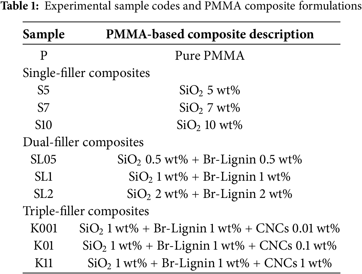
The following steps prepare PMMA/SiO2/Br-Lignin/CNCs Composite. This process follows the PMMA/SiO2/Br-Lignin method with one modification. After the 30-min NH3 stir step in Section 2.3, CNCs are added in a defined ratio and ultrasonicated for 10 min, a duration selected based on reported optimum conditions in the literature [25]. The mixture is then stirred for 2 h to form the CNCs/SiO2 hybrid suspension. Table 1 shows the formulation and code for all samples.
2.5 Mechanical and Tribological Testing
Composite materials are crushed and dried at 70°C for at least 4 h to remove residual moisture and solvent. Two grams of powder are filled into a stainless-steel mold (30 mm × 30 mm × 3 mm), which reaches 80% of the mold volume. Using a hot press, the sample is preheated and pressed in stages: from 0.5 to 2 to 10 MPa. Final curing is performed at 185°C for 20 min, followed by cooling to 80°C under pressure before demolding.
Microhardness is measured using a Micro Vickers Hardness Tester (Shimadzu) with a loading rate of 0.1 N/s and a dwell time of 10 s. Five random indentations are performed on each sample, and the average value is used to evaluate surface hardness. Wear performance is tested using a ball-on-disk tribometer (POD-FM800-25NT, Freeform P.M. Co.) under the following conditions: a 6.35 mm SUJ-2 steel ball, a 10 mm wear track, 318 rpm, a 0.35 kg load, and sliding distances of 50, 100, and 150 m. All tests were conducted under standard laboratory conditions (approximately 25 ± 2°C, 60 ± 5% RH). A 3D Laser Scanning Microscope (VK-9500, Keyence) is used to scan the wear tracks and generate 3D profile data. Cross-sectional profiles are extracted using VK Analyzer by selecting a linear segment defined by the rough valleys and scar bottom. The wear area is calculated from this section and multiplied by the wear path length to obtain the total wear volume.
3.1 Multicomponent Filler Composites
FTIR spectroscopy investigates the grafting behavior of PMMA-based composites containing SiO2, Br-Lignin, and CNCs. Fig. 1a shows the characteristic absorption bands of pure PMMA at 1140 cm−1 (C–O stretching of –COOCH3) and 1720 cm−1 (C=O stretching) [26], while Fig. 1b reveals a peak at 970 cm−1 attributed to Si–OH stretching of SiO2. A distinct band at 1053 cm−1 corresponding to Si–O–Si asymmetric stretching further confirms the successful grafting between PMMA and SiO2. Fig. 1c exhibits Br-Lignin peaks at 1140 cm−1 (C–O) and 1720 cm−1 (C=O) and SiO2-related peaks at 970 and 1053 cm−1. These simultaneous signals validate that Br-Lignin and SiO2 have been grafted onto the PMMA backbone [27]. In Fig. 1d, the K01 sample exhibits the same set of peaks for SiO2 (970, 1053 cm−1) and Br-Lignin (1140, 1720 cm−1), indicating successful multi-filler grafting. The presence of CNCs does not affect the FTIR spectrum.
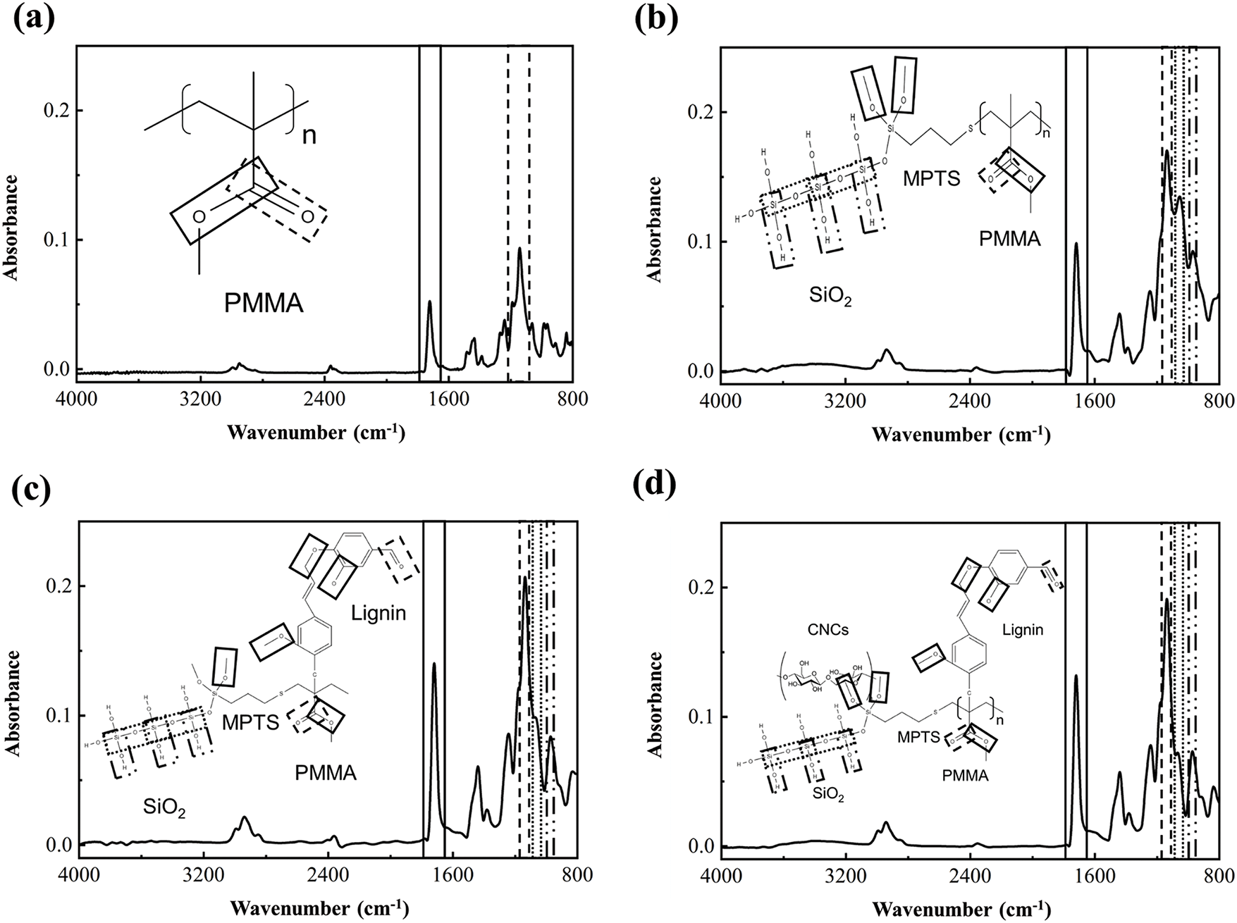
Figure 1: FTIR spectra of pure PMMA and its composites: (a) pure PMMA, (b) PMMA/SiO2, (c) PMMA/SiO2/Br-Lignin, (d) PMMA/SiO2/Br-Lignin/CNCs
3.1.1 Hardness Analysis of Hybrid Filler Composites
Fig. 2 shows the hardness variation of pure PMMA (P) and its composites with various filler combinations at three different concentrations. The PMMA/SiO2 series (S5, S7, S10) formed reinforced regions within the PMMA matrix, increasing the hardness [28]. However, as the SiO2 content increased, the improvement in hardness gradually diminished, suggesting that the reinforcing effect may saturate or even induce embrittlement beyond a certain threshold [29]. The ternary filler system (K001, K01, K11) consistently exhibited a stable trend of hardness enhancement across different compositions. This behavior implies a synergistic effect among the multiple fillers, contributing to improved structural compactness and mechanical reinforcement. Overall, the triple-filler composites demonstrated superior performance compared to the other groups. In contrast, the PMMA/SiO2/Br-Lignin system (SL05, SL1, SL2) showed relatively low hardness values. This phenomonen may be attributed to the nature of lignin as a biopolymer, which tends to aggregate during dispersion [30]. Such aggregation could inhibit uniform filler distribution and compromise the structural integrity of the matrix, leading to an overall reduction in hardness [31].

Figure 2: Surface hardness of pure PMMA and composites with different fillers and concentrations
3.1.2 Analysis of Tribological Properties of Hybrid Filler Composites
Analysis of Average Friction Coefficient
The three-body tribological theory consists of two key concepts: the Velocity Accommodation Mechanism (VAM) and Third Body Flow [32,33]. The “+” grading system was defined as a semi-quantitative scale based on wear track morphology and debris distribution observed by the 3D laser scanning microscopy. In this classification, “+” denotes weak or incipient third-body activity, characterized by localized or discontinuous debris traces; “++” indicates moderate activity, with partial coverage and visible recirculation of debris along the wear scar; and “+++” represents strong or stable activity, where continuous debris layers form lubricating films that cover large portions of the contact zone.
The VAM describes how the third body modifies its position and motion—“Sites” and “Modes”—within the tribological interface, thus influencing friction and wear behavior. This dynamic adaptation determines energy dissipation and the stability of the sliding contact. The tribological interface includes four structural layers: S1 represents the counterface and its supporting substrate. S2 is the interfacial transformation layer between S1 and S3, often formed through frictional reactions or structural transitions, also known as the structural tribological transformation (STT) layer, with thicknesses ranging from nanometers to tens of micrometers [33].
S3 refers to debris or externally applied particles (i.e., the actual third body), while S4 represents the material’s surface layer. Velocity accommodation occurs via four distinct modes depending on the third body’s mechanical response: M1 (Elastic), M2 (Rupture), M3 (Shearing/Sliding), and M4 (Rolling). These deformation modes are driven by applied loads and motion, controlling how the third body contributes to lubrication and the dissipation of frictional energy [33]. For example, M1 aids in load buffering, M3 facilitates stable sliding, and M4 enables low-friction rolling when granular lubricants are present.
Regarding third-body flow, four types are classified based on the movement within or around the contact zone. Internal Flow (Qi) circulates within the interface, sustaining lubrication, while External Flow (Qe) exits the zone permanently. Recirculated Flow (Qr) re-enters after temporary ejection, and Wear Flow (Qw) refers to material fully expelled from the contact and no longer active in lubrication [33].
This framework enables the present study to investigate how various lubrication conditions impact third-body migration and retention. By mapping the presence of these flows using a “+” sign system, we systematically assess their impact on interface friction behavior. The analysis aims to clarify the mechanical contributions of third-body dynamics under various material and surface conditions.
Fig. 3 presents the average friction coefficient of the PMMA/SiO2 composite under different sliding distances. This section interprets the variation trends by integrating wear morphology (Fig. 4) and third-body mechanism schematics. As shown in Fig. 4a, at 50 m, the material surface initially underwent shear sliding (S4M3), generating rough, angular wear debris. These irregular particles participated in wear through shear-sliding (S3M3), resulting in plowing and groove formation (S4M3). At this stage, the third-body particles primarily acted as early-stage external (Qe) and internal flows (Qi), without forming a stable lubricating layer. Consequently, the friction coefficient remained relatively high.

Figure 3: Average friction coefficient of the composite at different sliding distances
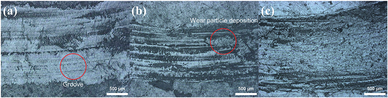
Figure 4: Wear track morphology of S5 at (a) 50 m, (b) 100 m, and (c) 150 m
As the distance increased to 100 m (Fig. 4b), some surface material appeared to be removed with the debris, forming wide, directional scars typical of adhesive wear (S1M3). The debris experienced continued shear-sliding (S3M3) within the contact interface, and initial signs of lubricating layer formation (S2M3) were observed. Stable Qi and partial fusion of debris into a recirculating layer (Qr) emerged, resulting in a more stable lubricating condition and a reduced friction coefficient compared to 50 m.
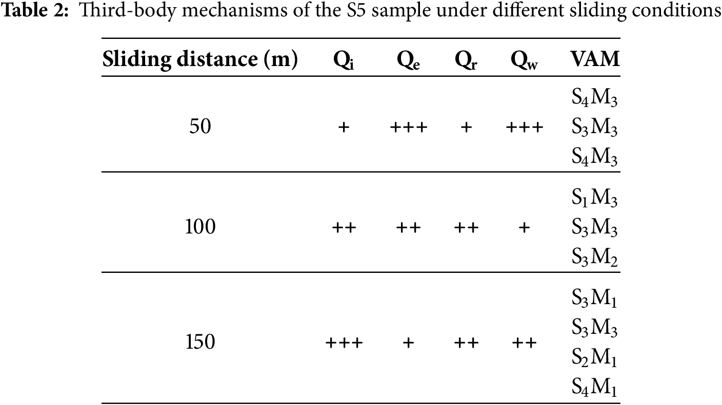
At 150 m (Fig. 4c), a stable lubricating layer (S2) formed between the counterface and third-body debris (S1 and S3). Particles underwent shear, adhesion, and restructuring (S3M2, S3M3), creating a continuous lubricating film across the surface. Wear marks became uniform, covering the entire contact zone; plowing and adhesion marks were significantly reduced (S4M1), indicating effective load transfer and energy dissipation through the lubricating layer (S2M1), with Qi dominating and Qr maintaining localized flow continuity. Table 2 summarizes the adaptive behavior modes and third-body flow mechanisms of the S5 sample across various sliding speeds, facilitating a clearer understanding of its dynamic tribological evolution.
At 50 m (Fig. 5a), the S7 sample primarily exhibited adhesive wear (S1M3), resulting in distinct shear deformation and material detachment at the contact surface. Third-body particles formed during sliding accumulated along the contact zone edge (S3M2), and some entered the interface to undergo shear-driven rearrangement (S3M3), indicating initial lubrication behavior. This phenomenon is interpreted as localized Qi, which provides buffering under contact pressure and helps suppress further increases in friction.
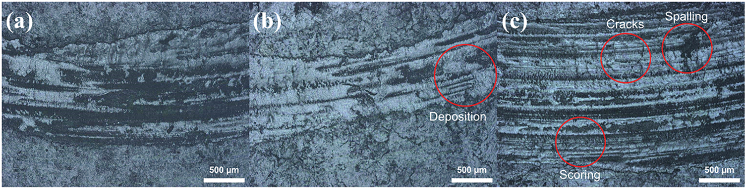
Figure 5: Wear track morphology of S7 at (a) 50 m, (b) 100 m, and (c) 150 m
At 100 m (Fig. 5b), the dominant wear mechanisms included plowing (S4M3) and adhesive wear (S1M3). Grooves produced by plowing lacked significant material accumulation on their sides, suggesting they may have developed during the later stages of wear. Third-body particles continuously accumulate at this stage and are redistributed along the edges, forming an unstable sliding layer (S3M2) and exhibiting early Qr behavior. This improvement contributes to partial interface stabilization and explains the reduced friction compared to 50 m.
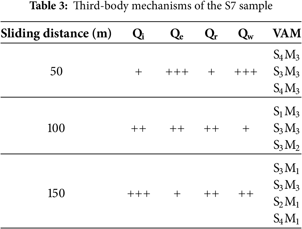
At 150 m (Fig. 5c), clear scratch marks and microcracks were observed on the worn surface. In addition to sustained plowing and adhesive wear (S4M3, S1M3), repeated stresses from extended sliding led to local fatigue and crack initiation (S4M2), deteriorating surface integrity. Third-body debris underwent repeated shearing and fusion (S3M2), forming unstable sliding paths. At the same time, some particles were expelled (Qe), indicating the failure of Qi and Qr, which weakened lubrication and increased friction. Table 3 summarizes the adaptive behavior modes and transitions in third-body flow observed in the S7 sample at various sliding speeds, helping clarify the evolution of its dynamic wear behavior.
As shown in Fig. 6, increasing the SiO2 content to 10 wt% significantly increased hardness and brittleness, making plastic deformation at the surface more difficult (S4M1). However, the hard particles also promoted stress concentration, causing the brittle surface to undergo cracking and delamination due to fracture propagation (S4M2), weakening the material’s structural integrity. Regarding third-body flow, the lack of plastic deformability prevented the formation and renewal of a stable sliding lubricating layer, resulting in underdeveloped or ineffective Qi and Qr. Due to the absence of visible wear scars, rigid particles were more likely to be expelled directly from the interface, indicating dominant Qe behavior. The accumulation of fractures and delamination caused by increased brittleness and lubrication failure led to friction coefficients exceeding the upper measurement limit at 100 m and 150 m. As a result, the wear tests at these distances were prematurely terminated. Table 4 summarizes the adaptive behavior modes and third-body flow mechanisms observed in the S10 sample under various sliding conditions, helping elucidate its dynamic wear evolution.
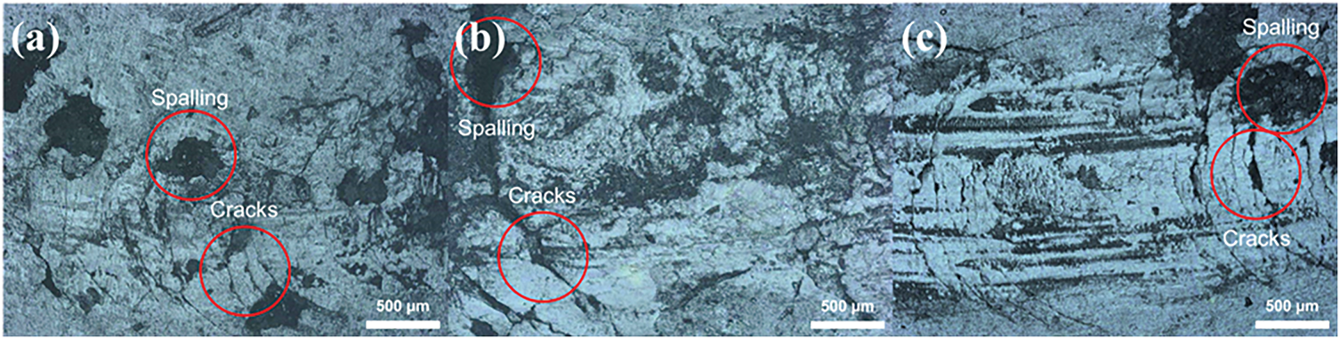
Figure 6: Wear track morphology of S10 at (a) 50 m, (b) 100 m, and (c) 150 m
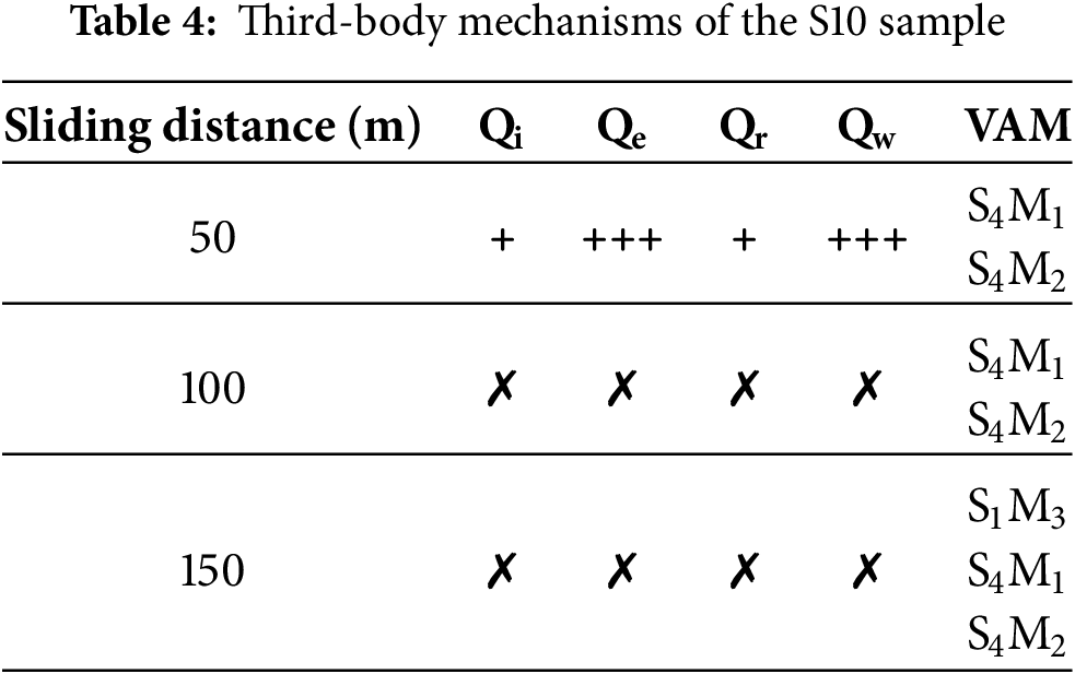
Fig. 7 presents the average friction coefficient of the PMMA/SiO2/Br-Lignin composite under different sliding distances. Figs. 8–10 provide surface morphology evidence at different sliding distances. As shown in Fig. 8, at 50 m, the wear tracks appeared relatively smooth, and the dominant wear mode was adhesive wear (S1M3), resulting in only mild surface damage. Due to the absence of significant plastic deformation (S4M1) and third-body accumulation, the contact surface lacked the conditions needed for forming a stable lubricating layer. Qi and Qr were underdeveloped, leading to simple wear behavior, a structurally intact surface, and the lowest recorded friction coefficient.
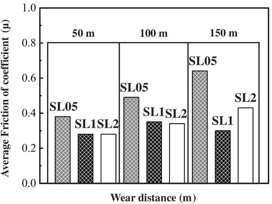
Figure 7: Average friction coefficient of PMMA/SiO2/Br-Lignin composites (SiO2 and Br-Lignin 0.5 wt%, 1 wt%, 2 wt%) under different sliding distances
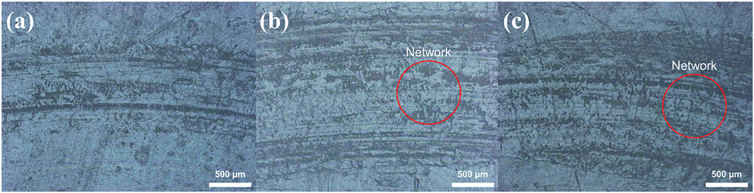
Figure 8: Wear track morphology of the SL05 sample at (a) 50 m, (b) 100 m, and (c) 150 m
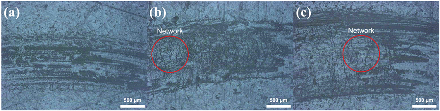
Figure 9: Morphology of wear tracks on SL1 at (a) 50 m, (b) 100 m, and (c) 150 m
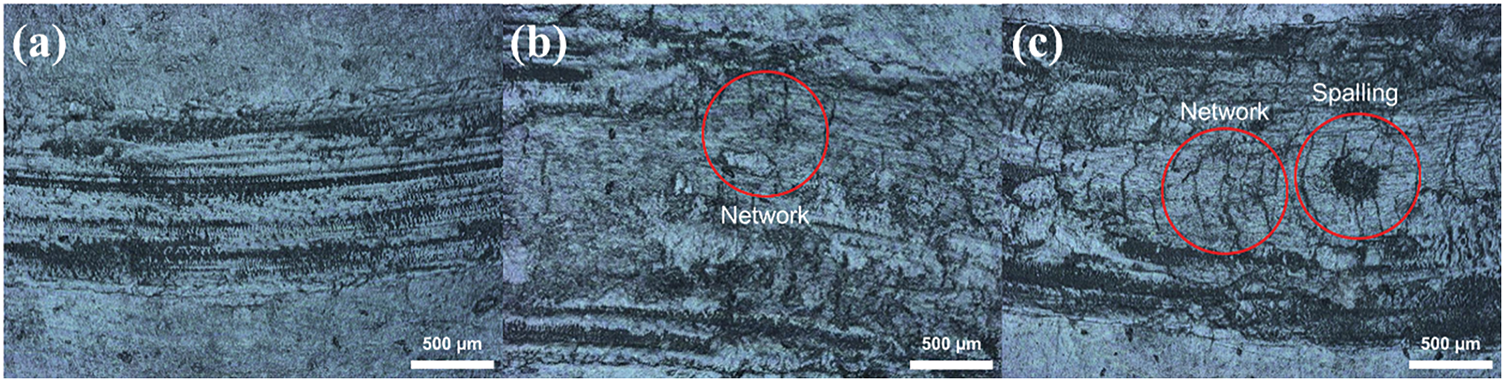
Figure 10: Morphology of wear tracks on SL2 at (a) 50 m, (b) 100 m, and (c) 150 m
At 100 m, adhesive wear (S1M3) remained dominant, and the wear track began to exhibit irregular morphology, suggesting that the Br-Lignin network structure was gradually exposed and damaged. As the internal support within the lubricating layer (S3M3) deteriorated, the functions of Qr and Qi progressively failed. This degradation in third-body flow made it difficult to sustain lubrication, causing the friction coefficient to increase steadily.
By 150 m, surface irregularities became more pronounced as extended sliding further removed the Br-Lignin network. At this point, Qi and Qr failed, and the third-body layer (S3) lost its protective capacity (S3M2). The wear mechanism transitioned to severe adhesive wear (S1M3), with significantly intensified surface damage and the highest observed friction coefficient.
Table 5 summarizes the adaptive behavior modes and third-body flow mechanisms of the SL05 sample under various sliding speeds, facilitating a better understanding of its dynamic wear evolution.
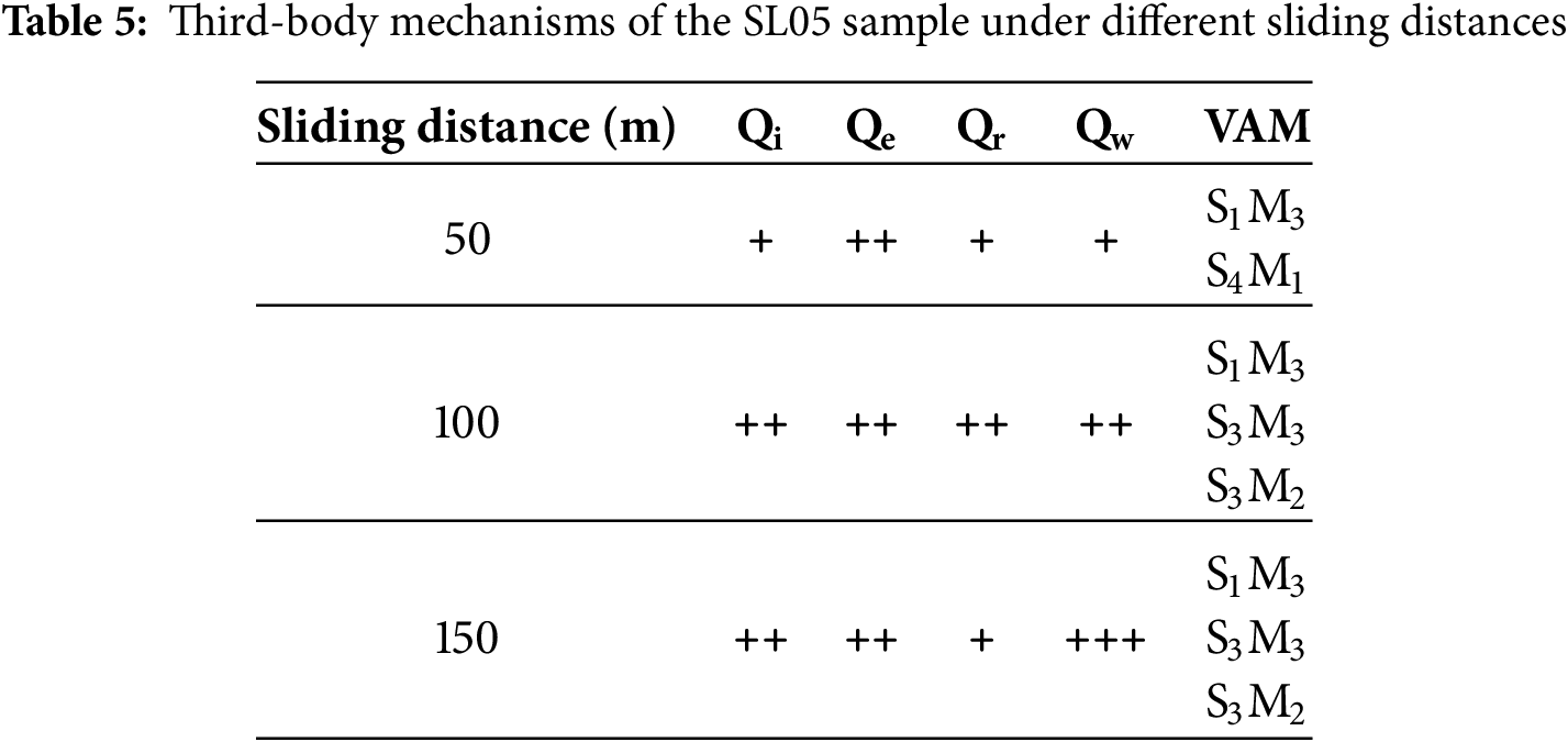
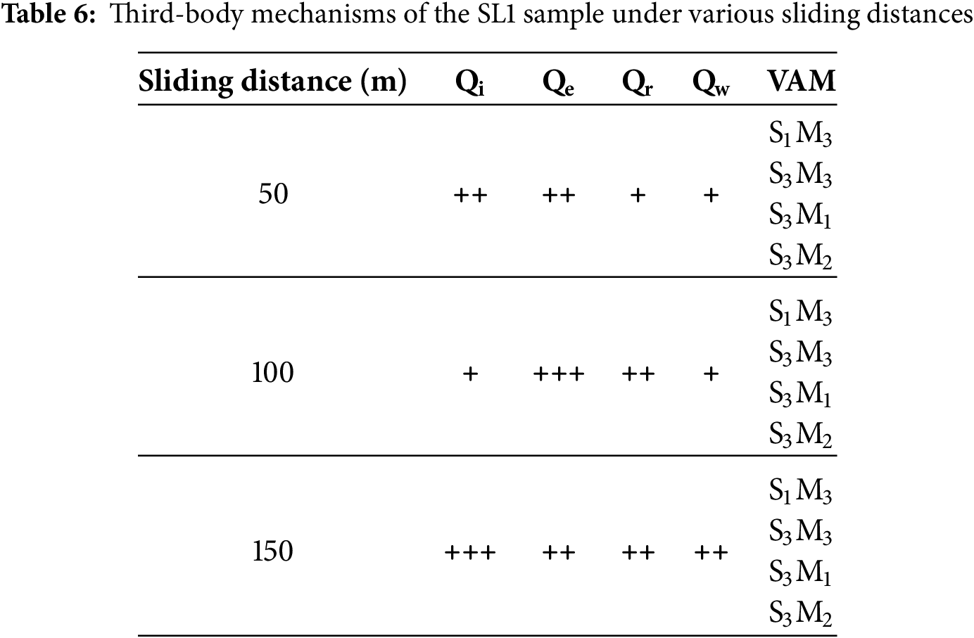
Fig. 9 shows that adhesive wear (S1M3) dominates under all three sliding distances. This wear mechanism is likely due to the dual fillers being chemically grafted onto the matrix, creating strong interfacial bonding. During wear, debris tends to adhere to more substrate material, resulting in more severe surface damage. At 100 m, the removal of the net-like structure is most pronounced, confirming that in this system, the Br-Lignin-based network structure governs the lubrication behavior by increasing the resistance to particle removal (S3M3).
This network structure contributes to a stable lubricating layer during wear, actively participating in load support and shear deformation, corresponding to Qi in the third-body flow. However, sliding progresses, the third-body layer deteriorates (S3M2), and lubrication becomes ineffective. This mechanism leads to the emergence of pronounced Qe, disrupting interfacial stability and causing a sharp increase in the friction coefficient, which reaches a maximum value at 100 m.
Table 6 summarizes the adaptive behavior modes and third-body flow mechanisms of the SL1 sample under various sliding speeds, facilitating a better understanding of its dynamic wear evolution.
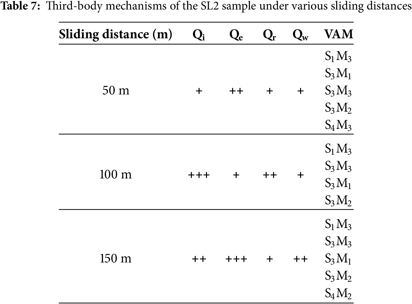
As shown in Fig. 10a, the wear behavior is dominated by adhesive wear [S1M3], accompanied by visible abrasive grooves indicative of plowing action [S4M3]. However, the limited surface discoloration and minor material loss suggest that overall damage remains moderate, with no significant delamination or severe structural failure. This behavior may be attributed to the transient involvement of third-body particles in the contact zone, which are rapidly expelled (Qe) after brief shearing interaction, preventing the establishment of a stable lubricating layer and limiting structural degradation.
In Fig. 10b, at a sliding distance of 100 m, adhesive wear traces [S1M3] and the partial exposure of the lignin-based network structure become evident. This observation reveals a consistent wear trend across the SL series, where increased sliding promotes progressive degradation of the protective network. As the structural integrity of the third-body layer diminishes [S3M2], the lubrication capacity weakens, and the friction coefficient increases accordingly.
Fig. 10c shows more severe exposure and removal of the network structure. This evidence may result from the extended sliding distance but also from the excessive content of Br-Lignin at this formulation ratio, which leads to densely packed or even agglomerated network regions. Under high shear stress, these dense zones fail to distribute stress effectively, becoming focal points for catastrophic failure. Rapid detachment of large network segments occurs, with visible signs of full delamination. This results in the complete loss of Br-Lignin’s reinforcement capability [S3M2], accelerating wear deterioration. As the lubricating layer is extensively removed, the third-body flow mechanisms (Qi and Qr) are disrupted, while expulsion of particles dominates (Qe). Without lubrication or shear support, the wear mechanism reverts to severe adhesive wear [S1M3], producing the highest observed friction coefficient.
Table 7 summarizes the adaptive behavior modes and third-body flow mechanisms of the SL2 sample under various sliding conditions, contributing to the overall understanding of its dynamic wear evolution.
The average friction coefficient of the PMMA/SiO2/Br-Lignin/CNCs composite at various sliding distances is illustrated in Fig. 11, while Figs. 12–14 depict the corresponding surface morphologies at each distance.
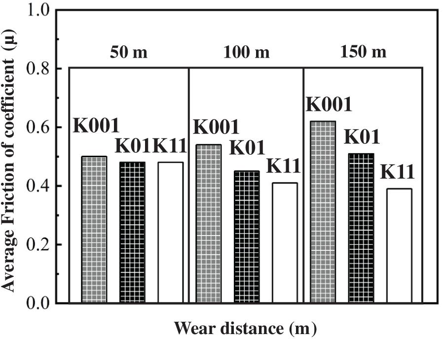
Figure 11: Average friction coefficient of PMMA/SiO2/Br-Lignin/CNCs composites (SiO2 and Br-Lignin 1 wt%; CNCs 0.01 wt%, 0.1 wt%, and 1 wt%) under different sliding distances
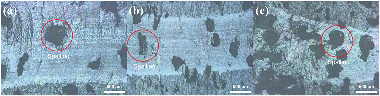
Figure 12: Morphology of wear tracks on K001 at (a) 50 m, (b) 100 m, and (c) 150 m
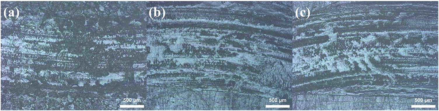
Figure 13: Morphology of wear tracks on K01 at (a) 50 m, (b) 100 m, and (c) 150 m
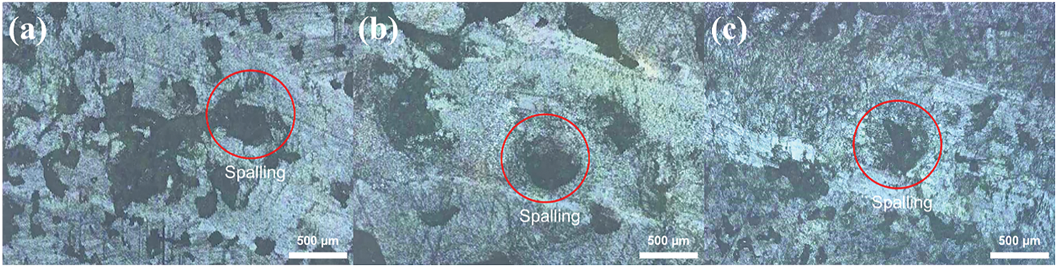
Figure 14: Morphology of wear tracks on K11 at (a) 50 m, (b) 100 m, and (c) 150 m
As shown in Fig. 12, the wear scars at all sliding distances exhibit consistent morphology, with evident delamination marks [S4M2] appearing within the uniform grooves. These delamination features progressively worsen with increased distance, indicating a discrepancy between surface wear stability and actual frictional behavior. This result may result from poor dispersion between SiO2 and the macromolecular Br-Lignin, where low or uneven CNCs content provides insufficient toughening to retard crack propagation and local failure.
From the perspective of third-body flow, the smooth wear surface suggests short-term stable contact behavior, with signs of lubrication layer formation corresponding to [Qi] and [Qr]. The delamination marks imply that the lubrication was not fully maintained under increasing stress. Thus, while macroscopic wear tracks appear uniform, subsurface degradation continues to evolve with sliding distance.
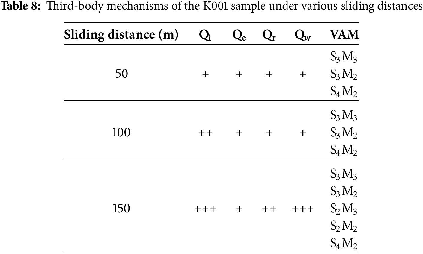
Table 8 summarizes the adaptive wear behavior patterns and third-body flow mechanisms of the K001 sample under different speed conditions, providing insight into the evolution of its dynamic tribological behavior.
As shown in Fig. 13, the wear tracks are dominated by adhesive wear, with no apparent signs of delamination or cracking, indicating that K01 (0.1 wt% CNCs) provides better toughening performance than K001. The friction coefficient remains relatively consistent across all three sliding distances, demonstrating the adaptability of composite to distance variations. From the perspective of third-body flow, the localized material removal and transfer during adhesive wear suggest an external outflow behavior [Qe].
The fine sliding marks and uniform contact features observed in the wear scars imply that the abrasive particles continue to participate in energy dissipation and lubrication under the influence of [Qi] and [Qr]. This stable third-body flow behavior helps mitigate surface damage and maintain a stable friction coefficient.
Table 9 summarizes the adaptive wear behavior patterns and third-body flow mechanisms of the K01 sample under different sliding conditions, contributing to a more comprehensive understanding of its dynamic tribological evolution.
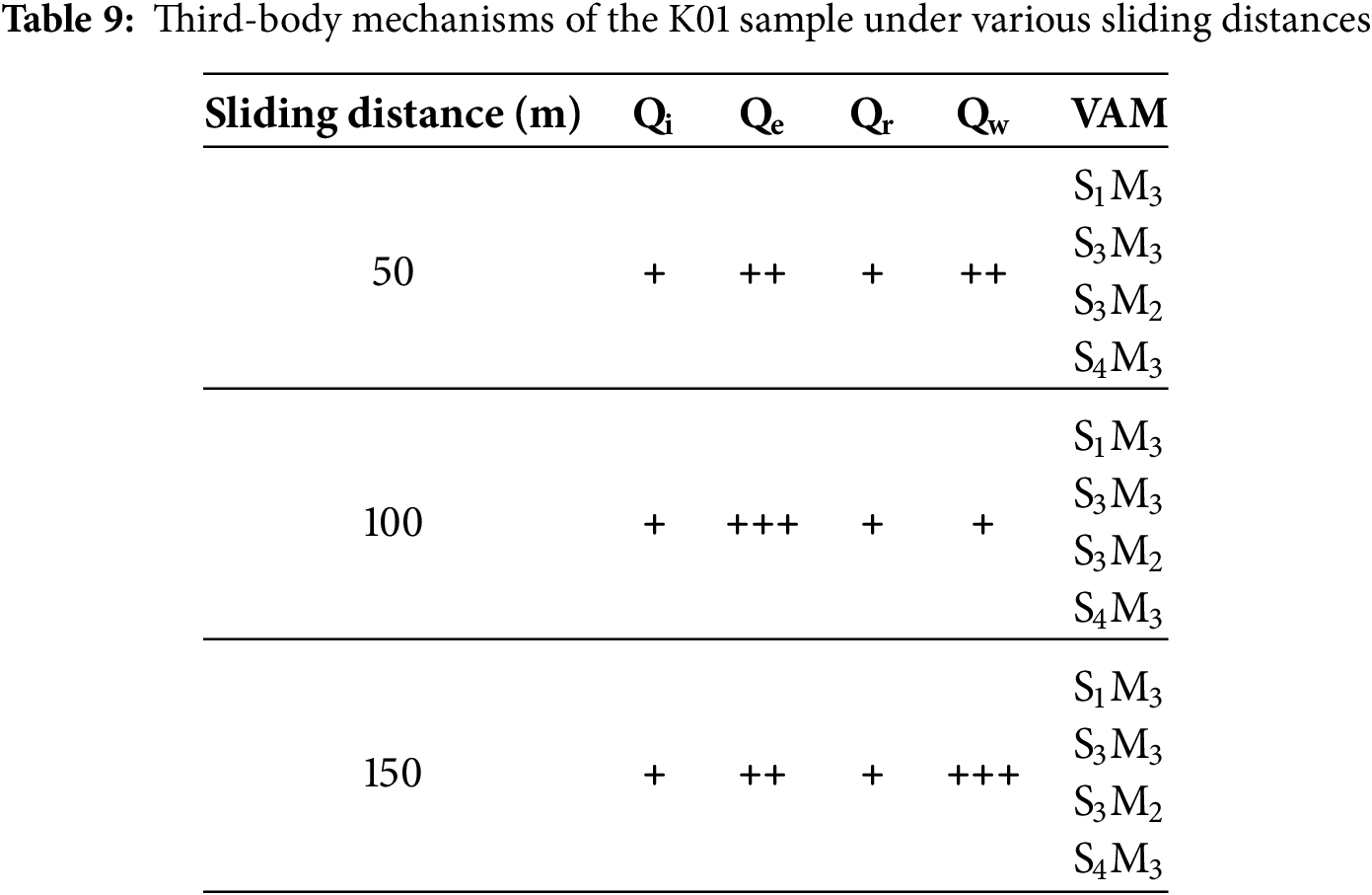
Fig. 14 shows delamination [S4M2] is observed within the wear track, but the severity gradually decreases with increased sliding distance. This behavior is attributed to the agglomeration and poor dispersion of CNCs when the content reaches 1 wt%, which induces localized stress concentration and initiates surface delamination. However, as the sliding progresses, a third-body lubricating layer gradually forms and stabilizes in the contact zone [S2M3], effectively sharing the applied load, reducing contact stress, and protecting the surface, resulting in a decreasing trend in the friction coefficient of K11 with sliding distance.
From the perspective of third-body flow, relatively uniform wear tracks are observed at all distances, indicating that the abrasives continuously participate in sliding through [Qi]. Due to the higher surface hardness of the material, the wear track boundaries are less defined, and features of [Qr] are less pronounced, suggesting minimal edge accumulation and restructuring of wear debris. Notably, at 50 m, surface delamination is more evident, suggesting extensive particle ejection and removal, corresponding to strong [Qe] and [Qw] behaviors.
Table 10 summarizes the adaptive wear behaviors and third-body flow mechanisms of the K11 sample under different sliding conditions, providing insights into its dynamic tribological evolution.

Wear Rate Analysis
This section investigates the effects of three compositional ratios under each material system. Bar graphs illustrate the wear rate trends across three different sliding distances for each combination.
As shown in Fig. 15, the wear rate of S5 first decreases and then increases with sliding distance. According to Fig. 4, at 50 m, deep and discontinuous plowing grooves were observed in the wear track, resulting in significant material removal and a relatively high wear rate. At 100 m, the wear mechanism shifted, and adhesive wear led to material being pulled together with the counterface, reducing groove depth and stabilizing the wear behavior. At 150 m, the wear track became more evenly distributed and thoroughly covered the contact area, indicating the system had entered a stable sliding wear stage. Although total material loss continued to increase with distance, the wear rate remained lower than that at 50 m.
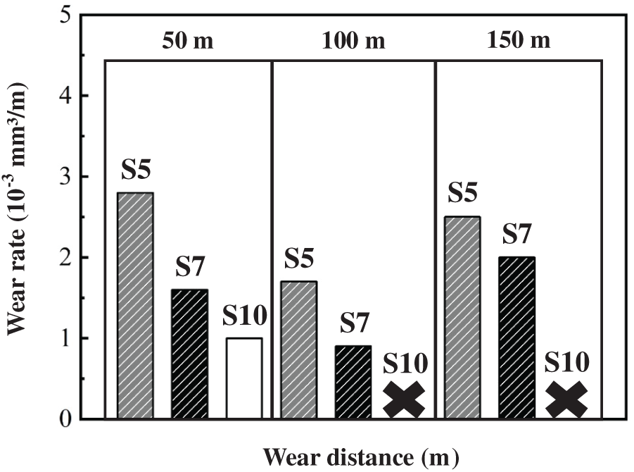
Figure 15: Wear rate analysis of PMMA/SiO2 composites (SiO2 at 5 wt%, 7 wt%, and 10 wt%) under different sliding distances
In Fig. 15, S7 exhibited shallower adhesive wear marks during the wear process. This wear facilitated the formation of a more stable contact interface, leading to a lower wear rate than S5. However, at 150 m, microcracks and scratch marks began to appear, destabilizing the wear behavior and forming several grooves, consequently raising the wear rate.
As shown in Fig. 6, no significant wear marks were observed on the surface of S10 at 50 m due to the short sliding distance, although signs of delamination had begun to appear. With increased sliding distance, severe plowing became evident, resulting in brittle fractures and delamination. The dominant wear mechanism involved particle detachment via delamination, and no continuous or uniform wear track developed. During the 100 and 150 m tests, the friction coefficient exceeded the instrument’s upper measurement limit, leading to early test termination. This behavior deviated from the expected local reinforcement effect of SiO2. Although the addition of SiO2 did enhance the material’s rigidity, its reinforcing effect was insufficient to offset the associated brittleness.
As shown in Fig. 16, the wear rate gradually decreases with increasing Br-Lignin content, confirming the expected role of the Br-Lignin network structure in enhancing material resistance to removal. This trend is consistent with the friction coefficient analysis presented in Figs. 8–10, where the network structure exhibits progressive removal with increasing sliding distance.
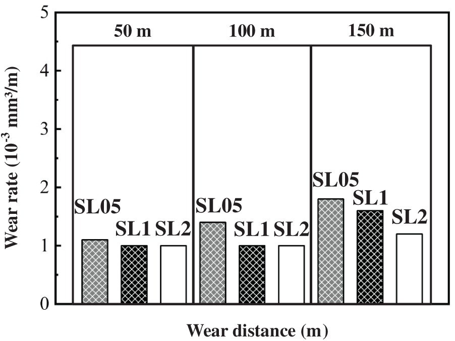
Figure 16: The wear rate analysis of PMMA/SiO2/Br-Lignin composites with SiO2 and Br-Lignin contents of 0.5 wt%, 1 wt%, and 2 wt% under different sliding distances
As shown in Fig. 17, the wear rates remained relatively low prior to the 100 m sliding distance, with minimal differences among the various filler ratios. Observations from Figs. 12–14 indicate that the wear tracks at these shorter distances were generally uniform and exhibited similar coloration to the matrix, suggesting shallow penetration, consistent with the enhanced hardness observed in the K-series samples.
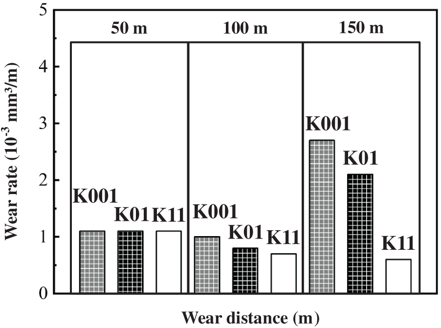
Figure 17: The wear rate analysis of PMMA/SiO2/Br-Lignin/CNCs composites containing 1 wt% SiO2 and Br-Lignin, and varying CNCs contents of 0.01 wt%, 0.1 wt%, and 1 wt%, under different sliding distances
At 150 m, however, both K001 and K01 samples exhibited severe delamination and plowing. This instability was attributed to excessive surface roughness within the wear track, leading to flake-like wear debris detachment. The sample exhibited the highest hardness with the CNCs content increased to 1 wt%. While some delamination still occurred, the wear tracks were less pronounced. This behavior aligns with the expected synergistic effect of multi-filler reinforcement. Nonetheless, once the fillers became exposed during the wear process, they might have contributed to the increased wear rate.
The performance trends observed in our ternary PMMA/SiO2/Br-Lignin/CNCs composite align with broader advances in multifunctional PMMA composites. Zhao et al. [34] demonstrated that PMMA can be leveraged as a sacrificial pore-forming agent in porous, self-lubricating grinding wheels, where its decomposition produced controlled porosity for coolant retention and chip storage, while Ni-coated MoS2 fillers reduced the friction coefficient by 22.7% and improved surface roughness by 30.45%.
Additionally, Kumari et al. [35] fabricated MgO-reinforced PMMA composites for dental applications and reported compressive strength up to 101 MPa, Young’s modulus of 0.79 GPa, fracture toughness of 9.8 MPa·m1/2, and a significant wear-volume reduction (nearly 80%) compared to pristine PMMA.
These results parallel our findings that bio-inorganic ternary fillers not only increase hardness and reduce wear but also enhance interfacial stability and third-body layer formation. Both studies highlight PMMA’s versatility as a base or sacrificial phase for tribology-driven design.
This study successfully developed PMMA-based composites with enhanced tribological performance by strategically integrating multiple fillers, including nano-SiO2, Br-Lignin, and CNCs. When combined in optimal ratios, it was hypothesized that the synergistic effect of inorganic and bio-based fillers would significantly improve surface hardness and wear resistance by enabling dynamic third-body lubrication mechanisms and microstructural reinforcement.
Experimental results validated this hypothesis. Proper filler compositions increased the composite hardness by up to 20%, significantly improving the scratch resistance. Furthermore, the friction coefficient decreased by as much as 38%, and the wear rate was reduced by 78%, confirming the strong synergistic interactions among the multi-filler system in resisting wear. Among all tested formulations, the K01 composite exhibited the best overall performance, achieving a 15% increase in hardness and reductions of 15% in friction coefficient and 78% in wear rate.
These outcomes highlight the critical role of co-regulating filler type and content in tailoring the tribological behavior of polymer composites. In summary, this study demonstrates that a multi-filler grafting strategy can effectively optimize the tribo-mechanical properties of PMMA composites. The findings provide a promising approach for developing polymer materials suitable for high-wear applications and a valuable design framework for next-generation durable polymer composites.
It should be noted that this work was conducted on a single batch of specimens, and therefore batch-to-batch stability (e.g., reproducibility of hardness and wear rate values) could not be evaluated. This limitation will be addressed in future investigations.
Future studies may integrate multi-criteria decision-making techniques to systematically rank the optimal formulations. Approaches such as Entropy-VIKOR, FAHP-FTOPSIS, and AHP-TOPSIS could simultaneously evaluate hardness, friction coefficient, and wear rate, thereby providing a structured framework for material selection. In addition, future research should also explore surface modification of fillers to improve dispersion and investigate the incorporation of solid lubricants to further enhance friction reduction and wear resistance.
Acknowledgement: The authors gratefully acknowledge the Core Facility Center of National Cheng Kung University (NCKU), Taiwan, for providing access to equipment EM000600, funded under NSTC project No. 114-2740-M-006-001. Additional support from the Higher Education Sprout Project, Ministry of Education, Taiwan, through the Headquarters of University Advancement at NCKU, is also gratefully acknowledged.
Funding Statement: This work was supported by the National Science and Technology Council (NSTC), Taiwan (Grant Nos. 113-2221-E-006-087-MY2, 113-2221-E-006-112-MY2, and 114-2221-E-006-090).
Author Contributions: Du-Yi Wang: Investigation, Software, Visualization, Writing—Original Draft. Shih-Chen Shi: Supervision, Methodology, Resources, Funding Acquisition, Writing—Original Draft. Dieter Rahmadiawan: Formal Analysis, Writing—Review & Editing, Validation. All authors reviewed the results and approved the final version of the manuscript.
Availability of Data and Materials: The data that support the findings of this study are available from the Corresponding Author, [Shih–Chen Shi], upon reasonable request.
Ethics Approval: Not applicable.
Conflicts of Interest: The authors declare no conflicts of interest to report regarding the present study.
References
1. Ammarullah MI, Hartono R, Supriyono T, Santoso G, Sugiharto S, Permana MS. Polycrystalline diamond as a potential material for the hard-on-hard bearing of total hip prosthesis: von mises stress analysis. Biomedicines. 2023;11(3):951. doi:10.3390/biomedicines11030951. [Google Scholar] [CrossRef]
2. Yadav R, Lee HH. Fabrication, characterization, and selection using FAHP-TOPSIS technique of zirconia, titanium oxide, and marble dust powder filled dental restorative composite materials. Polym Adv Technol. 2022;33(10):3286–95. doi:10.1002/pat.5780. [Google Scholar] [CrossRef]
3. Yadav R. Fabrication, characterization, and optimization selection of ceramic particulate reinforced dental restorative composite materials. Polym Polym Compos. 2022;30:09673911211062755. doi:10.1177/09673911211062755. [Google Scholar] [CrossRef]
4. Yadav R, Singh M, Shekhawat D, Lee SY, Park SJ. The role of fillers to enhance the mechanical, thermal, and wear characteristics of polymer composite materials: a review. Compos Part A Appl Sci Manuf. 2023;175(4):107775. doi:10.1016/j.compositesa.2023.107775. [Google Scholar] [CrossRef]
5. Yadav R, Meena A, Lee SY, Park SJ. Experimental tribological and mechanical behavior of aluminium alloy 6061 composites incorporated ceramic particulates using Taguchi analysis. Tribol Int. 2024;192(1):109243. doi:10.1016/j.triboint.2023.109243. [Google Scholar] [CrossRef]
6. Yadav R, Lee HH, Meena A, Sharma YK. Effect of alumina particulate and E-glass fiber reinforced epoxy composite on erosion wear behavior using Taguchi orthogonal array. Tribol Int. 2022;175:107860. doi:10.1016/j.triboint.2022.107860. [Google Scholar] [CrossRef]
7. Yadav R, Sonwal S, Sharma YK, Huh YS, Brambilla E, Khan R, et al. A mini review on physical, mechanical, tribology analysis of micro-nano fibers and ceramics reinforced polymer composites for advanced manufacturing processes. Polym Adv Technol. 2025;36(5):e70205. doi:10.1002/pat.70205. [Google Scholar] [CrossRef]
8. Zhao L, Peng R, Gao J, Li Y, Wang J, Huang X. Strengthening mechanism of tribological properties of graphene oxide/multiwalled carbon nanotubes hybrid nanofluids: molecular dynamics and experimental validation. J Colloid Interface Sci. 2025;689(1):137154. doi:10.1016/j.jcis.2025.02.162. [Google Scholar] [PubMed] [CrossRef]
9. Huang TT, Rahmadiawan D, Shi SC. Synthesis and characterization of porous silica and composite films for enhanced CO2 adsorption: a circular economy approach. J Mater Res Technol. 2024;32(1):1460–8. doi:10.1016/j.jmrt.2024.08.003. [Google Scholar] [CrossRef]
10. Zhao L, Peng R, Gao J, Li Y, Tang X, Chen X, et al. Synergistic nanofluids-porous self-lubricating internal cooling wheel for superalloy grinding. Int J Mech Sci. 2025;302:110576. doi:10.1016/j.ijmecsci.2025.110576. [Google Scholar] [CrossRef]
11. Maximize Market Research. Polymethyl Methacrylate Market—Global Industry Analysis and Forecast (2024-2030) [Internet]. 2024 [cited 2025 Otc 22]. Available from: https://www.psmarketresearch.com/market-analysis/polymethyl-methacrylate-pmma-market. [Google Scholar]
12. Shi S-C, Rao H-W, Rahmadiawan D. Enhanced-optical-measurement-and-stress-quantification-of-film-roll-wrinkling-in-roll-to-roll-processing. Soc Mech Eng. 2025;46:223–31. [Google Scholar]
13. Rahmadiawan D, Abral H, Azka MA, Sapuan SM, Admi RI, Shi SC, et al. Enhanced properties of TEMPO-oxidized bacterial cellulose films via eco-friendly non-pressurized hot water vapor treatment for sustainable and smart food packaging. RSC Adv. 2024;14(40):29624–35. doi:10.1039/d4ra06099g. [Google Scholar] [PubMed] [CrossRef]
14. Chou CT, Shi SC, Chen CK. Sandwich-structured, hydrophobic, nanocellulose-reinforced polyvinyl alcohol as an alternative straw material. Polymers. 2021;13(24):4447. doi:10.3390/polym13244447. [Google Scholar] [PubMed] [CrossRef]
15. Shi SC, Chen TH, Mandal PK. Enhancing the mechanical and tribological properties of cellulose nanocomposites with aluminum nanoadditives. Polymers. 2020;12(6):1246. doi:10.3390/polym12061246. [Google Scholar] [PubMed] [CrossRef]
16. Dong S, Chen T, Fu H, Chen X, Zhou C. Mechanical response and interface properties of graphene-metal composites: a review. J Mater Res Technol. 2025;36:398–416. doi:10.1016/j.jmrt.2025.03.094. [Google Scholar] [CrossRef]
17. Shi SC, Cheng ST, Rahmadiawan D. Developing biomimetic PVA/PAA hydrogels with cellulose nanocrystals inspired by tree frog structures for superior wearable sensor functionality. Sens Actuat A Phys. 2024;379(2):115981. doi:10.1016/j.sna.2024.115981. [Google Scholar] [CrossRef]
18. do Nascimento NR, Pinheiro IF, Alves GF, Mei LHI, de Macedo Neto JC, Morales AR. Role of cellulose nanocrystals in epoxy-based nanocomposites: mechanical properties, morphology and thermal behavior. Polímeros. 2021;31(3):e2021034. doi:10.1590/0104-1428.20210057. [Google Scholar] [CrossRef]
19. Song H, Zheng L. Nanocomposite films based on cellulose reinforced with nano-SiO2: microstructure, hydrophilicity, thermal stability, and mechanical properties. Cellulose. 2013;20(4):1737–46. doi:10.1007/s10570-013-9941-3. [Google Scholar] [CrossRef]
20. Wang Y, Kalscheur J, Ebikade E, Li Q, Vlachos DG. LigninGraphs: lignin structure determination with multiscale graph modeling. J Cheminform. 2022;14(1):43. doi:10.1186/s13321-022-00627-2. [Google Scholar] [PubMed] [CrossRef]
21. Stéphan C, Nguyen TP, de la Chapelle ML, Lefrant S, Journet C, Bernier P. Characterization of singlewalled carbon nanotubes-PMMA composites. Synth Met. 2000;108(2):139–49. doi:10.1016/S0379-6779(99)00259-3. [Google Scholar] [CrossRef]
22. Vallés C, Papageorgiou DG, Lin F, Li Z, Spencer BF, Young RJ, et al. PMMA-grafted graphene nanoplatelets to reinforce the mechanical and thermal properties of PMMA composites. Carbon. 2020;157:750–60. doi:10.1016/j.carbon.2019.10.075. [Google Scholar] [CrossRef]
23. Arockiasamy FS, Manoharan B, Santhi VM, Prakalathan K, Periasamy D, Dhandapani A, et al. Navigating the nano-world future: harnessing cellulose nanocrystals from green sources for sustainable innovation. Heliyon. 2024;11(1):e41188. doi:10.1016/j.heliyon.2024.e41188. [Google Scholar] [PubMed] [CrossRef]
24. Fuseini M, Yousry Zaghloul MM, Abakar D, Yousry Zaghloul MM. Review of epoxy nano-filled hybrid nanocomposite coatings for tribological applications. FlatChem. 2025;49:100768. doi:10.1016/j.flatc.2024.100768. [Google Scholar] [CrossRef]
25. Shojaeiarani J, Bajwa D, Holt G. Sonication amplitude and processing time influence the cellulose nanocrystals morphology and dispersion. Nanocomposites. 2020;6(1):41–6. doi:10.1080/20550324.2019.1710974. [Google Scholar] [CrossRef]
26. Steiner G, Zimmerer C, Salzer R. Characterization of metal-supported poly(methyl methacrylate) microstructures by FTIR imaging spectroscopy. Langmuir. 2006;22(9):4125–30. doi:10.1021/la053221x. [Google Scholar] [PubMed] [CrossRef]
27. Zong E, Liu X, Liu L, Wang J, Song P, Ma Z, et al. Graft polymerization of acrylic monomers onto lignin with CaCl2–H2O2 as initiator: preparation, mechanism, characterization, and application in poly(lactic acid). ACS Sustainable Chem Eng. 2018;6(1):337–48. doi:10.1021/acssuschemeng.7b02599. [Google Scholar] [CrossRef]
28. Rao A, Divoux T, Owens CE, Hart AJ. Printable, castable, nanocrystalline cellulose-epoxy composites exhibiting hierarchical nacre-like toughening. Cellulose. 2022;29(4):2387–98. doi:10.1007/s10570-021-04384-7. [Google Scholar] [CrossRef]
29. Wang R, Xiong Y, Yang K, Zhang T, Zhang F, Xiong B, et al. Advanced progress on the significant influences of multi-dimensional nanofillers on the tribological performance of coatings. RSC Adv. 2023;13(29):19981–20022. doi:10.1039/d3ra01550e. [Google Scholar] [PubMed] [CrossRef]
30. Pajer N, Cestari C, Argyropoulos DS, Crestini C. From lignin self assembly to nanoparticles nucleation and growth: a critical perspective. npj Mater Sustain. 2024;2(1):31. doi:10.1038/s44296-024-00037-5. [Google Scholar] [CrossRef]
31. Hilburg SL, Elder AN, Chung H, Ferebee RL, Bockstaller MR, Washburn NR. A universal route towards thermoplastic lignin composites with improved mechanical properties. Polymer. 2014;55(4):995–1003. doi:10.1016/j.polymer.2013.12.070. [Google Scholar] [CrossRef]
32. Iordanoff I, Berthier Y, Descartes S, Heshmat H. A review of recent approaches for modeling solid third bodies. J Tribol. 2002;124(4):725–35. doi:10.1115/1.1467632. [Google Scholar] [CrossRef]
33. Descartes S, Berthier Y. Rheology and flows of solid third bodies: background and application to an MoS1.6 coating. Wear. 2002;252(7–8):546–56. doi:10.1016/S0043-1648(02)00008-X. [Google Scholar] [CrossRef]
34. Zhao L, Peng R, Gao J, Li Y, Chen M. Mechanistic design of porous self-lubricating grinding wheels with integrated internal cooling: role of PMMA and nickel-coated MoS2 composites in machining enhancement. J Mater Process Technol. 2025;340:118877. doi:10.1016/j.jmatprotec.2025.118877. [Google Scholar] [CrossRef]
35. Kumari S, Mishra RK, Parveen S, Avinashi SK, Hussain A, Kumar S, et al. Fabrication, structural, and enhanced mechanical behavior of MgO substituted PMMA composites for dental applications. Sci Rep. 2024;14(1):2128. doi:10.1038/s41598-024-52202-4. [Google Scholar] [PubMed] [CrossRef]
Cite This Article
 Copyright © 2025 The Author(s). Published by Tech Science Press.
This work is licensed under a Creative Commons Attribution 4.0 International License , which permits unrestricted use, distribution, and reproduction in any medium, provided the original work is properly cited.
 Downloads
 Citation Tools