
 Submit a Paper
 Propose a Special lssue
 Open Access
ARTICLE

Mechanical Performance and Deformation Mechanisms of Additively Manufactured Lattice Structures under Quasi-Static Compression and Finite Element Analysis
1 Department of Mechanical & Manufacturing Engineering, Faculty Engineering & Built Environment, Universiti Kebangsaan Malaysia, Bangi, Selangor, Malaysia
2 Institute of Advanced Materials and Technology, Guangdong University of Technology, Guangzhou, 510006, China
* Corresponding Author: Nabilah Afiqah binti Mohd Radzuan. Email:
Journal of Polymer Materials 2026, 43(2), 18 https://doi.org/10.32604/jpm.2026.077219
Received 04 December 2025; Accepted 17 March 2026; Issue published 30 June 2026
 View Full Text
 Download PDF
Abstract
Lattice structures fabricated through additive manufacturing (AM) offer exceptional strength-to-weight ratios, as their geometries allow them to carry high loads with far less material than solid components. When paired with polylactic acid (PLA), they combine biodegradability with ease of processing, allowing the structures to be produced efficiently while also offering an environmentally friendly material option. However, comparative studies across different lattice types under uniform conditions remain limited, as many existing studies only focus on a single geometry type. Therefore, this study investigates the compressive performance of PLA lattice structures, which include body-centered cubic (BCC), honeycomb and gyroid, fabricated using fused deposition modelling (FDM). To ensure consistent mechanical performance and mitigate variability from commercial filaments, the PLA filaments used were produced in-house from raw pellets. This approach enhances material homogeneity and repeatability, which is critical for reliable comparative analysis. Quasi-static compression tests and finite element analysis (FEA) were conducted to evaluate the mechanical properties and deformation mechanisms. Results revealed that the gyroid structure outperformed the other structures, showing a 44% higher elastic modulus (199.56 MPa) and 60% higher compressive strength (6.64 MPa). The continuous topology of the gyroid structure enabled a uniform stress distribution throughout the lattice and enhanced energy absorption by promoting progressive deformation under load. Simulation results aligned with experimental trends, though slight overestimations occurred due to idealized modelling such as perfect geometry and material homogeneity. This work provides validated numerical models and practical insights for designing sustainable lightweight components in engineering applications.Graphic Abstract
Keywords
Additive manufacturing (AM) has undergone rapid evolution since its beginning in the 1980s, transitioning from a tool primarily used for rapid prototyping to a full-scale production technology capable of fabricating complex, customized components across various industries [1]. Among the numerous AM techniques, fused deposition modelling (FDM) is particularly valued for its cost-effectiveness, material versatility and ability to produce intricate geometries such as lattice structures without the need for support structures [2]. This process involves the layer-by-layer extrusion of thermoplastic filaments such as polylactic acid (PLA), which is widely used due to its biodegradability, ease of processing and renewable sourcing [3]. Lattice structures, characterized by their periodic arrangement of unit cells, have emerged as a key area of interest within AM due to their exceptional strength-to-weight ratios, efficient material usage and potential for tailored mechanical performance [4]. These architectures are especially promising for applications that require lightweight yet strong components, making them suitable for sectors ranging from biomedical engineering to aerospace.
Lattice structures are broadly categorized into several types including strut-based designs such as cubic lattices and sheet-based designs such as triply periodic minimal surface (TPMS) lattices, each with distinct architectural characteristics and mechanical behaviours under load [5]. These categories of lattice structures can be seen in Fig. 1a,b for cubic lattices and in Fig. 1c–e for TPMS lattices. For instance, body-centered cubic (BCC) lattices have shown better mechanical performance compared to simple cubic (SC) designs, with studies reporting an elastic modulus of approximately 100 MPa for BCC structures, significantly higher than the 70 MPa observed for SC structures with an identical 3 × 3 × 3 cell configuration. This represents an increase of about 43%, highlighting the impact of nodal interconnectivity on stiffness and load distribution [6]. Among TPMS structures, the gyroid has consistently outperformed other sheet-based designs in compression tests. Research has shown that the gyroid structure exhibits a higher plateau stress of 50 MPa compared to 45 MPa for i-wrapped periodic (IWP), representing an 11% improvement. It also shows a greater specific energy absorption of 11 J/g compared to 10 J/g, a 10% increase that demonstrates its higher efficiency in dissipating energy [7]. Further strengthening this comparison, other studies found that gyroid structures reached a yield strength of 64.2 MPa, which is about 32% higher than the 48.8 MPa recorded for primitive structures. This enhancement is attributed to the gyroid’s continuous, smooth curvature which mitigates stress concentration and promotes homogeneous deformation [8]. These documented performance differentials highlight the critical influence of topological design on the compressive response of lattice structures.

Figure 1: Unit cell of (a) BCC, (b) SC, (c) Gyroid, (d) IWP and (e) Primitive [6,9].
Despite the vast amount of research on the performance of lattice structures, a significant gap remains in the direct comparative assessment of different lattice types under compression testing with identical manufacturing and testing conditions. Many previous studies have focused on a single lattice type, often employing metals such as 316L stainless steel or polymers such as polyamide, which limits the relevance of their findings to PLA-based systems and hinders an overall understanding of how these competing structures perform relative to one another [10,11]. Moreover, many comparative studies in FDM rely on commercially sourced filaments, which can exhibit significant batch-to-batch variability in diameter, crystallinity and mechanical properties due to differing manufacturing processes and storage conditions. One study reported that conventional polyamide filaments present challenges such as warping and distortion when exposed to heat, as they often lack tailored thermal stability and are difficult to control, limiting their performance in high-temperature environments [3,12]. This limits the generalizability of findings and highlights the need for studies employing tightly controlled material processing. Furthermore, while numerical simulations such as finite element analysis (FEA) conducted using ANSYS software are a powerful predictive tool, few studies have integrated them with physical compression tests within a single framework to validate computational models and comprehensively examine both the mechanical properties and deformation mechanisms of these intricate structures [13]. This disconnect between simulation and experimentation often overlooks FDM-specific defects such as layer adhesion inconsistencies and geometric inaccuracies, which are critical for accurately predicting real-world performance [14,15]. To contextualize the present study within the broader landscape of existing research, a summary of studies on additively manufactured lattice structures evaluated under compression testing is presented in Table 1. This classification categorizes selected studies based on lattice type, material, fabrication process and the investigation method used to determine mechanical properties.

Therefore, this study aims to comprehensively evaluate and compare the mechanical performance and deformation behaviour of three distinct lattice structures consisting of BCC, honeycomb and gyroid fabricated from PLA using FDM. This work further distinguishes itself by employing in-house extruded PLA filament, which enables controlled material consistency and minimizes variability commonly associated with commercial filaments. The primary objectives are to experimentally characterize the quasi-static compressive response of these structures in accordance with ASTM D695-23 standards, and to develop corresponding finite element models that accurately simulate their mechanical behaviour under identical loading conditions. Specifically, the research will quantify and compare key mechanical properties including elastic modulus, yield strength, compressive strength and plateau strength across all three lattice designs. Furthermore, the study seeks to analyse and correlate the deformation mechanisms observed during physical testing with simulated stress distributions and failure patterns obtained from FEA using ANSYS software. The selection of PLA as the base material is motivated by its biodegradability and suitability for FDM processing, while the choice of BCC, honeycomb and gyroid structures allows for a systematic investigation of how strut-based and sheet-based designs influence compressive performance in AM. Through this integrated experimental-simulation approach, the research will establish validated numerical models for predicting the compressive behaviour of PLA lattice structures and provide definitive performance rankings among the three structures.
The findings of this research hold significant implications for advancing sustainable manufacturing practices and lightweight design across multiple engineering sectors. By establishing validated computational models for predicting the mechanical behaviour of PLA lattice structures, this study provides reliable tools for enhancing material efficiency and structural performance in applications such as energy-absorbing components in the automotive industries [10]. The comparative analysis of BCC, honeycomb and gyroid topologies offers practical guidance for selecting appropriate lattice configurations based on specific mechanical requirements, thereby contributing to more efficient use of biodegradable polymers in load-bearing applications. This work supports responsible consumption and production by demonstrating how 3D-printed PLA lattices can achieve competitive mechanical performance while utilizing renewable resources and reducing material waste through cellular designs. The integration of experimental and simulation methodologies further establishes a framework for developing sustainable structures with enhanced mechanical properties and environmental credentials.
2.1 Structural Design and Fabrication
The initial phase of this research involved the structural design and AM of three distinct lattice structures, which are BCC, honeycomb and gyroid. These specific geometries were selected due to their prevalence in lightweight engineering applications and their contrasting mechanical behaviours under compressive loading, with BCC and honeycomb representing strut-based designs and the gyroid representing a continuous sheet-based design [5,25]. The computer-aided design (CAD) models of the three lattice structures are presented in Fig. 2. All lattice specimens were designed with overall dimensions of 30 mm × 30 mm × 30 mm, based on previous studies of a 3D-printed FDM sample and to ensure consistent comparative analysis between each specimen. The unit cell was standardized to a 3 × 3 × 3 configuration for all designs to maintain uniformity, while the wall thickness was adjusted to achieve a 30% volume ratio for each design to ensure printability and structural integrity during handling and testing [13,26].

Figure 2: CAD models of (a) BCC, (b) Honeycomb and (c) Gyroid structures.
The lattice structures were modelled using specialised CAD software, nTopology software (nTop Inc., USA), which is proficient in generating complex and parametrically controlled lattice geometries. The design process commenced with the creation of a solid base block matching the final specimen dimensions. The predefined unit cell libraries within nTop were then utilised to generate the BCC, honeycomb and gyroid unit cells. These unit cells were systematically arranged in all three spatial dimensions using the software’s cell map and patterning features to form the periodic lattice structures throughout the volume of the base block. Following the completion of the design, the lattice models were exported in Stereolithography (STL) file format, which is the standard for AM processes [27].
For filament fabrication, PLA 4043D pellets with an average diameter of 3 mm that are supplied by NatureWorks (Minnesota, USA) were used as the raw material. Before extrusion, the pellets were dried in a vacuum oven (Thermo Fisher Scientific, USA) at 80°C for 4 h to remove residual moisture, which could weaken layer adhesion and introduce porosity during subsequent processing stages [28]. The dried pellets were then melt-extruded into continuous filaments and wound onto spools under controlled conditions to maintain a consistent diameter of 1.75 mm, suitable for FDM printing. Key extrusion parameters included chamber temperatures ranging from 180°C to 200°C, an extruder speed of 5 rpm and a fan speed of 100%. This step ensured uniform melting behaviour and structural integrity across all printed lattices, thereby reducing a key source of experimental uncertainty prevalent in FDM-based studies [29].
Then, the fabrication of all lattice specimens was carried out using the FDM technique on a Funmat HT (Intamsys, China) 3D printer by utilizing the in-house fabricated PLA filament. Prior to printing, the STL files were imported into a slicing software, where the printing parameters were configured. The parameters, summarised in Table 2, were selected based on manufacturer recommendations and prior literature to achieve optimal layer adhesion and dimensional accuracy [30]. Key parameters included a 100% infill density to ensure the lattice struts were fully solid and free of voids, providing consistent material structure for accurate compression testing. Then, the fabricated samples were visually inspected for critical defects such as warping, delamination or incomplete printing, with defective samples were discarded and reprinted [28,31].

In addition, the accuracy of the 3D-printed lattice structure was verified by determining its mass and volume by comparing it with the designed structure. The measurements were conducted using Archimedes’ principle with distilled water as the immersion medium, where
2.2 Compression Testing Experiment
The experimental compression tests were conducted to evaluate the mechanical behaviour and deformation mechanisms of the three lattice structures under quasi-static uniaxial loading. The tests adhered to the international standard ASTM D695-23, which specifies the standard test method for compressive properties for rigid plastics such as PLA [27]. A Universal Testing Machine (UTM) Instron 5567 (Instron, USA) equipped with a 10 kN load cell was employed to apply and measure the compressive load for all the lattice structures and a data acquisition frequency of 10 Hz was maintained throughout each compression test. This machine was selected for its precision and capability to perform tests under controlled displacement rates, ensuring accurate and repeatable data acquisition. The compression platens of the UTM were thoroughly cleaned before each test to eliminate any debris or residue that might affect the contact surface or alignment [7,13].
During testing, each specimen was placed centrally on the lower compression platen to ensure uniform load distribution and to avoid eccentric loading conditions. The upper platen was then carefully lowered until it made light contact with the top surface of the specimen, as indicated by a slight preload reading. The system was subsequently reset to establish a consistent baseline for all tests. The compression tests were conducted in accordance with ASTM D695-23 under displacement control mode at a constant crosshead speed of 1.3 mm/min. This low strain rate was selected to minimise dynamic effects and allow the material to respond in a near-equilibrium manner, thereby capturing the true compressive behaviour of the PLA lattice structures [26,33]. A 10 kN load cell was used to accurately measure the applied compressive force throughout the test. The tests were performed until a strain level of 30% was reached, as this was sufficient to observe the full range of elastic deformation and plastic yielding without causing complete destruction of the specimen [34]. For each lattice geometry, five identical specimens were tested to ensure statistical reliability and to account for potential variability arising from the printing process.
Following the compression tests, the stress-strain data were processed and analysed. The engineering stress was calculated by dividing the recorded force by the original cross-sectional area of the specimen, while the engineering strain was derived from the displacement normalized by the original height [8]. All measurement units employed in this study are in accordance with the International System of Units (SI). Key mechanical properties including elastic modulus and yield strength were extracted from the stress-strain curves in accordance with ASTM D695-23. The elastic modulus was determined as the slope of the linear region of the stress-strain curve, following any initial toe region caused by specimen settling and the yield strength was determined using the 0.2% offset method, where a line parallel to the linear region is drawn from 0.2% strain, and its intersection with the stress-strain curve defines the yield point [30]. For this study, the compressive strength was defined as the peak stress value recorded within the initial deformation region, up to 20% strain, before the onset of the plateau stage [35]. This parameter is important because it captures the maximum load-bearing capacity of the structure prior to progressive collapse and provides a clear basis for comparing the initial compressive performance. The plateau strength was then determined as the average stress over a strain range of 20% to 30%, consistent with previous studies on 3D-printed FDM TPMS structures [33,36]. To capture the deformation progression, a digital camera was positioned perpendicular to the testing setup to record the entire compression process. A plain white background was used to enhance contrast and facilitate post-processing analysis of the deformation behaviour. Additionally, the fractured specimens were examined using scanning electron microscope (SEM) (SUPRA 55VP, Carl Zeiss AG, Germany), which enabled a detailed examination of the failure mechanisms and the overall performance during testing. The experimental setup illustrated in Fig. 3 shows the configuration of the testing machine and sample alignment. This methodology ensured consistent and reproducible testing conditions across all samples, enabling a fair comparison of the compressive performance among the different lattice designs.

Figure 3: Experimental compression test setup.
The FEA was conducted to simulate the quasi-static compression behaviour of the three lattice structures and to complement the experimental findings. The simulations were designed to replicate the experimental conditions as closely as possible, providing a numerical insight into the stress distribution, deformation mechanisms and overall mechanical performance of the BCC, honeycomb, and gyroid lattices under compressive loading. The simulations were performed using the explicit dynamics module in ANSYS 2024 R1 (Ansys Inc., USA). This analysis type was selected over a static structural analysis to accurately capture the large deformations and nonlinear material behaviour extending well into the plastic region [9,13]. The geometry of the lattice models was exported in the standard for the exchange of product model data (STEP) file format and imported directly into ANSYS for analysis.
The material model for PLA was defined to capture both its elastic and plastic behaviour. Isotropic elasticity was used to model the linear elastic region, requiring the input of young’s modulus and poisson’s ratio, which were obtained from tensile tests on bulk PLA specimens following ASTM D638 standards [37]. For the plastic region, a multilinear isotropic hardening model was employed. This model utilised a true stress-strain curve derived from experimental tensile data to define the plastic response of the material beyond its yield point, ensuring an accurate representation of its nonlinear deformation under increasing load [38]. The specific material properties of the PLA used in the simulation are summarized in Table 3 and the corresponding true stress–strain curve is presented in Fig. 4.


Figure 4: True stress-strain curve of PLA from tensile test.
To replicate the physical compression test, rigid plates were modelled and positioned at the top and bottom of each lattice specimen, as illustrated in Fig. 5. The compressed sample was assigned the material properties of PLA, while the top and bottom plates were defined as rigid bodies with the properties of steel to simulate the compression platens of the universal testing machine. The interaction between the compression plates and the lattice specimen was defined using a surface-to-surface contact condition. A friction coefficient of 0.2 was applied to all contacting surfaces, a value which was taken from previous studies on similar interfaces in compression simulations [40,41]. For the boundary conditions, the bottom plate was assigned as a fixed support condition, constraining all degrees of freedom. The top plate was assigned a prescribed displacement boundary condition, moving downward at a constant velocity to achieve a strain rate equivalent to the quasi-static rate used in the experimental tests, thereby replicating the displacement-controlled nature of the physical experiment [14,42].

Figure 5: Simulation compression test setup.
A convergence study was conducted to determine the optimal element size, balancing computational accuracy with efficiency. A mesh consisting of 4-node tetrahedral elements was employed, as this is the default element type in the ANSYS explicit dynamics module and is well-suited for discretizing complex lattice geometries. The mesh was progressively refined until the predicted mechanical response showed negligible change (less than 5%), ensuring the results were independent of the mesh size while conserving computational resources [11,30]. The simulation was set to run until a total strain of 30% was achieved, mirroring the experimental stopping point. The primary outputs extracted from the simulation were the reaction force at the fixed support and the applied displacement. These raw data were then post-processed to generate engineering stress-strain curves. This allowed for the direct extraction of key mechanical properties including elastic modulus, yield strength, compressive strength and plateau strength using the same methods as the physical experiment, enabling a one-to-one comparative analysis.
The fabricated samples of the three lattice structures are shown in Fig. 6, illustrating the distinct geometrical configurations achieved through the printing process. Among the three designs, the honeycomb structure exhibited a higher tendency for stringing, with thin filaments forming between the struts compared to the BCC and gyroid structures. This phenomenon can be primarily attributed to the honeycomb’s numerous, closely spaced and vertical struts [43]. Such a configuration necessitates frequent and rapid nozzle movements between non-adjacent points during printing, thereby increasing the likelihood of residual filament deposition and the formation of stringing defects [44]. Despite these minor imperfections, their influence on the compressive mechanical properties examined in this study was considered negligible, as they did not significantly affect the overall structural integrity of the printed samples.

Figure 6: Fabricated samples of (a) BCC, (b) Honeycomb and (c) Gyroid structures.
Furthermore, the fabrication accuracy of the printed lattices was evaluated by comparing the designed values with the measured mass, volume and volume ratio, as summarized in Tables 4–6. The gyroid structure demonstrated the closest agreement with the design, exhibiting the lowest relative errors in mass (2.50%) and volume (0.73%). This enhanced accuracy is attributed to its continuous and self-supporting topology, which minimized printing defects [8]. In contrast, the BCC lattice showed the highest discrepancies, with mass and volume errors of 11.52% and 10.85%. This is due to its discrete strut-based geometry being more susceptible to minor print defects [25]. While the absolute masses of the fabricated structures were not identical due to the inherent process variations discussed above, the volume ratio which is the critical design parameter was consistently maintained within a narrow range of the target 30%. This confirms that the subsequent comparison of mechanical properties primarily reflects differences in topological structure rather than significant discrepancies in material volume.


3.2 Compression Testing Experiment
3.2.1 Mechanical Properties in Physical Test
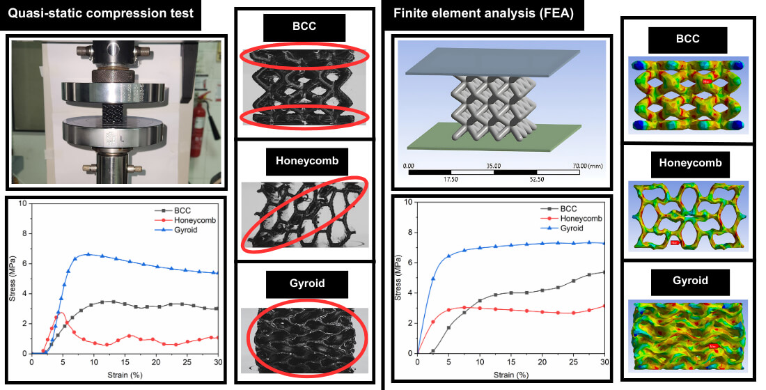
The compressive stress-strain behaviour of the three lattice structures which are BCC, honeycomb and gyroid, fabricated from PLA through FDM was experimentally evaluated under quasi-static loading conditions. The stress-strain curves shown in Fig. 7 revealed distinct deformation responses characteristic of each lattice topology. The gyroid structure exhibited a smooth and continuous curve with a prolonged plateau region, indicating progressive and uniform deformation facilitated by its continuous sheet-based architecture. These observations align with previous studies on lattice structures, where continuous topologies like gyroid tend to distribute stress more evenly, thereby delaying localized failure and enhancing energy absorption capacity [45]. In contrast, the honeycomb and BCC structures, being strut-based designs, displayed more pronounced fluctuations and multiple peaks in their curves, corresponding to sequential buckling and collapse of individual struts. This behaviour is consistent with past research, which showed that strut-based structures exhibit stress–strain curves with multiple peaks, indicating sequential structural instability and realignment during compression [46]. Additionally, it should be noted that the stress-strain curves in Fig. 7 exhibit a minor initial toe region up to approximately 2.5% strain before entering the linear elastic region. This behavior is attributed to initial settling and microstructural adjustments within the lattice structures, including localized pore collapse and realignment of struts under initial compressive loads, rather than testing setup compliance [8].

Figure 7: Compressive stress-strain curves obtained through experimental testing.
The mechanical properties derived from the compressive stress-strain curves revealed significant differences in performance among the three lattice structures based on Fig. 8. The gyroid structure consistently demonstrated better mechanical performance, achieving the highest values in all measured properties. It recorded an elastic modulus of 199.56 MPa, a yield strength of 5.37 MPa, a compressive strength of 6.64 MPa and a plateau strength of 5.58 MPa. In comparison, the honeycomb structure exhibited a 44% lower elastic modulus (111.98 MPa), a 53% reduction in yield strength (2.51 MPa), and a 60% decrease in compressive strength (2.66 MPa). Its plateau strength was the lowest among the three at 0.90 MPa, indicating a limited capacity for energy absorption after the initial yield point. Furthermore, the BCC lattice presented a more complex performance profile. While it recorded a lower elastic modulus (59.15 MPa) than the honeycomb, its strut-based design allowed for a higher compressive strength (3.31 MPa) and a significantly greater plateau strength (3.23 MPa) compared to the honeycomb, suggesting a more stable and gradual collapse mechanism. However, its yield strength (2.22 MPa) remained the lowest. The exceptional performance of the gyroid is attributed to its continuous, smooth and isotropic topology, which facilitates uniform stress distribution and minimizes stress concentration, thereby delaying the onset of failure and enabling higher energy absorption throughout the deformation process [47]. Conversely, the discrete strut-based designs of the BCC and honeycomb lattices are inherently prone to stress concentration at the nodes and struts, leading to earlier buckling and catastrophic failure, which ultimately limits their overall compressive resistance [48].

Figure 8: Mechanical properties under experimental testing in (a) Elastic modulus, (b) Yield strength, (c) Compressive strength and (d) Plateau strength.
3.2.2 Deformation Mechanism in Physical Test
Based on the visual analysis of the deformation progression captured during the physical compression tests, distinct and characteristic failure mechanisms were observed for each of the three lattice structures at the 30% strain mark, as highlighted in the red-circled regions in Fig. 9. The BCC lattice, a strut-based design, exhibited a non-uniform deformation pattern where the top and bottom regions of the structure underwent significant densification ahead of the central section. This behaviour is attributed to the sequential buckling and collapse of individual vertical struts, which initiated from the ends where platen contact stress concentrations were the highest, leading to a progressive layer-wise failure from the ends inward [49]. In contrast, the honeycomb lattice demonstrated a more localized failure mechanism, characterised by the formation of a distinct diagonal shear band across its structure. This shear band resulted from the coordinated buckling of its hexagonal cells, which aligned along a preferential plane of weakness under the compressive load, causing a sudden drop in load-bearing capacity and indicating a typical shear-dominated failure common in cellular structures with periodic but anisotropic designs [2]. Conversely, the gyroid lattice, with its continuous TPMS topology, displayed a remarkably uniform and homogeneous deformation throughout its entire volume without any visible localised shear bands or abrupt densification zones. The absence of stress-concentrating nodes and the presence of smoothly interconnected curved surfaces allowed for even stress distribution and a gradual layer-by-layer compaction, which is a hallmark of sheet-based architectures and contributes significantly to their better energy absorption efficiency [50]. These observed mechanisms align well with the stress-strain responses, where the gyroid’s smooth plateau contrasted with the fluctuating curves of the strut-based BCC and honeycomb, highlighting the critical influence of topological design on deformation behaviour and structural resilience under compressive loads.

Figure 9: Deformation behaviour under experimental testing in (a) BCC, (b) Honeycomb and (c) Gyroid structures.
The post-test SEM examination presented in Fig. 10 provided further microstructural insights into the deformation mechanisms. The BCC structure revealed catastrophic fracture at the nodal junctions, where stress concentration was most severe. The struts showed breaks with little evidence of plastic deformation, indicating that the failure was dominated by bending-induced fracture at the nodes, which aligns with the observed sequential collapse in the macroscopic analysis. This brittle fracture mode at the nodes further confirms that the nodal regions are the weakest points in the BCC structure. They act as critical stress risers that lead to sudden and catastrophic failure rather than gradual and progressive collapse. For the honeycomb structure, the SEM analysis confirmed the shear band observed in macroscopic level, showing a combination of strut buckling and layer delamination within the affected cells. The fracture surfaces indicated a mixed-mode failure, where the vertical struts buckled and the adhered layers separated due to the shear stresses, resulting in the sharp stress drops in its compressive stress-strain curve. The observed layer delamination further highlights the influence of the FDM process without support structures, where the interlayer bond strength was insufficient to withstand the shear forces. This is mainly because the honeycomb pattern creates a mid-span overhang during printing, thereby worsening shear-band failure. In contrast, the curved sheets of the gyroid structure showed more ductile-like crushing behaviour rather than sharp fractures. The absence of concentrated nodal failures across the sheet surfaces further indicated the overall homogeneous deformation, which was consistent with the macroscopic observation. Furthermore, the continuous and crumpled appearance of the gyroid sheet walls suggests a progressive and a layer-by-layer plastic collapse mechanism. This behaviour is attributed to the smooth and node-free topology, which prevents localized failure and allows the structure to collapse in a controlled manner. This mechanism effectively dissipates energy over a larger volume, which is a key factor leading to the gyroid’s greater compressive strength as shown in the mechanical properties analysis.

Figure 10: SEM images at 30% strain in (a) BCC, (b) Honeycomb and (c) Gyroid structures.
3.3.1 Mechanical Properties in Simulation Test
The FEA provided a numerical insight into the compressive mechanical properties of the BCC, honeycomb and gyroid lattice structures, providing stress-strain curves and quantitative data for direct comparison with experimental results. The simulated compressive stress-strain curves for the three lattices shown in Fig. 11 exhibited deformation trends that were fundamentally consistent with the experimental curves in Fig. 7. Both sets of curves demonstrated the characteristic deformation behaviour of lattice structures, which includes an initial linear elastic region and a prolonged plateau stress region indicative of progressive collapse [36]. The gyroid structure, in both simulation and experiment, displayed a notably smoother and more continuous curve with an extended plateau, reflecting its continuous sheet-based architecture that facilitates uniform stress distribution and gradual yielding. In contrast, the simulated curves for the strut-based BCC and honeycomb structures showed pronounced fluctuations and multiple peaks, mirroring the experimental observation of sequential buckling and collapse of individual struts. It is noted that the simulated stress-strain curve for the BCC structure does not begin at exactly zero strain. This offset is a result of the numerical contact in the explicit dynamics solver, which accounts for the initial settling of the structure under the compression plate before full engagement. However, a key difference between the simulated and experimental curves lay in the magnitude of the stress value. The FEA results predicted significantly higher stress levels across all strains. This discrepancy is attributed to the idealized conditions inherent in the simulation, which did not account for manufacturing defects such as micro-voids, layer adhesion inconsistencies and geometric inaccuracies that are unavoidable in physical FDM-produced samples and inherently reduce their load-bearing capacity [29].

Figure 11: Compressive stress-strain curves obtained through simulation testing.
The simulated mechanical properties presented in Fig. 12 demonstrated a strong correlation with the experimental trends from Fig. 8, consistently ranking the gyroid as the best performing structure, followed by the honeycomb and then the BCC structure, yet they exhibited notable differences attributable to the idealized nature of FEA. The simulation accurately captured the gyroid’s better performance, calculating an elastic modulus of 197.23 MPa, a yield strength of 5.10 MPa, a compressive strength of 6.98 MPa and a plateau strength of 7.29 MPa, which were all the highest among the three designs. The hierarchy was also maintained for the honeycomb lattice, with simulated values of 83.73 MPa (elastic modulus), 2.19 MPa (yield strength), 3.00 MPa (compressive strength) and 2.83 MPa (plateau strength). However, a key divergence occurred in the relative performance of the BCC and honeycomb structures. While the experiment showed the honeycomb’s elastic modulus (111.98 MPa) was 89% higher than the BCC (59.15 MPa), the simulation predicted a much smaller enhancement with the honeycomb (83.73 MPa) exhibiting only a 37% higher modulus than the BCC (61.28 MPa). Furthermore, the simulation predicted the BCC’s plateau strength (4.79 MPa) to be 69% higher than the honeycomb’s (2.83 MPa), a trend that was present but less pronounced in the physical test, where the BCC recorded 3.23 MPa and the honeycomb recorded 0.90 MPa. These quantitative discrepancies, where simulation often predicted higher strength values, stem from the FEA modelling a perfect geometry with homogeneous material properties and flawless nodal connections, unlike the physical samples which contained FDM-induced defects that act as stress concentrators and reduce overall load-bearing capacity [15]. The overestimation of the BCC’s performance, particularly its plateau strength, suggests the simulation did not fully capture the susceptibility of its slender struts to buckling failures initiated by real-world imperfections [51]. Despite these differences in value, the fundamental agreement in the performance hierarchy between simulation and experiment validates the FEA’s utility in predicting the mechanical performance of different lattice structures.

Figure 12: Mechanical properties under simulation testing in (a) Elastic modulus, (b) Yield strength, (c) Compressive strength and (d) Plateau strength.
3.3.2 Deformation Mechanism in Simulation Test
The deformation mechanisms of the BCC, honeycomb and gyroid lattice structures under compressive loading were further presented through FEA, with a particular focus on the von Mises stress distribution up to 30% strain as shown in Fig. 13. The von Mises stress contours revealed distinct failure patterns for each topology, which were consistent with their respective architectural characteristics. For the BCC lattice, stress concentrations were predominantly observed at the nodes and strut junctions, with maximum von Mises stress values reaching approximately 41 MPa. The deformation pattern indicated that the top and bottom regions of the structure underwent significant densification ahead of the central section. This simulation result aligns well with the physical deformation observed in Fig. 9a, where a non-uniform layer-wise collapse from the ends. In contrast, the honeycomb lattice exhibited stress concentrations primarily along the vertical struts and at the intersections of hexagonal cells, with peak von Mises stresses around 16 MPa. However, unlike the experimental results which showed a distinct diagonal shear band formation in Fig. 9b, the simulation did not capture this localized shear failure mechanism. This discrepancy is likely due to the idealized geometric and material conditions in the simulation, which did not account for manufacturing-induced defects such as layer adhesion inconsistencies or micro-voids that promote shear band initiation in physical samples [2]. The absence of this shear band in the simulation explains the observed differences in mechanical properties, such as the higher plateau strength in FEA compared to the experimental results, with a difference of 103%. Conversely, the gyroid lattice showed a uniform von Mises stress distribution throughout its structure, with no prominent stress concentrations and maximum values around 36 MPa. The continuous, smooth topology of the gyroid facilitated even stress distribution and homogeneous deformation, which was in excellent agreement with the experimental observations in Fig. 9c, where no localized failure or shear bands were evident. The consistent deformation behaviour across both simulation and experiment highlights the gyroid’s better structural resilience. Overall, the FEA successfully captured the fundamental deformation mechanisms for the BCC and gyroid structures, while highlighting the limitations of simulation tests in replicating failure modes such as shear banding in honeycomb structures. These findings emphasize the importance of incorporating material imperfections and anisotropy in future simulations to better predict the mechanical behaviour of additively manufactured lattice structures.

Figure 13: Von mises stress under simulation testing in (a) BCC, (b) Honeycomb and (c) Gyroid structures.
Based on the comprehensive experimental and simulation analysis conducted in this study, it can be concluded that the gyroid lattice structure fabricated from PLA via FDM exhibited better compressive performance, outperforming both the BCC and honeycomb structures with a 44% higher elastic modulus (199.56 MPa), 53% greater yield strength (5.37 MPa), and 60% increased compressive strength (6.64 MPa) compared to the honeycomb design. The continuous sheet-based architecture of the gyroid facilitated uniform stress distribution and homogeneous deformation, leading to enhanced energy absorption and structural resilience. The use of in-house extruded PLA filament represented a key methodological choice, ensuring consistent material properties across all specimens. This control over the raw material was fundamental for ensuring that the observed performance differences were due to lattice geometry, rather than variations in filament properties. Furthermore, the developed finite element models successfully captured the fundamental deformation trends and the mechanical performance across the three lattices, although some overestimation in mechanical properties was observed due to the idealized assumptions in the simulation that did not account for 3D-print defects. This research provides validated computational tools and practical insights for selecting and advancing lattice structures in sustainable lightweight applications, particularly in industries requiring energy-absorbing components. The integration of numerical and experimental approaches, based on controlled material input, establishes a robust framework that can be used in future studies to further explore the effects of material anisotropy and hybrid lattice designs on the mechanical behaviour of additively manufactured biodegradable polymers.
Acknowledgement: The authors acknowledge the support provided by the Faculty of Engineering and Built Environment & Centre for Research and Instrumentation Management (CRIM), Universiti Kebangsaan Malaysia, which facilitated access to critical resources, technical facilities and research activities essential to the completion of this study.
Funding Statement: This work was supported by the Fundamental Research Grant Scheme (FRGS), grant number FRGS/1/2024/TK10/UKM/02/3, funded by the Ministry of Higher Education (MOHE), Malaysia. Part of this research was supported by the Faculty of Engineering and Built Environment & Centre for Research and Instrumentation Management (CRIM), Universiti Kebangsaan Malaysia, through the grant number Dana Pecutan Penerbitan FKAB.
Author Contributions: Izzat bin Mat Samudin: Methodology, Investigation, Conceptualization, Writing—Original Draft, Writing—Review & Editing, Visualization; Muhammad Adam Johan bin Muhammad Affindy: Methodology, Investigation, Writing—Original Draft, Visualization; Quanjin Ma: Supervision; Nabilah Afiqah binti Mohd Radzuan: Validation, Writing—Review & Editing, Project Administration, Funding Acquisition, Supervision. All authors reviewed and approved the final version of the manuscript.
Availability of Data and Materials: The data that support the findings of this study are available from the corresponding author upon reasonable request.
Ethics Approval: Not applicable.
Conflicts of Interest: The authors declare no conflicts of interest.
Abbreviations
| AM | Additive manufacturing |
| BCC | Body-centered cubic |
| CAD | Computer-aided design |
| FEA | Finite element analysis |
| FDM | Fused deposition modelling |
| IWP | I-wrapped periodic |
| PLA | Polylactic acid |
| SC | Simple cubic |
| SEM | Scanning electron microscopy |
| STEP | Standard for the exchange of product model data |
| STL | Stereolithography |
| SDG | Sustainable development goals |
| TPMS | Triply periodic minimal surface |
References
1. Capasso I, Andreacola FR, Brando G. Additive manufacturing of metal materials for construction engineering: an overview on technologies and applications. Metals. 2024;14(9):1033. doi:10.3390/met14091033. [Google Scholar] [CrossRef]
2. Peng C, Marzocca P, Tran P. Triply periodic minimal surfaces based honeycomb structures with tuneable mechanical responses. Virtual Phys Prototyp. 2023;18(1):e2125879. doi:10.1080/17452759.2022.2125879. [Google Scholar] [CrossRef]
3. Radzuan NAM, Samudin IM, Al-Furjan M, Sulong AB, Foudzi FM, Azman MA. Thermal and mechanical properties of in-house-manufactured pla and pa filaments at high temperature. Mater Tehnol. 2025;59(4):611–20. doi:10.17222/mit.2024.1309. [Google Scholar] [CrossRef]
4. Wang M, Zhang J, Wang W. Compression and deformation behaviors of hierarchical circular-cell lattice structure with enhanced mechanical properties and energy absorption capacity. Aerospace. 2022;9(12):786. doi:10.3390/aerospace9120786. [Google Scholar] [CrossRef]
5. Bezek LB, Nakarmi S, Pantea AC, Leiding JA, Daphalapurkar NP, Lee KS. Effect of part size, displacement rate, and aging on compressive properties of elastomeric parts of different unit cell topologies formed by vat photopolymerization additive manufacturing. Polymers. 2024;16(22):3166. doi:10.3390/polym16223166. [Google Scholar] [PubMed] [CrossRef]
6. Libonati F, Graziosi S, Ballo F, Mognato M, Sala G. 3D-printed architected materials inspired by cubic bravais lattices. ACS Biomater Sci Eng. 2023;9(7):3935–44. doi:10.1021/acsbiomaterials.0c01708. [Google Scholar] [PubMed] [CrossRef]
7. Novak N, Al-Ketan O, Krstulović-Opara L, Rowshan R, Abu Al-Rub RK, Vesenjak M, et al. Quasi-static and dynamic compressive behaviour of sheet TPMS cellular structures. Compos Struct. 2021;266:113801. doi:10.1016/j.compstruct.2021.113801. [Google Scholar] [CrossRef]
8. Mat Samudin I, Mohd Radzuan NA, Sulong AB, Ma Q, Azman AH, Wan Zamri WFH. Stress strain curve analysis of sheet based TPMS structures in quasi static compression test: a review. J Mater Res Technol. 2025;36:5757–96. doi:10.1016/j.jmrt.2025.04.168. [Google Scholar] [CrossRef]
9. Nakarmi S, Kim J, Bezek LB, Leiding JA, Lee KS, Daphalapurkar NP. The role of unit cell topology in modulating the compaction response of additively manufactured cellular materials using simulations and validation experiments. Model Simul Mater Sci Eng. 2024;32(5):055029. doi:10.1088/1361-651X/ad472f. [Google Scholar] [CrossRef]
10. Zhang H, Zhao J, Niu Q, Xu C, Huo R. A study of energy absorption properties of Heteromorphic TPMS and Multi-morphology TPMS under quasi-static compression. Thin Walled Struct. 2024;205:112519. doi:10.1016/j.tws.2024.112519. [Google Scholar] [CrossRef]
11. Amirpour M, Battley M. Study of manufacturing defects on compressive deformation of 3D-printed polymeric lattices. Int J Adv Manuf Technol. 2022;122(5):2561–76. doi:10.1007/s00170-022-10062-0. [Google Scholar] [CrossRef]
12. Harris M, Potgieter J, Mohsin H, Chen JQ, Ray S, Arif KM. Partial polymer blend for fused filament fabrication with high thermal stability. Polymers. 2021;13(19):3353. doi:10.3390/polym13193353. [Google Scholar] [PubMed] [CrossRef]
13. Vasile A, Constantinescu DM, Indreş AI, Coropeţchi IC, Sorohan Ș., Apostol DA. Numerical simulation of compressive testing of sandwich structures with novel triply periodic minimal surface cores. Materials. 2025;18(2):260. doi:10.3390/ma18020260. [Google Scholar] [PubMed] [CrossRef]
14. Seharing A, Azman AH, Abdullah S. Finite element analysis of gradient lattice structure patterns for bone implant design. Int J Struct Integr. 2020;11(4):535–45. doi:10.1108/ijsi-03-2020-0028. [Google Scholar] [CrossRef]
15. Armillotta A, Bellotti M, Cavallaro M. Warpage of FDM parts: experimental tests and analytic model. Robot Comput Integr Manuf. 2018;50:140–52. doi:10.1016/j.rcim.2017.09.007. [Google Scholar] [CrossRef]
16. Wu H, Jiang C, Tang C, Wang L, Huang S, Ge S, et al. Binder jetting printed in situ mullite strengthened alumina ceramics with excellent mechanical and thermal properties through multi-phase infiltration. Virtual Phys Prototyp. 2024;19(1):e2427240. doi:10.1080/17452759.2024.2427240. [Google Scholar] [CrossRef]
17. Ramadneh M, Rashed MG, Fraser D, Chavara DT, Zinoviev A, Bhattacharyya D, et al. Ti6Al4V ELI microlattices produced by electron beam powder bed fusion: an investigation into the process-structure-property relationship across a wide range of strain rates. Mater Sci Eng A. 2025;941:148555. doi:10.1016/j.msea.2025.148555. [Google Scholar] [CrossRef]
18. Yang D, Guo L, Fan C. Mechanical behavior of 3D-printed thickness gradient honeycomb structures. Materials. 2024;17(12):2928. doi:10.3390/ma17122928. [Google Scholar] [PubMed] [CrossRef]
19. Zhang L, Lee W, Li X, Jiang Y, Fang NX, Dai G, et al. 3D direct printing of mechanical and biocompatible hydrogel meta-structures. Bioact Mater. 2021;10:48–55. doi:10.1016/j.bioactmat.2021.08.015. [Google Scholar] [PubMed] [CrossRef]
20. Ghaemi Khiavi S, Mohammad Sadeghi B, Divandari M. Effect of topology on strength and energy absorption of PA12 non-auxetic strut-based lattice structures. J Mater Res Technol. 2022;21:1595–613. doi:10.1016/j.jmrt.2022.09.116. [Google Scholar] [CrossRef]
21. Zhang Q, Wu W, Liu J. Local strengthening design and compressive behavior study of the triangular honeycomb structure. Metals. 2022;12(11):1779. doi:10.3390/met12111779. [Google Scholar] [CrossRef]
22. Lu J, Dong P, Zhao Y, Zhao Y, Zeng Y. 3D printing of TPMS structural ZnO ceramics with good mechanical properties. Ceram Int. 2021;47(9):12897–905. doi:10.1016/j.ceramint.2021.01.152. [Google Scholar] [CrossRef]
23. Liu W, Song H, Huang C. Maximizing mechanical properties and minimizing support material of PolyJet fabricated 3D lattice structures. Addit Manuf. 2020;35:101257. doi:10.1016/j.addma.2020.101257. [Google Scholar] [CrossRef]
24. Kaeonarong P, Tangtrakulwanich B, Petdee T, Yuenyongviwat V, Thongruang W, Srewaradachpisal S. Experimental study on the design and modeling of honeycomb structures for impact force attenuation in hip protectors. Ain Shams Eng J. 2026;17(2):103986. doi:10.1016/j.asej.2026.103986. [Google Scholar] [CrossRef]
25. Khan SA, Rahman MA, Khraisheh M, Hassan IG. Advances in 3D printed periodic lattice structures for energy research: energy storage, transport and conversion applications. Mater Des. 2024;239:112773. doi:10.1016/j.matdes.2024.112773. [Google Scholar] [CrossRef]
26. de Aquino DA, Maskery I, Longhitano GA, Jardini AL, del Conte EG. Investigation of load direction on the compressive strength of additively manufactured triply periodic minimal surface scaffolds. Int J Adv Manuf Technol. 2020;109(3):771–9. doi:10.1007/s00170-020-05706-y. [Google Scholar] [CrossRef]
27. Sankineni R, Kumar YR. Evaluation of energy absorption capabilities and mechanical properties in FDM printed PLA TPMS structures. Proc Inst Mech Eng Part C J Mech Eng Sci. 2022;236(7):3558–77. doi:10.1177/09544062211039530. [Google Scholar] [CrossRef]
28. Khalid NN, Mohd Radzuan NA, Sulong AB, Mohd Foudzi F, Hui D. Adhesion behaviour of 3D printed polyamide-carbon fibre composite filament. Rev Adv Mater Sci. 2022;61(1):838–48. doi:10.1515/rams-2022-0281. [Google Scholar] [CrossRef]
29. Radzuan NAM, Samudin IM, Sereshk MRV, Ma Q, Sulong AB, Foudzi FM, et al. A comprehensive approach for the production of carbon fibre-reinforced polylactic acid filaments with enhanced wear and mechanical behaviour. E Polym. 2025;25:20250002. doi:10.1515/epoly-2025-0002. [Google Scholar] [CrossRef]
30. Xu Z, La Mendola I, Razavi N, Bagherifard S. Additive manufactured Triply Periodical Minimal Surface lattice structures with modulated hybrid topology. Eng Struct. 2023;289:116249. doi:10.1016/j.engstruct.2023.116249. [Google Scholar] [CrossRef]
31. Khalid NN, Awang Adi FZ, Mohd Radzuan NA, Sulong AB. Shear test characterization of 3D printed polyamide reinforced carbon fiber composites. J Kejuruter. 2023;35(2):431–6. doi:10.17576/jkukm-2023-35(2)-14. [Google Scholar] [CrossRef]
32. Maskery I, Aremu AO, Parry L, Wildman RD, Tuck CJ, Ashcroft IA. Effective design and simulation of surface-based lattice structures featuring volume fraction and cell type grading. Mater Des. 2018;155:220–32. doi:10.1016/j.matdes.2018.05.058. [Google Scholar] [CrossRef]
33. Alagha AN, Sheikh-Ahmad JY, Almesmari A, Jarrar F, Almaskari F, Abu Al-Rub RK. Mechanical behavior and energy absorption of TPMS diamond structures and hybrid SC-FCC-BCC plate-lattices. J Eng Mech. 2024;150(12):04024088. doi:10.1061/jenmdt.emeng-7537. [Google Scholar] [CrossRef]
34. Qin D, Sang L, Zhang Z, Lai S, Zhao Y. Compression performance and deformation behavior of 3D-printed PLA-based lattice structures. Polymers. 2022;14(5):1062. doi:10.3390/polym14051062. [Google Scholar] [PubMed] [CrossRef]
35. Al-Ketan O, Lee DW, Rowshan R, Abu Al-Rub RK. Functionally graded and multi-morphology sheet TPMS lattices: design, manufacturing, and mechanical properties. J Mech Behav Biomed Mater. 2020;102:103520. doi:10.1016/j.jmbbm.2019.103520. [Google Scholar] [PubMed] [CrossRef]
36. Chen R, Wang S, Wu Z, Jia Y, Zhang W, Cao B, et al. Compressive enhancement gyroid lattice with implicit modeling implementation and modified G-a model property prediction. Mater Des. 2023;232:112153. doi:10.1016/j.matdes.2023.112153. [Google Scholar] [CrossRef]
37. Gao C, Shi J, Tang H, Tang H, Xiao Z, Bi Y, et al. Mechanical properties and energy absorption capabilities of plate-based AlSi10Mg metamaterials produced by laser powder bed fusion. J Mater Res Technol. 2024;30:3851–62. doi:10.1016/j.jmrt.2024.04.114. [Google Scholar] [CrossRef]
38. Shojaee M, Valizadeh I, Klein DK, Sharifi P, Weeger O. Multiscale modeling of functionally graded shell lattice metamaterials for additive manufacturing. Eng Comput. 2024;40(3):2019–36. doi:10.1007/s00366-023-01906-8. [Google Scholar] [CrossRef]
39. Elenskaya NV, Tashkinov MA, Silberschmidt VV. Numerical modeling of the deformation behavior of polymer lattice structures with a density gradient based on additive technologies. Vestnik StPetersb UnivMath. 2022;55(4):443–52. doi:10.1134/s1063454122040045. [Google Scholar] [CrossRef]
40. Bahrami Babamiri B, Askari H, Hazeli K. Deformation mechanisms and post-yielding behavior of additively manufactured lattice structures. Mater Des. 2020;188:108443. doi:10.1016/j.matdes.2019.108443. [Google Scholar] [CrossRef]
41. Széles L, Horváth R, Rádics JP. Design and study of fractal-inspired metamaterials with equal density made from a strong and tough thermoplastic. Polymers. 2023;15(12):2650. doi:10.3390/polym15122650. [Google Scholar] [PubMed] [CrossRef]
42. Zhang J, Chi M, Qian B, Qiu Z. Periodic lattice porous structure produced by selective Laser melting: process, experiment and numerical simulation analysis. Comput Model Eng Sci. 2020;125(1):77–94. doi:10.32604/cmes.2020.010518. [Google Scholar] [CrossRef]
43. Andrew JJ, Alhashmi H, Schiffer A, Kumar S, Deshpande VS. Energy absorption and self-sensing performance of 3D printed CF/PEEK cellular composites. Mater Des. 2021;208:109863. doi:10.1016/j.matdes.2021.109863. [Google Scholar] [CrossRef]
44. Zhang X, Zheng X, Han Y, Tian Y, Zhang D, Yan L. Failure mechanisms and process defects of 3D-printed continuous carbon fiber-reinforced composite circular honeycomb structures with different stacking directions. Aerosp Sci Technol. 2024;148:109075. doi:10.1016/j.ast.2024.109075. [Google Scholar] [CrossRef]
45. Cresswell ND, Ameri AAH, Wang J, Wang H, Hazell P, Escobedo-Diaz JP. Characterization and modelling of triply periodic minimum surface (TPMS) lattice structures for energy absorption in automotive applications. In: Characterization of minerals, metals, and materials. Cham, Switzerland: Springer; 2024. p. 295–305. doi:10.1007/978-3-031-50304-7_28. [Google Scholar] [CrossRef]
46. Lu Z, Yan W, Yan P, Yan B. A novel precipitate-type architected metamaterial strengthened via Orowan bypass-like mechanism. Appl Sci. 2020;10(21):7525. doi:10.3390/app10217525. [Google Scholar] [CrossRef]
47. Saleh M, Anwar S, Al-Ahmari AM, Alfaify A. Compression performance and failure analysis of 3D-printed carbon fiber/PLA composite TPMS lattice structures. Polymers. 2022;14(21):4595. doi:10.3390/polym14214595. [Google Scholar] [PubMed] [CrossRef]
48. Fadeel A, Mian A, Al Rifaie M, Srinivasan R. Effect of vertical strut arrangements on compression characteristics of 3D printed polymer lattice structures: experimental and computational study. J Mater Eng Perform. 2019;28(2):709–16. doi:10.1007/s11665-018-3810-z. [Google Scholar] [CrossRef]
49. Gao F, Zeng Q, Wang J, Liu Z, Liang J. Compressive properties and energy absorption of BCC lattice structures with bio-inspired gradient design. Acta Mech Sin. 2022;38(1):421345. doi:10.1007/s10409-021-09013-3. [Google Scholar] [CrossRef]
50. Ramos H, Santiago R, Soe S, Theobald P, Alves M. Response of gyroid lattice structures to impact loads. Int J Impact Eng. 2022;164:104202. doi:10.1016/j.ijimpeng.2022.104202. [Google Scholar] [CrossRef]
51. Seharing A, Azman AH, Abdullah S. A review on integration of lightweight gradient lattice structures in additive manufacturing parts. Adv Mech Eng. 2020;12(6):1687814020916951. doi:10.1177/1687814020916951. [Google Scholar] [CrossRef]
Cite This Article
 Copyright © 2026 The Author(s). Published by Tech Science Press.
This work is licensed under a Creative Commons Attribution 4.0 International License , which permits unrestricted use, distribution, and reproduction in any medium, provided the original work is properly cited.
 Downloads
 Citation Tools