
 Submit a Paper
 Propose a Special lssue
 Open Access
ARTICLE

Analytical Investigation into the Rotational Performance of Glulam Bolted Beam-Column Connections under Coupled Bending Moment and Shear Force
1
Department of Wooden Structure Construction, College of Materials Science and Engineering, Nanjing Forestry University,
Nanjing, China
2
Department of Civil Engineering, College of Civil Engineering and Architecture, Hainan University, Haikou, China
* Corresponding Author: Lisheng Luo. Email:
(This article belongs to the Special Issue: Advanced Wood Composites from Renewable Materials)
Journal of Renewable Materials 2023, 11(4), 2033-2054. https://doi.org/10.32604/jrm.2022.023651
Received 07 May 2022; Accepted 19 July 2022; Issue published 01 December 2022
 View Full Text
 Download PDF
Abstract
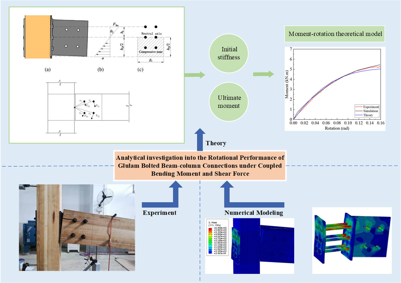
Considering the glulam beam-column connection form and the number of bolts, monotonic loading test and finite element analysis was carried out on 9 connection specimens in 3 groups to study the rotational performance and failure mode of the connection. The test results revealed that compared with U-shaped connectors, T-shaped connectors can effectively improve the ductility of connections, and the increase in the number of bolts can reduce the initial stiffness and ductility of connections. By theoretical analysis, formulas for calculating the initial stiffness and ultimate moment of connections were deduced. Subsequently, the moment-rotation theoretical model of connections was established based on the formulas, which were validated according to the test data and simulation results. The proposed model can not only improve the current theoretical system of heavy-duty glulam beam-column structure but also provide a theoretical basis for calculating the mechanical properties of the glulam beam-column connection.Graphic Abstract
Keywords
The heavy-duty glulam beam-column connection is usually inferior to timber structure itself in strength, thereby leading to brittle failure of the connection [1,2]. Thus, the safety of glulam beam-column structure mainly depends on the bearing capacity of connections in timber structures. Connections in glulam beam-column structure are generally connected by steel plates and bolts [3–5]. The bolted connections characterized by clear force transmission and easy installation [6] have some moment-resisting capacities. As such, the connections can bear bending moment to a certain extent, showing the characteristics of semi-rigid connections [7–9].
So far, scholars all over the world have done a lot of work on the bolted glulam beam-column connection. Lam et al. [10] conducted monotonic and cyclic loading tests on T-shaped bolted beam-column connections with slotted steel plates. The test results showed that there exists dowel bearing pressure and splitting perpendicular to the grain when the connections fail. Shu et al. [11] conducted a comprehensive study on the rotational performance of bolted connections with slotted steel plates and put forward the formulas for calculating the bearing capacity and initial stiffness of connections. Wang et al. [12] focused on studying the combined action of bending moment and shear force caused by semi-rigid connections. The results revealed that with the increase in shear-moment ratio, the additional bending moment of connections decreases and the shear capacity increases. Li et al. [13], based on the above research, studied the rotational performance of bolted glulam beam-column connections with slotted steel plates under the combined action of bending moment and shear force by monotonic loading test, and proposed a theoretical calculation method for connection bearing capacity, providing the basis for connection design. Zhang et al. [14] studied the impact of cracks on the performance of bolted connections. It is found that initial cracks will not only reduce the flexural bearing capacity and initial stiffness of connections but also affect the ductility of connections.
Based on the existing research, three different forms of glulam beam-column connections were designed, and theoretical formulas of the initial stiffness and ultimate moment of connections were put forward. Additionally, the moment-rotation theoretical model of connections was established based on the formulas. The proposed theoretical model can not only improve the current theoretical system of heavy-duty glulam beam-column structure but also provide a theoretical basis for calculating the mechanical properties of the glulam beam-column connection.
The test involves three different materials, that is, glulam, steel, and bolts. For steel plates, the thickness is 6 mm, the strength grade is Q235B, the yield strength is 235 MPa, and the elastic modulus is 2.06 × 10⁶ MPa. For bolts, the diameter is 10 mm, the grade is 8.8, the yield strength is 640 MPa, and the elastic modulus is 2.06 × 10⁶ MPa. The glulam is made of Larix dahurica, which is the raw material, with a material class of IIa. In order to determine the mechanical property parameters of the timber, the mechanical property tests were conducted on timbers according to GB/T 1928-2009 [15], GB/T 1935-2009 [16] GB/T 15777-2017 [17], GB/T 1939-2009 [18] and ASTM D5764-97a [19]. The average values of this batch of Larix dahurica are as follows, the density is 670 kg/m³, the moisture content is 11.23%, the compressive strength parallel to the grain is 55.34 MPa, and the elastic modulus parallel to the grain is 12692.10 MPa. Additionally, the compressive strength perpendicular to the grain is 7.94 MPa, and the local compressive strength perpendicular to the grain is 9.80 MPa. Grade 8.8 bolts with a nominal diameter of 10 mm were adopted in the test, with the embedment strength parallel and perpendicular to the grain are 39.29 and 25.29 MPa, respectively.
The glulam beam with a cross sectional dimension of 100 mm (width) × 150 mm (depth) × 1000 mm (length). The glulam column was adopted as column member, with a cross sectional dimension of 100 mm × 100 mm × 1200 mm (depth).
Three groups, a total of 9 glulam beam-column connections, were designed for the test, which was numbered JM1, JM2, and JM3 in succession. For specimen parameters and specific structures, please refer to Table 1 and Fig. 1 in detail. Column members were connected to the beam ends through outer steel plates and connectors. The bolts crossed the beam and column members to enhance the mechanical performance of connections. The ends of the bolts connecting the beams and columns were embedded at the beam ends. Before the assembly of specimens, round holes were drilled at the beam ends in advance, with a diameter of 20 mm and a depth of 10 mm.


Figure 1: Details of connection specimens (Unit: mm)
The test device is composed of an outer counterforce frame, support structure, adjustment structure, load sensor, and jack. To prevent the column members from slipping and twisting in the loading process, the upper and lower ends of column members were fixed by loading connectors of the support structure. The jack connected to the load sensor was placed at the upper end of the beam member, which could not only reduce the preparations for test but also improve the test efficiency. The test loading diagram is shown in Fig. 2.
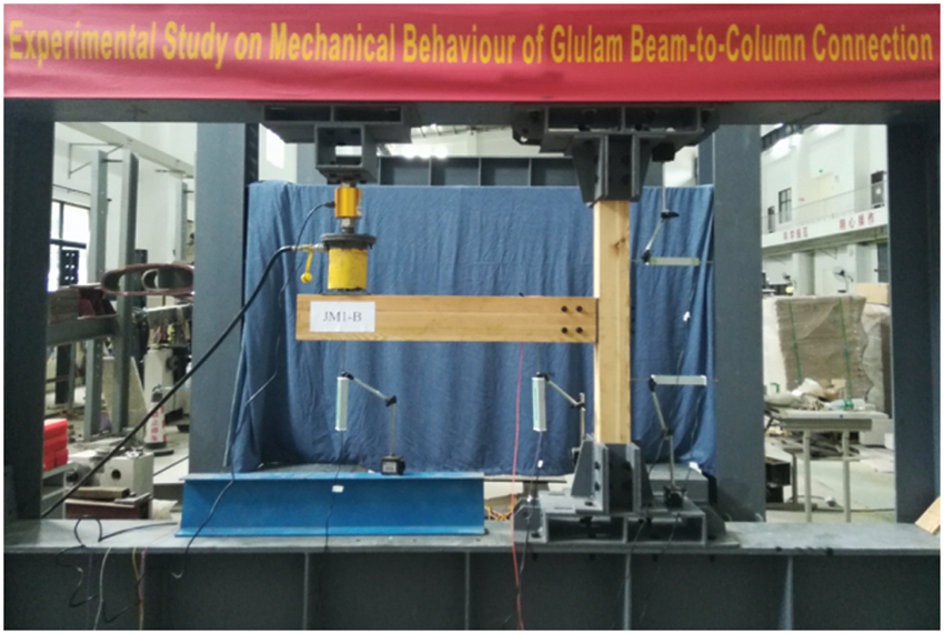
Figure 2: Test loading diagram
According to the American test standard ASTM D1761-20 [20], the unidirectional uniform displacement control loading method was employed in this test to apply a vertical load to the specimens in two stages:
(1) Preloading: apply a load to the beam end of the connection at a speed of 2 mm/min to 10% of the estimated ultimate bearing capacity, and unload after maintaining the load for about 2 min, to ensure the good contact of various members of the connection and the normal use of the test device;
(2) Formal loading: set the loading speed at the formal loading stage as 5 mm/min, and apply the load continuously until the connection obviously fails or the load drops to about 80% of the ultimate bearing capacity.
In an attempt to accurately measure the rotation angle between the beam and column, 4 LVDTs (linear voltage displacement transducers), i.e., T1–T4, were arranged on the specimen, as shown in Fig. 3. T1 and T2 were used to measure the vertical displacement of the beam, while T3 and T4 were to measure the horizontal displacement of the column. With the center of the side plate edge of the connector as the rotation center of the connection, the bending moment and rotation angle of the specimen can be calculated based on the data measured by the load sensor and LVDTs. The calculation formulas are as follows:

Figure 3: Layout of measuring points (Unit: mm)
where, F is the concentrated load; H is the distance between the side plate edge of the connector and T4 before test; H is the distance between T1 and T2 before test; Δn is the value of displacement measured by LVDT Tn.
At the initial loading stage, the specimen was at the elastic stage, and the test phenomena of each group of connections were basically the same, without obvious deformation. While the load was applied continuously, the rotation angle of the specimen became increasingly larger, and the bending moment in panel zone also increased gradually. The upper part of the contact surface between the connector side plate and the column was in tension and the lower part was compressed. Thus, the contact surface on the tension side gradually spread out, while the column on the compression side was visibly depressed and deformed due to local compression, with a slight hiss. With the continuous increase in rotation angle, the moment-rotation curve of the specimen entered the elastic-plastic stage. The contact surface on the tension side between the connector side plate and the column was separated by tension. The fiber of the column was cut off at the bottom on the compression side of the connector side plate and embedded in the column. The upper bolt in the column was stretched, and the timber began to deform plastically. There were slight differences in test phenomena of each group. At this stage, specimen JM1-C made a crisp timber cracking sound, and it could be observed that there were horizontal cracks in the lower part of the bolt hole on the compression side of the beam, as shown in Fig. 4, while the specimens JM2-A and JM3-C were free from cracks, as shown in Fig. 5. At the later loading stage, the failure modes of specimens were different. Cracks of the specimen JM1-C extended in parallel to the grain of the beam, and the bolts around the bolt hole of the beam were obviously deformed under pressure. The connector side plates of specimens JM2-A and JM3-C were embedded in the columns to a greater extent, the crushing range was gradually enlarged, and the bolts around the bolt hole of the beam were less deformed under pressure. Taking the specimen JM1-A as an example, after various members of the connection were disassembled, it was found that the upper bolt in the beam was more deformed than the lower bolt, and the plastic hinge of bolt 1 could be obviously observed. It is because the rotation center of the connection moves down due to bending deformation of the bolts in the loading process of the connection, and there is a longer distance between the upper bolt and the rotation center.

Figure 4: Test phenomena of T-shaped connections (a) Splitting perpendicular to the grain of the beam of JM1-C (b) Dowel bearing of the beam of JM1-A (c) Bolt deformation of the beam of JM1-A

Figure 5: Test phenomena of U-shaped connections (a) Bending deformation of the connector of JM2-A (b) Local crushing of the column of JM3-C (c) Bolt deformation of JM2-A
Moment-rotation curve is an important basis for measuring the performance of connections and is based on the test data, as shown in Fig. 6. The curve goes through three stages, i.e., elastic, elastic-plastic, and failure stages. As there is a certain initial gap between the bolt hole and the bolt, at the initial loading stage, the performance of connections is mainly related to the gap between the bolt hole and the bolt, and the stiffness is nonlinear. As the load increases gradually, the bolt hole and the bolt are in stable contact, the connection enters the linearly elastic stage, and the load transfer path is gradually clear.

Figure 6: Moment-rotation curve
It can be seen through analysis of the load transfer path that when a vertical load is applied to the beam end of the specimen, the load is mainly transferred from bolts in the beam to the connector, and the connector continuously transferred the load to bolts in the column and the wooden column. Additionally, the stiffness is basically stable and approximately constant. When the load increases to a certain extent, the curve shows nonlinear growth, and the connection enters the elastic-plastic stage. At this stage, plastic deformation of the glulam begins and develops continuously, and the connector and bolts are obviously deformed. The connector edge on the compression side is embedded in the column, and the connection stiffness decreases continuously. When the curve reaches the extreme point, it plummets and the connection fails.
Mechanical properties of the connection are mainly analyzed and evaluated based on initial stiffness K, yield moment My, yield angle θy, ultimate moment Mu, ultimate angle θu, failure moment Mf and failure angle θf of the connection. As the connection stiffness was always changing, only initial stiffness at the elastic stage was adopted for comparison. The initial stiffness of the connection was calculated as follows,
where, M40% and M10% are the bending moments corresponding to 40% and 10% of the ultimate moment Mu respectively. θ40% and θ10% are the rotation angles corresponding to M40% and M10%, respectively.
As there is no obvious demarcation point in the moment-rotation curve, it is difficult to determine the yield point. Liu et al. [21] compared 5 methods for defining the yield point and ductility and found that CSIRO [22] method could be used to accurately define the yield point and ductility degree of bolted connections in timber structures. The yield point under the CSIRO method is defined as the point with a rotation angle of 1.25 θ40% on the moment-rotation curve, as shown in Fig. 7.

Figure 7: CSIRO method for defining the yield point
According to the moment-rotation curve of the connection, the mechanical property data obtained in connection test are shown in Table 2.

As can be seen from the above table, the initial stiffness of connections in group JM1 approaches that of connections in group JM2. But the ductility of connections in group JM2 decreases by 11.7% and the ultimate moment increases by 4.15% compared with the parameters of connections in group JM1. It can be considered that the two connection forms have little influence on the initial stiffness and ultimate moment of connections, but the ductility of T-shaped connections is obviously better than that of U-shaped connections. Moreover, the initial stiffness of connections in group JM3 decreases by 5.53%, the ductility is reduces by 6.17%. With the increase in the number of bolts, both the initial stiffness and ductility of connections will decrease accordingly, but the change of ultimate moment is not obvious.
The rotation angle of the glulam beam-column connection studied in this paper is composed of the following components:
where, θ1 is the rotation angle of the column midpoint caused by bending deformation of the column; θ2 is the rotation angle of the contact surface between the connector side plate and the column; θ3 is the rotation angle caused by deformation of the connector; θ4 is the rotation angle of the contact surface between the beam end and the connector side plate.
According to Eq. (3), the rotational stiffness corresponding to the above rotation angles is in series. Thus, the rotational stiffness of connection is associated with each other as follows:
where, Keq is the overall equivalent rotational stiffness of the connection; K1 is the rotational stiffness of the column midpoint caused by bending deformation of the column; K2 is the rotational stiffness of the contact surface between the connector side plate and the column; K3 is the rotational stiffness of the connector; K4 is the rotational stiffness of the contact surface between the beam end and the connector side plate;
(1) Rotation angle and rotational stiffness of the column midpoint caused by bending deformation of the column.
The mechanical calculation diagram of the connection is shown in Fig. 8. The bending moment diagram of the column under actual load and unit virtual load is shown in Fig. 9.

Figure 8: Mechanical calculation

Figure 9: Bending moment diagram of the diagram of the connection column under actual load and unit virtual load
According to the diagram multiplication of structural mechanics, the rotation angle and rotational stiffness of the column midpoint caused by the bending deformation of the column are as follows:
where, M is the bending moment of the connection generated by actual loading force F of the beam, and
(2) Rotation angle and rotational stiffness of the contact surface between the connector side plate and the column.
The following assumptions are made for the calculation of the contact surface between the connector side plate and the column under the action of bending moment:
I The neutral axis of the contact surface between the connector side plate and the column is in tension on the upper side, the side plate is separated from the column, and the separation distance is proportional to the distance from the neutral axis;
II The neutral axis of the contact surface between the connector side plate and the column is compressed on the lower side, the side plate is in close contact with the glulam column, and the embedding degree is proportional to the distance from the neutral axis.
According to the above assumptions, the calculation diagram of the contact surface between the side plate of the T-shaped connector and the column is shown in Fig. 10.

Figure 10: Calculation diagram of the contact surface between the side plate of the T-shaped connector and the column (a) Side view of the connection deformation (b) Internal force diagram (c) Front view of the compressive zone
For the calculation of the rotation angle of the contact surface between the connector side plate and the column, the bolt is axially deformed under force, and there exists a rotation angle of the side plate, leading to local compressive stress at the contact surface of the column in the compressive zone. Therefore, the axial deformation of the bolt is an important factor in the rotation angle of the side plate. According to EC3 [23], the axial tensile stiffness of the bolt can be obtained as follows:
where, Kbo is the axial tensile stiffness of the bolt, and 0.8 is the impact factor with consideration of the prying force. Ebo is the elastic modulus of the bolts, Abo is the effective cross sectional area of the bolt in tension, and Lbo is the effective crossing length of the bolt.
When both the tensile stress of the bolt and the maximum compressive stress perpendicular to the grain is lower than the yield stress,
where, Fbo is the tensile force on the topmost bolt, Bc is the width of the connector side plate and hD is the height of the connector side plate. σ is the maximum compressive stress on the column, and h1 is the vertical distance from the topmost bolt to the midpoint of the side plate.
The following relational expression can be deduced from Eq. (8):
The rotation angle and rotational stiffness of the contact surface between the side plate and the column can be obtained by the transformation of Eq. (9):
(3) Rotation angle and rotational stiffness caused by deformation of the connector.
Based on Eq. (9), the relation between the bending moment M of the connection and the tensile force Fbo of the bolt can be deduced as follows:
I For T-shaped connectors, the strip plate between the topmost two bolts of the connector side plate is simplified as a simple supported beam. The width of the simple supported beam is the size of the bolt hole, and the tensile force borne by each bolt is the reaction force of the simple support. As such, the tensile force on the filler plate of the T-shaped connecting plate is 2Fbo, and the deflection deformation in the midspan of the simple supported beam is:
where, Es is the elastic modulus of the steel, and d is the size of the bolt hole, that is, the width of the simple supported beam. t is the thickness of the connector side plate, and Le is the horizontal distance between the topmost two bolts of the connector side plate.
According to the relation between the deflection and rotation angle, the rotation angle and rotational stiffness caused by the deformation of the T-shaped connector can be acquired:
II For U-shaped connectors, the strip plate from the topmost bolts of the side plate of the U-shaped connector to the outer edge is simplified as a cantilever beam. Then the deflection deformation at the end of the cantilever beam is:
The rotation angle and rotational stiffness caused by deformation of the U-shaped connector are obtained as follows:
(4) Rotation angle and rotational stiffness of the contact surface between the beam end and the connector side plate.
The bolts bear shear force under the action of torque, based on which the assumptions are made as follows:
I The filler plate of the connector is absolutely rigid, and the bolt is elastic;
II The connector rotates around the edge center of the side plate, and the shear force on each bolt is proportional to the distance ri from the bolt to the centroid, and its direction is perpendicular to the connecting line ri.
The calculation diagram of the end beam and the connector is shown in Fig. 11.
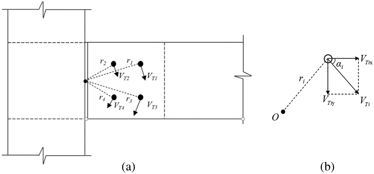
Figure 11: Calculation diagram of the end beam and the connector (a) Side view of the connection deformation (b) Force decomposition diagram of a single bolt
Based on the above assumptions, the following relation can be obtained:
where, VTi is the shear force of the ith bolt caused by torque, and ri is the distance from the ith bolt to the centroid.
The relation between torque M and the shear force is further deduced from Eq. (19), as shown below:
Eq. (20) can be further transformed as follows:
where, Ki is the slip modulus, and Δi is the slippage between the bolt and bolt hole.
Further, the following relational expression can be acquired:
According to the European Standard EN 1995-1-1 [24], the impact of moisture content is taken into account, and the formula for calculating the slip modulus of the connection is provided as follows:
where, Kdef = 0.6 is the moisture content parameter and Kser is the slip modulus.
The slip modulus Kser1 of the single shear surface of each bolt can be calculated by the following formula [25,26]:
where, ρ is the wood density. u1 and μ2 are regression coefficients, in which u1 = 1.5 and μ2 = 23 as stipulated in European Standard EN 1995-1-1.
Connections in this paper are double shear connections, and the formula for calculating the slip modulus Kser of each bolt is as follows:
By substituting Eq. (25) into Eq. (22), the rotation angle and rotational stiffness of the contact surface between the beam end and the connector side plate can be worked out as follows:
The failure modes of T-shaped and U-shaped connections are the bearing failure of dowels around the bolt hole of the beam and the bearing failure of the column in panel zone. The ultimate moments of connections corresponding to the two failure models are deduced respectively as follows:
(1) Bearing failure of dowels around bolt hole of the beam.
Bolts of the connector filler plate and the beam bear the shear force caused by vertical load and torque at the same time. The resultant shear force on each bolt is as follows:
where, VTix is the horizontal component of shear force caused by torque and borne by the ith bolt, while VTiy is the vertical component. VFi is the vertical force caused by vertical loading force and borne by the ith bolt and αi is the angle between the perpendicular line of the connecting line from the ith bolt to the centroid and the vertical direction.
The resultant shear force caused by torque available from Eq. (32) is as follows:
The formula for calculating the vertical force VFi caused by the vertical load F is as follows:
where, F is the vertical load borne by the beam, and n is the number of bolts of the beam.
As can be seen from Eq. (32), the direction of resultant shear force on the bolt is not uniquely determined, while the shear failure of the bolts of beam is related to the bearing strength of the beam, and the bearing strength is associated with the diagonal angle. The embedment strength at the diagonal angle of θ1 can be calculated according to the European standard EN 1995-1-1:
where, fe0 is the embedment strength parallel to the grain of the beam, fe90 is the embedment strength perpendicular to the grain of the beam, and feθ1 is the embedment strength at the diagonal angle of θ1.
According to the European standard EN 1995-1-1, the standard value Fk of the bearing capacity of single shear surface of the T-shaped connections at the diagonal angle of θ1 can be calculated by the following formulas:
where, Fk,Is, Fk,IIIs and Fk,IV are standard values of the bearing capacity of single shear surface under yield modes Is, IIIs and IV, respectively. T is the thickness of single shear surface of the beam. My,b is the flexural yield moment of bolts of the beam, and fu is the ultimate tensile strength of bolts of the beam.
(2) Bearing failure of the column in panel zone.
The ideal elastic-plastic constitutive model is generally adopted for the stress-strain relation between the timber and the steel. As can be seen from the calculation diagram in Fig. 12, when the maximum compressive stress of the contact surface between the connector side plate and the column exceeds the compressive yield strength perpendicular to the grain of the timber, there is a relation between the bolt force and the bending moment of the connection, as shown below:

Figure 12: Calculation diagram of stress change of the contact surface between connector side plate and the column
where, η is the compressive yield altitude coefficient perpendicular to the grain in panel zone of the column, which is between 0 and 1.
When η, the compressive yield altitude coefficient perpendicular to the grain in panel zone of the column, is set as 1, and the tensile stress of the bolt in tension is lower than the yield stress of the bolt, that is, the bolt in tension has not yet yielded, the column in panel zone reaches the ultimate state, and the ultimate moment can be calculated by Eq. (39) as follows:
4.3 Moment-Rotation Theoretical Model
Yee et al. [27] established a four-parameter exponential model of the relation between the bending moment and rotation angle of the bolted semi-rigid connection. The formula of the said model is as follows:
where, Mp is the plastic flexural capacity, K is the initial stiffness, Kp is the strain hardening stiffness, and c is a shape parameter.
Based on the assumptions and ignoring the strain hardening stage of the steel, the above parameter model can be simplified to a three-parameter exponential model [28]:
The three-parameter exponential model is of four characteristics, as shown below:
(1) When
(2) When
(3) When
(4) When
In Eq. (42), c is a shape parameter, and its specific value can be determined by test data regression.
The finite element model of connection is established based on Abaqus software. The connection consists of four parts, i.e., glulam beam and column, connector, outer steel plate, and bolt. Numerical models are all established based on the actual dimensions, with unified units. To ensure the accuracy of model materials, the connection is partitioned, including four parts, namely, timber outside dowel bearing area, timber in dowel bearing area, bolts, and steel plates, as shown in Fig. 13.

Figure 13: Partitioning schematic diagram of finite element model materials
Timber is a heterogeneous material, and the reasonable definition of timber properties is the basis of finite element model calculation. When defining the timber properties, the defects of the material itself are ignored, and it is simplified as an elastic-plastic anisotropic material under compression. Please refer to Table 3 [29] for material performance parameters. Existing studies show [30] that pre-drilling of the timber will cause damage to the timber in surrounding areas, causing the elastic modulus and stiffness of the timber in surrounding areas to be far lower than those of the timber in other areas. In view of the impact of the said damage, Hong [31] put forward a dowel bearing model reducing the area around the bolt hole. Due to the small edge distance of the bolt of test connection, there will be a great number of irregular elements in network partitioning proposed by Hong, which will affect the calculation results. To ensure the convergence and accuracy of the model, the dowel bearing area is set as a square with a side length of 40 mm, as shown in Fig. 13. Please refer to Table 4 for the specific parameters of mechanical properties of the timber in dowel bearing area.


Structured mesh is adopted to divide the parts that have been cut into regular geometric shapes in each component, while swept mesh is employed for the parts that cannot be cut into regular shapes. All elements are hexahedral elements C3D8R. In addition, the interactions among various components are defined by setting the contact relation. Please refer to Table 5 for the specific contact relation. Boundary conditions are subject to the actual test conditions, and both upper and lower ends of the column are fixed and constrained, that is, all degrees of freedom in three directions is restricted. As the displacement control mode is adopted in the connection test, the same loading mode should also be applied in the model, namely, setting a reference point at the center of loading surface, and achieving the control of loading surface by controlling the displacement of the said reference point. Meanwhile, to avoid rigid displacement of connections, the displacement and rotation of connectors along the bolt length direction of the beam shall still be constrained.

5.2 Simulation Results and Analysis
Specimens in group JM1 are taken as an example, and the corresponding stress contour is as shown in Fig. 14. It can be observed from the figure that the stress on glulam beam-column members is small, and the stress on the connector spreads out from the bolt hole. The parts with the maximum stress on bolts are all connected to connectors, that is, the middle part of the bolt in beam bears the maximum stress, and a plastic hinge is formed. However, the part with the maximum stress on the bolt in column is on the right side of the bolt, but the bolt is free from obvious bending deformation, which is consistent with the phenomena of bolt in the test. Moreover, the edge of the connector side plate on the compression side is embedded in the wooden column, and the bolt at the bottom of the column is slightly pushed out, which is consistent with the test phenomena.

Figure 14: Stress distribution of Group JM1
The test values, theoretical values, and simulation values of the ultimate moment and initial stiffness of all connection specimens are listed in Table 6. As can be seen from the table, the difference between the test value and theoretical value of initial stiffness is −3.50%~19.52%, and the difference between the test value and simulation value is −14.21%~0.90%. Additionally, the difference between the test value and theoretical value of the ultimate moment is 2.09%~19.52%, and the difference between the test value and simulation value is −1.88%~3.47%. The above differences are all within the reasonable range.

The test curve, theoretical curve, and simulation curve of specimens are shown in Fig. 15. As can be seen from Fig. 15, there is a big difference between theoretical and simulation values and the test values of initial stiffness. It is mainly because the timber adopted in test has different properties, while the timber used for theoretical analysis and numerical simulation is an ideal anisotropic material, ignoring the impact of its defects. On the whole, the test curve, theoretical curve, and simulation curve of each group of specimens are in good agreement. Therefore, the proposed method for calculating the initial stiffness and ultimate moment of connections in this paper is feasible.


Figure 15: Moment-rotation comparison curve
In this paper, the monotonic loading test is conducted on 3 groups of glulam beam-column connections, a total of 9 connections, with the number of bolts and connection forms as variables, to systematically study various properties of connections under the combined action of bending moment and shear force. The conclusions are mainly drawn as follows:
(1) The moment-rotation curve of connection specimens can be roughly divided into three stages, i.e., elastic stage, elastic-plastic stage and failure stage. At the initial loading stage, the connection enters the linearly elastic stage; the stiffness is basically stable and approximately constant. When the load increases to a certain extent, the curve shows nonlinear growth, and the connection enters the elastic-plastic stage. At this stage, plastic deformation of the glulam begins and develops continuously, and the connector and bolts are obviously deformed. The connector edge on the compression side is embedded in the column, and the connection stiffness decreases continuously. When the curve reaches the extreme point, it plummets and the connection fails.
(2) For connections of the same form, with the increase in the number of bolts, the initial rotational stiffness and ductility of connections decrease by 5.53% and 6.17%, respectively. With the same number of bolts, the change of connection form has little influence on the initial rotational stiffness of connections. However, the ductility of U-shaped connections decreases by 11.7% and the ultimate moment increases by 4.15% compared with the parameters of T-shaped connections.
(3) In this paper, based on the theories of material mechanics and structural mechanics, the calculation methods of initial stiffness and ultimate moment of connections and the theoretical model of moment-rotation are proposed. It is found that the theoretical results are consistent with the test results and numerical simulation results, which further validates the correctness of the theories proposed in this paper.
Funding Statement: The authors would like to acknowledge the support from a project funded by the National First-class Disciplines (PNFD), High Level Natural Science Foundation of Hainan Province of China (Grant No. 2019RC055) and Project Supported by the Education Department of Hainan Province (Project No. hnjg2021-13).
Conflicts of Interest: The authors declare that they have no conflicts of interest to report regarding the present study.
References
1. Vavrusova, K., Lokaj, A., Mikolasek, D., Sucharda, O. (2020). Analysis of longitudinal timber beam joints loaded with simple bending. Sustainability, 12(21), 9288. DOI 10.3390/su12219288. [Google Scholar] [CrossRef]
2. Poletti, E., Vasconcelos, G., Branco, J. M., Isopescu, B. (2019). Effects of extreme environmental exposure conditions on the mechanical behaviour of traditional carpentry joints. Construction and Building Materials, 213(1), 61–78. DOI 10.1016/j.conbuildmat.2019.04.030. [Google Scholar] [CrossRef]
3. Dobes, P., Lokaj, A., Mikolasek, D. (2022). Load-carrying capacity of double-shear bolted connections with slotted-in steel plates in squared and round timber based on the experimental testing, European yield model, and linear elastic fracture mechanics. Materials, 15(8), 2720. DOI 10.3390/ma15082720. [Google Scholar] [CrossRef]
4. Zhang, J., Yi, J., Xu, Y., Zhang, M. L. (2022). Cyclic response of moment-resisting glulam hybrid joints with bolts and side steel plates. Journal of Building Engineering, 51(3), 104310. DOI 10.1016/j.jobe.2022.104310. [Google Scholar] [CrossRef]
5. Shu, Z., Li, Z., He, M. J., Chen, F., Hu, C. (2020). Bolted joints for small and medium reticulated timber domes: Experimental study, numerical simulation, and design strength estimation. Archives of Civil and Mechanical Engineering, 20(3), 73. DOI 10.1007/s43452-020-00073-7. [Google Scholar] [CrossRef]
6. Liu, Y. Y., Wang, Y. X., Zhang, Y. M., Chen, M. H., Nie, X. Z. (2020). Force-displacement relations of bolted timber joints with slotted-in steel plates parallel to the grain. Journal of Wood Science, 66(1), 83. DOI 10.1186/s10086-020-01931-x. [Google Scholar] [CrossRef]
7. Karagiannis, V., Málaga-Chuquitaype, C., Elghazouli, A. Y. (2017). Behaviour of hybrid timber beam-to-tubular steel column moment connections. Engineering Structures, 131(3), 243–263. DOI 10.1016/j.engstruct.2016.11.006. [Google Scholar] [CrossRef]
8. Liu, Y. Y., Xiong, H. B. (2018). Lateral performance of a semi-rigid timber frame structure: Theoretical analysis and experimental study. Journal of Wood Science, 64(5), 591–600. DOI 10.1007/s10086-018-1727-7. [Google Scholar] [CrossRef]
9. Wang, M. Q., Gu, X. L., Song, X. B., Wu, Y. J. (2016). Experimental study on bolted glued laminated timber connections with slotted-in steel plates under pure bending and combined shear and bending. Journal of Building Structures, 37(4), 64–72. [Google Scholar]
10. Lam, F., Schulte-Wrede, M., Yao, C. C., Gu, J. J. (2008). Moment resistance of bolted timber connections with perpendicular to grain reinforcements. 10th World Conference on Timber Engineering, Miyazaki, Japan. [Google Scholar]
11. Shu, Z., Li, Z., Yu, X. S., Zhang, J., He, M. J. (2019). Rotational performance of glulam bolted joints: Experimental investigation and analytical approach. Construction and Building Materials, 213(10), 675–695. DOI 10.1016/j.conbuildmat.2019.03.002. [Google Scholar] [CrossRef]
12. Wang, M. Q., Song, X. B., Gu, X. L., Tang, J. Y. (2019). Bolted glulam beam-column connections under different combinations of shear and bending. Engineering Structures, 181(10), 281–292. DOI 10.1016/j.engstruct.2018.12.024. [Google Scholar] [CrossRef]
13. Li, Z., Luo, J., He, M. J., Yu, X. S., Liang, F. et al. (2021). Analytical investigation into the rotational behavior of glulam bolted connections with slotted-in steel plates under coupled bending moment and shear force. China Civil Engineering Journal, 54(3), 98–108+128. [Google Scholar]
14. Zhang, J., Jiang, J., Xu, Y., Zhang, M., Mo, L. C. et al. (2022). Cyclic behavior and reinforcement of moment-resisting bolted glulam joints with cracks. Journal of Building Engineering, 45(1), 103525. DOI 10.1016/j.jobe.2021.103525. [Google Scholar] [CrossRef]
15. GB/T 1928-2009 (2009). General requirements for physical and mechanical tests of wood. Beijing: Standards Press of China. [Google Scholar]
16. GB/T 1935-2009 (2009). Method of testing in compressive strength parallel to grain of wood. Beijing: Standards Press of China. [Google Scholar]
17. GB/T 15777-2017 (2017). Method for determination of the modulus of elasticity in compression parallel to grain of wood. Beijing: Standards Press of China. [Google Scholar]
18. GB/T 1939-2009 (2009). Method of testing in compression perpendicular to grain of wood. Beijing: Standards Press of China. [Google Scholar]
19. D5764-97a (2018). Standard test methods for evaluating dowel-bearing strength of wood and wood-based products. West Conshohocken: ASTM International. [Google Scholar]
20. D1761-20 (2020). Standard test methods for mechanical fasteners in wood. West Conshohocken: ASTM International. [Google Scholar]
21. Liu, H. F., He, M. J., Gao, C. Y. (2015). Comparison of methods for defining yield point and ductility of the dowel-type connection in timber structure. Special Structures, 32(3), 1–5+106. [Google Scholar]
22. Commonwealth Scientific and Industrial Research Organization (1996). Timber evaluation of mechanical joint systems-Part 3, Earthquake loading. Melbourne: CSIRO, Australia. [Google Scholar]
23. EN 1993-1-8:2008 (2005). Eurocode 3: Design of steel structures. Part 1-8: Design of joints (EN 1993-1-8: 2008). Brussels, Belgium: European Committee for Standardization. [Google Scholar]
24. EN 1995-1-1:2004 (2004). Eurocode 5: Design of timber structures.Part 1-1: General-common rules and rules for buildings. Brussels: European Committee for Standardization. [Google Scholar]
25. Porteous, J., Kermani, A. (2007). Structural timber design to Eurocode 5. Malden: Blackwell Publishing. [Google Scholar]
26. Xu, B. H., Bouchair, A., Racher, P. (2015). Mechanical behavior and modeling of dowelled steel-to-timber moment-resisting connections. Journal of Structural Engineering, 141(6), 04014165. DOI 10.1061/(ASCE)ST.1943-541X.0001119. [Google Scholar] [CrossRef]
27. Yee, Y. L., Melchers, R. E. (1986). Moment-rotation curves for bolted connections. Journal of Structural Engineering, 112(3), 615–635. DOI 10.1061/(ASCE)0733-9445(1986)112:3(615). [Google Scholar] [CrossRef]
28. Zhao, J. H., Fan, J. C., Gao, W. Q. (2021). Moment-rotation analysis model of flush end-plate bolted connections between h-shaped steel beams and rectangular CFST columns. Engineering Mechanics, 38(6), 91–102. [Google Scholar]
29. Liu, Y. X., Zhao, G. J. (2012). Wood science (the second edition). Beijing: China Forestry Publishing House. [Google Scholar]
30. Chen, C. J., Lee, T. L., Jeng, D. S. (2003). Finite element modeling for the mechanical behavior of dowel-type timber joints. Computers and Structures, 81(30–31), 2731–2738. DOI 10.1016/S0045-7949(03)00338-9. [Google Scholar] [CrossRef]
31. Hong, J. P. (2007). Three-dimensional nonlinear finite element model for single and multiple dowel-type wood connections. Vancouver: University of British Columbia. [Google Scholar]
Cite This Article
 Copyright © 2023 The Author(s). Published by Tech Science Press.
This work is licensed under a Creative Commons Attribution 4.0 International License , which permits unrestricted use, distribution, and reproduction in any medium, provided the original work is properly cited.
 Downloads
 Citation Tools