
 Submit a Paper
 Propose a Special lssue
 Open Access
ARTICLE

N-Doped rGO-Like Carbon Prepared from Coconut Shell: Structure and Specific Capacitance
1
Department of Physics, Faculty of Science and Data Analytics, Institut Teknologi Sepuluh Nopember, Surabaya, 60111, Indonesia
2
Department of Electrical Engineering, Faculty of Engineering, University of Muhammadiyah Malang, Malang, 65144, Indonesia
3
Geopolymer & Green Technology Centre of Excellence, Universiti Malaysia Perlis, Arau, Perlis, 02600, Malaysia
4
Applied Electromagnetic Laboratory 1, Department of Physics, Faculty of Science, Universiti Putra Malaysia, Selangor, 43400,
Malaysia
5
Synchrotron Light Research Institute (SLRI), Nakhon Ratchasima, 3000, Thailand
* Corresponding Authors: Imam Khambali. Email: ; Darminto. Email:
Journal of Renewable Materials 2023, 11(4), 1823-1833. https://doi.org/10.32604/jrm.2023.025026
Received 18 June 2022; Accepted 25 August 2022; Issue published 01 December 2022
 View Full Text
 Download PDF
Abstract
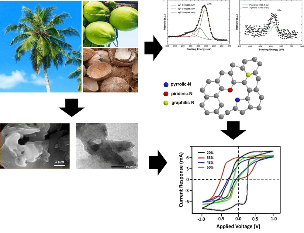
An rGO−like carbon compound has been synthesized from biomass, i.e., old coconut shell, by a carbonization process followed by heating at 400°C for 5 h. The nitrogen doping was achieved by adding the urea (CH4N2O) and stirring at 70°C for 14 h. The morphology and structure of the rGO-like carbon were investigated by electron microscopies and Raman spectroscopy. The presence of C-N functional groups was analyzed by Fourier transform infrared and synchrotron X-ray photoemission spectroscopy, while the particle and the specific capacitance were measured by particle sizer and cyclic voltammetry. The highest specific capacitance of 72.78 F/g is achieved by the sample with 20% urea, having the smallest particles size and the largest surface area. The corresponding sample has shown to be constituted by the appropriate amount of C–N pyrrolic and pyridinic defects.Graphic Abstract
Keywords
The access to electricity of the world population between 2010–2020 has reached 91%, up from 83%, with 1.3 billion people gaining access [1]. This is because, in this modern era, humans always need electrical energy to carry out daily activities. Various technologies that exist today, such as laptops and cell phones, require electrical energy storage. The storage system that has been widely used is the battery. Regardless, a battery has several disadvantages, among others, requiring a long time for recharging and having a small power density [2]. Energy storage devices that are more efficient and have a large capacity are therefore desirable. One of them is the supercapacitor [3]. Supercapacitors are a breakthrough in the world of energy storage devices. They have many advantages compared to other energy storage devices, especially batteries. From the technical point of view, supercapacitors have quick recharge capacity, longer discharge for a load, simple principles, and easy construction [4]. Supercapacitors also have a higher power density and a longer life cycle compared to batteries, as well as higher energy densities compared to conventional capacitors [5].
Based on the energy storage mechanism, supercapacitors are divided into two types, covering pseudocapacitors and electrical double-layer capacitors (EDLC) [6]. Materials used for the manufacture of supercapacitor electrodes include graphene [7], carbon nanotubes [8], carbon aerogel [9], porous carbon [10], and mineral composites-carbon [11]. Graphene is one of the interesting materials and has become a center of research in the last ten years because it has superior properties and wide potential in various fields such as nano-electronics, sensors, nanocomposites, batteries, supercapacitors, and transparent electrodes [12]. Reduced graphene oxide (rGO), a phase of graphene derivatives, is the result of the reduction of oxygen and hydrogen atoms, which undergo oxidation, but rGO still has a structure and properties similar to graphene. The rGO has a structure of single carbon bonds and carbon double bonds such as graphene, namely C–C and C=C, but the atomic lattice has defects in the carbon plane, so there are many impure bonds between C atoms with other atoms such as H, O, and N [13].
The application of the rGO as a supercapacitor electrode has several constraints. The agglomeration or clumping of the rGO sheet reduces the surface area and its specific capacitance. Therefore, it is necessary to add glucose as a barrier (spacer) between rGO layers [14–17]. Additionally, the rGO often agglomerates when used as an electrode material due to the Van der Waal’s forces between rGO sheets. Hence, the rGO needs to be sliced by ultrasonication in an acid solution. This method is known as the exfoliation technique. Based on research conducted by Al-Hazmi et al. [18], this technique has helped in stretching the layers between rGOs, so that thin layers are obtained, and as a result, the enlarging surface area can increase the specific capacitance. Research on the application of the rGO as a supercapacitor electrode has been carried out by Ghasemi et al. [19] employing Fe3O4, which resulted in a specific capacitance of 154 F/g. Balaji et al. [20] combined graphene and nitrogen materials through a supporting process, increasing the capacitance to 286 F/g. Furthermore, the combination of rGO and urea produced a capacitance of 514 F/g [21].
Meanwhile, the coconut shell, as abundant biomass (bio-waste), has a high carbon content exceeding 74.62%, making it a potential starting material for producing carbon compounds. This effort of synthesis has resulted in an rGO-based carbon containing a mixed structure of hybridized sp2 and sp3 orbitals. It forms an amorphous-like carbon dominated by an rGO phase of around 60%–70% combined with a minor diamond-like carbon (DLS) phase [13,22,23]. We report in this work that the rGO-like carbon derived from coconut shell has successfully been developed as a base constituent of EDLC. We are employing HCl to enlarge the distance between the sheets of the rGO structure, glucose as a spacer or barrier material between layers and to expand the surface area of rGO, and Fe3+ derived from FeCl3 as a constituent of pseudocapacitors. The insertion of nitrogen atom from urea to the obtained rGO is intended to increase the permittivity and is therefore expected to enhance the specific capacitance.
Initially, the old coconut shell as in Fig. 1, was cleaned, dried for 6 h in the open air, and then burned in an atmospheric environment until it became black charcoal. The charcoal was pulverized and then sieved using a 200 mesh. This sieving is aimed at creating a homogeneous size of the charcoal particles so that uniform heat distribution is attained when carbonized. The carbonization was carried out in a furnace in the air at 400°C for 5 h [22], which produces a graphic-based carbon phase of various thicknesses upon the exfoliation process using an acid solution. In this process, the as-synthesized carbon sample was then proceeded by adding 1 M HCl in a weight ratio of 1:1, then stirred while being mixed with FeCl3 and glucose until the ratio of rGO:HCl:FeCl3:glucose was 1:1:1:1. The solution was added with nitrogen (N) from urea (CH4N2O) having content 20% of weight, then it was exfoliated mechanically by ultrasonication for 6 h. The obtained result was dried with a temperature of 70°C for 5 h to become a completely dry powder. The powder was then molded into a pellet with a diameter of 13 mm and a weight of 0.5 grams. The pellet was then coated with silver paste, covering the entire surface. This pellet was marked as rGO-N20 sample. The other samples were prepared by a similar process with the N weight percentage of 33%, 43% and 50% and were marked as rGO-N33, rGO-N43 and rGO-N50, respectively. These samples served as the working electrodes.
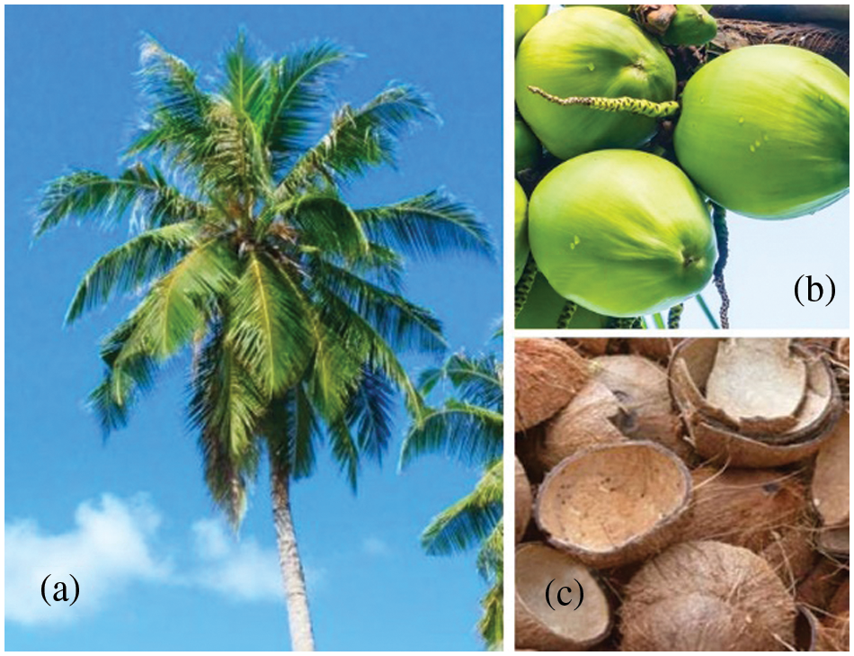
Figure 1: The coconut’s: a) tree, b) fruit, and c) shell
Structural characterizations to examine the phase formation and morphology were performed using X-ray diffraction (XRD, Philips X’Pert MPD) with Cu–Kα radiation in the diffraction angle range of 10° to 60°, scanning electron microscope (SEM, Zeiss Evo 10), and transmission electron microscope (TEM, Hitachi HT7700, operating at 120 kV), respectively. To study the possible formation of hexagonal (graphenic phase) carbon bonding, the Fourier transform infrared (FTIR, Shimadzu 8400S series) spectrometry and Raman (IHR320 HORIBA) spectroscopy were carried out. Meanwhile, the bonding between C and N atoms as a result of N atom insertion was analyzed utilizing a synchrotron X-ray photoemission spectroscopy (XPES) at beamline 3.2a at the Synchrotron Light Research Institute (SLRI), Thailand, using a photon energy range of 40–600 eV. By employing the Gaussian deconvolution functions with a Shirley-type background, the experimental spectra were fitted using software developed by SLRI as a part of the apparatus. Particle size and distribution were measured by the particle size analyzer (PSA) with the dynamic light scattering (DLS) technique (Malvern Nanozizer). The specific surface area of the samples was measured by the physisorption method (Quantochrome, Autosorb iQ).
Furthermore, the electrochemical property, especially the specific capacitance, was measured by cyclic voltammetry (CV). A conventional three-electrode configuration was applied to measure the specific capacitance of samples. The prepared sample served as the working electrode, while a Pt wire and an Ag/AgCl electrode were used as the counter and reference electrodes, respectively. A solution of 6 M KOH, a potential window of −1 to +1 volt, and a scan rate of 50 mV/s were employed in the CV measurements.
The structural and phase analysis of the resulting “pristine” sample (N-free) derived from old coconut-shell charcoal is shown as an XRD pattern in Fig. 2a. One can see that an amorphous feature characterized by broad diffraction peaks dominates the spectrum. There are two peaks at the diffraction angles (2θ) of 23.68° and 44.04°, being associated with the rGO phase, as indicated in previous reports [13,22,23]. The resulting wide peaks indicate the small crystal size of the rGO phase arranged in a short span of layers. This phase can be considered a part of graphite, which is still arranged randomly and without orientation, resulting in an amorphous-like structure. In this regard, we further consider that our sample is an rGO-like carbon. Meanwhile, Fig. 2b shows the Raman spectrum of the same sample as in Fig. 2a, possessing two remarkable characteristic peaks at 1344 and 1590 cm–1 corresponding to the well-defined a defect (D) and graphene (G) peaks, respectively. This result was in accordance with the experiment reported by Shimodaira et al. [24]. The D band, for graphene materials, is depicted as the A1g mode for the disordered carbon atoms at the edge or crystal defects [24,25], while the G band is the description of sp2-hybridized carbons with a Raman-active E2g in-plane vibration mode [24]. Thus, D band facilitates the formation of rich pore structures, and G band is beneficial for electron fast transportation in carbon materials. The intensity ratio of the two peaks (ID/IG) is 0.85, which is much greater compared to that of the flake graphite. This sample also exhibits significant defects, which are likely the consequences of the amorphous structure. The presence of the 2D peak at ∼2780 cm–1 further characterizes that the sample has two-dimensional characteristics, closely featuring a graphenic phase [26–28].
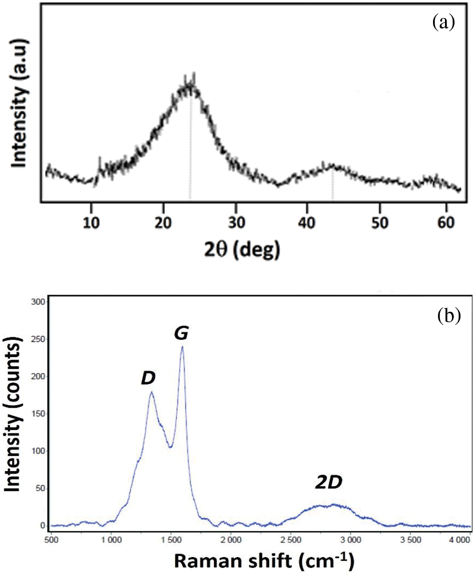
Figure 2: The structural characterisations of an as-prepared carbon sample: a) XRD pattern and b) Raman spectra
The morphology of the sample examined using SEM and TEM is presented in Figs. 3a and 3b, respectively. In both images, the sample appears to show a 2D arrangement in both the micrometer and nanometer scales. Fig. 3a shows that the structure stacks layer by layer and grows to produce a three-dimensional morphology like a flower. This reveals that this flower-like is a hierarchical structure composed of the growth of the petal-like layers, composed of thin plate-like grains. This image is corroborated by the experiment shown by Zhao et al. [28], supporting exactly the Raman spectroscopy with the appearance of the 2D peak. The pristine rGO is still sticky-thin and irregular sheet-like as observed by TEM in Fig. 3b, which indicates that the sample has formed inhomogeneous layers, and the particle size has varied. The agglomeration and overlapping between different particles are also observed in the images.
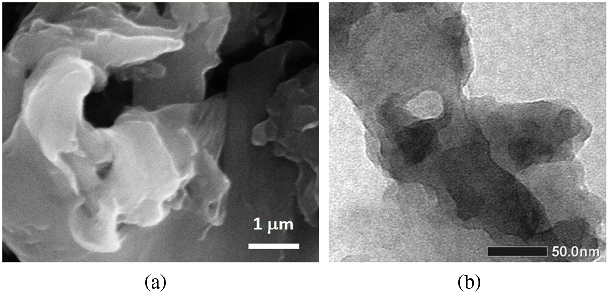
Figure 3: The images of: a) SEM and b) TEM from the related sampel as in Fig. 2
Given in Fig. 4 are the FTIR spectra of the 20% to 50% N-doped rGO. Generally, it can be seen that in the wavenumber range of 3300 to 3400 cm–1, two functional groups are detected, associated with the N–H and O–H functional groups. The wavenumber of N–H peak is between 3300 and 3500 cm–1, while that of the O–H peak is between 3200 and 3600 cm–1 [29]. In the lower range of the wavenumber, ∼2400 and 1150 cm–1, important peaks related to the C≡N and C–N functional groups are also detected. From the spectra, it can also be seen that samples having 20% and 33% of N are similar, while those of 43% and 50% are also the same regarding the appearance of the C–N functional groups. In short, the detection of the last two mentioned peaks implies that the N content increases with the increasing amount of urea added to the samples.
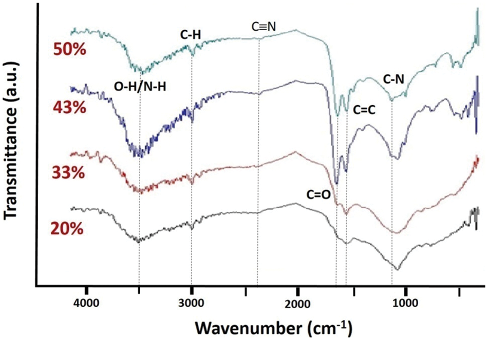
Figure 4: FTIR spectra of the samples doped with N from 20% to 50% as specified
As described earlier, the exfoliation process for reducing the particle’s thickness is achieved by ultrasonication of the sample in HCl solution. Because the size of the acid molecules is quite large compared to the distance between layers of the rGO, the inserted acid molecules will weaken the Van der Waals bond between the two layers and consequently widen the distance between them. This expected process is performed by stirring the rGO powder in the HCl solution using a magnetic stirrer at 70°C for 2 h, followed by ultrasonication. However, the presence of N atoms in the form of urea molecules will disturb the process of thinning layers together with the attachment of N onto C hexagonal network. The effect of N addition on the particle size of the samples is then evaluated by using a particle sizer (PSA) as presented in Fig. 5.
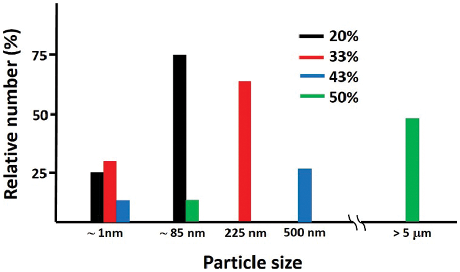
Figure 5: The particle’s size distribution of the N-doped samples
From Fig. 5, two peaks are identified, indicating that the powder size distribution in the solution is not homogeneous. All samples generally have two peaks, in which the first one has a size below 100 nm, ranging from 0.92 to 119.30 nm, with fairly low intensity. Meanwhile, the second one ranges from 79.98 to 5367.00 nm. The peak associated with the smallest size may correspond to the thickness (∼1 nm) of the rGO layer (∼2 layers), while one with a greater size may represent the cross-sectional/lateral diameter of the layers. Based on these results, it is known that the addition of urea leads to monotonically greater particle size. For urea content up to 50%, it appears that the particle size is larger, exceeding the micrometer scale. It can be imagined that the larger particle size distribution leads to a smaller surface area of the material, which becomes counter-productive in its role of higher specific capacitance. This means that in this study, the addition of much urea (CH4N2O) is not effective for supercapacitor electrodes. If too much urea is added, the nitrogen atom can probably not be separated from the urea. So, the urea molecule positions only above the rGO layer and agglomerates, leading to the particle size increasing up to a micrometer. Further measurement of the specific surface area has yielded 156.6 and 105.2 m2g−1, respectively, for samples with 20% and 50% urea.
The cyclic voltammetry (CV) curve of the samples is given in Fig. 6. It demonstrates that the electrode capacitance, visualized by the area inside the I-V curve, decreases with the increasing content of urea in the samples. The specific capacitance (C) can be determined from the I-V curve by Eq. (1) [30].
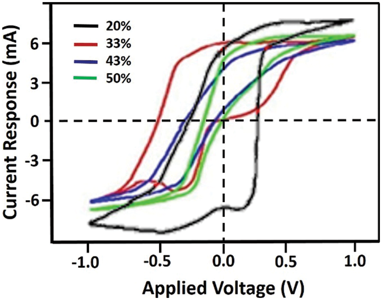
Figure 6: The CV’s measurement result of the samples
where m, v, V1, and V2 respectively represent the mass of the sample (in gram), the scan rate used, and the top and bottom potentials. The estimated specific capacitance according to the I-V in Fig. 6 is listed in Table 1.
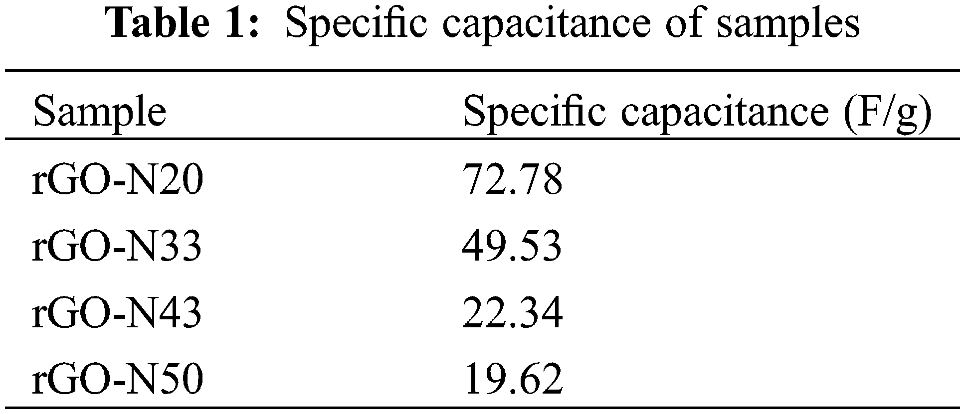
It can be seen in Table 1 that the higher specific capacitance of 72.78 F/g was achieved by the sample with the lowest N content (20%), and decreased monotonically and significantly with increasing N content. Meanwhile, the N-free sample has a specific capacitance of 23.63 F/g. Although the resulting specific capacitance is still lower than those of existing studies, both those using standard rGO [21] as well as those derived from biomass [31], this effort provides an opportunity for further performance improvement on this sample, particularly with regard to the sample’s thickness, which still has to be much reduced (Fig. 5). Anyway, the use of urea as a nitrogen source was proven to be more effective in inserting N atoms into the hexagonal C bonding network on the rGO structure. Compared to our previous samples, where N2 gas (bubbling process) and NH4OH were used as the source of N atoms, the samples with the best specific capacitance were 20.67 and 37.33 F/g, respectively [32]. On the basis of these results, it is clear that the N atom derived from the urea molecule is more capable of forming bonds with the C atom in rGO than those from N2 and NH4OH. To further examine the role of N in elevating the specific capacitance, let us deal with data from the characterization using the XPES.
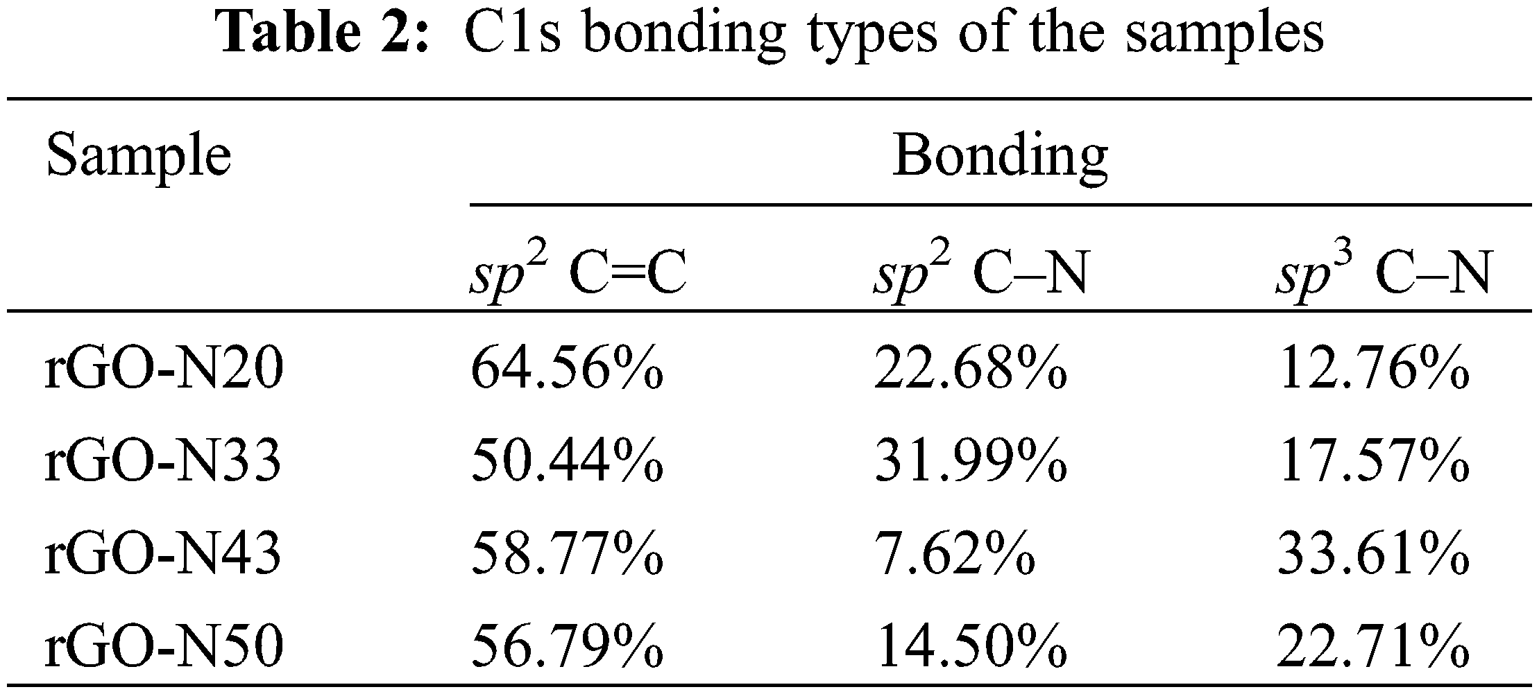
Fig. 7 is XPES data of the representative sample (rGO-N 20%) of the carbon (C1s) and nitrogen (N1s) spectra. The deconvolution spectra of C1s (Fig. 7a) show the presence of sp2 C=C, sp2 C–N, and sp3 C–N bonds, and based on the calculation over the area of the deconvoluted peaks, the bond’s contents are respectively 64.5%, 22.7%, and 12.8%. Furthermore, based on the spectra of the rest of the samples, which are not shown here, the total sp2 and sp3 bonding content involving N atoms (C–N) can reach up to almost ∼50% in the sample with the highest N (rGO-N50). Again, this fact confirms that the use of urea is very effective in inserting N atoms into rGO compounds, as mentioned above. In addition, the deconvolution result over the N1s spectrum (Fig. 7b) shows the presence of several bonding configurations between the C and N atoms, such as pyridinic, pyrrolic, graphitic-N, and others involving O atom [33], which create defects, as shown in Fig. 7c. The percentages of each bonding type/defect of C1s and N1s are listed in Tables 2 and 3.
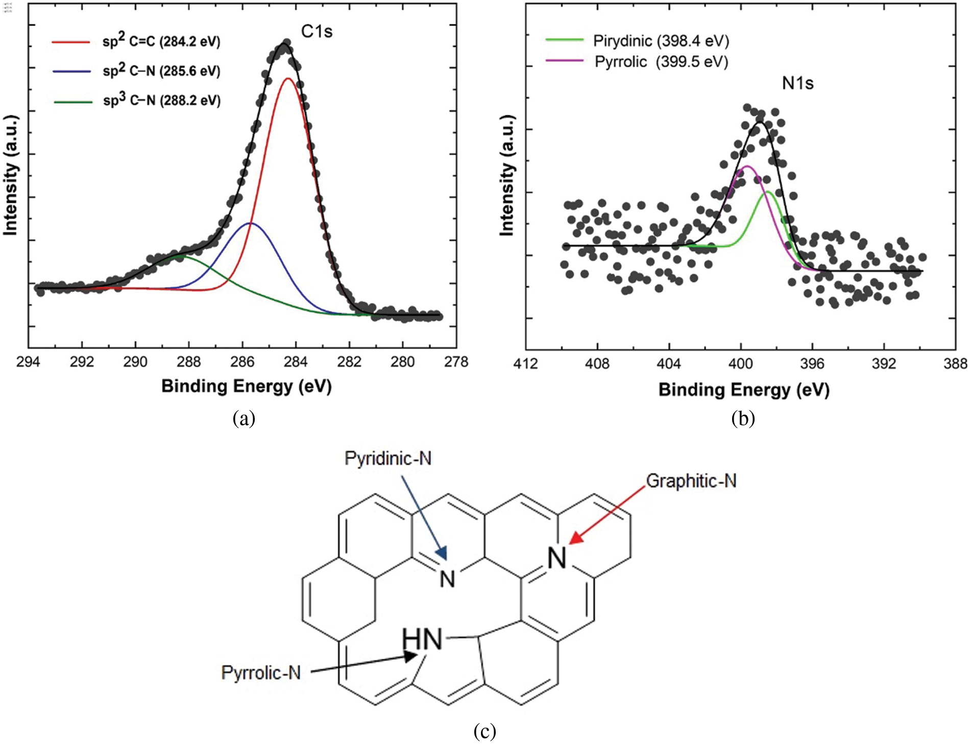
Figure 7: The representative XPES spectra of sample (rGO-N20): a) C1s, and b) N1s. c) The bonding types of C–N
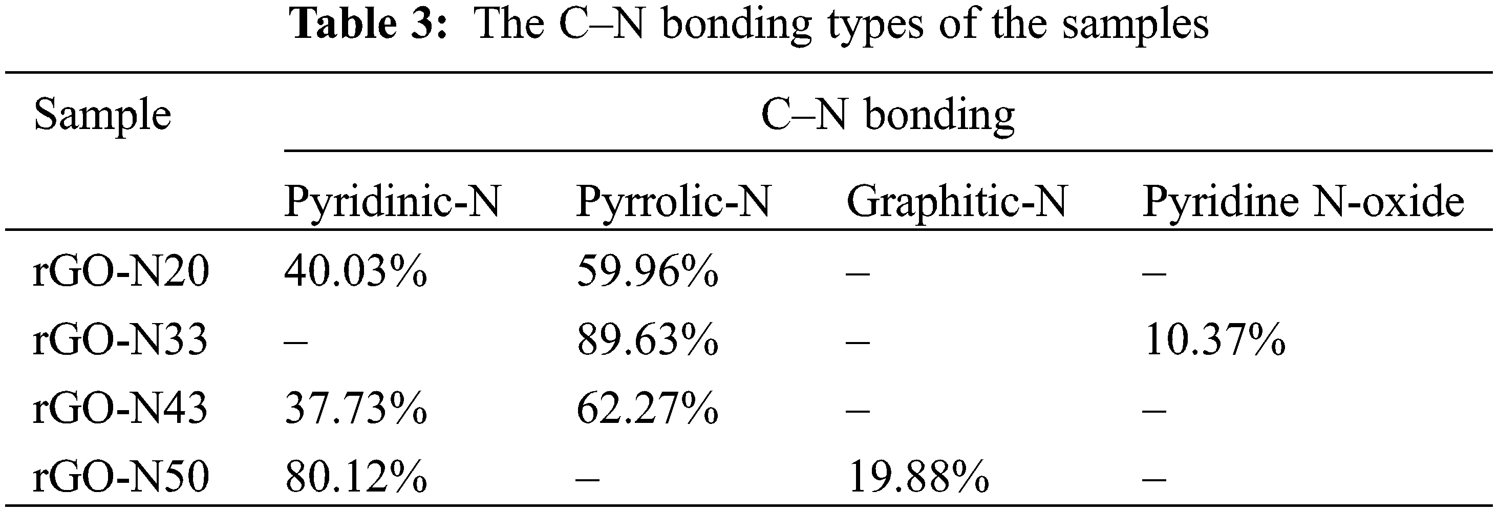
It is interesting to evaluate the presence of various C–N bonds, which appear to play an important role in determining the specific capacitance values of the samples. Based on Fig. 7c, it is conceivable that an electric dipole, which accompanies the bond between C and N, could form a positive charge around C and negative around N. Pyrrolic and pyridinic bonds provide such chances as to create larger electric dipoles, in addition to that created by other bonds. This mechanism can trigger a strengthening of the polarizability in the sample, which is directly related to the relative permittivity or dielectric constant and, therefore, the specific capacitance. In Table 3, only samples with 20% of urea content show the balanced presence of pyrrolic and pyridinic-N defects, while in the rest of the samples, there was a dominance of one defect, pyrrolic or pyridinic-N only, and other bonds such as graphitic-N or the oxide phase. The role of pyrrolic and pyridinic defects in amplifying electrochemical characteristics has also been previously reported in N-doped carbon-based compounds [34,35]. In addition, the two defective phases also affect the particle size of the compounds formed [34], as previously exhibited in Fig. 5.
In short, let us recall the following simple formulation of capacitance,
A carbon compound derived from coconut shell, as biomass, has successfully been synthesized employing the steps consisting of carbonization, heating, and doping with N. The prepared sample is dominated by sp2 hybridized carbon structure and the rest of sp3 one and other functional groups, which form an rGO-like phase. The N-doping introduced into the samples influences the particle’s size, being increased in the increasing content of N. In addition, the presence of N atom inserted in the hexagonal atomic network of C triggers the formation of defects of C–N, especially pyrrolic and pyridinic structures which take an important role in increasing polarizability and hence the dielectric constant of the samples. The best specific capacitance of 72.78 F/g is achieved by the sample doped with 20% of N (urea). The capacitance value decreases with the increasing content of N. This experiment has opened up opportunities and also challenges for the use of coconut shell, which is biomass, as a supercapacitor–an energy storage material, together with other biomass sources which have also been widely studied.
Funding Statement: One of us (IK) would like to thank the Ministry of Finance and the Ministry of Research, Technology, and Higher Education for providing the LPDP BUDI-DN scholarship. This work was partially supported by “Hibah Penelitian Dasar Kompetitif Nasional”, Ministry of Education, Culture, Research and Technology, Indonesia, 2021–2022 (D). The use of the synchrotron XPES facility at SLRI (Public Organization), Thailand, and some experimental facilities at UNIMAP and UPM, Malaysia, would also be appreciated.
Conflicts of Interest: The authors declare that they have no conflicts of interest to report regarding the present study.
References
1. United Nation (2022). Progress towards the sustainable development goals: Goal 7. https://sustainabledevelopment.un.org/content/documents/29858SG_SDG_Progress_Report_2022.pdf. [Google Scholar]
2. Volfkovich, Y. M. (2021). Electrochemical supercapacitors (a review). Russian Journal of Electrochemistry, 57(4), 311–347. DOI 10.1134/S1023193521040108. [Google Scholar] [CrossRef]
3. Kumar, R., Sahoo, S., Joanni, E., Singh, R. K., Maegawa, K. et al. (2020). Heteroatom doped graphene engineering for energy storage and conversion. Materials Today, 39, 47–65. DOI 10.1016/j.mattod.2020.04.010. [Google Scholar] [CrossRef]
4. Olabi, A. G., Abbas, Q., Al Makky, A., Abdelkareem, M. A. (2022). Supercapacitors as next generation energy storage devices: Properties and applications. Energy, 248, 123617. DOI 10.1016/j.energy.2022.123617. [Google Scholar] [CrossRef]
5. Petricca, L., Ohlckers, P., Chen, X. (2013). The future of energy storage systems. In: Zooba, A. F. (EdsEnergy storage-technologies and applications, pp. 113–130. UK: IntechOpen. DOI 10.5772/52413. [Google Scholar] [CrossRef]
6. Nagarajarao, S. H., Nandagudi, A., Viswanatha, R., Basavaraja, B. M., Santosh, M. S. et al. (2022). Recent developments in supercapacitor electrodes: A mini review. Chemical Engineering, 6(1), 5. DOI 10.3390/chemengineering6010005. [Google Scholar] [CrossRef]
7. Bokhari, S. W., Siddique, A. H., Sherrell, P. C., Yue, X., Karumbaiah, K. M. et al. (2020). Advances in graphene-based supercapacitor electrodes. Energy Reports, 6, 2768–2784. DOI 10.1016/j.egyr.2020.10.001. [Google Scholar] [CrossRef]
8. Zhu, S., Ni, J., Li, Y. (2020). Carbon nanotube-based electrodes for flexible supercapacitors. Nano Research, 13(7), 1825–1841. DOI 10.1007/s12274-020-2729-5. [Google Scholar] [CrossRef]
9. Lei, E., Gan, W., Sun, J., Wu, Z., Ma, C. et al. (2021). High-performance supercapacitor device with ultrathick electrodes fabricated from All-cellulose-based carbon aerogel. Energy & Fuels, 35(9), 8295–8302. DOI 10.1021/acs.energyfuels.0c04092. [Google Scholar] [CrossRef]
10. Shaker, M., Ghazvini, A. A. S., Cao, W., Riahifar, R., Ge, Q. (2021). Biomass-derived porous carbons as supercapacitor electrodes–A review. New Carbon Materials, 36(3), 546–572. DOI 10.1016/S1872-5805(21)60038-0. [Google Scholar] [CrossRef]
11. Khedekar, V., Mohammed Zaeem, S., Das, S. (2018). Graphene-metal oxide nanocomposites for supercapacitors: A perspective review. Advanced Materials Letters, 9(1), 2–19. DOI 10.5185/amlett.2018.1932. [Google Scholar] [CrossRef]
12. Wang, M., Yang, Y., Gao, W. (2021). Laser-engraved graphene for flexible and wearable electronics. Trends in Chemistry, 3(11), 969–981. DOI 10.1016/j.trechm.2021.09.001. [Google Scholar] [CrossRef]
13. Nugraheni, A. Y., Nasrullah, M., Prasetya, F. A., Astuti, F., Darminto. (2015). Study on phase, molecular bonding, and bandgap of reduced graphene oxide prepared by heating coconut shell. Materials Science Forum, 827, 285–289. DOI 10.4028/www.scientific.net/MSF.827.285. [Google Scholar] [CrossRef]
14. Rashid, A. R. A., Rosli, H. (2021). Green synthesis of reduced graphene oxide by using reducing sugars. Nano Hybrids and Composites, 31, 17–24. DOI 10.4028/www.scientific.net/NHC.31.17. [Google Scholar] [CrossRef]
15. Sunil, K. C., Suvarna, S., Nairy, R. K., Chethan, G., Mustak, M. S. et al. (2020). Facile, cost-effective and eco-friendly synthesis of carbonyl-rich partially reduced graphene oxide using glucose as a sole precursor. SN Applied Sciences, 2(8), 1–8. DOI 10.1007/s42452-020-3134-0. [Google Scholar] [CrossRef]
16. Sharma, K., Maiti, K., Kim, N. H., Hui, D., Lee, J. H. (2018). Green synthesis of glucose-reduced graphene oxide supported Ag-Cu2O nanocomposites for the enhanced visible-light photocatalytic activity. Composites Part B: Engineering, 138, 35–44. DOI 10.1016/j.compositesb.2017.11.021. [Google Scholar] [CrossRef]
17. Bhargava, R., Khan, S., Ansari, M. M. N., Ahmad, N. (2019). Green synthesis approach for the reduction of graphene oxide by using glucose. AIP Conference Proceedings, 2115(1), 030075. DOI 10.1063/1.5112914. [Google Scholar] [CrossRef]
18. Al-Hazmi, F. S., Al-Harbi, G. H., Beall, G. W., Al-Ghamdi, A. A., Obaid, A. Y. et al. (2015). Synthesis and structure of high quality graphene prepared via solvothermal exfoliation of intercalated graphite flakes. Superlattices and Microstructures, 86, 270–274. DOI 10.1016/j.spmi.2015.07.067. [Google Scholar] [CrossRef]
19. Ghasemi, S., Ahmadi, F. (2015). Effect of surfactant on the electrochemical performance of graphene/iron oxide electrode for supercapacitor. Journal of Power Sources, 289, 129–137. DOI 10.1016/j.jpowsour.2015.04.159. [Google Scholar] [CrossRef]
20. Balaji, S. S., Elavarasan, A., Sathish, M. (2016). High performance supercapacitor using N-doped graphene prepared via supercritical fluid processing with an oxime nitrogen source. Electrochimica Acta, 200, 37–45. DOI 10.1016/j.electacta.2016.03.150. [Google Scholar] [CrossRef]
21. Yadav, A., Kumar, R., Sahoo, B. (2022). Exploring supercapacitance of solvothermally synthesized N-rGO sheet: Role of N-doping and the insight mechanism. Physical Chemistry Chemical Physics, 24(2), 1059–1071. DOI 10.1039/d1cp03694g. [Google Scholar] [CrossRef]
22. Ristiani, D., Asih, R., Puspitasari, N. S., Baqiya, M. A., Kato, M. et al. (2020). Introduction of Na+ in reduced graphene oxide prepared from coconut shells and Its magnetic properties. IEEE Transactions on Magnetics, 56(7), 1–6. DOI 10.1109/TMAG.2020.2994175. [Google Scholar] [CrossRef]
23. Baqiya, M. A., Nugraheni, A. Y., Islamiyah, W., Kurniawan, A. F., Ramli, M. M. et al. (2020). Structural study on graphene-based particles prepared from old coconut shell by acid–assisted mechanical exfoliation. Advanced Powder Technology, 31(5), 2072–2078. DOI 10.1016/j.apt.2020.02.039. [Google Scholar] [CrossRef]
24. Shimodaira, N., Masui, A. (2002). Raman spectroscopic investigations of activated carbon materials. Journal of Applied Physics, 92(2), 902–909. DOI 10.1063/1.1487434. [Google Scholar] [CrossRef]
25. Wu, J. B., Lin, M. L., Cong, X., Liu, H. N., Tan, P. H. (2018). Raman spectroscopy of graphene-based materials and its applications in related devices. Chemical Society Reviews, 47(5), 1822–1873. DOI 10.1039/C6CS00915H. [Google Scholar] [CrossRef]
26. No, Y. S., Choi, H. K., Kim, J. S., Kim, H., Yu, Y. J. et al. (2018). Layer number identification of CVD-grown multilayer graphene using Si peak analysis. Scientific Reports, 8(1), 1–9. DOI 10.1038/s41598-017-19084-1. [Google Scholar] [CrossRef]
27. Yin, P., Lin, Q., Duan, Y. (2020). Applications of Raman spectroscopy in two-dimensional materials. Journal of Innovative Optical Health Sciences, 13(5), 2030010. DOI 10.1142/S1793545820300104. [Google Scholar] [CrossRef]
28. Zhao, Y., Huang, C., He, Y., Wu, X., Ge, R. et al. (2020). High-performance asymmetric supercapacitors realized by copper cobalt sulfide crumpled nanoflower and N, F co-doped hierarchical nanoporous carbon polyhedron. Journal of Power Sources, 456, 228023. DOI 10.1016/j.jpowsour.2020.228023. [Google Scholar] [CrossRef]
29. Ţucureanu, V., Matei, A., Avram, A. M. (2016). FTIR spectroscopy for carbon family study. Critical Reviews in Analytical Chemistry, 46(6), 502–520. DOI 10.1080/10408347.2016.1157013. [Google Scholar] [CrossRef]
30. Ke, Q., Tang, C., Liu, Y., Liu, H., Wang, J. (2014). Intercalating graphene with clusters of Fe3O4 nanocrystals for electrochemical supercapacitors. Materials Research Express, 1(2), 025015. DOI 10.1088/2053-1591/1/2/025015. [Google Scholar] [CrossRef]
31. Yu, S., Zhu, X., Lou, G., Wu, Y., Xu, K. et al. (2018). Sustainable hierarchical porous biomass carbons enriched with pyridinic and pyrrolic nitrogen for asymmetric supercapacitor. Materials & Design, 149, 184–193. DOI 10.1016/j.matdes.2018.04.023. [Google Scholar] [CrossRef]
32. Khambali, I., Ardiani, I. S., Kurniawan, A. R., Triwikantoro, Zainuri, M. et al. (2019). Synthesis of N-doped reduced graphene oxide from coconut shell as supercapacitors. Materials Science Forum, 966, 437–443. DOI 10.4028/www.scientific.net/MSF.966.437. [Google Scholar] [CrossRef]
33. Hao, J., Shu, D., Guo, S., Gao, A., He, C. et al. (2016). Preparation of three-dimensional nitrogen-doped graphene layers by gas foaming method and its electrochemical capactive behavior. Electrochimica Acta, 193, 293–301. DOI 10.1016/j.electacta.2016.02.048. [Google Scholar] [CrossRef]
34. Roy, N., Yasmin, S., Ejaz, A., Soon Han, H., Jeon, S. (2020). Influence of pyrrolic and pyridinic-N in the size and distribution behaviour of Pd nanoparticles and ORR mechanism. Applied Surface Science, 533, 147500. DOI 10.1016/j.apsusc.2020.147500. [Google Scholar] [CrossRef]
35. Il’ina, M., Il’in, O., Osotova, O., Khubezhov, S., Rudyk, N. et al. (2022). Pyrrole-like defects as origin of piezoelectric effect in nitrogen-doped carbon nanotubes. Carbon, 190, 348–358. DOI 10.1016/j.carbon.2022.01.014. [Google Scholar] [CrossRef]
Cite This Article
 Copyright © 2023 The Author(s). Published by Tech Science Press.
This work is licensed under a Creative Commons Attribution 4.0 International License , which permits unrestricted use, distribution, and reproduction in any medium, provided the original work is properly cited.
 Downloads
 Citation Tools