
 Submit a Paper
 Propose a Special lssue
 Open Access
SHORT COMMUNICATION

Treating CsPbI3 Perovskite with Pyrrolidinium Iodide to Improve the Performance of Perovskite Solar Cells
School of Materials Science and Engineering, Beihang University, Beijing, 100191, China
* Corresponding Author: Haining Chen. Email:
# These authors contributed equally
(This article belongs to the Special Issue: Perovskite Solar Cells)
Journal of Renewable Materials 2023, 11(8), 3193-3201. https://doi.org/10.32604/jrm.2023.027730
Received 12 November 2022; Accepted 05 December 2022; Issue published 26 June 2023
 View Full Text
 Download PDF
Abstract
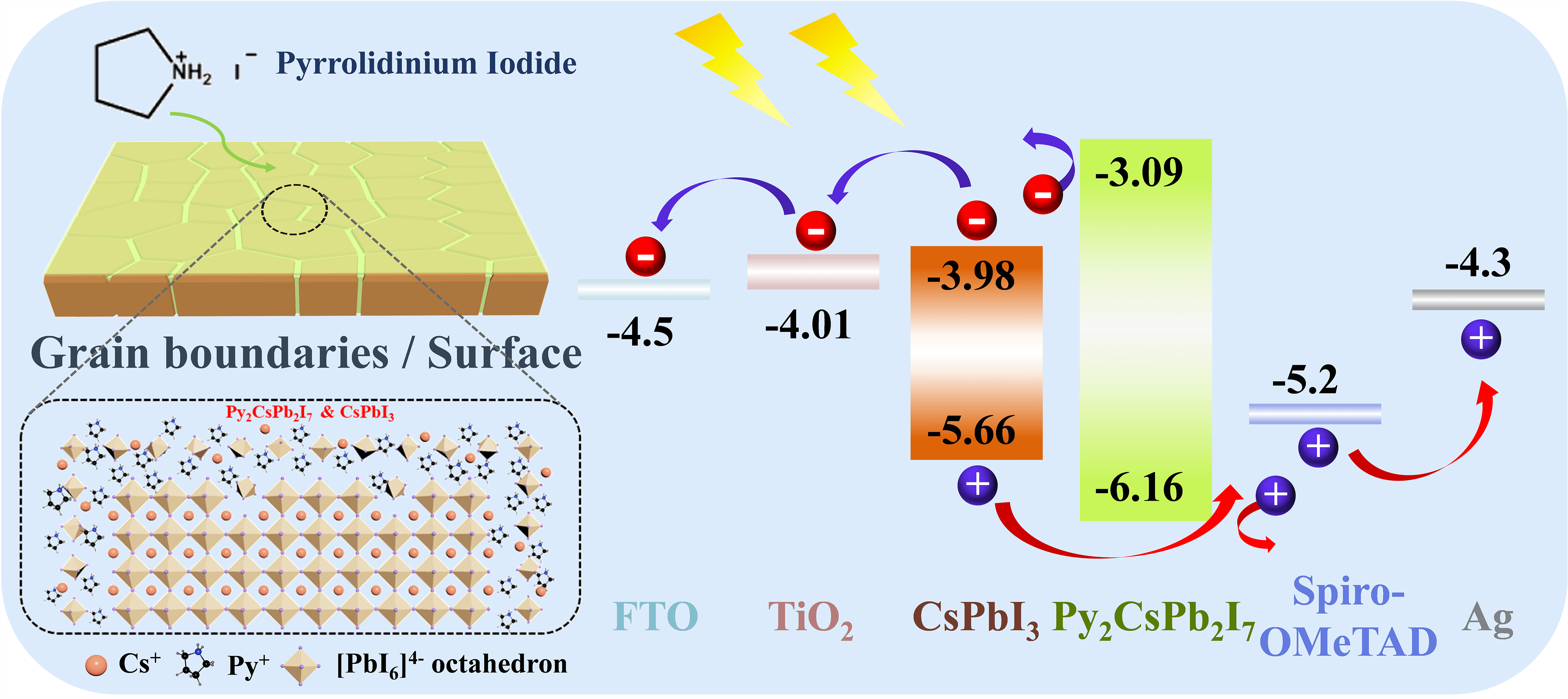
All-inorganic CsPbI3 perovskite has attracted wide attention due to its desirable optical bandgap (Eg: ∼1.7 eV) as well as high chemical stability. Nevertheless, the photovoltaic performance of CsPbI3 perovskite solar cells (PSCs) was limited by severe nonradiative charge recombination due to high defect density at the grain boundary and surface of perovskite films. To address this issue, a pyrrolidinium iodide (PyI) molecule was introduced to modify the surface and grain boundary of CsPbI3 perovskite films to passivate defects, which improves the quality of CsPbI3 perovskite films as well as induces the generation of a quasi-2D Py2CsPb2I7 capping layer between perovskite layer and hole transport layer. Such quasi-2D Py2CsPb2I7 capping layer optimizes interface contact between CsPbI3 perovskite layer and hole transport layer and blocks the electron transfer from CsPbI3 perovskite photoactive layer to the hole transport layer. As a result, the performance of CsPbI3 PSCs is well improved to 17.87% for power conversion efficiency (PCE) with an ultra-high fill factor (FF) of 0.84. In addition, the PyI molecule modified CsPbI3 perovskite devices exhibit excellent stability, which remains its initial PCE almost unchanged after aging for 35 days under the dry air atmosphere (temperature: 20°C–30°C, control relative humidity (RH): <10%).Graphic Abstract
Keywords
Supplementary Material
Supplementary Material FileOrganic-inorganic hybrid perovskite solar cells (PSCs) are considered one of the most promising candidates owing to the obvious advantages of tunable band gaps, high absorption coefficients and long carrier diffusion length [1–3]. So far, the PSCs have obtained a certified efficiency of 25.7% [4]. However, the low stability of organic-inorganic hybrid perovskites has inhibited the development and commercial application of PSCs [5–7]. Recently, all-inorganic perovskites have shown great promise in solving the above problem due to their higher chemical stability [8–10].
Among various inorganic perovskites, such as CsPbI3, CsPbI3−xBrx, and CsPbBr3, the full-I CsPbI3 perovskite is perceived as the most potential material because of its appropriate optical bandgap (Eg:
Herein, we reported an efficient defect passivation strategy to improve the performance of CsPbI3 PSCs by using a new organic ammonium halide, pyrrolidinium iodide (PyI). After the treatment, the quality of CsPbI3 perovskite films was significantly improved with optimized surface morphology and high crystallization. Especially, a quasi-2D Py2CsPb2I7 capping layer was formed on the CsPbI3 perovskite, which not only improved interface contact but also blocked electron transfer from CsPbI3 to hole transporter. As a result, the efficiency of CsPbI3 PSCs was well promoted to 17.87% with an ultra-high fill factor of 0.84, and the device stability was also improved.
CsI (99.9%), PbI2 (99.99%) and dimethylammonium iodide (DMAI) (99.5%), 2,2′, 7,7′-tetrakis (N,N-di-p-methoxyphenylamine)-9,9′-spirobifluorene (spiro-OMeTAD)), bis (trifluoromethane) sulfonamide lithium salt (Li-TFSi) (Li-TFSI), and 4-tert-butylpyridine (tBP) were used from Xi’an Polymer Light Technology Corp., China. DMF (99.8%, anhydrous), chlorobenzene (CB) (≥99.5%), Isopropanol (IPA) (≥99.7%), and acetonitrile (ACN) (≥99.9%) were purchased from Sigma Aldrich (Shanghai) Trading Co., Ltd., China. Titanium diisopropoxide (75 wt.% in isopropanol) was purchased from TCI (Shanghai) Development Co., Ltd., China. 1-butanol (99%) and ethanol (99.5%) were purchased from Shanghai Aladdin Biochemical Technology Co., Ltd., China.
The 0.15 M TiO2 blocking layer solution was obtained by mixing a titanium diisopropoxide bis(acetylacetonate) solution and 1-butanol. The CsPbI3 perovskite precursor solution with a concentration of 0.6 M was obtained by dissolving CsI, PbI2 and DMAI with a molar ratio of 1:1.3:1.3 (the CsI concentration is fixed at 0.6 M) in DMF. The spiro-OMeTAD solution was composed of 0.12 g spiro-OMeTAD, 19.3 μL Li-TFSi solution with a concentration of 520 mg/mL in ACN, and 17.58 μL tBP dissolved in CB. The PyI solution was dissolved in IPA solution with different concentrations of PyI (0.5, 1, 2, 3, 5, 10 and 30 mg/mL). A quasi-2D Py2CsPb2I7 solution was prepared by mixing PyI, CsI and PbI2 with a molar ratio of 2:1:1 in IPA.
The FTO conductive glass was firstly cleaned with successive sonication for 20 min in deionized water, ethyl alcohol and isopropyl alcohol, respectively. Then, TiO2 blocking layer solution was spin-coated onto FTO substrate with 2000 rpm for 20 s, and annealed at 550°C for 30 min. Then, the CsPbI3 perovskite layers were spin-coated on the c-TiO2/FTO substrate (3000 rpm, 30 s), followed by annealing at 210°C for 5 min (The deposition process was conducted in a dry air box with a <20% RH). Subsequently, for obtaining Py-CsPbI3 perovskite films, 70 μL PyI isopropanol solution was spin-coated on the surface annealed perovskite films and then heated at 100°C for 5 min. Then, the HTL was spin-coated with spiro-OMeTAD solution on perovskite films (control CsPbI3 and Py-CsPbI3) at 4000 rpm for 25 s. Finally, an Ag electrode layer with a thickness of 100 nm was evenly deposited by thermal evaporation at a constant evaporation rate of 0.3 Å/s.
A Rigaku D/MAX-2500 X-ray diffractometer obtained X-ray diffraction (XRD) patterns of the perovskite films with an X-ray tube Cu Ka radiation (λ = 1.5406 Å). The Scanning electron microscopy (SEM) images were obtained on a SUPRA55 SEM at an accelerating voltage of 5 kV. The optical absorption spectra of perovskite films were detected using a Shimadzu UV-3600 UV-vis spectrometer. Surface roughness of these films was characterized by a Bruker Dimension ICON atomic force microscopy (AFM). Chemical states and components of the perovskite film surface were analyzed using an X-ray photoemission spectroscopy (XPS, ESCALab250Xi). Time-resolved PL (TRPL) spectra were taken on an ultrafast lifetime Spectrofluorometer (Delta flex), and a 475 nm ultrafast laser was used as the excitation light source. The energy positions were recorded on ultraviolet photoelectron spectroscopy (UPS, ESCALab250Xi).
The photovoltaic performance of PSCs was tested using a solar light simulator (Newport Oriel Sol 3A, model number 94063A, AM 1.5 global filter, 100 mW/cm2) in ambient air. Current density-voltage (J-V) curves and dependence of Jsc and Voc on light intensity were measured on ZENNIUM pro electrochemical workstation (ZAHNER-Elektrik GmbH & Co., KG, Germany). The J-V curves were measured and recorded with a scanning speed of 100 mV/s to track the device’s performance.
The device stability for PSCs was tested by periodically recording J-V curves for storing non-encapsulated devices in an air atmosphere (RH < 10%, 20°C–30°C).
The deposition processes of the control CsPbI3 and Py-CsPbI3 perovskite films are illustrated in Fig. 1a. The XRD patterns in Fig. 1b indicate that all the samples show intense diffraction peaks at 14.3° and 28.8°, which could be indexed to the (100) and (200) planes of CsPbI3 perovskite, respectively. XPS spectrums (Figs. 1c and 1d, Fig. S1) were further used to confirm the deposition of PyI. As shown in Fig. 1c, the N1s core-level peaks appearing at 402.0 eV are ascribed to the N atoms from the pyrrolidinium group in Py-CsPbI3 sample, whereas it was not observed in the CsPbI3 sample. Meanwhile, the spectrum of C1s (Fig. 1d) for the Py-CsPbI3 samples displays three main peaks at 284.7, 285.0 and 286.0 eV (Marked as C1, C2, and C3, respectively), while only C1 is observed in the CsPbI3 sample. C1 should originate from DMA+ ions, while C2, and C3 should come from Py+ ions. Therefore, both XRD and XPS results demonstrate the deposition of PyI on CsPbI3 perovskite. UV-Vis absorption spectra in Fig. 1e, demonstrate that PyI post-treatment slightly dereases the absorption intensity, but the PyI treatment does not affect the absopton onset. SEM images in Fig. 1f show that both films display uniform and compact surface morphology, and no pinhole is observed. Different from the CsPbI3 film, many tiny grains are observed on the surface and the grain boundaries of the Py-CsPbI3 film. Atomic force microscopy (AFM) images in Fig. S2 further confirms the change in surface morphology after PyI treatment. Time-resolved PL (TRPL) spectra (Fig. 1g) reveals the significantly increased charge lifetime. The average charge lifetime is increased from 5.92 to 84.25 ns after PyI post-treatment, implying the suppressed nonradiative recombination and reduced defect density.
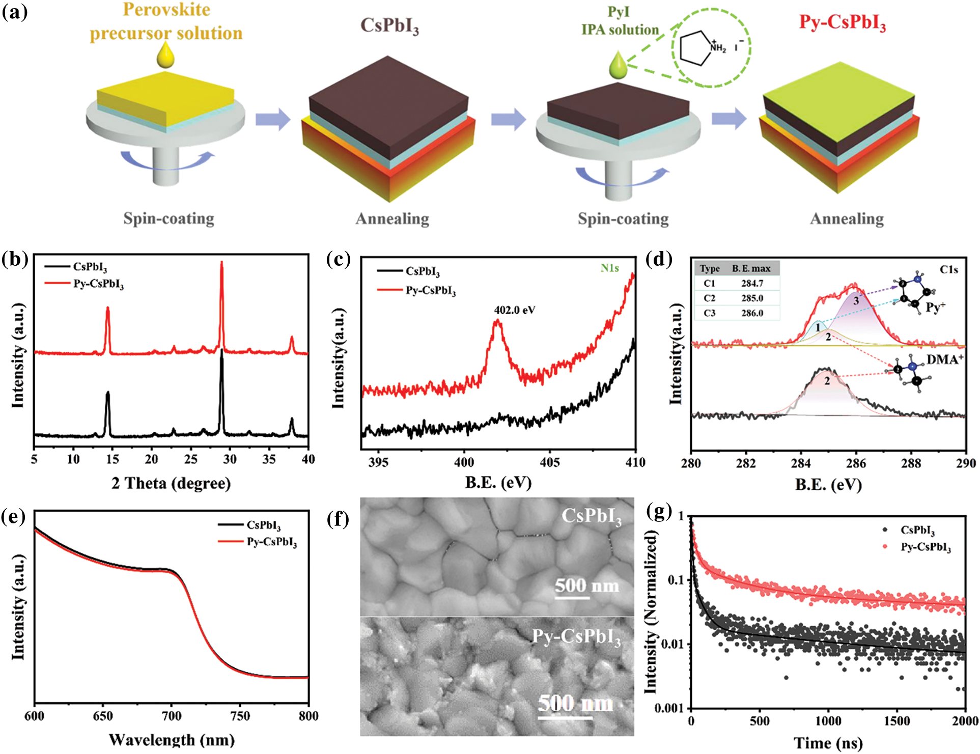
Figure 1: (a) Schematic illustration of the deposition of CsPbI3 perovskite layer and PyI post treatment. (b) XRD patterns of CsPbI3 and Py-CsPbI3 films annealed at 210°C for 5 min. XPS spectra and the fitted curves of the CsPbI3 and Py-CsPbI3 films: (c) N1s, (d) C1s, the inset depicts the structure of DMA+ and Py+ group and the core-level peaks marked as C1, C2, C3. (e) UV-vis absorption spectra, (f) SEM images and (g) TRPL spectra with the second-order fitted curves of the CsPbI3 and Py-CsPbI3 films
Although it has been proved that PyI has been deposited on the surface of the CsPbI3 perovskite films, it is still not clear whether PyI would react with CsPbI3 perovskite to form a new product. To make this clear, the PyI solutions with different concentrations were used to treat CsPbI3 perovskite films. As indicated in Figs. 2a–2d, with the PyI concentration increasing, more and more tiny crystals are formed on the surface, which is also confirmed by AFM images (Fig. S2). The UV-vis absorption spectra (Fig. 2e) display that PyI treatment does not affect the absorption onset, and the bandgap (Eg) is about 1.68 eV (Fig. S3), suggesting that the Py+ ions have not been incorporated into CsPbI3 perovskite crystals. A slight decrease in absorption intensity is observed for the Py-CsPbI3 films because the reaction between PyI and CsPbI3 perovskite would consume some CsPbI3 perovskite. The XRD patterns in Fig. 2f indicated that the pattern and peak intensity of the perovskite phase does not change obviously with PyI concentration. However, two new peaks located at 8.1° and 24.4° were observed with increasing the PyI concentration to 10 or 30 mg/mL, suggesting the formation of a new phase.
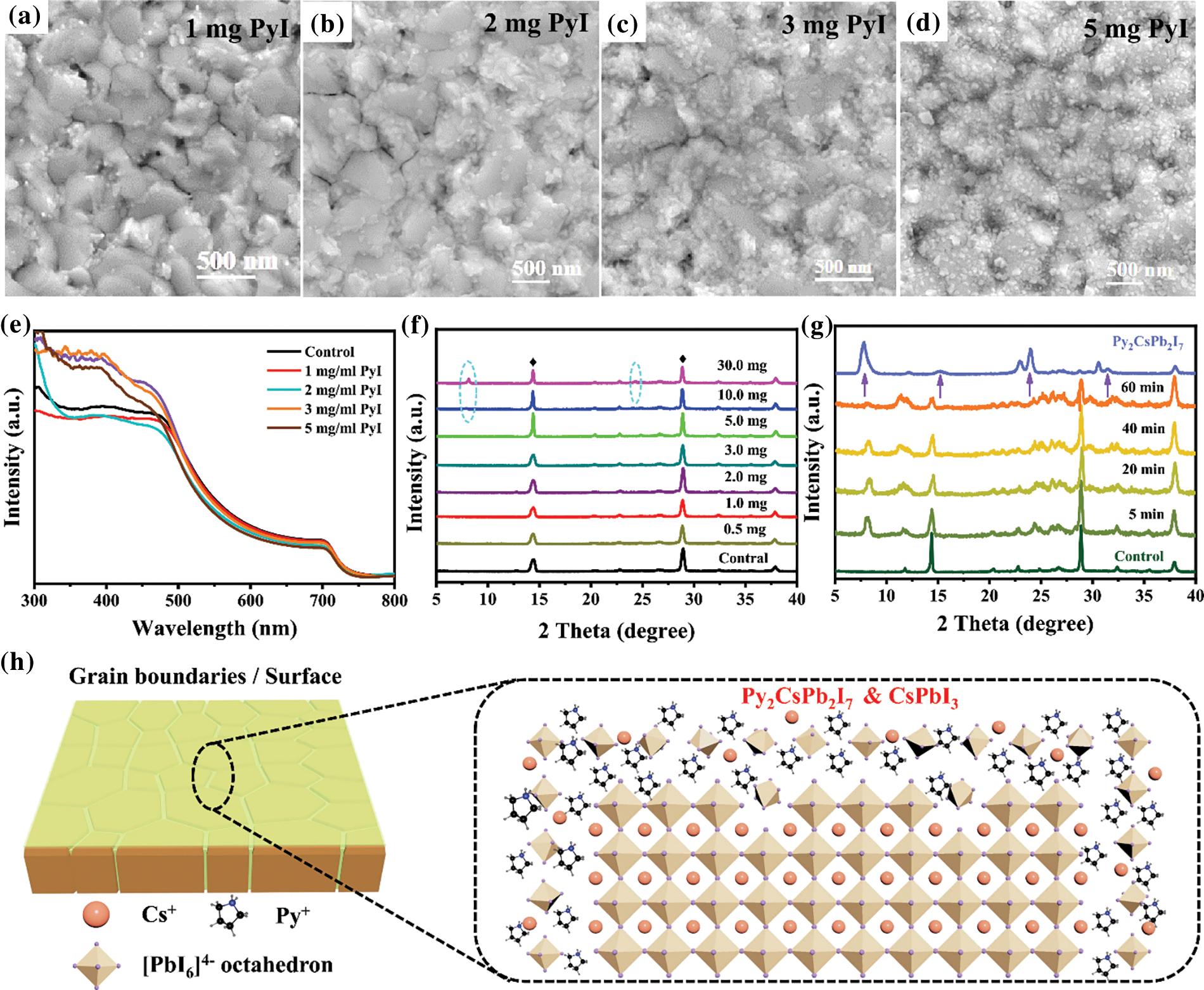
Figure 2: SEM images of different concentrations of PyI treated CsPbI3 films: (a) 1 mg/mL, (b) 2 mg/mL, (c) 3 mg/mL and (d) 5 mg/mL. (e) UV-vis absorption spectra of the CsPbI3 film and the Py-CsPbI3 films with different PyI concentrations. XRD patterns of (f) Py-CsPbI3 films with different PyI concentrations and (g) PyI-CsPbI3 perovskite films with the PyI concentration of 10 mg/ml that was annealed for different times and the Py2CsPb2I7 films. (g) The presumed interaction models of PyI towards CsPbI3 perovskite films
To better confirm the composition of the new product, the IPA solution with 10 mg/mL PyI is adopted, and the annealing time is varied. With the annealing time prolonging, the new diffraction peaks at about 8°, 16°, 24° and 32° are clearly observed (Fig. 2g) compared with those in Fig. 2f. Their peaks appear at equal increments and are characteristic of 00l type reflections of layered compounds, implying the possible formation of 2D perovskite. For further confirmation, a quasi-2D Py2CsPb2I7 sample was deposited on FTO substrate with a IPA solution containing PyI, CsI and PbI2 with a molar ratio of 2:1:1, which shows a similar XRD pattern with the new diffraction peaks. Therefore, the new product remained at the grain boundaries and surfaces may own a 2D structure, close to a quasi-2D Py2CsPb2I7 perovskite (Fig. 2h).
The photovoltaic (PV) performance of CsPbI3 and Py-CsPbI3 was evaluated by constructing the PSCs with the structure of FTO/TiO2/Perovskite/Sprio-OMeTAD/Ag (Fig. 3a). According to the ultraviolet photoelectron spectroscopy (UPS) results (Fig. S4 and Table S1) and UV-spectra of Py2CsPb2I7 (Fig. S5), the energy diagram of CsPbI3 PSCs is depicted in Fig. 3b [20–24]. As indicated, the higher CB of the Py2CsPb2I7 layer would effectively block electron transfer from the perovskite layer to HTL. The PV metrics in Figs. 3c–3f show that the Py-CsPbI3 devices achieve the enhanced average VOC values from 1.015 ± 0.07 to 1.082 ± 0.04 V and the enhanced average FF from 0.73 ± 0.09 to 0.74 ± 0.10 after 1 mg mg/mL PyI post-treatment. Compared with the CsPbI3 devices, the Py-CsPbI3 devices achieve a slightly higher JSC (18.84 ± 0.62 vs. 18.66 ± 0.78 mA/cm2). As a result, the average PCE of 15.98 ± 1.8% was obtained for the Py-CsPbI3 devices, whereas achieving 13.51 ± 2.1% for the CsPbI3 devices.
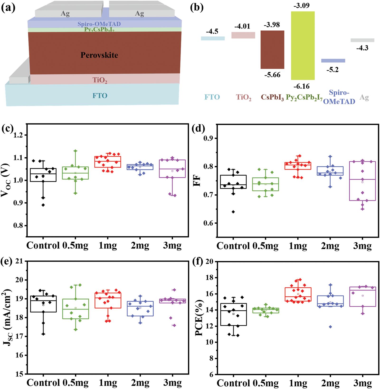
Figure 3: (a) The device architecture and (b) the schematic energy-level structure. PV performance of the CsPbI3 and Py-CsPbI3 PSCs: (c) VOC, (d) FF, (e) JSC and (f) PCE
Fig. 4a presents the J-V curves of the best CsPbI3 and Py-CsPbI3 devices. The CsPbI3 devices achieve the champion PCE of 15.10%, while the Py-CsPbI3 devices achieved a much higher PCE of 17.87%. In particular, the FF of CsPbI3 device has been significantly improved to 0.84 after PyI treatment owing to the defect passivation and the improvement of interface contact between perovskite layer and HTL. After aging for 35 days under the dry air atmosphere (temperature: 20°C–30°C, relative humidity: <10%), the PCE of the Py-CsPbI3 devices almost unchanged, whereas the PCE of the CsPbI3 devices reduces to 77% of its initial value (Fig. 4b). There, devices stability has also been significantly improved after PyI treatment. The J-V curves obtained from forward and reverse scan directions (Figs. 4c and 4d, Fig. S6) depict that the Py-CsPbI3 device has a smaller of hysteresis than the control CsPbI3 device. The transient photovoltage decay (TPV) results (Fig. S7) indicate that a longer charge-carrier lifetime was obtained for the Py-CsPbI3 device compared with the control CsPbI3 device, implying the carrier recombination is well inhibited in the Py-CsPbI3 device.
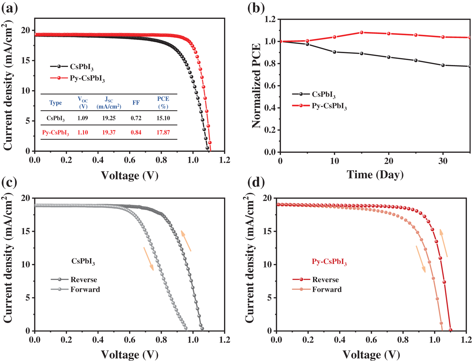
Figure 4: (a) The J-V curves of the best CsPbI3 and Py-CsPbI3 devices. (b) The change of PCE with time for CsPbI3 and Py-CsPbI3 devices stored in a dry air box (temperature: 20°C–30°C, relative humidity: <10%). Both reverse and forward scans of J-V curves for control CsPbI3 and Py-CsPbI3, (c) CsPbI3, (d) Py-CsPbI3
We have developed a facile and effective defect passivation strategy to modify the surface and grain boundary of CsPbI3 perovskites by using PyI. After treatment, we obtained a high-quality CsPbI3 perovskite film with compact, pinhole-free and low roughness. And a quasi-2D Py2CsPb2I7 capping layer formed on the surface well passivated the defect in perovskite, suppressed the nonradiative recombination, optimized the interface contact, and blocked the electron transfer from the perovskite layer to HTL. As a result, a champion PCE of 17.87% was achieved for CsPbI3 PSCs with an ultra-high FF of 0.84, and the device stability was also improved by PyI treatment.
Acknowledgement: This work is financially supported by the National Natural Science Foundation of China and the Beijing Natural Science Foundation.
Funding Statement: National Natural Science Foundation of China, Grant No. 21875013, H.N. Chen. Beijing Natural Science Foundation, Grant No. 2182031, H.N. Chen.
Conflicts of Interest: The authors declare that they have no conflicts of interest to report regarding the present study.
Reference
1. Bu, T., Ono, L. K., Li, J., Su, J., Tong, G. et al. (2022). Modulating crystal growth of formamidinium–caesium perovskites for over 200 cm2 photovoltaic sub-modules. Nature Energy, 7, 528–536. [Google Scholar]
2. Li, N., Luo, Y., Chen, Z., Niu, X., Zhang, X. et al. (2020). Microscopic degradation in formamidinium-cesium lead iodide perovskite solar cells under operational stressors. Joule, 4(8), 1743–1758. [Google Scholar]
3. Liu, K., Luo, Y., Jin, Y., Liu, T., Liang, Y. et al. (2022). Moisture-triggered fast crystallization enables efficient and stable perovskite solar cells. Nature Communications, 13, 4891 [Google Scholar] [PubMed]
4. NREL National Center for Photovoltaics (2022). https://www.nrel.gov/pv/cell-efficiency.html. [Google Scholar]
5. Chen, H., Wei, Z., Yan, K., Yi, Y., Wang, J. et al. (2014). Liquid phase deposition of TiO2 nanolayer affords CH3NH3PbI3/nanocarbon solar cells with high open-circuit voltage. Faraday Discuss, 176, 271–286 [Google Scholar] [PubMed]
6. Liu, C., Yuan, J., Masse, R., Jia, X., Bi, W. et al. (2020). Interphases, interfaces, and surfaces of active materials in rechargeable batteries and perovskite solar cells. Advanced Materials, 33(22), 1905245. [Google Scholar]
7. Wang, P., Li, R., Chen, B., Hou, F., Zhang, J. et al. (2020). Gradient energy alignment engineering for planar perovskite solar cells with efficiency over 23%. Advanced Materials, 32(6), 1905766. [Google Scholar]
8. Chen, H., Xiang, S., Li, W., Liu, H., Zhu, L. et al. (2018). Inorganic perovskite solar cells: A rapidly growing field. Solar RRL, 2(2), 1700188. [Google Scholar]
9. Chen, H., Yang, S. (2019). Methods and strategies for achieving high-performance carbon-based perovskite solar cells without hole transport materials. Journal of Materials Chemistry A, 7(26), 15476–15490. [Google Scholar]
10. Wang, Y., Liu, X., Zhang, T., Wang, X., Kan, M. et al. (2019). The role of dimethylammonium iodide in CsPbI3 perovskite fabrication: Additive or dopant? Angewandte Chemie International Edition, 58(46), 16691–16696 [Google Scholar] [PubMed]
11. Liu, J., Zhu, L., Xiang, S., Wang, H., Liu, H. et al. (2019). Cs-doped TiO2 nanorod array enhances electron injection and transport in carbon-based CsPbI3 perovskite solar cells. ACS Sustainable Chemistry & Engineering, 7(19), 16927–16932. [Google Scholar]
12. Xiang, S., Fu, Z., Li, W., Wei, Y., Liu, J. et al. (2018). Highly air-stable carbon-based α-CsPbI3 perovskite solar cells with a broadened optical spectrum. ACS Energy Letters, 3(8), 1824–1831. [Google Scholar]
13. Xiang, S., Li, W., Wei, Y., Liu, J., Liu, H. et al. (2018). The synergistic effect of non-stoichiometry and Sb-doping on air-stable alpha-CsPbI3 for efficient carbon-based perovskite solar cells. Nanoscale, 10(21), 9996–10004 [Google Scholar] [PubMed]
14. Jiang, Y., Yuan, J., Ni, Y., Yang, J., Wang, Y. et al. (2018). Reduced-dimensional α-CsPbX3 perovskites for efficient and stable photovoltaics. Joule, 2(7), 1356–1368. [Google Scholar]
15. Meng, W., Hou, Y., Karl, A., Gu, E., Tang, X. et al. (2019). Visualizing and suppressing nonradiative losses in high open-circuit voltage n-i-p-type CsPbI3 perovskite solar cells. ACS Energy Letters, 5(1), 271–279. [Google Scholar]
16. Wang, X., Wang, Y., Chen, Y., Liu, X., Zhao, Y. (2021). Efficient and stable CsPbI3 inorganic perovskite photovoltaics enabled by crystal secondary growth. Advanced Materials, 33(44), e2103688 [Google Scholar] [PubMed]
17. Zhang, J., Liu, J., Tan, A., Piao, J., Fu, Z. (2020). Improved stability of β-CsPbI3 inorganic perovskite using pi-conjugated bifunctional surface capped organic cations for high performance photovoltaics. Chemical Communications, 56, 13816–13819 [Google Scholar] [PubMed]
18. Zhang, S., Zhang, L., Tian, Q., Gu, X., Du, Y. et al. (2021). Spontaneous construction of multidimensional heterostructure enables enhanced hole extraction for inorganic perovskite solar cells to exceed 20% efficiency. Advanced Energy Materials, 12, 2103007. [Google Scholar]
19. Tan, S., Yu, B., Cui, Y., Meng, F., Huang, C. et al. (2022). Temperature-reliable low-dimensional perovskites passivated black-phase CsPbI3 toward stable and efficient photovoltaics. Angewandte Chemie International Edition, 61(23), e202201300 [Google Scholar] [PubMed]
20. Che, Y., Liu, Z., Duan, Y., Wang, J., Yang, S. et al. (2022). Hydrazide derivatives for defect passivation in pure CsPbI3 perovskite solar cells. Angewandte Chemie International Edition, 61(33), e202205012 [Google Scholar] [PubMed]
21. Gu, X., Xiang, W., Tian, Q., Liu, S. F. (2021). Rational surface-defect control via designed passivation for high-efficiency inorganic perovskite solar cells. Angewandte Chemie International Edition, 60(43), 23164–23170 [Google Scholar] [PubMed]
22. Liu, J., Ozaki, M., Yakumaru, S., Handa, T., Nishikubo, R. et al. (2018). Lead-free solar cells based on Tin halide perovskite films with high coverage and improved aggregation. Angewandte Chemie International Edition, 57(40), 13221–13225 [Google Scholar] [PubMed]
23. Zhang, J., Fang, Y., Zhao, W., Han, R., Wen, J. et al. (2021). Molten-salt-assisted CsPbI3 perovskite crystallization for nearly 20%-efficiency solar cells. Advanced Materials, 33(45), 2103770. [Google Scholar]
24. Zhang, L., Guo, T., Liu, B., Du, D., Xu, S. et al. (2022). Intermediate-phase-modified crystallization for stable and efficient CsPbI3 perovskite solar cells. ACS Appllied Materials & Interfaces, 14(17), 19614–19622 [Google Scholar]
Supplementary Materials
Figure S1: XPS spectrum of the blank CsPbI3 and 1 mg/ml PyI treated CsPbI3
Figure S2: AFM images of the Py-CsPbI3 perovskite films
Figure S3: The corresponding Tauc-plots for the blank CsPbI3 and different concentration of PyI treated CsPbI3 films
Figure S4: The valence band edges and cutoff regions of UPS spectra
Figure S5: (A) UV-vis spectra of Py2CsPb2I7 and (B) corresponding Tauc-plots
Figure S6: Reverse and forward scans of J-V curves for the Py-CsPbI3 devices with different PyI concentrations: (A) 0.5 mg/mL, (B) 1 mg/mL, (C) 2 mg/mL and (D) 3 mg/mL
Figure S7: The transient photovoltage decay (TPV) curves of CsPbI3 and Py-CsPbI3 devices
Table S1: Data related to energy level information of CsPbI3 and Py-CsPbI3 films
Cite This Article
 Copyright © 2023 The Author(s). Published by Tech Science Press.
This work is licensed under a Creative Commons Attribution 4.0 International License , which permits unrestricted use, distribution, and reproduction in any medium, provided the original work is properly cited.
 Downloads
 Citation Tools