
 Submit a Paper
 Open Access
ARTICLE

Research on Stick-Slip Vibration Suppression Method of Drill String Based on Machine Learning Optimization
School of Petroleum Engineering, Chongqing University of Science and Technology, Chongqing, 401331, China
* Corresponding Author: Jian Wei. Email:
Sound & Vibration 2023, 57, 97-117. https://doi.org/10.32604/sv.2023.043734
Received 10 July 2023; Accepted 08 September 2023; Issue published 14 December 2023
 View Full Text
 Download PDF
Abstract
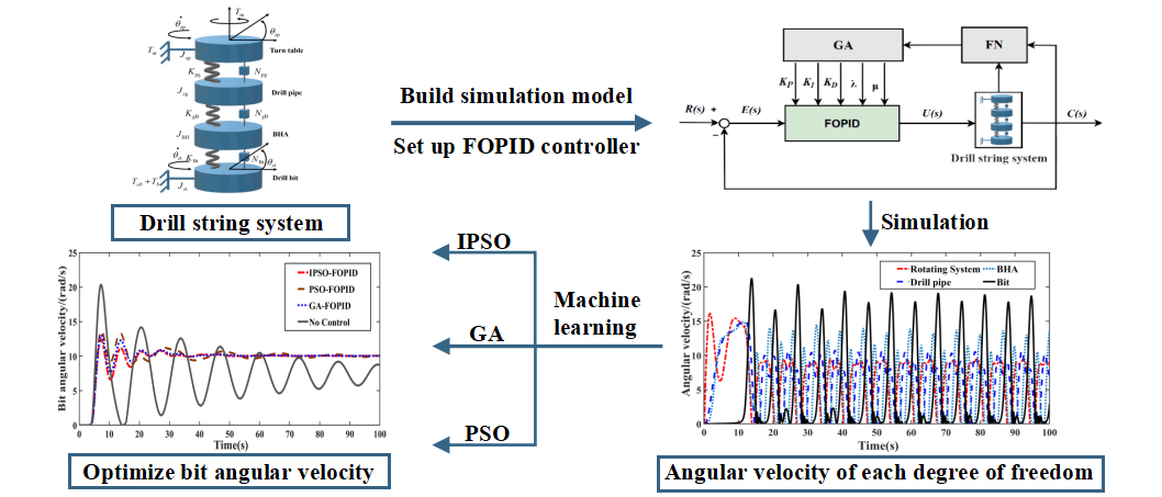
During the drilling process, stick-slip vibration of the drill string is mainly caused by the nonlinear friction generated by the contact between the drill bit and the rock. To eliminate the fatigue wear of downhole drilling tools caused by stick-slip vibrations, the Fractional-Order Proportional-Integral-Derivative (FOPID) controller is used to suppress stick-slip vibrations in the drill string. Although the FOPID controller can effectively suppress the drill string stick-slip vibration, its structure is flexible and parameter setting is complicated, so it needs to use the corresponding machine learning algorithm for parameter optimization. Based on the principle of torsional vibration, a simplified model of multi-degree-of-freedom drill string is established and its block diagram is designed. The continuous nonlinear friction generated by cutting rock is described by the LuGre friction model. The adaptive learning strategy of genetic algorithm (GA), particle swarm optimization (PSO) and particle swarm optimization improved (IPSO) by arithmetic optimization (AOA) is used to optimize and adjust the controller parameters, and the drill string stick-slip vibration is suppressed to the greatest extent. The results show that: When slight drill string stick-slip vibration occurs, the FOPID controller optimized by machine learning algorithm has a good effect on suppressing drill string stick-slip vibration. However, the FOPID controller cannot get the drill string system which has fallen into serious stick-slip vibration (stuck pipe) out of trouble, and the machine learning algorithm is required to mark a large amount of data on adjacent Wells to train the model. Set a reasonable range of drilling parameters (weight on bit/drive torque) in advance to avoid severe stick-slip vibration (stuck pipe) in the drill string system.Graphic Abstract
Keywords
Nomenclature
| | Drill bit viscous damping [(N · m · s)/rad] |
| | Viscous damping coefficient of the turn table [(N · m · s)/rad] |
| | Rotational inertias of the turn table, drill pipe, BHA, and drill bit, respectively [kg · m2] |
| | Torsional stiffness of the springs between the turn table and drill pipe, drill pipe and BHA, and BHA and drill bit, respectively [(N · m)/rad] |
| | Torsional damping of the springs between the turn table and drill pipe, drill pipe and BHA, and BHA and drill bit, respectively [(N · m · s)/rad] |
| | Radius of the drill bit [m] |
| | Viscous damping torque at the top drive system [N · m] |
| | Viscous damping torque at the drill bit [N · m] |
| | Torque at the drill bit [N · m] |
| | Sliding friction torque (Coulomb friction torque) [N · m] |
| | Turn table driving torque [N · m] |
| | Coupling torque of the drilling column [N · m] |
| | Maximum static friction torque between the drill bit and the rock [N · m] |
| | Angular displacements of the turn table, drill pipe, BHA, and drill bit, respectively [rad] |
| | Angular velocities of the turn table, drill pipe, BHA, and drill bit, respectively [rad/s] |
| | Angular accelerations of the turn table, drill pipe, BHA, and drill bit, respectively [rad/s2] |
| | Rigidity coefficient of the bristles [N · m · s-1] |
| | Relative motion velocity of the contact surface [m/s] |
| | Striebeck velocity [m · s-1] |
| | Weight on Bit (WOB) [kN] |
| | Damping coefficient of the drilling string [N · m · s-1] |
| | Stiffness coefficient of the drilling string [N · m · s-1] |
| | Static friction factor |
| | Coulomb friction factor of the bit |
| | A positive number less than 1 |
| | Average elastic deformation of the bristles [m] |
| | Output of the fractional-order controller |
| | Error signal of the system |
| | Fractional derivative operator |
| | Output of the control system |
| | Weight coefficients, taking the values of 0.5 and 0.7, respectively |
| | Population size |
| | Dimension of the search space |
| | Position of the first solution in the j-dimensional of the space |
| r2 | Random number uniformly distributed in [0,1] |
| | i-th solution for the next iteration |
| | Position of i-dimensional solution in the j-dimensional of the space |
| | Limit value, a random proportion coefficient used to generate more diversified processes and explore different regions of the search space |
| | Upper and lower bounds of the optimal value in the j-dimensional of the space to prevent the solution from going out of bounds after updating the individual |
| | Control parameter used to adjust the exploration process |
| | Learning factor of particle i |
| | Minimum value of the learning factor, which is set to 0.7 |
| | Maximum value of the learning factor, which is set to 3 |
| | Ranking of the fitness of particle i |
| | Population size (total number of particles) |
| | The j-th position in the current optimal solution |
| | The velocity of a particle during the (k+1)-th iteration in the iterative process of the standard Particle Swarm Optimization (PSO) algorithm |
| | Inertia weight coefficient of particle motion |
| | Particle acceleration coefficient |
| | The optimal position of i-th particle in and before the k iteration |
| | The position of particle i in the search population during the (k+1)-th iteration |
| | The best position reached by all particles in the swarm up to the k-th iteration |
| | The minimum and maximum values of particle velocity |
Stick-slip vibration is an important factor that reduces drilling efficiency. Suppressing stick-slip vibration can reduce accidents in the wellbore, shorten the construction period to some extent, and reduce drilling costs [1,2]. The torsional energy produced by the stick-slip vibration accumulates in the intermediate drill string, which makes the down-hole drill string more prone to fatigue damage [3,4]. Therefore, it is important to design a drive controller that can automatically control the bit on weight and the top drive speed to eliminate the torsional energy stored in the drill string [5]. For the stick-slip vibration drill string dynamic model, Depouhon et al. [6] simplified the downhole drilling system into a two-degree-of-freedom drill string model using the torsional vibration principle and the spring-rotational inertia model. Navarro-Lopez et al. [7] described the downhole dynamic system using a multi-degree-of-freedom torsional model, and both proved that changes in drilling parameters would affect drill string stick-slip vibration. Richard et al. [8] found that the nonlinear friction generated by the contact between the drill bit and the rock was the main cause of stick-slip vibration. To suppress and eliminate the effects of stick-slip vibration, Khulief [9] combined control engineering with drill string stick-slip vibration research, using Laplace transform to process the drill string dynamic differential equations. Smit [10] proposed to apply optimal control to the suppression research of drill string viscous stick-slip vibration. Canudas-De-Wit et al. [11] and others verified that adjusting drilling parameters can suppress drill string viscous stick-slip vibration. Tucker et al. [12] used PI (Proportional Integral) and PID (Proportion Integration Differentiation) control to adjust drilling parameters to achieve the purpose of suppressing drill string stick-slip vibration. Yousefi et al. [13] used a more complex FOPID controller to suppress stick-slip vibration in the drill string. Karkoub et al. [14] and others optimized the PID controller parameters using genetic algorithms based on the drill string torsional model. Navarro-López et al. [15] used a sliding mode control strategy to design an intelligent controller to suppress drill string stick-slip vibration, which can achieve optimal control effect. Tavakkoli-Moghaddam et al. [16] combined particle swarm optimization with bacterial foraging algorithms to optimize FOPID controller parameters to improve the robustness of the control system. These methods can help drilling engineer better control drill string stick-slip vibration, improve drilling efficiency and safety.
Lyu et al. [17] established a general multidimensional drill string torsional dynamic equation based on the mechanical characteristics of drilling tools such as turn tables, drill pipes, drill collars, and drill bits. Fu et al. [18] proposed a control scheme combining state feedback and torque feed forward to suppress drill string stick-slip vibration and achieved good suppression effect. Zhang et al. [19] proposed to use an FOPID controller to adjust drilling parameters to suppress drill string stick-slip vibration based on a multi-degree-of-freedom dynamic model.
In classical control theory, PI, PD, PID and other controllers can effectively solve linear problems, but the control effect of classical controller is not as good as that of modern control theory FOPID controller when facing nonlinear problems. PID controller is a special case of FOPID controller parameter rounding. FOPID controller has a wider parameter adjustment range, and its flexible and complex structure makes its parameter adjustment more complicated.
With the development and improvement of machine learning algorithms, some algorithms are used to adjust controller parameters. Gad et al. [20] used multi-objective genetic algorithm (MOGA) to optimize FOPID controller parameters to improve vehicle ride stability. Mohaghegh et al. [21] applied the parameter optimization method of multi-objective optimization to the study of drill string stick-slip vibration. Muftah et al. [22] adopted particle swarm optimization algorithm to optimize fuzzy FOPID controller and applied it to pneumatic cylinder system to improve the robustness of the system. Mohamed et al. [23] used genetic algorithm (GA) and particle swarm optimization (PSO) algorithm to optimize PID controller and applied it in the control system of shred DC motor to improve the performance of the system. In the above research, the characteristics of multi-objective optimization of machine learning algorithm and the advantages of overcoming the sensitivity of initial parameter values of simplex method were utilized to optimize controller parameters [24,25]. In this paper, machine learning algorithms [26] are used to optimize the controller parameters, improve the robustness of the control system, increase the control accuracy, and suppress the drill string stick-slip vibration to the greatest extent.
2 Modeling of Viscous Stick-Slip Vibration Drilling Control Object
2.1 Dynamic Modeling of Drill String System
The simplified drill string torsional model in this paper consists of four parts: turn table, drill pipe, bottom hole assembly (BHA), and drill bit. The model elements are interconnected by linear springs with torsional stiffness and torsional damping [27]. Viscous damping torque is considered at the top drive system and drill bit. Nonlinear friction torque generated by dry friction and rock cutting at the drill bit is considered [28,29]. The simplified drill string system model is shown in Fig. 1.
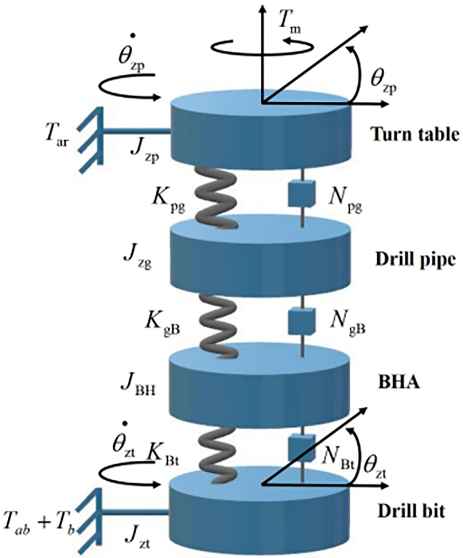
Figure 1: Torsional vibration model of drill string
The dynamic equation of the drill string system is shown in Eq. (1):
Let
A schematic diagram of a four-degree-of-freedom drilling column system based on the state equation is designed (Eq. (2)), the structure as shown in Fig. 2.
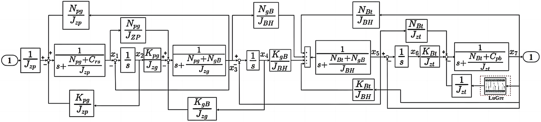
Figure 2: 4-DOF drill string system structure block diagram
2.2 Nonlinear Friction Model Modeling
Using the LuGre friction model to simulate the continuous nonlinear frictional force generated by drilling rock with drill bit. The LuGre friction model is used to simulate the continuous nonlinear friction generated by drill cutting rock. This model can not only accurately describe the phenomenon of increased static friction force and friction memory, but also use Stribeck curve in the model to describe the behavior that the friction force. The force subjected to the drill bit decreases with the increase of speed after overcoming the maximum static friction force in the low speed zone when the drill string is experiencing stick-slip vibration. It can also describe the dynamic and static properties such as friction hysteresis, pre-slip displacement and variable static friction. Therefore, the LuGre friction model is chosen as the research model. The definition of the LuGre friction model [30] is as follows:
Due to the uncertainty of the maximum static friction force, the model is divided into two states determined by velocity: stick and slip. When
where,
The structural diagram of the LuGre friction model is shown in Fig. 3:
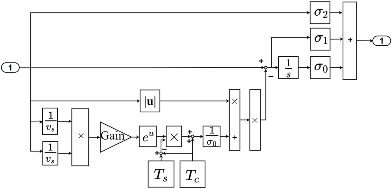
Figure 3: LuGre friction model
3 Optimization of FOPID Controller Using Machine Learning Algorithms
3.1 Design of FOPID Controller
The use of FOPID controller can effectively suppress stick-slip vibration of the drilling string and improve the robustness of the control system [31]. Compared with the traditional PID controller, the FOPID controller has an additional integral order λ and derivative order μ. The integer-order PID control can be understood as a special case of FOPID control when the derivative and integral terms are rounded to integers [32,33]. The output of the FOPID controller can be described as follows:
By using the relationship between input and output variables and applying Laplace transform, the transfer function of the FOPID controller is obtained.
To achieve the fitting calculation of the fractional derivative operator, the conventional Oustaloup filter does not provide satisfactory fitting results at the endpoints of the fitting frequency band. Therefore, an improved Oustaloup filter proposed in reference [34] is considered, which is described as follows:
In Eq. (11):
where,
3.2 Optimization of FOPID Controller Using Genetic Algorithm (GA)
The parameter design methods of FOPID controller are mostly obtained through equation derivation or extensive search. By using intelligent optimization algorithms [35,36] to optimize the controller parameters, the control accuracy of the FOPID controller can be improved as Fig. 4 shows.
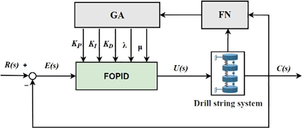
Figure 4: GA-FOPID controller
Genetic algorithm is used to encode the five parameters in the FOPID controller, and five chromosomes are constructed: proportional, integral, derivative, integral order λ, and derivative order μ, each assigned to a chromosome and encoded using a binary character set. The maximum number of evolution generations is set, and a certain number of individuals N are randomly generated. The randomly encoded initial string data of N chromosomes are used as initial points for iteration until the number of individuals in the initial population reaches a certain size, and then the iteration is stopped.
In this paper, the ITAE (integral of time multiplied by absolute value of error) criterion is selected to represent the performance index:
The fitness function is defined as follows:
The classical method for calculating the adaptive operator was proposed by Srinvivas et al. [37]. However, since most of the excellent individuals in the initial population have very small changes, using this adaptive method in the early stages of evolution can easily overlook the global optimal solution and fall into a local optimal solution. Therefore, an improved adaptive calculation equation is used to calculate the crossover operator
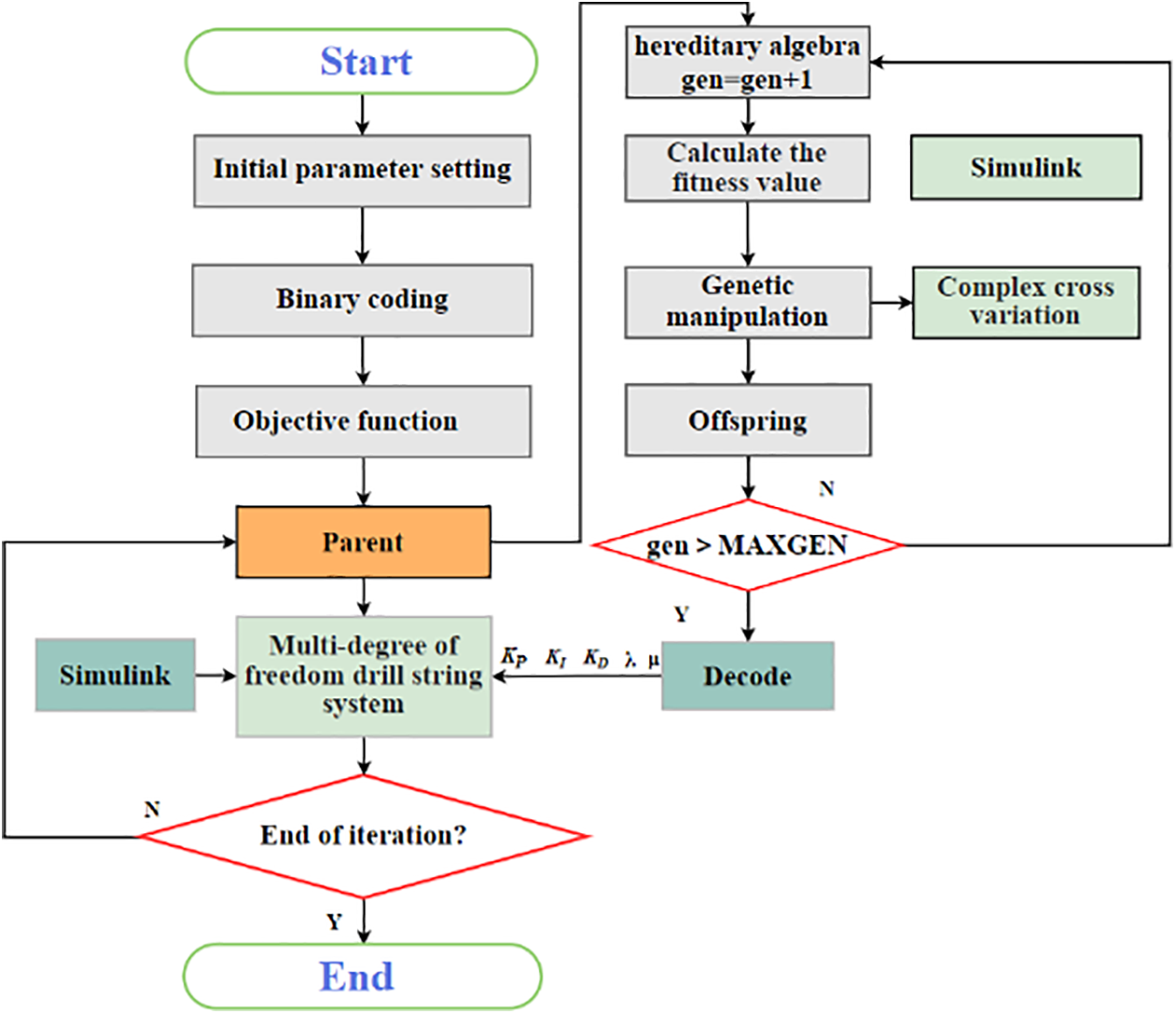
Figure 5: Genetic algorithm (GA) optimization of FOPID controller parameters process
Step 1: Use empirical methods to determine the five parameters of the FOPID controller (
Step 2: Calculate the fitness value of the initialized particles, the average fitness value of the particles, and the error of the current fitness value based on the selected fitness function.
Step 3: Use the evaluation function to calculate the corresponding fitness value of each individual and calibrate and transform the fitness function.
Step 4: Select suitable parents from the population and perform adaptive crossover and mutation based on the crossover and mutation probability formulas.
Step 5: Determine whether the termination condition is met based on the error accuracy and total number of iterations. If the condition is met, proceed to Step 6. If not, return to Step 2.
Step 6: Decode the optimized values of the five subgroups of parameters and output the corresponding fitness values.
3.3 Optimization of FOPID Controller Parameters Using Improved Particle Swarm Optimization (IPSO) Algorithm
3.3.1 Optimization of FOPID Controller Parameters Using Particle Swarm Optimization (PSO) Algorithm
Use the PSO algorithm to optimize the five parameters of the FOPID controller, including the proportional coefficient, integral coefficient
The steps for particle swarm optimization of FOPID controller parameters are as follows in Fig. 6:
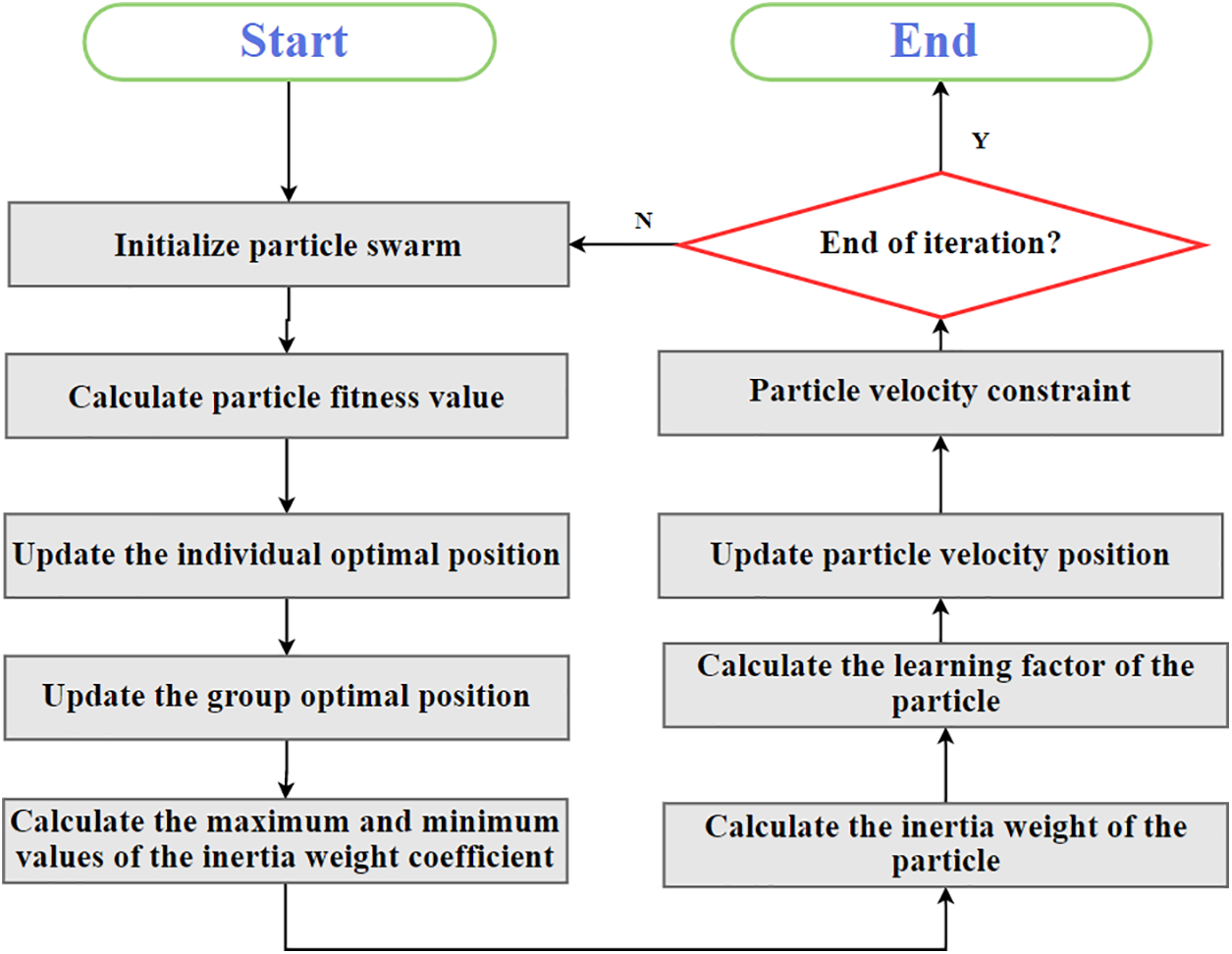
Figure 6: Particle swarm optimization (PSO) optimization of FOPID controller parameters process
Step 1: Determine the objective function. First, it is necessary to determine the objective function to be optimized, which is the performance index of the FOPID controller that needs to be optimized, such as steady-state error, overshoot, response time, etc.
Step 2: Determine the parameter range. Determine the parameter range of the FOPID controller, that is, the range of values for each parameter. This helps to limit the search space and improve search efficiency.
Step 3: Initialize the particle swarm. Initialize a certain number of particle swarms, each particle representing a combination of FOPID controller parameters, and the initial position can be randomly generated.
Step 4: Calculate the fitness function. Calculate the fitness function value of each particle based on the objective function, which is the performance index of the FOPID controller.
Step 5: Update particle position. Based on the fitness function value of the particle and the historically best position, update the position and velocity of each particle to move towards a better position.
Step 6: Determine the termination condition. Determine whether the termination condition has been reached, such as reaching the maximum number of iterations or the objective function value reaching a certain accuracy requirement.
3.3.2 Optimizing FOPID Controller Parameters Using IPSO Algorithm
To improve the global dispersion of particle swarm position updates, enhance the global optimization ability of the algorithm, overcome premature convergence, and achieve global exploration and optimization, the multiplication and division operator strategy of the Arithmetic Optimization Algorithm [40] is used for global search to improve the particle swarm algorithm.
The Arithmetic Optimization Algorithm (AOA) initializes the population by generating random numbers using Eq. (15).
The exploration phase operators of AOA are multiplication (M) and division (D), which have high dispersion and are conducive to global exploration. The mathematical model of this phase is:
The Math Optimizer Probability (MOP) is a coefficient calculated using the following formula:
The development phase operators of AOA are addition (A) and subtraction (S), which have significantly lower dispersion and can easily approach the target. Therefore, strengthening the connection between S and A to support the development phase is conducive to faster convergence to the optimal solution. The mathematical model of this phase is:
The specific steps to improve PSO are as follows in Fig. 7:
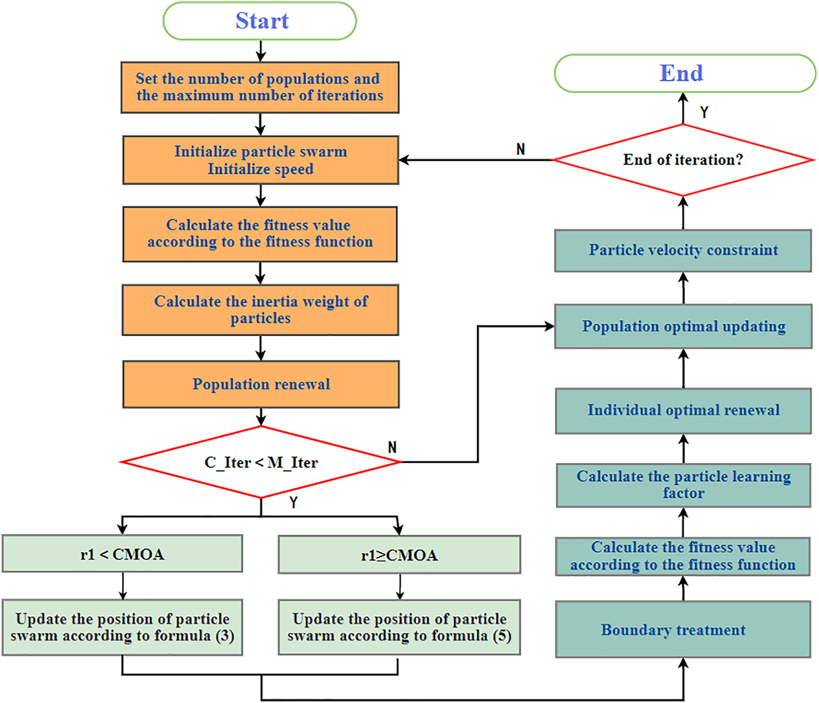
Figure 7: Improved particle swarm optimization (IPSO) optimization of FOPID controller parameters process
Step 1: Initialize the particle swarm parameters. Set the population size and maximum number of iterations, range of the learning factor, range of the inertia weight, range of particle velocity, and set boundary conditions.
Step 2: Calculate the fitness value based on Eq. (14).
Step 3: Calculate the particle inertia weight coefficient based on Eqs. (20) and (21).
In Eqs. (20) and (21),
Step 4: Update the best position of the population and particle individuals. Calculate based on Eqs. (16) and (18). If r1 < CMOA, perform exploration and update the position based on Eq. (16); if r1 ≥ CMOA, perform development and update the position based on Eq. (18).
Step 5: Calculate the learning factor based on Eqs. (22) and (23).
Step 6: Update the particle velocity and position based on Eqs. (24) and (25).
Step 7: Particle velocity constraint. Calculate according to Eq. (26).
Step 8: Maximum iteration reached or global. The optimal position meets the minimum limit. If reached, exit. Otherwise, return to step 1 to continue iteration.
The main parameters [41] of the simulation experiment for the stick-slip vibration system are as follows: Jzp = 920 kg · m2, Jzg = 2775 kg · m2, JBH = 740 kg · m2, Jzt = 480 kg · m2, Kpg = 679 (N ·m)/rad, KgB = 1070 (N · m)/rad, KBt = 915 (N · m)/rad, Npg = 145 (N · m)/rad, NgB = 195 (N · m)/rad, NBt = 180 (N · m)/rad, Crs = (N · m · s)/rad, Cpb = 50 (N · m · s)/rad, Wb = 80.5 kN,
4.1 Simulation of Drill String System (without FOPID Control)
When the drill string stick-slip vibration occurs, the drill bit is in an alternating state of stickiness and slippage, and the direction of friction subjected to the drill bit is constantly changing. The LuGre friction model is used to simulate this phenomenon to ensure the accuracy of the simulation experiment. Neglecting the small differences in the LuGre friction model parameters in the positive and negative directions, taking the motor-driven torque Tm = 28 kN · m and the Wb = 80.5 kN as an example, the friction torque curve of the LuGre friction model and the Stribeck curve are shown in Figs. 8 and 9.
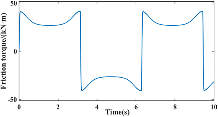
Figure 8: Friction torque curve
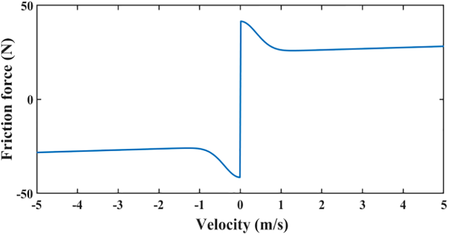
Figure 9: Stribeck curve
From Figs. 8 and 9, it can be seen that when the drill bit angular velocity is in the zero speed interval, the frictional force gradually increases to its maximum. When the drill bit is in an alternating state of stick-slip, the direction of the frictional force keeps switching.
After the drill string system model is established, the stick-slip vibration simulation experiment of the drill string system is carried out, and the angular velocity and angular displacement of the four degrees of freedom of the rotary table, drill pipe, BHA and drill bit are simulated respectively. When the system is started, the angular velocity of the turn table is the largest, followed by that of the drill pipe, and that of the drill bit is the smallest. The simulation results further verify the accuracy of the drill string model.
From Fig. 10a, it can be seen that at the beginning of the simulation, the drill pipe and BHA start to rotate with the top drive, and the drill bit starts to rotate and alternates between stick-slip states when it overcomes the maximum static friction force of the rock contact. When the drill bit slips, its angular velocity reaches 2–3 times that of the turn table angular velocity. From Fig. 10b, it can be seen that when the drill bit sticks, the angular displacement of each degree of freedom remains parallel to the time axis and does not change. This system can simulate the stick-slip vibration of the drill string.
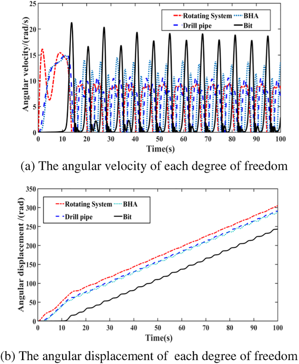
Figure 10: Angular velocity and angular displacement curves of each degree of freedom of drill string system
According to the study of the influence of single factor on the dynamic behavior of drill string stick-slip vibration system, the methods to suppress drill string stick-slip vibration are obtained: (1) Increase the rotational inertia of rotary disc and drill collar; (2) Reduce the moment of inertia between the drill pipe and the controlled object; (3) Reduce the stiffness of drill collar; (4) Adjust weight on bit and speed. In this paper, a top-drive controller that can adjust bit weight and rotary speed is used to suppress drill string stick-slip vibration. It is necessary to verify whether the simulation model established by adjusting bit weight and rotational speed can inhibit drill string sticky-slip vibration. The simulation results are shown in Figs. 11 and 12.
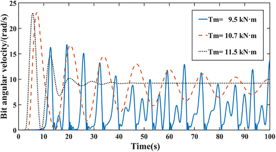
Figure 11: Variation curve of bit angular velocity under different torques
Figure 12: Variation curve of bit angular velocity under different WOB
Fig. 11 shows the changes in the drill bit angular velocity. Keeping the
In Fig. 12, keep the drive torque
Adjusting the drilling parameters within a certain range can suppress stick-slip vibration of the drill string, but excessive
4.2 Using Machine Learning Algorithms to Optimize the Parameters of the FOPID Controller
The rotary speed/weight on bit is taken as the input of the drill string system, and the bit angular speed is taken as the output of the drill string system. The FOPID controller is used to control the rotary speed/weight on bit single-factor, and the control effect of the FOPID controller is reflected by the change of the bit angular speed. The FOPID controller can suppress stick-slip vibration of the drill string, but the complex structure of the FOPID controller and the difficulty in adjusting its parameters often cannot achieve optimal performance. In this study, three algorithms, namely Genetic Algorithm (GA), Particle Swarm Optimization (PSO), and Improved Particle Swarm Optimization (IPSO), were used to optimize the five parameters of the FOPID controller to achieve maximum suppression of stick-slip vibration of the drill string. This study divided stick-slip vibration into two categories: severe stick-slip vibration (stuck pipe) and general stick-slip vibration (non-stuck pipe). When general stick-slip vibration occurs (non-stuck), set a constant
When there is no stuck pipe, the results of optimizing the FOPID controller parameters using machine learning algorithms are as follows in Table 1:
In Fig. 13, when there is no stuck pipe phenomenon, IPSO-FOPID and GA-FOPID have good suppression effects on stick-slip vibration when it occurs. Among them, IPSO-FOPID control optimization has a stronger effect than GA-FOPID and PSO-FOPID control, with the smallest fitness value. It can be seen from Fig. 13d that IPSO algorithm tends to be stable after 87 iterations, and corresponding Fig. 13e shows that 5 parameters vary widely before 87 iterations and do not change after 87 iterations, indicating that IPSO algorithm improved by AOA algorithm has better parameter searching ability and is not easy to fall into local optimal solution. IPSO-FOID controller has strong control ability.
Figure 13: Control effect of GA-FOPID, GA-PID for moderate stick slip of drill string
When severe stick-slip vibration (stuck pipe) occurs, set a constant
The results of optimizing FOPID controller parameters using machine learning algorithms when a drill bit gets stuck are as follows in Table 2:
In Fig. 14, when a drill bit gets stuck, the controller has a good suppression effect on non-stuck situations. When the bit is stuck, the bit angular velocity and bit torque fluctuate greatly. It can be seen from Figs. 14d and 14e that IPSO algorithm tends to be stable after about 60 iterations, and its fitness value becomes very large, and parameters still have a large range of variation, indicating that IPSO algorithm still has a strong optimization effect, but the controller itself has limited adjustment ability, and cannot make the bit out of the stuck state.
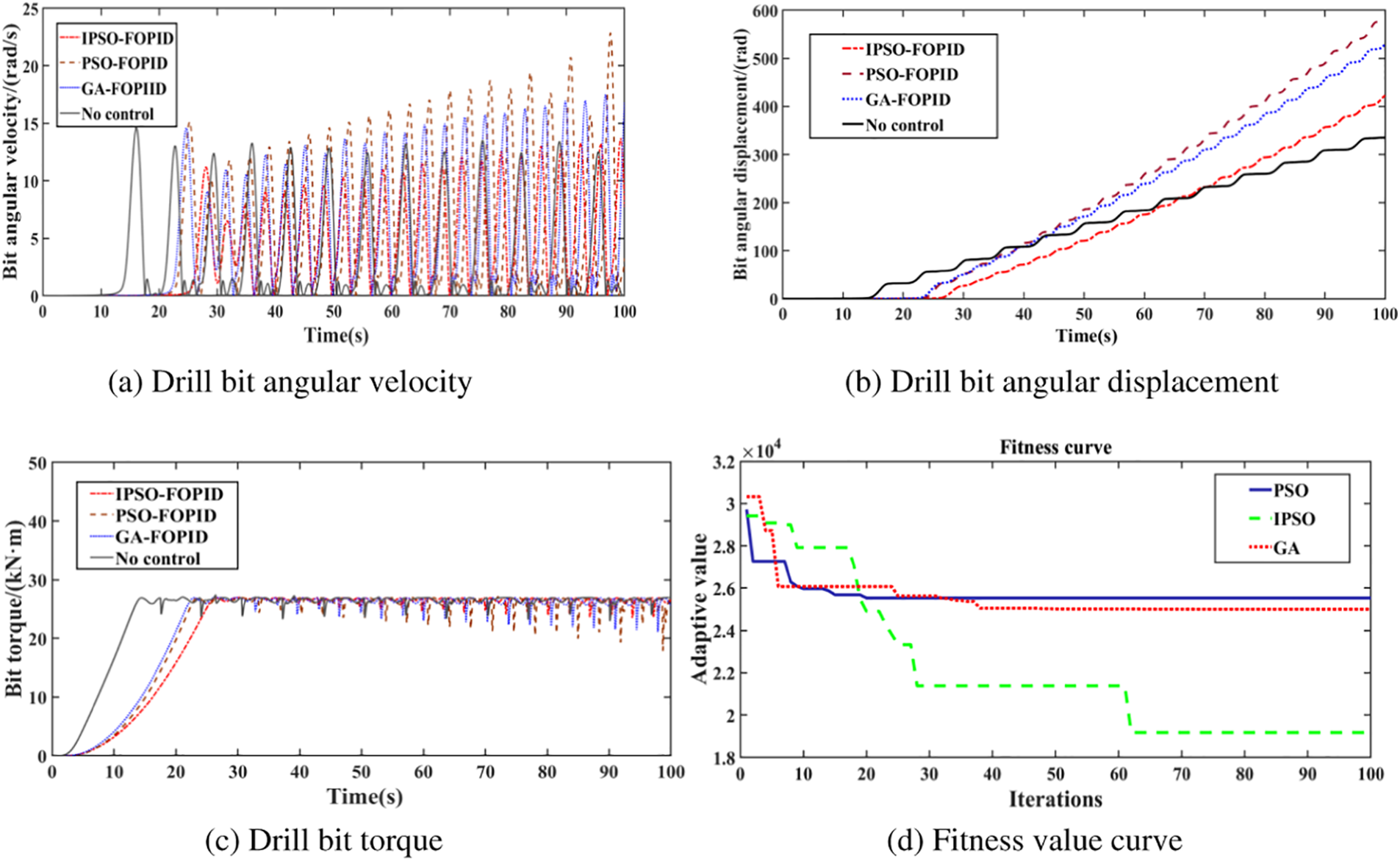
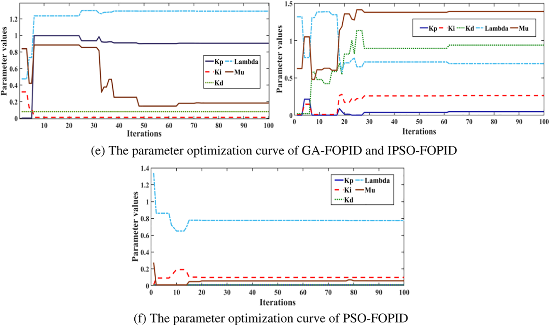
Figure 14: Control effect of GA-FOPID, GA-PID for serious stick slip of drill string
The optimization effect of each algorithm depends on the speed of the target search and the size of the search scope. When the search scope is large, the optimization speed will be reduced, and the search scope is too small, it is easy to fall into the local optimal solution. The advantage of using machine learning algorithm to optimize the controller is that it has the parameter memory function, which can speed up the optimization speed. Therefore, when using crowd optimization algorithm in machine learning algorithm, we should focus on improving its search speed and range ability to improve the control effect of the controller.
To solve the problem of FOPID parameter tuning, the combination of machine learning algorithm and FOPID control is used to maximize the adjustment effect of the controller. The optimization process avoids the occurrence of local optimal solutions and has better convergence during the iteration process.
The PSO algorithm is improved by using the multiplication and division operator strategy in arithmetic optimization algorithm to improve its control accuracy. The addition and subtraction strategies are used to reduce the dispersion of solutions, which is conducive to the full development of the population in the local range and strengthen the local optimization ability of the algorithm. The optimized PSO algorithm has better optimization effect than the GA algorithm.
When stick-slip vibration occurs without getting stuck, GA-FOPID, IPSO-FOPID, and PSO-FOPID controllers have a good suppression effect on stick-slip vibration. However, when severe stick-slip vibration (stuck) occurs, the controller cannot eliminate the stick-slip phenomenon of the drill string or release the stuck drill bit. At this time, it is necessary to adjust the main set rotary speed or WOB to make the drill string system get rid of severe stick-slip or stuck state, so that the controller can continue to play a role.
Although the machine learning algorithm can make the FOPID controller have a better performance in suppressing the drill string stick-slip vibration, the FOPID controller cannot get the drill string system out of the stuck state, and the machine learning algorithm is required to mark a large amount of data on the adjacent well to train the model.
The next step is to enhance the capabilities of the machine learning algorithm and the tuning capabilities of the controller, and consider more features and constraints (such as drilling parameters, geological conditions, etc.) to improve the ability of the machine learning model to predict drill string stcik-slip vibration. The interference observer is designed to eliminate the down hole interference signal and improve the regulation performance of the controller.
Acknowledgement: Authors acknowledge the National Natural Science Foundation of China (51974052) (51804061) and the Chongqing Basic Research and Frontier Technology Research Program (cstc2019jcyj-msxmX0199) for their funding.
Funding Statement: This research was funded by the National Natural Science Foundation of China (51974052) (51804061), the Chongqing Research Program of Basic Research and Frontier Technology (cstc2019jcyj-msxmX0199).
Author Contributions: The authors confirm contribution to the paper as follows: methodology: K.; writing-original draft: J.; methodology: M.; validation: H.; software: W.; formal analysis: L.
Availability of Data and Materials: The data used to support the findings of this study are available from the corresponding author upon request.
Conflicts of Interest: The authors declare that they have no conflicts of interest to report regarding the present study.
References
1. Brett, J. F. (1992). The genesis of torsional drill string vibrations. Journal of Petroleum Science and Engineering, 7(3), 168–174. https://doi.org/10.2118/23606-PA [Google Scholar] [CrossRef]
2. Feng, M., Chen, B., He, X. (2019). A review of stick-lip vibration control in oilwell drilling. IEEE Access, 7, 156158–156173. [Google Scholar]
3. Asgharzadeh, A., Bello, O., Baptista, N. R. P., Carvajal, C. A. P., Oppelt, J. (2016). Qualitative analysis of drill string torsional vibration preventive measures: Present status and future possible solution. SPE Nigeria Annual International Conference and Exhibition, Lagos, Nigeria. https://doi.org/10.2118/184381-MS [Google Scholar] [CrossRef]
4. Tian, J., Zhou, Y., Yang, L., Hu, S. (2020). Analysis of stick-slip reduction for a new torsional vibration tool based on PID control. Proceedings of the Institution of Mechanical Engineers, Part K: Journal of Multi-body Dynamics, 234(1), 82–94. https://doi.org/10.1177/1464419319876397 [Google Scholar] [CrossRef]
5. Tian, J., Wang, J., Zhou, S., Yang, Y., Dai, L. (2021). Study of stick-slip suppression and robustness to parametric uncertainty in drill strings containing torsional vibration tool using sliding-mode cont-rol. Proceedings of the Institution of Mechanical Engineers, Part K: Journal of Multi-Body Dynamics, 235(4), 653–667. https://doi.org/10.1177/14644193211045273 [Google Scholar] [CrossRef]
6. Depouhon, A., Detournay, E. (2014). Instability regimes and self-excited vibrations in deep drilling systems. Journal of Sound and Vibration, 333(7), 2019–2039. https://doi.org/10.1016/j.jsv.2013.11.011 [Google Scholar] [CrossRef]
7. Navarro-Lopez, E. M., Cortes, D. (2007). Avoiding harmful oscillations in a drill string through dynamical analysis. Journal of Sound and Vibration, 307(1/2), 152–171. https://doi.org/10.1016/j.jsv.2007.06.035 [Google Scholar] [CrossRef]
8. Richard, T., Germay, C., Detournay, E. (2004). Self-excited stick-slip oscillations of drill bits. Comptes Rendus Mécanique, 332(8), 619–626. https://doi.org/10.1016/j.crme.2004.04.004 [Google Scholar] [CrossRef]
9. Khulief, Y. A. (2010). Control engineering and stick-slip vibration in drilling. Journal of Petroleum Science and Engineering, 72(3–4), 199–211. https://doi.org/10.1016/j.petrol.2010.06.008 [Google Scholar] [CrossRef]
10. Smit, A. T. (1999). Using of optimal control techniques to dampen torsional drill strings vibrations, vol. 1999, pp. 20–45. Netherlands: University of Twente. https://doi.org/10.3990/1.9789036513529 [Google Scholar] [CrossRef]
11. Canudas-De-Wit, C., Rubio, F. R., Corchero, M. A. (2008). DOSKIL: A new mechanism for controlling stick-slip oscillations in oil well drill strings. IEEE Transactions on Control Systems Technology, 16(6), 1171–1191. https://doi.org/10.1109/TCST.2008.918365 [Google Scholar] [CrossRef]
12. Tucker, R. W., Wang, C. (1999). On the effective control of torsional vibrations of drill string systems. Journal of Sound and Vibration, 224(1), 101–122. https://doi.org/10.1006/jsvi.1999.2115 [Google Scholar] [CrossRef]
13. Yousefi, S., Arefi, M. M. (2020). Online optimization of fractional order PID controllers for stick-slip vibration suppression in drilling systems using a deep reinforcement learning approach. Journal of Petroleum Science and Engineering, 185, 106655. [Google Scholar]
14. Karkoub, M., Abdel-Magid, Y. L., Balachandran, B. (2009). Drill-string torsional vibration suppres- sion using GA optimized controllers. Journal of Canadian Petroleum Technology, 48(12), 32–38. https://doi.org/10.2118/09-12-32 [Google Scholar] [CrossRef]
15. Navarro-López, E. M., Cortés, D. (2007). Sliding-mode control of a multi-DOF oilwell drill string with stick-slip oscillations. American Control Conference, pp. 3837–3842. IEEENew York, NY, USA. https://doi.org/10.1109/ACC.2007.4282769 [Google Scholar] [CrossRef]
16. Tavakkoli-Moghaddam, R., Mohaghegh, M., Aghayari, R. (2020). A new fractional order PID controller for suppression of stick-slip vibrations in drilling systems: A combination of particle swarm optimization and bacterial foraging algorithm. Journal of Petroleum Science and Engineering, 185, 106536. [Google Scholar]
17. Lyu, M., Shen, S. (2014). The simulation and analysis of drill string stick-slip vibration. Journal of Southwest Petroleum University: Science & Technology Edition, 36(6), 150–159. https://doi.org/10.11885/j.issn.1674-5086.2013.02.22.02 [Google Scholar] [CrossRef]
18. Fu, M., Li, J., Wu, Y., S, S., A, Z. et al. (2019). State feedback and torque feed forward combined control system for suppressing drill-strings stick-slip vibration. Journal of Mechanical Engineering, 55(14), 1–10. https://doi.org/10.3901/JME.2019.14.001 [Google Scholar] [CrossRef]
19. Zhang, Q., Xu, S. (2020). Suppression of stick-slip vibration of drill string by fractional-order PID control. China Petroleum Machinery, 48(3), 44–50. https://doi.org/10.16082/j.cnki.issn.1001-4578.2020.03.008 [Google Scholar] [CrossRef]
20. Gad, S., Metered, H., Bassuiny, A., Abdel Ghany, A. M. (2017). Multi-objective genetic algorithm fracti-onal-order pid controller for semi-active magnetorheologically damped seat suspension. Journal of Vibration and Control, 23(8), 1248–1266. https://doi.org/10.1177/1077546315591620 [Google Scholar] [CrossRef]
21. Mohaghegh, M., Tavakkoli-Moghaddam, R., Khorasani, K. (2020). A novel multi-objective optimization algorithm based on the pareto dominance and reinforcement learning for the stick-slip vibration control problem. Journal of Petroleum Science and Engineering, 191, 107213. [Google Scholar]
22. Muftah, M. N., Faudzi, A. A. M., Sahlan, S., Shouran, M. (2022). Modeling and fuzzy FOPID controller tuned by PSO for pneumatic positioning system. Energies, 15(10), 3757. https://doi.org/10.3390/en15103757 [Google Scholar] [CrossRef]
23. Mohamed, M. E. A., Guo, Y. (2019). Separately excited DC motor speed tracking control using adaptive neuro-fuzzy inference system based on genetic algorithm particle swarm optimization and fuzzy auto-tuning PID. IOP Conference Series: Earth and Environmental Science, vol. 300, no. 4, 042114. IOP PublishingSan Francisco, USA. [Google Scholar]
24. Castro, F., Bernardes, N. D., Cuadros, M., Almeida, G. M. (2016). Comparison of fractional and integer PID controllers tuned by genetic algorithm. IEEE Transactions on Industrial Electronics, 63(3), 1821–1830. https://doi.org/10.1109/INDUSCON.2016.7874389 [Google Scholar] [CrossRef]
25. Ahmadi, A., Bahmani, M. (2019). A hybrid machine learning approach for real-time optimization of the drilling process to mitigate stick-slip vibrations. Journal of Petroleum Science and Engineering, 178, 300–310. [Google Scholar]
26. Pérez-Aracil, J., Camacho-Gómez, C., Pereira, E., Vaziri, V., Aphale, S. S. et al. (2021). Eliminating stick-slip vibrations in drill-strings with a dual-loop control strategy optimised by the CRO-SL algorithm. Mathematics, 9(13), 1526. https://doi.org/10.3390/math9131526 [Google Scholar] [CrossRef]
27. Khulief, Y. A., Al-Sulaiman, F. A., Bashmal, S. (2007). Vibration analysis of drill strings with self-excited stick-slip oscillations. Journal of Sound and Vibration, 299(3), 540–558. https://doi.org/10.1016/j.jsv.2006.06.035 [Google Scholar] [CrossRef]
28. Lin, Y. Q., Wang, Y. H. (1991). Stick-slip vibration of the drill strings. Journal of Manufacturing Science and Engineering, 113(1), 38–43. https://doi.org/10.1016/j.jsv.2006.06.065 [Google Scholar] [CrossRef]
29. Lopez, E. N., Navarro-Lopez, E. M., Suarez, R. (2004). Modelling and analysis of stick-slip behavior in a drill string under dry frictions. Congreso de la AMCA 2004: Congress of the Mexican Association of Computational Mechanics, pp. 1–10. Mexico City, Mexico. https://doi.org/10.1016/j.jsv.2014.08.001 [Google Scholar] [CrossRef]
30. Wit, C., Olsson, H., Åström, K. J., Lischinsky, P. (1995). A new model for control of systems with friction. IEEE Transactions on Control Systems Technology, 3(3), 419–425. https://doi.org/10.1109/9.376054 [Google Scholar] [CrossRef]
31. Derbal, M., Gharib, M., Refaat, S. S., Palazzolo, A., Sassi, S. (2021). Fractional-order controllers for stick-slip vibration mitigation in oil well drill-strings. Journal of Low Frequency Noise, Vibration and Active Control, 40(3), 1571–1584. https://doi.org/10.1177/1461348420984040 [Google Scholar] [CrossRef]
32. Kanagaraj, N., Jha, V. N. (2021). Design of an enhanced fractional order PID controller for a class of second-order system. COMPEL-The International Journal for Computation and Mathematics in Electrical and Electronic Engineering, 40(3), 579–592. https://doi.org/10.1108/COMPEL-08-2020-0267 [Google Scholar] [CrossRef]
33. Chen, M., Gao, Y. (2019). Parameter tuning of fractional order PID controller based on deep reinforcement learning for drilling systems. ISA Transactions, 96, 450–457. [Google Scholar]
34. Xue, D., Zhao, C., Chen, Y. (2006). A modified approximation method of fractional order system. 2006 International Conference on Mechatronics and Automation (ICMA 2006), vol. 3, pp. 1043–1048. IEEE, Luoyang, China. https://doi.org/10.1109/ICMA.2006.257697 [Google Scholar] [CrossRef]
35. Abiyev, R. (2014). Design of fractional order controllers using genetic algorithms. British Journal of Mathematics & Computer Science, 4(18), 2594–2602. https://doi.org/10.9734/BJMCS/2014/10447 [Google Scholar] [CrossRef]
36. Pour, M. S., Parsa, S. (2019). Stick-slip vibration suppression in drilling systems using a new method based on a fuzzy fractional order PID controller optimized by a genetic algorithm. Journal of Petroleum Science and Engineering, 180, 521–535. [Google Scholar]
37. Srinivas, M., Patnaik, L. M. (1994). Adaptive probabilities of crossover and mutation in genetic algorithms. IEEE Transactions on Systems,Man,and Cybernetics, 24(4), 656–667. https://doi.org/10.1109/21.286374 [Google Scholar] [CrossRef]
38. Chen, C., Hu, L., Ma, Y., Zhang, Y., Li, Y. (2016). Improved genetic algorithm for optimal fractional order PID controller. Journal of Xi’an Technological University, 36(6), 510–516. https://doi.org/10.1081/CEH-200044273 [Google Scholar] [CrossRef]
39. Zhang, X., Zhong, C. Q. (2018). Fractional order PI∼λD∼μ controller design based on quantum particle swarm optimization. Control Engineering of China, 25(3), 493–498. https://doi.org/10.14107/j.cnki.kzgc.1001-9669.2018.03.067 [Google Scholar] [CrossRef]
40. Abualigah, L., Diabat, A., Mirjalili, S., Faris, H., Aljarah, I. (2021). The arithmetic optimization algorithm. Computer Methods in Applied Mechanics and Engineering, 376, 113610. https://doi.org/10.1016/j.cma.2021.113610 [Google Scholar] [CrossRef]
41. Teng, X., Di, Q. F., Li, N., Chen, F., Zhou, B. (2017). Measurement and analysis of stick-slip characteristics of drill string in ultra-deep wells. Petroleum Drilling Techniques, 45(2), 32–39. https://doi.org/10.11911/syztjs [Google Scholar] [CrossRef]
Cite This Article
 Copyright © 2023 The Author(s). Published by Tech Science Press.
This work is licensed under a Creative Commons Attribution 4.0 International License , which permits unrestricted use, distribution, and reproduction in any medium, provided the original work is properly cited.
 Downloads
 Citation Tools