
 Submit a Paper
 Propose a Special lssue
 Open Access
ARTICLE

Development and Application of a Power Law Constitutive Model for Eddy Current Dampers
1 School of Civil Engineering and Architecture, Xiamen University of Technology, Xiamen, 361024, China
2 Hunan Provincial Key Laboratory of Wind and Bridge Engineering, Hunan University, Changsha, 410082, China
3 Fujian Provincial Key Laboratory of Wind Disaster and Engineering, Xiamen University of Technology, Xiamen, 361024, China
4 State Key Laboratory of Bridge Engineering Safety and Resilience, Hunan University, Changsha, 410082, China
* Corresponding Author: Zhouquan Feng. Email:
Computer Modeling in Engineering & Sciences 2024, 138(3), 2403-2419. https://doi.org/10.32604/cmes.2023.031260
Received 26 May 2023; Accepted 18 August 2023; Issue published 15 December 2023
 View Full Text
 Download PDF
Abstract
Eddy current dampers (ECDs) have emerged as highly desirable solutions for vibration control due to their exceptional damping performance and durability. However, the existing constitutive models present challenges to the widespread implementation of ECD technology, and there is limited availability of finite element analysis (FEA) software capable of accurately modeling the behavior of ECDs. This study addresses these issues by developing a new constitutive model that is both easily understandable and user-friendly for FEA software. By utilizing numerical results obtained from electromagnetic FEA, a novel power law constitutive model is proposed to capture the nonlinear behavior of ECDs. The effectiveness of the power law constitutive model is validated through mechanical property tests and numerical seismic analysis. Furthermore, a detailed description of the application process of the power law constitutive model in ANSYS FEA software is provided. To facilitate the preliminary design of ECDs, an analytical derivation of energy dissipation and parameter optimization for ECDs under harmonic motion is performed. The results demonstrate that the power law constitutive model serves as a viable alternative for conducting dynamic analysis using FEA and optimizing parameters for ECDs.Keywords
Passive energy dissipation devices have garnered significant attention over the past few decades [1,2]. The use of dampers for passive control has been proven to be an effective strategy for improving the dynamic response of various civil structures, such as buildings [3], bridges [4], wind turbines [5] and solar towers [6]. Numerous energy dissipation devices, including viscous dampers [7,8], magneto-rheological dampers [9,10], pounding dampers [11], friction dampers [12,13], and viscous inerter dampers [14] have been developed.
In recent years, eddy current dampers (ECDs) have emerged as a promising passive control device in the field of civil engineering. ECD offers high fatigue resistance and low starting friction, thanks to their non-contact damping force generation mechanism [15,16]. Notable advancements and refinements in the ECD structure, such as the introduction of ball screw and novel magnet matrix arrangement, have expanded their applicability across various engineering domains. For instance, Wang et al. [17] proposed an ECD system to mitigate the multi-mode high-order vibration of ultra-long stay cables, and field test results demonstrated the system’s effective suppression of cable vibrations. Lu et al. [18] conducted laboratory and field tests on a giant eddy current tune mass damper installed on a high-rise landmark building in China, confirming its satisfactory control performance. Additionally, Zhang et al. [19] designed a rotary ECD to alleviate the longitudinal seismic response of a suspension bridge, with mechanical property tests revealing a maximum damping force of 500 kN.
Developing a constitutive model that accurately characterizes the damping force-velocity relationship is essential for dynamic analysis of structures equipped with ECDs. ECDs exhibit distinct damping behavior compared to traditional viscous dampers. They demonstrate nearly linear damping characteristics at low velocities but exhibit nonlinearity at high velocities [20]. Currently, the widely used constitutive model for ECDs is the one proposed by Wouterse, which is based on test results of eddy current disc brakes with iron pole shoes [21]. The parameters in the Wouterse constitutive model possess clear physical interpretations, enabling easy comprehension by researchers. The accuracy of the Wouterse constitutive model has been validated by researchers. For example, Li et al. [22,23] employed the Wouterse constitutive model to characterize the damping behavior of rack and gear ECD mechanisms, and the theoretical and mechanical property test results exhibited good agreement with the Wouterse constitutive model.
However, the Wouterse constitutive model poses a significant drawback when performing finite element analysis (FEA) for dynamic response. Unlike the power law constitutive model used for common viscous dampers, which can be directly simulated using existing elements in FEA software, the Wouterse constitutive model for ECD constitutive behavior cannot be directly implemented. As a result, the utilization of the Wouterse constitutive model hinders the wider adoption of ECDs.
To address this limitation, this study aims to propose a new constitutive model that is not only easy to comprehend but also compatible with FEA software. Firstly, a novel power law constitutive model is derived based on numerical results obtained from electromagnetic FEA. Secondly, a comprehensive assessment is conducted through mechanical property testing and numerical seismic analysis to validate the power law constitutive model’s capability to characterize the nonlinear behavior of ECDs. Thirdly, a detailed description is provided regarding the application process of the power law constitutive model in the widely used FEA software, ANSYS. Finally, an analytical derivation of ECD’s energy dissipation and subsequent parameter optimization are performed to facilitate dynamic analysis of ECDs, thereby enhancing their overall effectiveness.
2 Power Law Constitutive Model of ECD
In this section, a novel power law constitutive model to characterize the constitutive behavior of ECDs is proposed. The power law constitutive model is derived from the numerical results obtained through electromagnetic finite element simulation. Unlike the Wouterse constitutive model, the power law constitutive model incorporates four power law functions, enabling a more convenient and efficient simulation of ECDs’ constitutive behavior in finite element software.
Fig. 1 illustrates a typical rotary axial ECD, comprising two primary components: the ball screw assembly and the eddy current damping generator. The ball screw assembly comprises a ball screw drive pair, a stator and a rotor in which the stator and the rotor are made from ferromagnet materials. On the other hand, the eddy current damping generator is composed of permanent magnets and a conductive cylinder, arranged on the rotor and the stator, respectively.
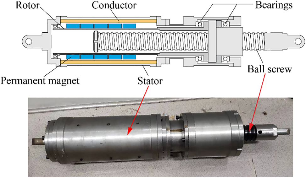
Figure 1: Schematic and prototype of the rotary axial ECD
ECD is a kind of velocity-dependent nonlinear damper. At this stage, its constitutive behavior, namely the damping force-velocity relationship, is often characterized by the Wouterse constitutive model as follows:
where
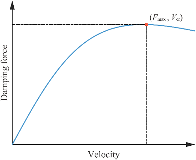
Figure 2: Damping force-velocity relationship of ECDs
Nevertheless, the Wouterse constitutive model expression differs from the power law constitutive model commonly used to simulate the mechanical properties of viscous dampers. The constitutive model of a nonlinear viscous damper can be expressed as
where
2.2 Derivation of the Power Law Constitutive Model
In order to improve the efficiency of FEM analysis with ECDs, we constructed a power law constitutive model as same as the one of viscous dampers. The parameters
A normalization process is conducted to retain the parameters
where
A curve fitting method is employed to determine the values of the constants
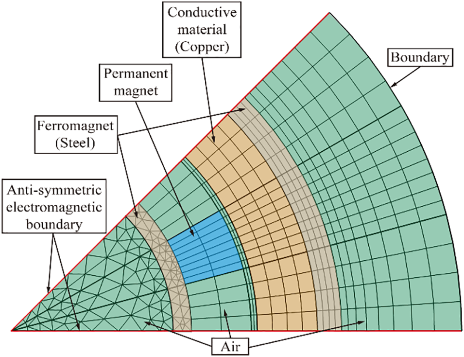
Figure 3: Schematic of 2D finite element meshing
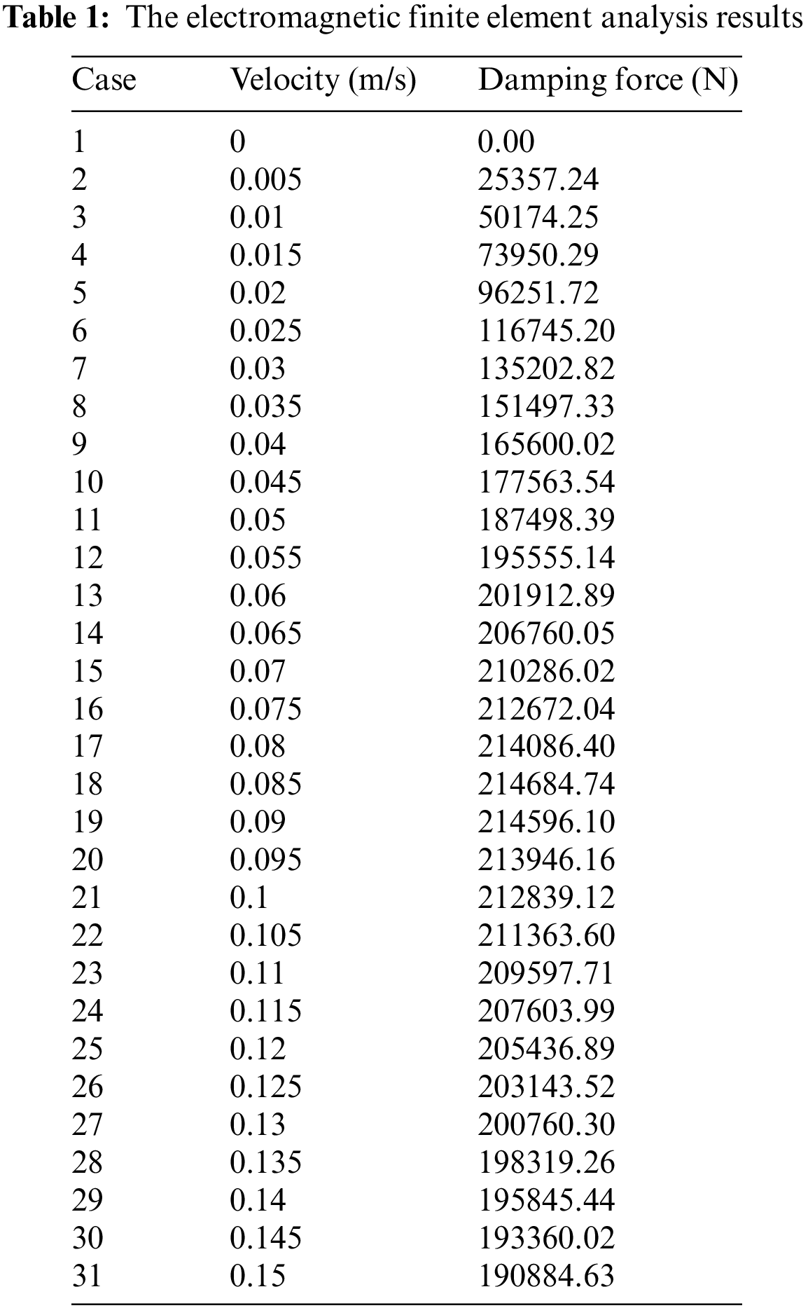
The electromagnetic finite element analysis results are shown in Table 1.
Additionally, to ensure the mechanical properties of parameters
where
Genetic algorithm is employed to solve the optimization problem. The expression of the power law constitutive model for the constitutive behavior of ECD was obtained as follows:
The power law constitutive model damping force-velocity relationship curve is plotted in Fig. 4, and the Wouterse constitutive model relationship curve also is fitted and presented in Fig. 4 for comparison. It can be observed that the power law constitutive behavior model matches considerably well with the target curve. The coefficient of determination (denoted R2, normally ranges from 0 to 1) is employed to assess the degree of agreement for two curves. The more closely the two curves match, the closer the value of R2 is to one. The R-square value of the Wouterse constitutive model for FEM data in Fig. 4 is 0.9995, which indicates a hiah-level coincidence of the power law constitutive model for the constitutive behavior of ECD.
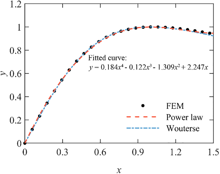
Figure 4: Fitted curve of the power law constitutive model of ECD
Substitute
It can be observed from Eq. (6) that the power law constitutive model is still determined by the parameters
In conclusion, the power law constitutive model was demonstrated to be able to express the nonlinear damping behavior of ECDs. The parameters
3 Validation of Power Law Constitutive Behavior Model of ECD
This section encompasses the validation of the power law constitutive behavior model through two approaches. Firstly, a mechanical property test of a rotary axial ECD was performed to validate the model’s accuracy. Secondly, a numerical analysis of a single-degree-of-freedom (SDOF) system supplemented with an ECD, subjected to seismic excitations, was conducted using the Runge-Kutta method. This numerical analysis serves as an additional validation of the power law constitutive model’s effectiveness.
A mechanical property test was performed on the rotary axial ECD, as depicted in Fig. 5. The ECD was integrated into a dynamic test system, with one end fixed and the other end connected to an actuator. The test involved subjecting the ECD to sinusoidal displacement excitations at various amplitudes and frequencies. This study encompassed a total of nine cases, each with different displacement amplitudes and frequencies.
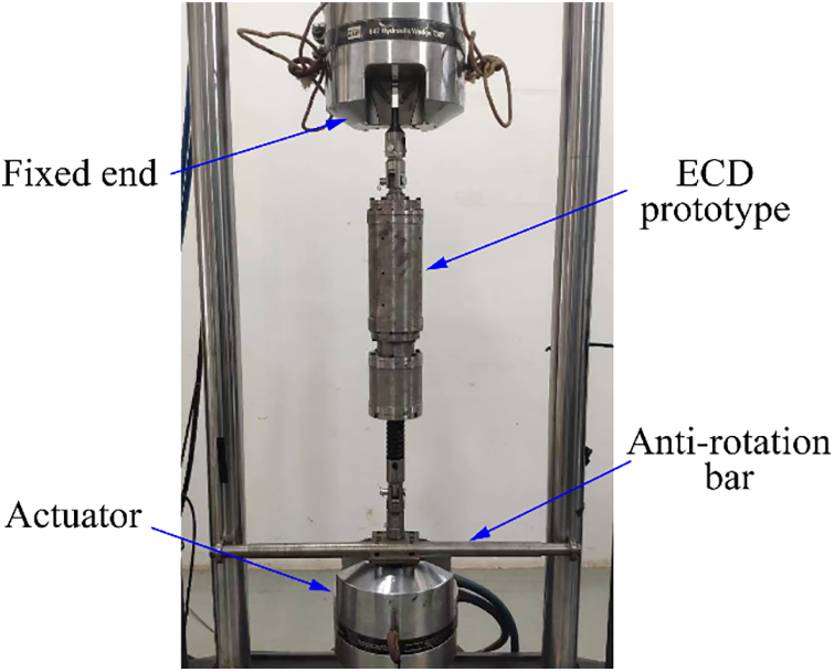
Figure 5: Mechanical property test of the rotary axial ECD
As shown in Fig. 6a, the damping force amplitude and the corresponding velocity amplitude of each case were recorded as circle marker. The fitted curve of the power law constitutive model was obtained and presented in Fig. 6a, and the curve of Wouterse constitutive model was also plotted as a comparison. The R-square value of the power law constitutive model for test data is 0.9932, while the R-square value of the Wouterse constitutive model for test data is 0.9901. This suggests that the power law constitutive model characterizes the nonlinear damping behavior of ECD properly. Furthermore, the hysteresis loops of the case with the velocity amplitude 60 mm/s are presented in Fig. 6b. It can be seen that the hysteresis loops directly obtained from the Eq. (6) match very well with the one recorded in the mechanical property test.
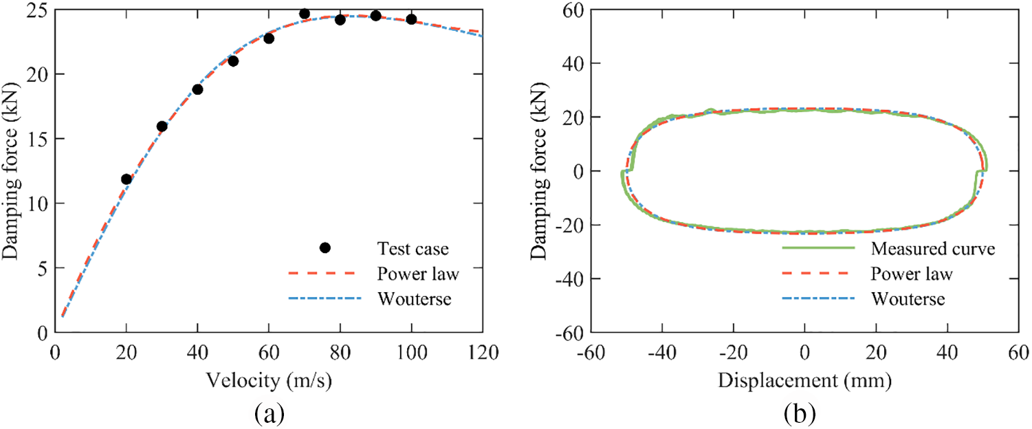
Figure 6: Mechanical property test of the rotary axial ECD. (a) Damping force-velocity relationship curve; (b) Hysteresis loops of the velocity amplitude 60 mm/s
The mechanical property test results indicate that the power law constitutive behavior model can reflect the nonlinear damping performance of ECD accurately.
A linear elastic SDOF system supplemented with a nonlinear ECD subjected to ground motion is proposed to validate the accuracy of the power law constitutive model in numerical analysis. The schematic is plotted in Fig. 7. The motion governing equation of the SDOF-ECD system can be written as
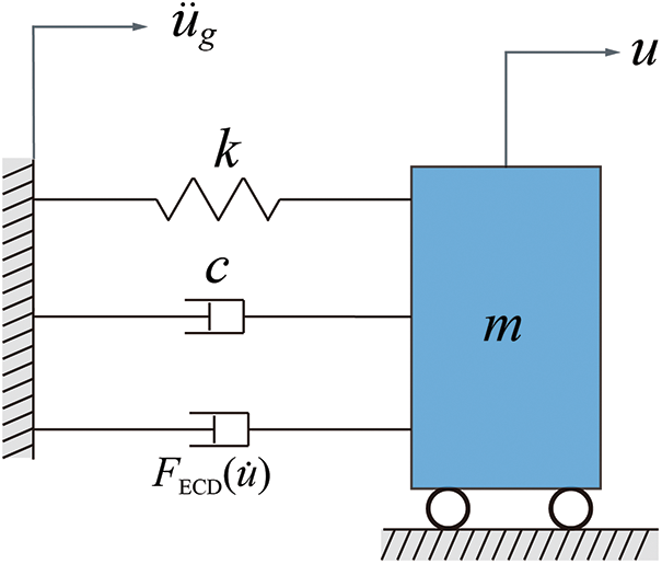
Figure 7: Schematic of the SDOF-ECD system
where m, k, and c are the mass, elastic stiffness, and linear viscous damping coefficient, respectively.
The Elcentro wave presented in Fig. 8 was adopted as seismic excitation in this section. The peak ground acceleration was taken to 2 m/s2. The dynamic analysis was conducted utilizing the Runge-Kutta algorithm in the numerical analysis software Matlab. The dynamic response of the power law constitutive model was obtained and compared with the response of the Wouterse constitutive model.
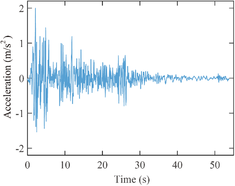
Figure 8: Time history of elcentro wave
It is noteworthy that the curve fitting process of the power law constitutive model was conducted with the dimensionless velocity
In this example, the parameter
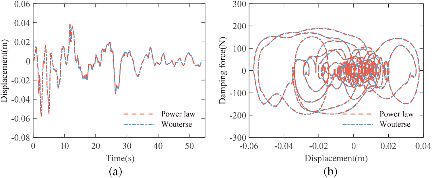
Figure 9: Response comparison of the power law constitutive model and Wouterse constitutive model (a) Displacement responses history curve; (b) Hysteresis loops
In conclusion, the power law constitutive model is proved to be capable to characterize the nonlinear damping behavior of ECD accurately based on the test and numerical validation.
4 Application of Power Law Constitutive Model in FEA Software
In this section, a detailed description of the application process of the power law constitutive model in FEA software is proposed. the process is conducted based on the common software ANSYS. The SDOF-ECD system example in Section 3.2 is still taken as the study case.
The simulation of power law constitutive model of ECD can be directly conducted using one of the existing elements, making it a straightforward process. However, utilizing the Wouterse constitutive model in ANSYS proves to be considerably more complex. Customization becomes necessary for implementing the Wouterse constitutive model, as depicted in Fig. 10. This customization involves configuring the FORTRAN environment and modifying the User Programmable Features (UPFs), which demands significant time and effort. Additionally, since many FEA software do not provide open access for customization, the Wouterse constitutive model cannot be effectively utilized in ECD finite element analysis.
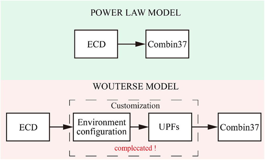
Figure 10: Technology roadmaps of simulation process of power law constitutive model and Wouterse constitutive model
The Combin37 element in ANSYS was adopted to simulate the power law constitutive model of ECD. This element is commonly used to simulate the damping behavior of viscous dampers. When the key option 9 of the Combin37 was taken to 0, the RVMOD formula of the element can be expressed as
where
Apparently, the power law constitutive model can characterize the nonlinear damping behavior of ECD successfully for sharing the same form of expression with the constitutive model of the viscous damper. Two Combin37 elements are adopted to simulate the mechanical property of ECD. According to Eq. (6), the real constants
By connecting two Combin37 elements in parallel, we can realize the simulation of the power law constitutive model of ECD. Thus, The damping behavior of ECD can be characterized conveniently and efficiently in FEA software.
4.2 Dynamic Response Analysis in FEA Software
In this section, we present an example of an SDOF system model. The seismic response of the SDOF system was obtained using ANSYS and compared with the numerical results obtained using the Runge-Kutta method. Through this comparison, the accuracy of the power law constitutive model for ECDs is confirmed, validating its effectiveness in predicting the seismic response of the system.
The same SDOF system in Fig. 7 was established in ANSYS. The seismic response analysis was conducted considering the SDOF system subjected to the Elcentro wave of Fig. 8. The displacement history curve is plotted in Fig. 11. The green dash-dot line represents the displacement response obtained by FEM, and the red dashed line represents the displacement response of power law constitutive model obtained by Runge-Kutta method in the numerical analysis software Matlab. It can be seen from Fig. 11 that the displacement history curves match very well. The power law constitutive model is simulated precisely in ANSYS with the original Combin37 element.
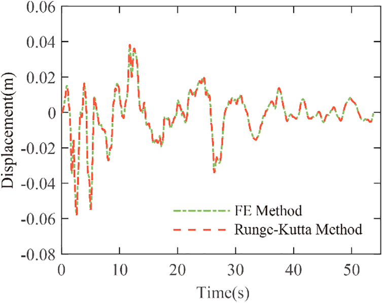
Figure 11: Displacement response comparison between FEM and Runge-Kutta method
To examine the computational efficiency of the two models, we performed the seismic response analysis example from Section 4.2 on the same computer. The power law constitutive model case took 308 s, while the Wouterse constitutive model case took 320 s. This suggests that the power law constitutive model demonstrates slightly better computational efficiency than the Wouterse constitutive model.
As a result, the nonlinear damping behavior of ECD is characterized easily by the power law constitutive model in FEA software. The power law constitutive model of ECD is a good choice for achieving an accurate and efficient analysis when considering vibration control FEA problems with ECD in this stage.
5 Energy Dissipation Analysis Based on Power Law Constitutive Model
The performance of dampers in reducing vibrations is closely related to their energy dissipation capacity. In this section, we analyze the energy dissipation capacity of ECDs using the power law constitutive model. We derive an analytical expression for the energy dissipated by the ECD during a cycle of harmonic motion. Furthermore, based on the analytical conclusions obtained from the power law constitutive model, we optimize the critical velocity parameter of the ECD to enhance its energy dissipation capabilities.
5.1 Energy Dissipation Capacity under Harmonic Motion
The energy dissipation capacity under harmonic motion is usually considered the key indicator of the vibration control performance of dampers. The energy consumption formula of the ECD during a cycle of harmonic motion was derived based on the power law constitutive model.
The ECD is assumed to be subjected to harmonic motion
The detailed formula derivation is shown in Appendix A. It can be seen that
5.2 Energy Consumption Formula Validation
The accuracy validation of Eq. (11) is conducted by comparing it with the energy consumption formula based on Wouterse constitutive model. For ECD governed by Wouterse constitutive model, the energy dissipated by the ECD during a cycle of harmonic motion can be expressed as [24]
It should be noted that the maximum velocity of the harmonic motion
and
Through observing the mathematical structure of Eqs. (13) and (14), the accuracy validation can be conducted by comparing the term
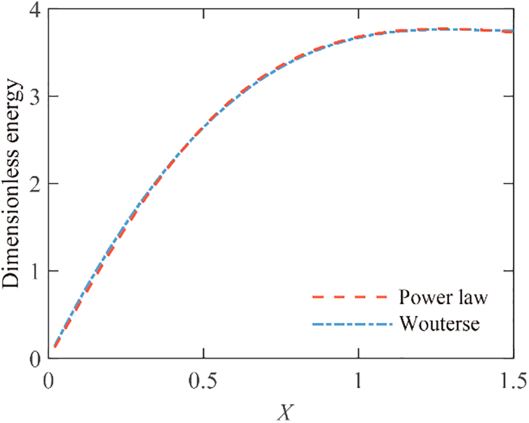
Figure 12: Dimensionless energy curves of power law constitutive model and Wouterse constitutive model
5.3 ECD Parameter Optimization Based on Power Law Constitutive Model
The equivalent linearization method is a very common damper parameters optimization method. In this section, the ECD parameter optimization is conducted based on the equivalent linearization method. The energy dissipated by the linear viscous damper is employed as a reference.
The energy dissipated by the linear viscous damper during a cycle of harmonic motion can be expressed as
where
Considering the ECD is subjected to the same cycle of harmonic motion, there is no harm in defining a proportional factor
where
Apparently, the term
Denote
In this way, the optimization of the parameter critical velocity
A novel power law constitutive model for ECD was proposed based on the numerical result obtained from electromagnetic finite element simulation. This model was specifically designed to enable convenient and efficient simulation of the constitutive behavior of ECDs in finite element software. The power law constitutive model consists of four power law functions, allowing for straightforward implementation in FEA software.
The effectiveness of the power law constitutive model in characterizing the nonlinear damping behavior of ECDs and expressing the damping force-velocity relationship was confirmed. The parameters
A detailed application process of the power law constitutive model in FEA software was presented, specifically focusing on the use of the Combin37 element in ANSYS. By connecting two Combin37 elements in parallel, the simulation of the power law constitutive model for ECDs can be realized. The results indicate that the power law constitutive model enables easy characterization of the nonlinear damping behavior of ECDs in FEA analysis.
The energy dissipated by the ECD under a cycle of harmonic motion is derived analytically and subsequently validated. Moreover, the optimization of the critical velocity parameter of the ECD was achieved based on analytical conclusions derived from the power law constitutive model. It was determined that when the ratio of maximum velocity of the harmonic motion to the parameter
Overall, the power law constitutive model proves to be a suitable alternative for conducting FEA dynamic analysis and optimizing the parameters of ECDs, offering improved convenience and accuracy in these applications.
Acknowledgement: The authors would like to express gratitude to the editors and reviewers for their valuable comments.
Funding Statement: This research was supported by the National Natural Science Foundation of China (Nos. 52178284 and 51708203), Natural Science Foundation of Hunan Province (No. 2021JJ30106), the Opening Fund of Key Laboratory for Wind Engineering and Bridge Engineering of Hunan Province (No. 2022ZDK001), the Science and Technology Research Project of Xiamen University of Technology (YKJ23005R).
Author Contributions: The authors confirm their contributions to the paper as follows: data analysis and writing by Longteng Liang; conceptualization and review by Zhouquan Feng; data collection by Hongyi Zhang and Changzhao Qian; supervision by Zhengqing Chen. All authors critically reviewed the results and approved the final version of the manuscript.
Availability of Data and Materials: Not applicable.
Conflicts of Interest: The authors declare that they have no conflicts of interest to report regarding the present study.
References
1. Soong, T. T., Dargush, G. F. (1997). Passive energy dissipation systems in structural engineering. UK: Wiley. [Google Scholar]
2. Chopra, A. K. (2001). Dynamics of structures: Theory and applications to earthquake engineering. Upper Saddle River, NJ: Prentice Hall. [Google Scholar]
3. Javidan, M. M., Kim, J. (2019). Seismic retrofit of soft-first-story structures using rotational friction dampers. Journal of Structural Engineering, 145(12), 04019162. [Google Scholar]
4. Ben-Israel, N. I., Lavan, O. (2023). Topology and sizing optimization of truss-like pedestrian bridges with viscous dampers and inerters. Journal of Structural Engineering, 149(6), 04023054. [Google Scholar]
5. Bernuzzi, C., Crespi, P., Montuori, R., Nastri, E., Simoncelli, M. et al. (2021). Resonance of steel wind turbines: Problems and solutions. Structures, 32(3), 65–75. [Google Scholar]
6. Liu, M., Li, S., Wu, T., Li, Y., Meng, H. (2021). Eddy-current tuned mass dampers for mitigation of wind-induced response of the Noor III solar tower: Design, installation, and validation. Journal of Structural Engineering, 147(12), 05021009. [Google Scholar]
7. Guo, T., Liu, J., Zhang, Y., Pan, S. (2015). Displacement monitoring and analysis of expansion joints of long-span steel bridges with viscous dampers. Journal of Bridge Engineering, 20(9), 04014099. [Google Scholar]
8. Lin, W. H., Chopra, A. K. (2003). Earthquake response of elastic single-degree-of-freedom systems with nonlinear viscoelastic dampers. Journal of Engineering Mechanics, 129(6), 597–606. [Google Scholar]
9. Li, H., Liu, M., Li, J., Guan, X., Ou, J. (2007). Vibration control of stay cables of the Shandong Binzhou yellow river highway bridge using magnetorheological fluid dampers. Journal of Bridge Engineering, 12(4), 401–409. [Google Scholar]
10. Chen, Z. Q., Wang, X. Y., Ko, J. M., Ni, Y. Q., Spencer, B. F. et al. (2004). MR damping system for mitigating wind-rain induced vibration on Dongting Lake cable-stayed bridge. Wind and Structures, 7(5), 293–304. [Google Scholar]
11. Wang, W., Wang, X., Hua, X., Song, G. B., Chen, Z. Q. (2018). Vibration control of vortex-induced vibrations of a bridge deck by a single-side pounding tuned mass damper. Engineering Structures, 173(6), 61–75. [Google Scholar]
12. Guo, W., Zeng, C., Gou, H., Hu, Y., Xu, H. et al. (2019). Rotational friction damper’s performance for controlling seismic response of high speed railway bridge-track system. Computer Modeling in Engineering & Sciences, 120(3), 491–515. [Google Scholar]
13. Liang, L., Feng, Z., Xu, Y., Chen, Z., Liang, L. (2023). A parallel scheme of friction dampers and viscous dampers for girder-end longitudinal displacement control of a long-span suspension bridge under operational and seismic conditions. Buildings, 13(2), 412. [Google Scholar]
14. Gao, H., Wang, H., Li, J., Wang, Z., Liang, R. et al. (2021). Optimum design of viscous inerter damper targeting multi-mode vibration mitigation of stay cables. Engineering Structures, 226(11), 111375. [Google Scholar]
15. Huang, Z. W., Hua, X. G., Chen, Z. Q., Niu, H. W. (2018). Modeling, testing, and validation of an eddy current damper for structural vibration control. Journal of Aerospace Engineering, 31(5), 04018063. [Google Scholar]
16. Pu, Y., Huang, Z., Zhang, H., Hua, X., Xu, Y. (2023). Shock vibration control of SDOF systems with tubular linear eddy current dampers. Applied Sciences, 13(4), 2226. [Google Scholar]
17. Wang, Y., Chen, Z., Yang, C., Liu, Z., He, J. et al. (2022). A novel eddy current damper system for multi-mode high-order vibration control of ultra-long stay cables. Engineering Structures, 262(5), 114319. [Google Scholar]
18. Lu, X., Zhang, Q., Weng, D., Zhou, Z., Wang, S. et al. (2017). Improving performance of a super tall building using a new eddy-current tuned mass damper. Structural Control and Health Monitoring, 24(3), e1882. [Google Scholar]
19. Zhang, H. Y., Chen, Z. Q., Hua, X. G., Huang, Z. W., Niu, H. W. et al. (2020). Design and dynamic characterization of a large-scale eddy current damper with enhanced performance for vibration control. Mechanical Systems and Signal Processing, 145(3), 106879. [Google Scholar]
20. Anwar, S., Stevenson, R. C. (2006). Torque characteristics analysis of an eddy current electric machine for automotive braking applications. American Control Conference, 2006, 6. [Google Scholar]
21. Wouterse, J. H. (1991). Critical torque and speed of eddy current brake with widely separated soft iron poles. IEE Proceedings B (Electric Power Applications), 138(4), 153–158. [Google Scholar]
22. Li, S., Li, Y., Mao, W., Wang, J., Chen, Z. (2022). A novel 500 kN axial eddy current damper using rack and gear mechanism: Design, testing, and evaluation. Structural Control and Health Monitoring, 29(10), e3022. [Google Scholar]
23. Li, S., Li, Y., Wang, J., Chen, Z. (2022). Theoretical investigations on the linear and nonlinear damping force for an eddy current damper combining with rack and gear. Journal of Vibration and Control, 28(9–10), 1035–1044. [Google Scholar]
24. Liang, L., Feng, Z., Chen, Z. (2019). Seismic control of SDOF systems with nonlinear eddy current dampers. Applied Sciences, 9(16), 3427. [Google Scholar]
The mathematic proofs of Eq. (11) are shown in this appendix section. The energy dissipation of ECD under a cycle of harmonic excitation can be written as
Substitute
Substitute Eqs. (A2) to (A5) into Eq. (A1), it becomes
The mathematic proofs of the optimal design of ECD based on the power law constitutive model are shown in this appendix. The derivative and second derivative of
Let
Therefore, when
Cite This Article
 Copyright © 2024 The Author(s). Published by Tech Science Press.
This work is licensed under a Creative Commons Attribution 4.0 International License , which permits unrestricted use, distribution, and reproduction in any medium, provided the original work is properly cited.
 Downloads
 Citation Tools