
 Submit a Paper
 Propose a Special lssue
 Open Access
ARTICLE
System Modeling and Deep Learning-Based Security Analysis of Uplink NOMA Relay Networks with IRS and Fountain Codes
1 Data Science Laboratory, Faculty of Information Technology, Ton Duc Thang University, Ho Chi Minh City, 70000, Vietnam
2 Faculty of Telecommunications 2, Posts and Telecommunications Institute of Technology, Ho Chi Minh City, 70000, Vietnam
3 Department of Electrical and Electronics Engineering, Faculty of Engineering, University of Lagos, Akoka, Lagos, 100213, Nigeria
4 Department of Software and Communications Engineering, Hongik University, Sejong, 30016, Republic of Korea
* Corresponding Author: Byung-Seo Kim. Email:
(This article belongs to the Special Issue: Artificial Intelligence for 6G Wireless Networks)
Computer Modeling in Engineering & Sciences 2025, 144(2), 2521-2543. https://doi.org/10.32604/cmes.2025.066669
Received 14 April 2025; Accepted 18 July 2025; Issue published 31 August 2025
 View Full Text
 Download PDF
Abstract
Digital content such as games, extended reality (XR), and movies has been widely and easily distributed over wireless networks. As a result, unauthorized access, copyright infringement by third parties or eavesdroppers, and cyberattacks over these networks have become pressing concerns. Therefore, protecting copyrighted content and preventing illegal distribution in wireless communications has garnered significant attention. The Intelligent Reflecting Surface (IRS) is regarded as a promising technology for future wireless and mobile networks due to its ability to reconfigure the radio propagation environment. This study investigates the security performance of an uplink Non-Orthogonal Multiple Access (NOMA) system integrated with an IRS and employing Fountain Codes (FCs). Specifically, two users send signals to the base station at separate distances. A relay receives the signal from the nearby user first and then relays it to the base station. The IRS receives the signal from the distant user and reflects it to the relay, which then sends the reflected signal to the base station. Furthermore, a malevolent eavesdropper intercepts both user and relay communications. We construct mathematical equations for Outage Probability (OP), throughput, diversity evaluation, and Interception Probability (IP), offering quantitative insights to assess system security and performance. Additionally, OP and IP are analyzed using a Deep Neural Network (DNN) model. A deeper comprehension of the security performance of the IRS-assisted NOMA system in signal transmission is provided by Monte Carlo simulations, which are also carried out to confirm the theoretical conclusions.Keywords
Due to its improved spectrum efficiency, Non-Orthogonal Multiple Access (NOMA) is crucial for sixth-generation (6G) and future wireless networks [1]. NOMA significantly enhances user connection and spectrum efficiency compared to conventional Orthogonal Multiple Access (OMA) methods [2]. In the meanwhile, Intelligent Reflecting Surfaces (IRSs) are becoming a cutting-edge and reasonably priced technology that maximizes energy efficiency (EE) and minimizes transmit power [3,4]. Therefore, combining IRS with NOMA is a viable approach to enhancing the overall performance of wireless communication systems. Furthermore, a downlink IRS-assisted NOMA network functioning on Rician fading channels is examined by the authors in [5–7]. They offer accurate and asymptotic formulas for the throughput, ergodic rate, and outage probability (OP). The findings show that the IRS-NOMA system performs better than the IRS-OMA system, especially as the Rician factor and reflecting component count rise.
Recently, digital contents like games, extended realities (XRs), and movies have been widely and easily distributed over wireless networks. As a result, concerns about unauthorized access, copyright infringement by third parties or eavesdroppers, and cyberattacks have grown significantly. This highlights the urgent need to address content protection and security issues. Consequently, safeguarding against copyright violations and illegal content distribution has become a critical consideration in the design of modern wireless networks [8,9]. Moreover, wireless communication networks are now susceptible to serious information leakage due to eavesdropping attacks, primarily because of the broadcast nature of radio propagation and the inherent instability of transmission links. A potential approach to safeguarding wireless communications is physical layer security (PLS), which seeks to create information-theoretic protection against hackers [1,10]. Historically, techniques such as beamforming, cooperative jamming, and cooperative relaying have been employed to provide secure communication, often in conjunction with the use of artificial noise [11–13]. But there is still a basic problem, especially at higher frequencies. Although these techniques have improved the performance of wireless communication systems’ PLS, they still require the placement of numerous relays, which can be costly and power-hungry. Moreover, to strengthen PLS in Internet of Things (IoT) networks against eavesdropping risks, the authors in [14,15] investigate an IRS-NOMA system. Their study demonstrates that IRS-NOMA outperforms conventional OMA by analyzing key metrics, such as OP, secrecy outage probability (SOP), and secrecy capacity, particularly when power allocation is optimized and IRS placement is properly considered.
In wireless communication, Fountain Codes (FCs) provide a viable option for dependable data transfer. In contrast to conventional codes, FCs dynamically adjust to shifting channel circumstances by producing an infinite number of encoded symbols from a finite set [8,16,17]. Due to their versatility, they work effectively in various settings with different noise and interference levels. Additionally, FCs achieve great performance with minimal computing cost and are robust against burst errors. Their adaptability encompasses a wide range of applications, including distributed storage systems, multimedia streaming, and satellite communication. Because of this, FCs are now widely used as a flexible and effective error-correcting method in wireless communication [18]. Furthermore, FCs are members of a family of linear block codes that are well-known for producing an infinite number of encoded packets [19,20]. Due to their outstanding coding performance, systematic forward error correction (FEC) codes like Raptor-Q codes have gained widespread acceptance as Application-Layer Forward Error Correction (AL-FEC) codes in the 3GPP Multimedia Broadcast and Multicast Services (MBMS) standard [21].
Recently, deep learning has emerged as a powerful data-driven approach for addressing various challenging issues, including wireless communication applications, pattern recognition, and image processing [22,23]. The authors created a deep neural network (DNN) model in [24] to forecast the likelihood of coverage in random wireless networks. Interestingly, the DNN model performs better than conventional mathematical techniques, which are typically limited to network settings that are overly simplistic. Additionally, in [25], the authors outperformed simulation and analytical findings in unmanned aerial vehicle networks by using a DNN model to forecast the SOP, demonstrating the fastest running time for SOP prediction. Furthermore, a NOMA-based downlink system with IRS and a PLS environment is examined by the authors in [8]. While addressing the possibility of a malevolent eavesdropper, their work also incorporates the usage of FCs. This paper’s primary contribution is the derivation of exact closed-form formulas for the suggested system’s OP, EE, intercept probability (IP), and average secrecy rate (ASR). In addition, they create a DNN model to assess the average number of time slots (ATS), OP, IP, and ASR. In [26], this study investigates the security of a downlink IRS-assisted NOMA relay network enhanced with FC and DNN. Closed-form expressions for OP and IP are derived, and Monte Carlo simulations are used for validation. The results confirm the performance gains of IRS-NOMA, especially under varying numbers of reflecting elements, user threshold rates, and encoded packet limits.
1.1 Motivation and Major Contributions
In documents [27] and [28], the authors examined an uplink secure relay network combined with the NOMA technique, considering the case where an eavesdropper (E) intercepts signals from both the relay (R) and direct links between users and the base station (BS). However, these studies did not incorporate the IRS or the FC technique. In the document [1], the authors introduced several improvements over the previous works by integrating IRS into the uplink secure system model. Nevertheless, none of these studies applied the FC technique to enhance system security. Furthermore, our research incorporates the DNN technique to predict system performance and security. Additionally, we analyze system performance through OP and evaluate security performance using the IP.
The main contributions of this study are succinctly summarized as follows:
• This study investigates an IRS-NOMA network uplink using a new secure communication protocol that makes good use of FC properties. This protocol, in contrast to conventional techniques, guarantees that packets are encrypted securely, making it far more difficult for the E to collect and decode the original data. Additionally, adding an IRS to the system enhances the transmission quality of the uplink signal.
• In this study, the PLS of the suggested system using FCs is examined. Analytical techniques are used to calculate key performance measures, such as the OP, throughput, diversity evaluation for two users. The study also evaluates the IP necessary for safe communication between users and between authorized users and possible adversaries. In addition to highlighting the benefits of FCs in enhancing communication security, the study provides a comprehensive examination of security and reliability concerns associated with their use.
• Unlike previous research, our proposed IRS-based uplink NOMA system utilizes FC and DNN techniques to evaluate OP and IP. Moreover, when paired with FC characteristics, the DNN model is a valuable tool for assessing system performance, particularly when closed-form analytical expressions are hard to come by. This method yields precise approximations of system performance measures by streamlining the assessment of highly nonlinear functions. Consequently, the application of DNN and FCs is closely related to performance evaluation. In this study, we have created closed-form formulae for both OP and IP, but we also use the DNN model to forecast more accurate results with real-world applications. Additionally, simulations were conducted to gather useful technical data and validate the theoretical approach. By examining various outcomes, the advantages of integrating IRS, NOMA, and FCs to enhance system performance, particularly in scenarios involving eavesdropping, were further investigated.
The structure of this paper is set up as follows: The system model is presented in Section 2, and the OP of the system is discussed in Section 3. Moreover, the IP of the system is discussed in Section 4. The DNN application is examined in Section 5. Lastly, Sections 6 and 7 show the simulation findings and the research conclusion.
Fig. 1 illustrates the uplink NOMA relay network security system supported by an IRS and employing the FC technique. The system model consists of a BS, a R, an IRS with H elements, two users (
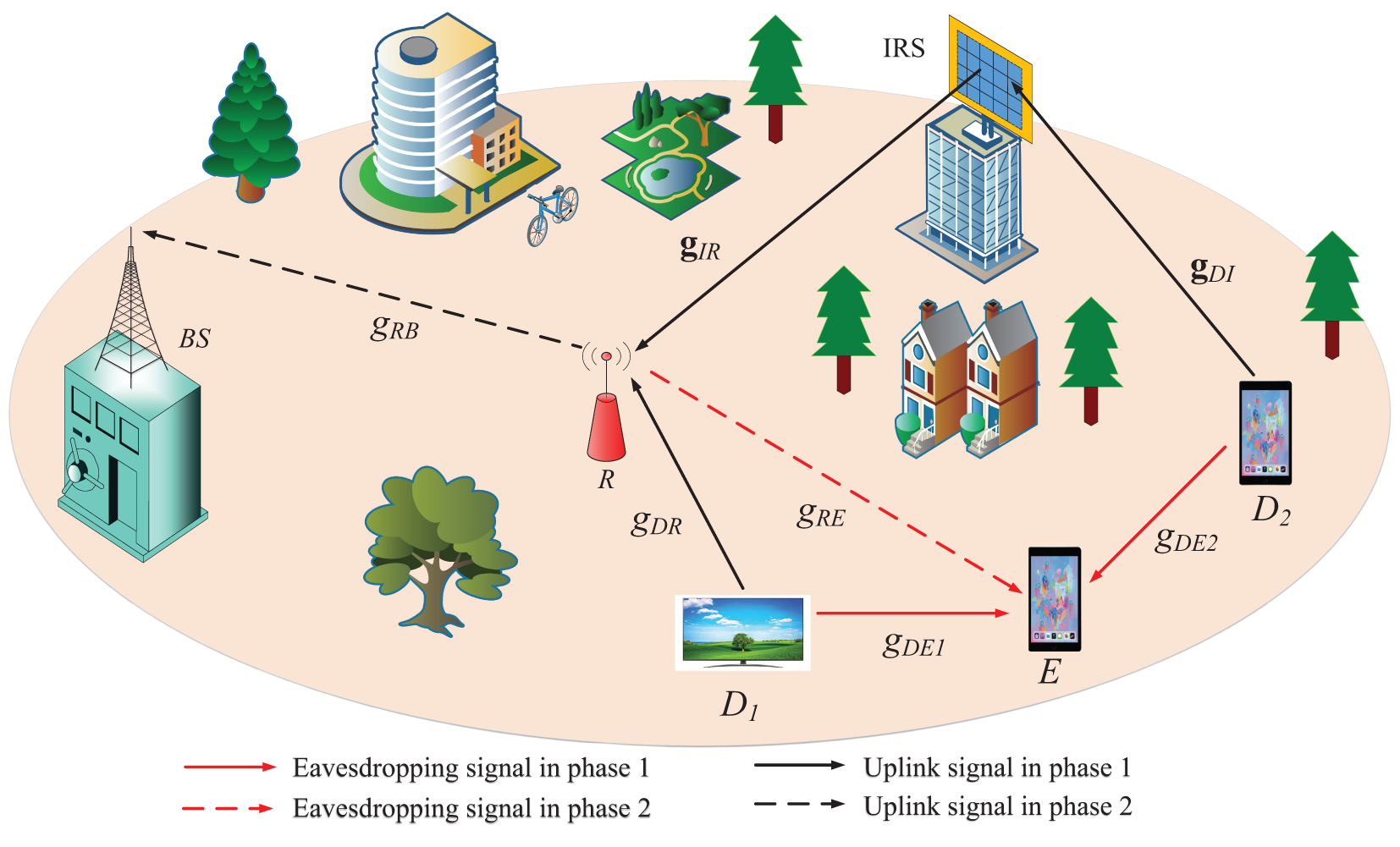
Figure 1: IRS-assisted secure network model for a NOMA relay system
The signal transmission process occurs in two phases:
i) First phase: The signal from user
ii) Second phase: R decodes the signals from both users and then transmits them to the BS. Meanwhile, E also eavesdrops on the signals from
It is important to note that the IRS only reflects signals during transmission and does not participate in signal decoding. At R, the successive interference cancellation (SIC) decoding process is performed to separate the signals from
To create the encoded packets, the user divides its original data into C packets and makes sure they are correctly encoded.
2.1 Evaluation of Signal in Phase 1
LetB denote the length of each FC packet. Assume that
where the link between
The signal for
where
We then use SIC to decode the
At the same time, the E also intercepts the signals from
where the between
Based on the operating principle of SIC, the E device will attempt to detect and decode the signal for
where
Following the detection of the
2.2 Evaluation of Signal in Phase 2
Following the successful decoding of the signals for
where the between R-BS link denoted by
As in (2), the
where
At the BS, use SIC to decode the
The eavesdropping device E concurrently intercepts the signal from R as it is sent to the BS. The following is the expression for the signal that was received at E from R [32,33]:
where the between R-E link denoted by
The E device will attempt to detect and decode the signal for
where
Next, we use SIC to find the
The OP in communication systems is the probability that an outage will occur when a user’s information rate drops below a certain goal rate. A commonly used statistic for assessing system performance in situations involving fixed-rate transmission is OP. In this part, we examine the uplink IRS-NOMA networks’ outage performance.
Since the SIC operation is assumed to be flawless in this study, the OP for
where
As stated in [4,30], the probability density function (PDF) and cumulative distribution function (CDF) for
Based on Eq. (13),
Using the CDF function of (15),
The OP of
Next, using [16, Eq. (21)], we may get the precise formula for
One FC packet’s OP for
Based on [3,30], our goal for the
are assumed without sacrificing generality.
According to [3,30], the PDF and CDF of
and
where
From (20),
Given (14) and (23),
It is rather challenging to derive the above equation in a closed form for the end outcome. As a result, we estimate the integral between 0 and a big number L [4,34].
Next, we let
Gaussian-Chebyshev quadrature is applied [35], and we obtain
where
Using (15) and (20),
By combining (28) and (29) into (20), the closed-form expression of
As with (18), the OP at
One crucial performance indicator for wireless communication systems is system throughput. System throughput research is very important for real-world applications. Information is sent continuously from the BS to
Moreover, by applying (32), the system throughput can be expressed as follows:
The slope of the OP curve in the high SNR range is the definition of diversity order in communication systems. It is frequently used to evaluate the outage performance of wireless communication networks and demonstrates how quickly the OP drops as the broadcast SNR increases. The following is a mathematical expression for the diversity order [4,5]:
where we assume that
4 IP-Based Security Evaluation
An important PLS metric is the IP, which measures the probability that a hacker may successfully collect and decode private data sent over a wireless channel. It is the likelihood that a security breach will occur if the E’s data rate is higher than the difference between the source transmission rate and the channel capacity of the authorized user.
Eqs. (6) and (12) may be used to determine user
Next, based on the CDF function mentioned in (15),
From (36), in the case of one FC packet, represent the IP of
Continuing, the IP of
Just as in (35), and based on (5) and (11), user
Using (39),
Next,
By combining (40) and (41) into (39), the closed-form expression of
As with (37), the IP at
5 DNN Approach for Predicting Main OP/IP
Here, we provide a DNN model for OP/IP evaluation2. In situations where the system model is complex and conventional mathematical derivation techniques are challenging to apply, this approach offers a data-driven solution. The DNN model will be utilized to reduce execution time and enhance accuracy.
5.1 The DNN Configuration Description
A feed-forward neural network is the type of DNN model that was employed in this investigation. Please see Fig. 2 for a thorough description of its setup. An input layer,
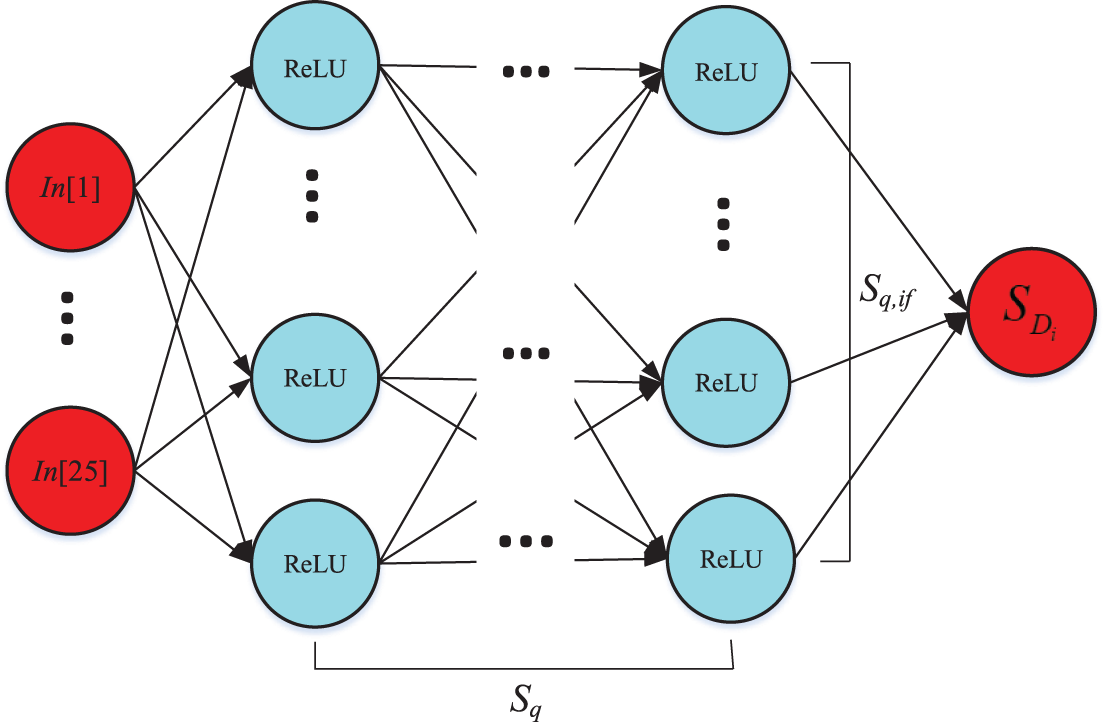
Figure 2: Building a DNN model for prediction
According to Table 1, the main system parameters are sent to the server as input values in this model. Each of these values corresponds to one of the 25 neurons. Predictions for OP or IP are produced by the output layer, which consists of a single neuron. According to sources [8,42,43], this procedure involves applying a linear function and the corresponding activation function. Furthermore, the parameters include solely weights and biases, and the neurons are 25 in number, matching the 25 input characteristics. The system uses the rectified linear unit (ReLU) activation function, and each hidden layer (designated as layer

The link between input and output is represented by parameter
The performance of the suggested DNN technique is assessed using the Mean Square Error, or MSE, which is specified by parameter
The performance of the network is assessed numerically in this section. Monte Carlo simulations are also used to confirm correctness. The main simulation parameters utilized in this work are selected based on recent studies in the field. Specifically, the power allocation coefficient is set to
By contrasting the training and validation curves, Fig. 3 verifies that the DNN attains the desired accuracy. Interestingly, the MSE successfully approaches its minimal level, as seen by the tight alignment of these two curves. It takes 12 epochs to attain the lowest MSE.
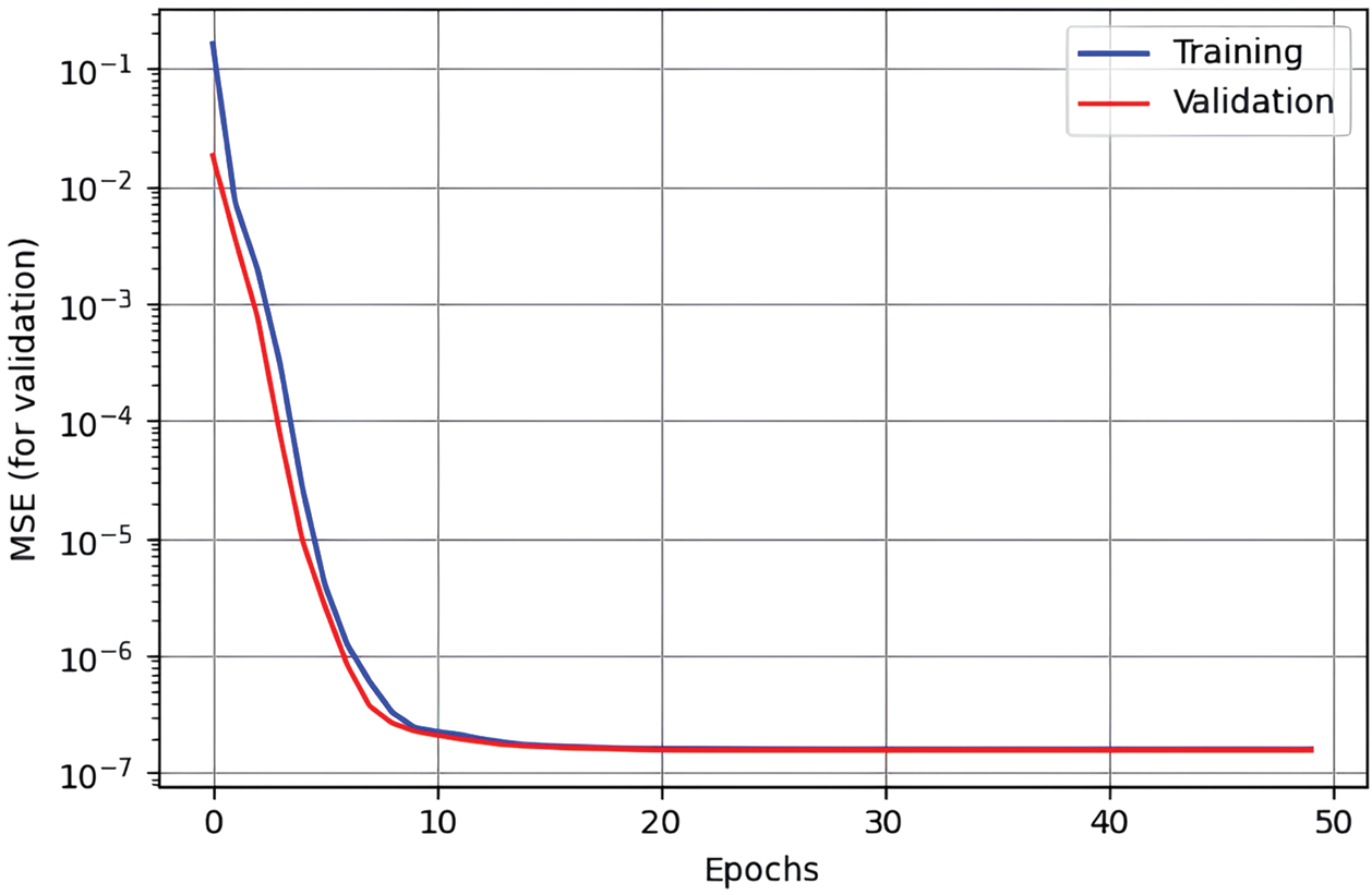
Figure 3: The convergence of the MSE for user
The OP of the uplink IRS-NOMA system for different values of
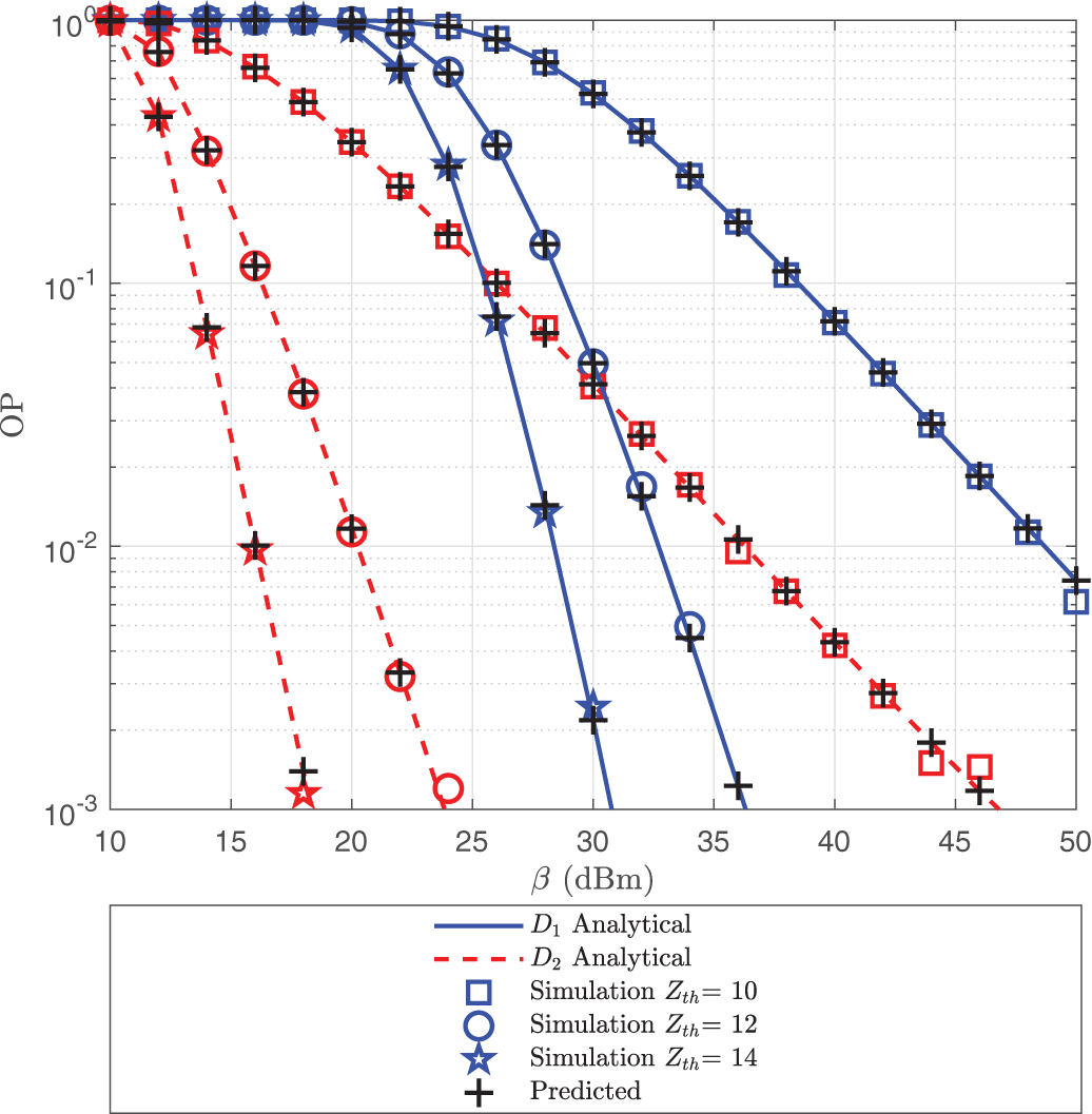
Figure 4: OP of
Fig. 5 displays the OP of the uplink IRS-NOMA system for a range of
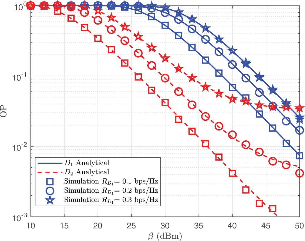
Figure 5: OP of
As the number of elements H varies, Fig. 6 shows the OP of both users as a function of
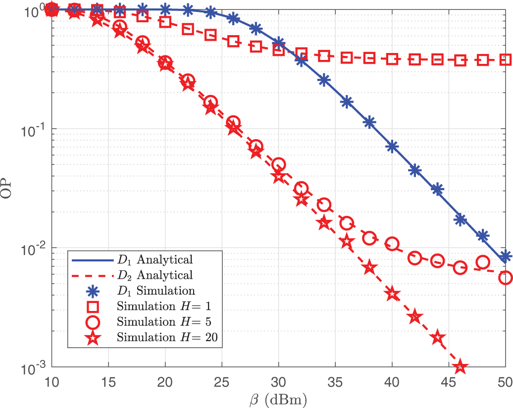
Figure 6: OP of
As we modify parameter A, we exhibit the IP for two users as a function of parameter
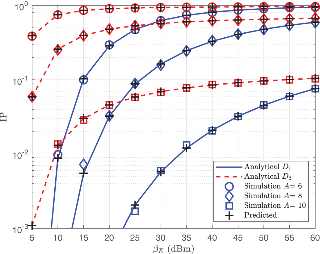
Figure 7: IP of
The IP is displayed vs. the threshold parameter
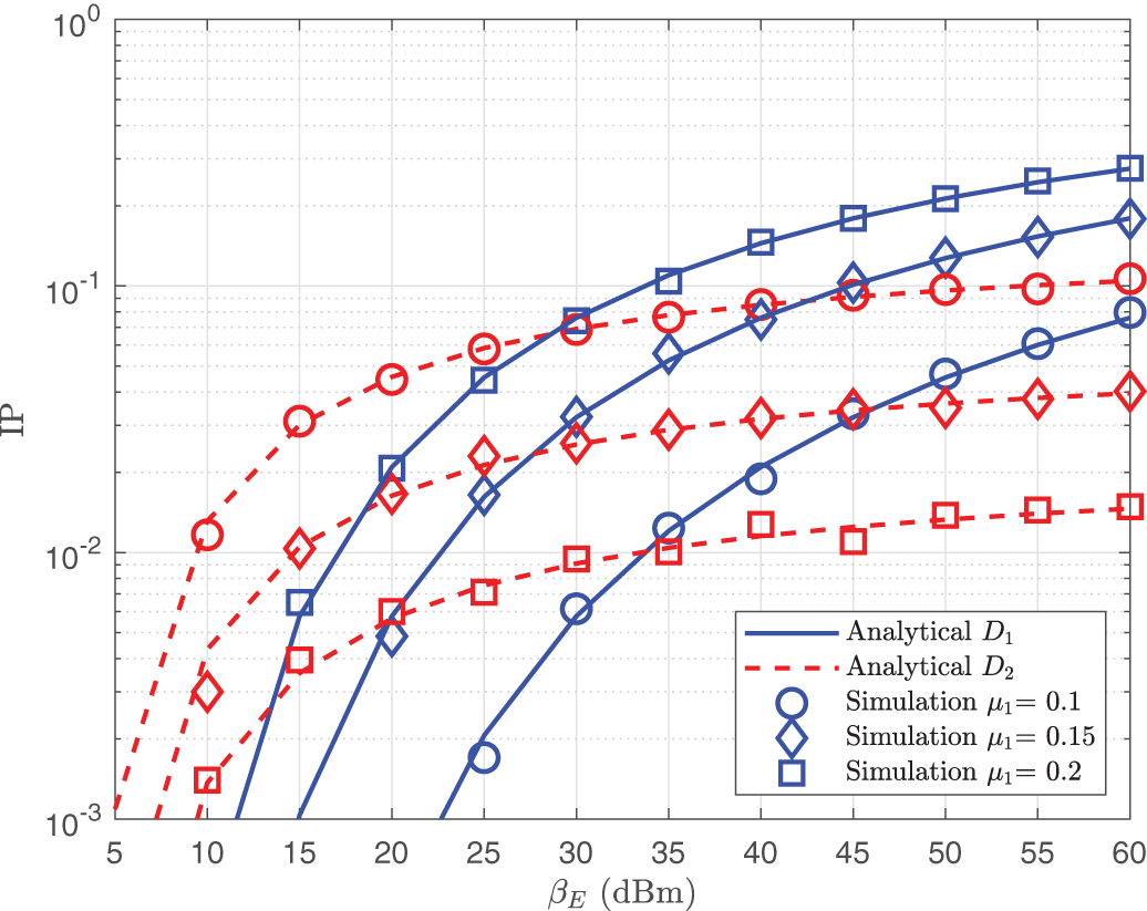
Figure 8: IP of
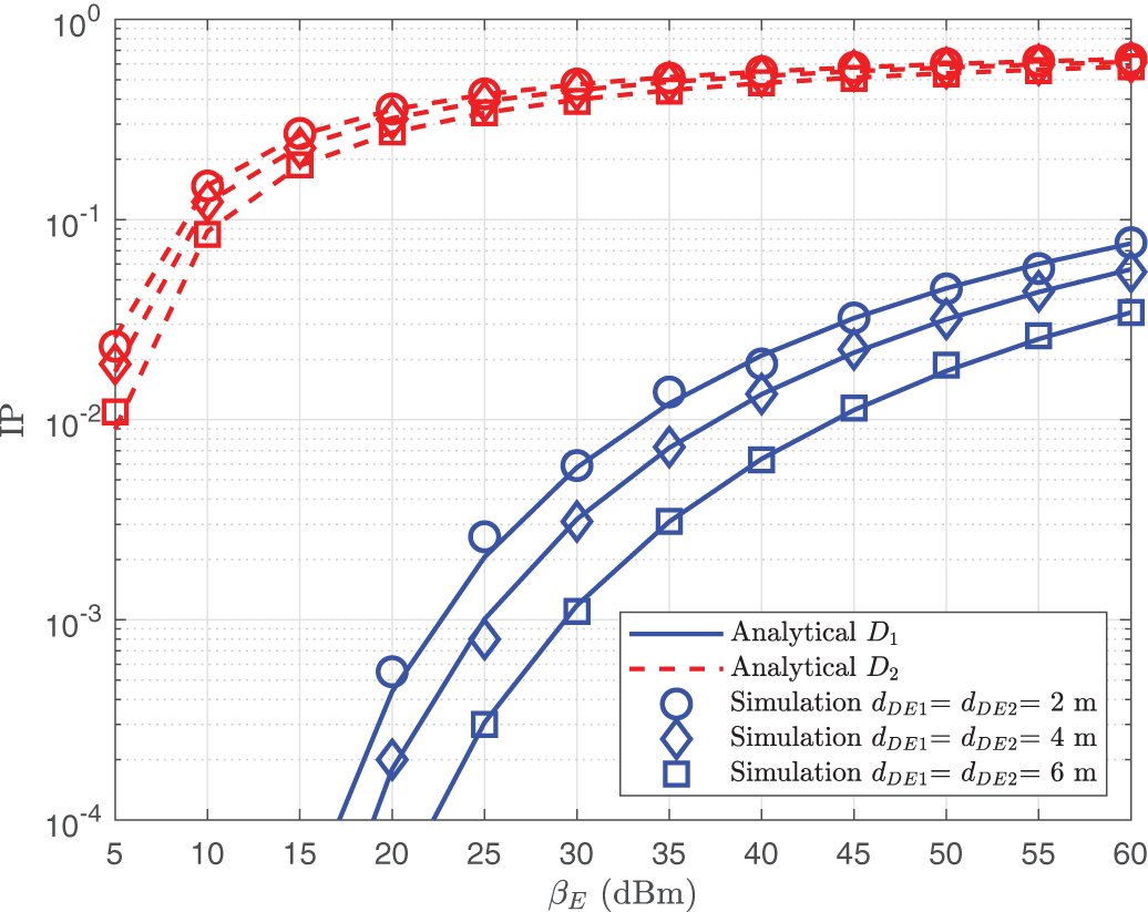
Figure 9: IP of
The throughput performance of user
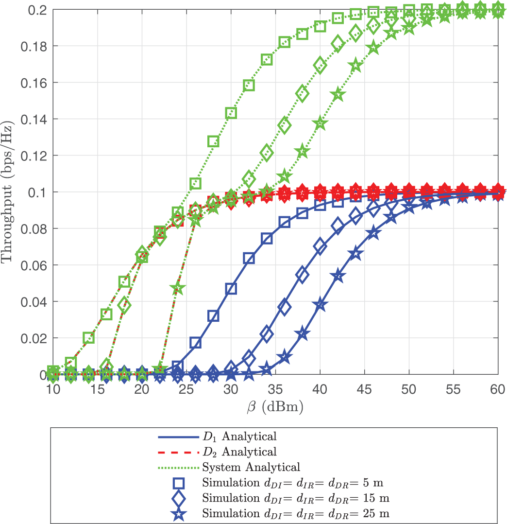
Figure 10: Throughput of
The obtained results clearly demonstrate that the system’s outage and intercept performance are susceptible to variations in key parameters such as H,
This study analyzes the OP and IP of an uplink NOMA system assisted by an IRS and utilizing FC, while also considering the presence of an eavesdropper. Additionally, a DNN is integrated into the system to predict its performance. The uplink NOMA transmission system demonstrates strong security performance due to the use of dual transmission links (including relay forwarding) from end users to the BS, combined with IRS assistance. Closed-form expressions for OP and IP are derived to evaluate the system’s reliability and security. Simulation results indicate that the system’s security performance is influenced by factors such as power allocation, the number of IRS reflecting elements, user threshold rates, encoded packet limitations, and power allocation coefficients. The theoretical findings in this study have broad applicability for deploying uplink NOMA in mobile networks. Simulations show strong agreement between theoretical and empirical results, with simulation points closely matching analytical predictions. This validates the accuracy of the proposed formulas and ensures the reliability of the data analysis in this study.
We are conscious of several limitations in our research. Despite the performance improvements enabled by the IRS, the system’s OP and IP remain sensitive to several practical factors, such as user distance, channel fading, and IRS configuration. These factors may limit the achievable gains in realistic scenarios, particularly when users are located far from the IRS or experience severe path loss. Therefore, further research is needed to develop adaptive IRS designs and robust optimization strategies to maintain system reliability under diverse deployment conditions. This highlights the need for future studies that explore more resilient IRS-assisted communication schemes and investigate their effectiveness under practical constraints. Additionally, the present system model has a fixed user count and a more straightforward network design. The scalability of the proposed method may be constrained in real-world scenarios where user density is increasing or network architecture is changing dynamically. Future studies should include more flexible and scalable designs to maintain performance in a range of complex network situations. The research can be extended by applying the model to systems with a larger number of users, allowing for security performance analysis in more complex environments. Potential scenarios include multi-user environments with resource competition or urban settings with numerous obstacles affecting signal transmission. Finally, to verify the accuracy and feasibility of the theoretical model and developed algorithms, conducting real-world experiments would be a crucial step in demonstrating the effectiveness of the proposed solutions.
Acknowledgement: The authors are grateful to all the editors and anonymous reviewers for their comments and suggestions.
Funding Statement: This work was supported in part by Vietnam National Foundation for Science and Technology Development (NAFOSTED) under Grant 102.04-2021.57; and in part by Culture, Sports and Tourism R&D Program through the Korea Creative Content Agency grant funded by the Ministry of Culture, Sports and Tourism in 2024 (Project Name: Global Talent Training Program for Copyright Management Technology in Game Contents, Project Number: RS-2024-00396709, Contribution Rate: 100%).
Author Contributions: Phu Tran Tin, Quy-Anh Bui, and Minh-Sang Van Nguyen designed the algorithm, performed the theoretical analysis, checked the results, and wrote the manuscript. Phu Tran Tin and Minh-Sang Van Nguyen implemented the simulation and contributed to the manuscript preparation. Agbotiname Lucky Imoize and Byung-Seo Kim were responsible for formulating the research issues and revising the paper. All authors reviewed the results and approved the final version of the manuscript.
Availability of Data and Materials: All data generated or analyzed during this study are included in this published article.
Ethics Approval: Not applicable.
Conflicts of Interest: The authors declare no conflicts of interest to report regarding the present study.
1To streamline the analysis and concentrate on phase shift optimization, the IRS’s placement and number of elements are set in this study. Future studies will examine the open research question of optimizing the IRS deployment position and number of elements to improve system performance and communication security
2Although the DNN model offers a quick and efficient method for predicting key performance metrics like OP and IP, it’s crucial to understand that the accuracy of these predictions is directly impacted by the model’s quality [8,40,41]. Since the model is data-driven by nature, factors that affect its output include the training dataset, the network architecture, and the optimization strategies used during training. Consequently, meticulous training procedures and thorough validation are required to ensure the accuracy of the forecasts. Instead of replacing traditional analytical equations, the DNN is employed in this study as an auxiliary approach to address scenarios when regular mathematical modeling is not viable due to the system’s complexity.
References
1. Hamza KM, Basharat S, Jung H, Gidlund M, Hassan SA. Secrecy analysis of RIS-assisted uplink NOMA systems under nakagami-m fading. In: 2024 IEEE International Conference on Communications Workshops (ICC Workshops). Denver, CO, USA; 2024. p. 1511–6. [Google Scholar]
2. Dai L, Wang B, Yuan Y, Han S, Chih-lin I, Wang Z. Non-orthogonal multiple access for 5G: solutions, challenges, opportunities, and future research trends. IEEE Commun Mag. 2015;53(9):74–81. doi:10.1109/mcom.2015.7263349. [Google Scholar] [CrossRef]
3. Tin PT, Nguyen MSV, Tran DH, Nguyen CT, Chatzinotas S, Ding Z, et al. Performance analysis of user pairing for active RIS-enabled cooperative NOMA in 6G cognitive radio networks. IEEE Internet Things J. 2024;11(23):37675–92. doi:10.1109/jiot.2024.3439377. [Google Scholar] [CrossRef]
4. Van Nguyen MS, Do DT, Vahid A, Muhaidat S, Sicker D. Enhancing NOMA backscatter IoT communications with RIS. IEEE Internet Things J. 2024;11(4):5604–22. doi:10.1109/jiot.2023.3308786. [Google Scholar] [CrossRef]
5. Gong X, Huang C, Yue X, Yang Z, Liu F. Performance analysis of RIS assisted NOMA networks over rician fading channels. Comput Model Eng Sci. 2023;135(3):2531–55. doi:10.32604/cmes.2023.024940. [Google Scholar] [CrossRef]
6. Le AT, Vu TH, Benevides da Costa D, Voznak M. Hybrid power-frequency multiple access with SIC-free for holographic reconfigurable intelligent surface-based systems. IEEE Wirel Commun Lett. 2025;14(5):1566–70. doi:10.1109/lwc.2025.3549228. [Google Scholar] [CrossRef]
7. Le AT, Vu TH, Nguyen TN, Minh BV, Voznak M. On performance of cooperative satellite-AAV-secured reconfigurable intelligent surface systems with phase errors. IEEE Commun Lett. 2025;29(4):799–803. doi:10.1109/lcomm.2025.3543732. [Google Scholar] [CrossRef]
8. Tran Tin P, van Nguyen MS, Trung Duy T, Vu Minh B, Kim BS, Rejfek L. Enhancing secrecy performance using fountain codes and NOMA under joint cooperative jamming technique and intelligent reflective surface. IEEE Access. 2024;12:117399–417. doi:10.1109/access.2024.3447531. [Google Scholar] [CrossRef]
9. Sang NQ, Kim HY, Nguyen TN, Vu MB, Tran PT, Duy TT, et al. Performance of RIS-secured short-packet NOMA systems with discrete phase-shifter to protect digital content and copyright against untrusted user. IEEE Access. 2025;13:21580–93. doi:10.1109/access.2025.3535813. [Google Scholar] [CrossRef]
10. Tang X, Liu R, Spasojevic P, Poor HV. Interference-assisted secret communication. In: 2008 IEEE Information Theory Workshop. Porto, Portugal; 2008. p. 164–8. doi:10.1109/itw.2008.4578643. [Google Scholar] [CrossRef]
11. Zhang R, Song L, Han Z, Jiao B, Debbah M. Physical layer security for two way relay communications with friendly jammers. In: 2010 IEEE Global Telecommunications Conference GLOBECOM 2010. Miami, FL, USA; 2010. p. 1–6. [Google Scholar]
12. Richter J, Scheunert C, Engelmann S, Jorswieck EA. Weak secrecy in the multiway untrusted relay channel with compute-and-forward. IEEE Trans Inf Forens Secur. 2015;10(6):1262–73. doi:10.1109/tifs.2015.2405903. [Google Scholar] [CrossRef]
13. Zhang W, Chen J, Kuo Y, Zhou Y. Artificial-noise-aided optimal beamforming in layered physical layer security. IEEE Commun Lett. 2019;23(1):72–5. doi:10.1109/lcomm.2018.2881182. [Google Scholar] [CrossRef]
14. Van Nguyen MS, Do DT, Tin PT, Vahid A. Secure performance analysis of user pairs in active reconfigurable intelligent surface-aided IoT systems. IEEE Syst J. 2025;19(2):370–81. doi:10.1109/jsyst.2025.3553818. [Google Scholar] [CrossRef]
15. Nguyen SQ, Tran PT, Minh BV, Duy TT, Le AT, Rejfek L, et al. Statistical analysis of the sum of double random variables for security applications in RIS-assisted NOMA networks with a direct link. Electronics. 2025;14(2):390. doi:10.3390/electronics14020392. [Google Scholar] [CrossRef]
16. Zheng Z, Yuan L, Fang F. Performance analysis of fountain coded non-orthogonal multiple access with finite blocklength. IEEE Wirel Commun Lett. 2021;10(8):1752–6. doi:10.1109/lwc.2021.3078811. [Google Scholar] [CrossRef]
17. Yuan L, Kim KJ, Zhang J. Cross-Layer design for fountain coded non-orthogonal multiple access transmission. In: ICC 2019—2019 IEEE International Conference on Communications (ICC). Shanghai, China; 2019. p. 1–5. [Google Scholar]
18. Douglass NP, Langel J, Moore WJ, Ng L, Dudukovich RM, Mal-Sarkar S. Application of fountain code to high-rate delay tolerant networks. IEEE Access. 2023;11:100845–55. doi:10.1109/access.2023.3315659. [Google Scholar] [CrossRef]
19. Yue J, Lin Z, Vucetic B. Distributed fountain codes with adaptive unequal error protection in wireless relay networks. IEEE Trans Wirel Commun. 2014;13(8):4220–31. doi:10.1109/twc.2014.2314632. [Google Scholar] [CrossRef]
20. Tu LT, Nguyen TN, Duy TT, Tran PT, Voznak M, Aravanis AI. Broadcasting in cognitive radio networks: a fountain codes approach. IEEE Trans Veh Technol. 2022;71(10):11289–94. doi:10.1109/tvt.2022.3188969. [Google Scholar] [CrossRef]
21. Ali A, Kwak KS, Tran NH, Han Z, Niyato D, Zeshan F, et al. RaptorQ-based efficient multimedia transmission over cooperative cellular cognitive radio networks. IEEE Trans Veh Technol. 2018;67(8):7275–89. doi:10.1109/tvt.2018.2832292. [Google Scholar] [CrossRef]
22. Nguyen TN, Minh BV, Tran DH, Le TL, Le AT, Nguyen QS, et al. Security-reliability analysis of AF full-duplex relay networks using self-energy recycling and deep neural networks. Sensors. 2023;23(17):7618. doi:10.3390/s23177618. [Google Scholar] [PubMed] [CrossRef]
23. Al-Garadi MA, Mohamed A, Al-Ali AK, Du X, Ali I, Guizani M. A survey of machine and deep learning methods for Internet of Things (IoT) security. IEEE Commun Surv Tutor. 2020;22(3):1646–85. [Google Scholar]
24. Hammouti HE, Ghogho M, Raza Zaidi SA. A machine learning approach to predicting coverage in random wireless networks. In: 2018 IEEE Globecom Workshops (GC Wkshps). Abu Dhabi, United Arab Emirates; 2018. p. 1–6. doi:10.1109/glocomw.2018.8644199. [Google Scholar] [CrossRef]
25. Bao T, Zhu J, Yang HC, Hasna MO. Secrecy outage performance of ground-to-air communications with multiple aerial eavesdroppers and its deep learning evaluation. IEEE Wirel Commun Lett. 2020;9(9):1351–5. doi:10.1109/lwc.2020.2990337. [Google Scholar] [CrossRef]
26. Tin PT, Van Nguyen MS, Duy TT, Pham VH, Kim BS. Combination of RIS and fountain codes in NOMA relay wireless networks for enhancing system performance and security. ICT Express. 2025;11(4):5604. doi:10.1016/j.icte.2025.05.012. [Google Scholar] [CrossRef]
27. Nguyen MSV, Do DT, Afghah F, Islam SMR, Le AT. Exploiting secrecy performance of uplink NOMA in cellular networks. IEEE Access. 2021;9:95135–54. doi:10.1109/access.2021.3092830. [Google Scholar] [CrossRef]
28. Lv L, Jiang H, Ding Z, Yang L, Chen J. Secrecy-enhancing design for cooperative downlink and uplink NOMA with an untrusted relay. IEEE Trans Commun. 2020;68(3):1698–715. doi:10.1109/tcomm.2019.2960345. [Google Scholar] [CrossRef]
29. Li W, Du Q, Sun L, Ren P, Wang Y. Security enhanced via dynamic fountain code design for wireless delivery. In: 2016 IEEE Wireless Communications and Networking Conference. Doha, Qatar; 2016. p. 1–6. [Google Scholar]
30. Cheng Y, Li KH, Liu Y, Teh KC, Vincent Poor H. Downlink and uplink intelligent reflecting surface aided networks: NOMA and OMA. IEEE Trans Wirel Commun. 2021;20(6):3988–4000. doi:10.1109/twc.2021.3054841. [Google Scholar] [CrossRef]
31. Kader MF, Shin SY. Coordinated direct and relay transmission using uplink NOMA. IEEE Wirel Commun Lett. 2018;7(3):400–3. doi:10.1109/lwc.2017.2779778. [Google Scholar] [CrossRef]
32. Chen J, Yang L, Alouini MS. Physical layer security for cooperative NOMA systems. IEEE Trans Veh Technol. 2018;67(5):4645–9. doi:10.1109/tvt.2017.2789223. [Google Scholar] [CrossRef]
33. Cao K, Ding H, Wang B, Lv L, Tian J, Wei Q, et al. Enhancing physical-layer security for IoT with nonorthogonal multiple access assisted semi-grant-free transmission. IEEE Internet Things J. 2022;9(24):24669–81. doi:10.1109/jiot.2022.3193189. [Google Scholar] [CrossRef]
34. Zhang Q, Zhang L, Liang YC, Kam PY. Backscatter-NOMA: a symbiotic system of cellular and Internet-of-Things networks. IEEE Access. 2019;7:20000–13. doi:10.1109/access.2019.2897822. [Google Scholar] [CrossRef]
35. Gradshteyn IS, Ryzhik IM. Table of integrals, series, and products. San Diego, CA, USA: Academic Press; 2014. [Google Scholar]
36. Do DT, Nguyen MSV, Jameel F, Jäntti R, Ansari IS. Performance evaluation of relay-aided CR-NOMA for beyond 5G communications. IEEE Access. 2020;8:134838–55. doi:10.1109/access.2020.3010842. [Google Scholar] [CrossRef]
37. Song Y, Yang W, Xiang Z, Wang B, Cai Y. Secure transmission in mmWave NOMA networks with cognitive power allocation. IEEE Access. 2019;7:76104–19. doi:10.1109/access.2019.2920963. [Google Scholar] [CrossRef]
38. Niu H, Iwai M, Sezaki K, Sun L, Du Q. Exploiting fountain codes for secure wireless delivery. IEEE Commun Lett. 2014;18(5):777–80. doi:10.1109/lcomm.2014.030914.140030. [Google Scholar] [CrossRef]
39. Wang X, Chen W, Cao Z. A rateless coding based multi-relay cooperative transmission scheme for cognitive radio networks. In: GLOBECOM 2009—2009 IEEE Global Telecommunications Conference. Honolulu, HI, USA; 2009. p. 1–6. [Google Scholar]
40. Yadav K, Upadhyay PK, Moualeu JM, Osman AAF, Nardelli PHJ. Deep learning-based secrecy performance of UAV-IRS NOMA systems with friendly jamming. IEEE Open J Commun Soc. 2025;6:4533–48. doi:10.1109/ojcoms.2025.3570923. [Google Scholar] [CrossRef]
41. Kamble A, Dalwadi H, Shukla MK, Pandey OJ, Singh VK. Medical sensor data security: a DNN framework for SOP prediction in two-way relay NOMA systems. IEEE Sens Lett. 2025;9(2):1–4. doi:10.1109/lsens.2025.3528978. [Google Scholar] [CrossRef]
42. Shim K, Do TN, Nguyen TV, DBd Costa, An B. Enhancing PHY-security of FD-enabled NOMA systems using jamming and user selection: performance analysis and DNN evaluation. IEEE Internet Things J. 2021;8(24):17476–94. doi:10.1109/jiot.2021.3080425. [Google Scholar] [CrossRef]
43. Do TN, Kaddoum G, Nguyen TL, da Costa DB, Haas ZJ. Aerial reconfigurable intelligent surface-aided wireless communication systems. In: 2021 IEEE 32nd Annual International Symposium on Personal, Indoor and Mobile Radio Communications (PIMRC). Helsinki, Finland; 2021. p. 525–30. [Google Scholar]
Cite This Article
 Copyright © 2025 The Author(s). Published by Tech Science Press.
This work is licensed under a Creative Commons Attribution 4.0 International License , which permits unrestricted use, distribution, and reproduction in any medium, provided the original work is properly cited.
 Downloads
 Citation Tools